EP4272599A1 - Detangling-straightening comb for hairdryer or blow-dryer brush - Google Patents
Detangling-straightening comb for hairdryer or blow-dryer brush Download PDFInfo
- Publication number
- EP4272599A1 EP4272599A1 EP22171086.6A EP22171086A EP4272599A1 EP 4272599 A1 EP4272599 A1 EP 4272599A1 EP 22171086 A EP22171086 A EP 22171086A EP 4272599 A1 EP4272599 A1 EP 4272599A1
- Authority
- EP
- European Patent Office
- Prior art keywords
- teeth
- comb
- comb according
- hair
- tooth
- Prior art date
- Legal status (The legal status is an assumption and is not a legal conclusion. Google has not performed a legal analysis and makes no representation as to the accuracy of the status listed.)
- Pending
Links
- 238000007664 blowing Methods 0.000 claims abstract description 14
- 238000001035 drying Methods 0.000 claims abstract description 5
- 238000007493 shaping process Methods 0.000 claims abstract description 3
- 239000006096 absorbing agent Substances 0.000 claims description 4
- 230000035939 shock Effects 0.000 claims description 4
- 230000004888 barrier function Effects 0.000 claims description 3
- 230000003745 detangling effect Effects 0.000 description 6
- 208000031968 Cadaver Diseases 0.000 description 3
- 230000035515 penetration Effects 0.000 description 3
- 230000007423 decrease Effects 0.000 description 2
- 238000010438 heat treatment Methods 0.000 description 2
- 230000000750 progressive effect Effects 0.000 description 2
- 230000003068 static effect Effects 0.000 description 2
- 230000006978 adaptation Effects 0.000 description 1
- 230000000712 assembly Effects 0.000 description 1
- 238000000429 assembly Methods 0.000 description 1
- 210000001520 comb Anatomy 0.000 description 1
- 230000000295 complement effect Effects 0.000 description 1
- 230000001010 compromised effect Effects 0.000 description 1
- 239000012141 concentrate Substances 0.000 description 1
- 238000010586 diagram Methods 0.000 description 1
- 238000010981 drying operation Methods 0.000 description 1
- 230000004907 flux Effects 0.000 description 1
- 238000009499 grossing Methods 0.000 description 1
- 239000000463 material Substances 0.000 description 1
- 239000012528 membrane Substances 0.000 description 1
- 238000009423 ventilation Methods 0.000 description 1
- 238000005406 washing Methods 0.000 description 1
Images


Classifications
-
- A—HUMAN NECESSITIES
- A45—HAND OR TRAVELLING ARTICLES
- A45D—HAIRDRESSING OR SHAVING EQUIPMENT; EQUIPMENT FOR COSMETICS OR COSMETIC TREATMENTS, e.g. FOR MANICURING OR PEDICURING
- A45D20/00—Hair drying devices; Accessories therefor
- A45D20/04—Hot-air producers
- A45D20/08—Hot-air producers heated electrically
- A45D20/10—Hand-held drying devices, e.g. air douches
- A45D20/12—Details thereof or accessories therefor, e.g. nozzles, stands
- A45D20/122—Diffusers, e.g. for variable air flow
-
- A—HUMAN NECESSITIES
- A45—HAND OR TRAVELLING ARTICLES
- A45D—HAIRDRESSING OR SHAVING EQUIPMENT; EQUIPMENT FOR COSMETICS OR COSMETIC TREATMENTS, e.g. FOR MANICURING OR PEDICURING
- A45D24/00—Hair combs for care of the hair; Accessories therefor
- A45D24/02—Single-piece combs
Definitions
- the present invention relates to a hair dryer or blower brush accessory, more particularly a “two in one” type detangling-straightening comb used for detangling and straightening curly hair. It is intended to be attached to the outlet of a device capable of blowing hot air such as a hair dryer or blowing brush.
- an alternative is the use of a flow of heated air emitted by a device blowing through a “two in one” comb capable of both detangling and straightening. hair during the drying operation.
- the means used makes it possible to guide and concentrate the outgoing air flow towards a specific area of the user's hair.
- Different combs are currently used to stretch hair and make it easier to arrange and detangle curly hair.
- a straightener accessory to gently detangle and straighten hair when drying.
- WO00/25623 discloses a hair dryer or styling brush accessory comprising means for pinching a strand of hair with complementary gripping surfaces for tightening and straightening the strands of hair.
- the document US6009883 A describes a hair straightening nozzle formed by two parallel rows of teeth, arranged on opposite sides of the nozzle, such that air from the hair dryer passes through the opening of the nozzle, between the two rows of teeth .
- This nozzle is equipped with a heating bar located between the two rows and parallel to the teeth. The hair strands are straightened as they pass between the teeth and over the heat bar.
- the patent WO 2020/025919 A1 describes a hair styling accessory in the form of a comb adaptable to a hair dryer comprising an air inlet for receiving an air flow and an elongated slot-shaped air outlet in which a series of triangular-shaped comb teeth is mounted on a flexible bar to allow elastic movement of these teeth when using the accessory.
- the present invention relates to a hair detangling-straightener comb intended to be attached to the blowing end of an apparatus for shaping and drying hair, said comb comprising a hollow body with an air inlet and a support comprising a plurality of teeth, the teeth comprising an enlarged base on the proximal side and a pointed apex on the distal side, the profile of said teeth of the base on the proximal side having a corrugated shape progressively truncated on its corrugated parts starting from the proximal side towards the distal side of the teeth.
- the present invention also discloses a hair dryer comprising a comb according to the invention with an electrical connection and a control panel allowing the movement of the mobile carriage(s) supporting the teeth.
- the present invention also discloses a blowing brush comprising a comb according to the invention
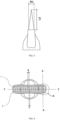
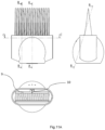
- FIG. 1 is a perspective view of the straightener comb adaptable to a hair dryer according to the invention.
- THE figures 2 , 3 and 4 respectively represent plan views, profile views and the opening of the straightener comb according to the invention.
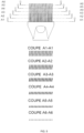
- FIG. 5 presents six progressive cuts A1-A1 up to A6-A6 through the teeth of the straightener accessory according to the invention, starting from the proximal base on the support side to the top on the distal side.
- These sections show the evolution of the profile and the deviation undergone by the strand of hair when passing between the teeth of the comb from the base to the top of the teeth.
- the teeth At the base, on the proximal side, the teeth have a width Bd and a wave-shaped profile which gradually attenuates towards the distal side of the teeth as the width of the teeth decreases towards the tip, the distal side.
- the shape of the wave on the proximal side of the tooth comprises a first part curved in a first direction 7 and a second part curved 8 in a second direction.
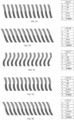
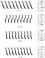
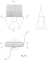
- THE figures 6 to 8 represent a series of non-exhaustive and non-limiting geometric configurations of the teeth with a wave-shaped configuration on the proximal side of the comb according to the invention.
- the possible amplitude of the undulation depends on both the space between the teeth, the thickness of the teeth and the angles of the tangents and inclination of the teeth.
- the figures below show the angles of the tangents ⁇ on the curvatures of the wave-shaped structure of the teeth on the proximal side of the comb as well as the average inclination ⁇ of the base of the tooth on the proximal side with respect to the perpendicular to the longitudinal axis of the comb.
- the angle ⁇ represents the average deviation that the lock of hair undergoes at the base of the teeth during its passage. The higher the angle ⁇ , the more restrictive the passage of the lock of hair through the teeth is and the more it is stretched, the force exerted for passage through the teeth being high.
- the evolving profile of the tooth allows the user to adjust the depth of penetration of the bit into the teeth in order to adapt the stretching force of the bit to an optimized straightening result.
- the teeth on the proximal side are curved in an opposite but symmetrical manner, the angles of the tangents ⁇ are therefore equal and, therefore, the direction of use of the passage of the strand has no influence on the penetration of the strand of hair , which allows any orientation for the hair dryer and the direction of straightening the strands.
- THE figures 6A-C represent preferred configurations with a tooth gap of 1.5 mm.
- the sign of the angles is only due to the orientation of the figure and the angles are to be taken in absolute value.
- With a space of only 1.5 mm between the teeth there is little freedom in terms of the amplitude of the undulation because it is necessary to ensure the free movement of the strand of hair even on the proximal side of the teeth.
- FIGS. 7A-E represent preferred configurations with a tooth gap of 2.5 mm. With a gap between the teeth increased to 2.5 mm, there is greater geometric freedom both in terms of inclination and in terms of amplitude of the undulation. This configuration is considered an optimum presenting a good balance between the number of teeth available in a defined space, freedom in the amplitude of the undulation and the inclination in relation to the direction of passage of the strand of hair.
- FIGS. 8A-D represent preferred configurations with a tooth gap of 4 mm. With such a gap between the teeth, we see even greater geometric freedom both in terms of inclination and in terms of amplitude of the undulation. Of course, increasing the gap between the teeth, as well as possibly increasing the thickness of the teeth, reduces the number of teeth and therefore the ability to comb. It is therefore a question of finding a balance between on the one hand an amplitude of undulation and an inclination of the teeth sufficient for smoothing and an appropriate spacing between the teeth allowing effective detangling, the wave form at the base of the tooth being the common denominator allowing tensioning of the hair strand during heat treatment and therefore appropriate straightening. Although curly hair is quite different in terms of texture densities and length from person to person, when tested on mannequins, the 7C, 7D and 8B configurations were found to be the most effective.
- THE figures 9 to 20 represent different examples of the detangling-straightening comb according to the invention, the teeth of which are mounted on a mobile carriage (9,11) allowing them to move in the three directions of space, generating a vibration/translation of the comb. Such vibration allows easier detangling compared to a static version of the comb according to the invention.
- the figures 9 to 11 illustrate an example of the detangling-straightener comb according to the invention in which the movement is carried out by an appropriate means such as for example a motor comprising a rod off-centered relative to the axis of rotation (10) placed in a central position on the longitudinal axis of the comb.
- an appropriate means such as for example a motor comprising a rod off-centered relative to the axis of rotation (10) placed in a central position on the longitudinal axis of the comb.
- Figure 9 represents a three-dimensional view of this example
- the Figure 10 represents an exploded view while the figures 11A And B represent a set of cuts through the accessory.
- THE figures 12 to 14 illustrate an example of the detangling-straightener comb according to the invention in which the movement is carried out using a single motor with an off-centered axis 10 placed in a lateral position.
- Figure 12 represents a three-dimensional view of this example
- Figure 13 represents an exploded view
- the figures 14A and B represent a set of cuts through the accessory.
- FIG. 15 to 17 illustrate an example of the detangling-straightening comb according to the invention in which the movement is carried out thanks to a vibrator comprising an unbalanced motor 12, such as for example a motor of the "precision microdrive Pico Vibe 306-103.006" type, placed in central position relative to the longitudinal axis of the comb.
- a vibrator comprising an unbalanced motor 12, such as for example a motor of the "precision microdrive Pico Vibe 306-103.006" type, placed in central position relative to the longitudinal axis of the comb.
- FIG 15 represents a three-dimensional view of this example
- the Figure 16 represents an exploded view while the figures 17A And B represent a set of cuts through the accessory.
- the section also shows the presence of an elastic shock absorber 19 intended to absorb any contact between the support envelope 3 and the mobile carriage.
- THE figures 18 to 20 illustrate an example of the detangling-straightener comb according to the invention in which the movement is carried out thanks to two motors 10 comprising rods offset relative to the axis of the motor placed at both ends on the longitudinal axis of the comb, allowing each to control a two-part carriage 11 independently, each carriage comprising a set of teeth.
- Figure 18 represents a three-dimensional view of this example
- the Figure 19 represents an exploded view
- the figures 20A And B represent a set of cuts through the accessory.
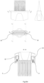
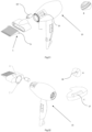
- THE figures 21 to 25 represent an example of the detangling-straightener comb according to the invention, mounted on the air outlet of a conventional hair dryer.
- the detangler-straightener comb in these figures comprises a mobile carriage which is set in motion by an off-center rod motor 10 placed eccentrically relative to the air outlet axis of the hair dryer and the inlet of the hair dryer. air in the accessory.
- the figures 21 and 22 represent an exploded view in three dimensions
- the Figure 23 represents a front view
- the figure 24 And 25 represent a set of cuts through the comb mounted on the hairdryer.
- Detail B of the Figure 21 shows the low voltage electrical connections that power the motor while allowing the accessory to remain rotating on the hair dryer.
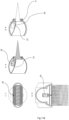
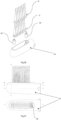
- THE figures 26 to 28 represent an example of the detangling-straightener comb according to the invention, adapted as an accessory to a blowing brush.
- Figure 26 represents an exploded three-dimensional view of the Figure 27 representing a profile view and a top view
- Figure 28 represents a set of cuts through the blower brush.
- the detangling-straightening comb of the present invention is adaptable to the outlet of a hair dryer or a blowing brush. It comprises a series of teeth of essentially triangular shape whose profile evolves in a particular and progressive manner from the proximal base towards the tip.
- the profile of the teeth presents an approximately sinusoidal type waveform with a variable amplitude on the proximal side on the support, and an angle ⁇ of inclination relative to the direction of passage of the strand and therefore of deviation of the strands of hair to comb and detangle.
- the profile gradually attenuates towards the distal side of the teeth of the comb by truncating the corrugated parts 7 and 8, which allows the strands of hair to be tightened as the strand penetrates deeper and deeper into the comb towards the base of the teeth, proximal side, and place them under tension against the hot air coming from the hair dryer and passing between the rows of teeth.
- the wavy shape of the teeth on the proximal side also increases the contact surface between the tooth and the strand of hair and therefore the effectiveness of the treatment.
- FIG. 5 shows the change in the section of the tooth profile from the proximal to the distal side of the teeth, which allows the user to adjust the traction force on the strand of hair by adjusting the penetration depth of the wick.
- THE figures 1 and 2 respectively present a front perspective view and a plan view of the straightener comb 1 according to the invention.
- the comb 1 includes an air inlet 2 intended to receive the air flow coming from an air outlet end of a hair dryer or a blowing brush.
- the air inlet 2 of the straightener comb is an opening whose shape is adapted to the outlet mouth of the hair dryer or a blowing brush.
- the straightener comb according to the invention comprises a support 3 carrying a plurality of teeth 4 distributed regularly over the length of the support.
- Air inlet 2 has a generally circular section, which is suitable for engagement at the air outlet ends of most hair dryers.
- An intermediate piece can nevertheless be used as an adapter for hair dryers comprising an air outlet mouth unsuitable for the support of the straightener comb according to the invention.
- the adaptation is specific.
- the air flow emitted by the hair dryer enters through the air inlet 2 and passes through the plurality of teeth 4, guided by the support 3.
- the hot air flow is in direct contact with the hair strands. Hair held tight and taut by the wave-shaped profile of the teeth proximal to the base of the comb. As the comb is exposed to the flow of air coming out of a hairdryer, or a blowing brush, it can exceed 100°C, it must therefore be made with a material resistant to the maximum temperature that can be reached .
- FIG. 3 illustrates the side view of the comb 1 showing the total height, Ld, of each tooth 6 which is preferably between 25 mm and 85 mm, and preferably between 50 mm and 60 mm.
- the width of the base of each tooth 6, Bd is advantageously between 10 mm and 30 mm, and preferably between 15 mm and 20 mm. This is the apparent width including the waveform.
- the side view of comb 1 shows the side shape of tooth 6 which is generally triangular with possibly a rectangular base.
- the tip of the tooth contrary to the graphic representation, is never sharp but always has a radius of a few tenths of a millimeter.
- FIG. 4 illustrates the plan view of comb 1 which shows the alignment of the teeth.
- the wave profile at the base of the teeth comprises a first portion curved 7 located above the Y axis and a second curved portion 8 located below the Y axis. These two curves respectively have two tangents ⁇ whose inclination is equal.
- each tooth has a thickness ⁇ approximately equal to 2 mm and the teeth are spaced at a distance E of approximately 3 mm.
- the comb 1 comprises a plurality of teeth 4 connected to the proximal base on the support side 3.
- the plurality of teeth 4 can be molded and/or injected with the support 3 and the air inlet 2 in a single piece.
- assemblies of separately molded/injected parts can also be used, in particular for versions of the comb mounted on a mobile cart.
- FIG. 5 illustrates the front view of comb 1 with six cross sections through the length of teeth 4 from the proximal base on the support side 3 to the top 5 on the distal side.
- Each tooth has a wave-shaped profile or undulation, extending over the width of the support 3.
- the inclination of the tangent ⁇ of the curved part is compromised between 20° and 30°, preferably between 24 and 26°.
- the width of the teeth 4 gradually decreases from the base towards the end until reaching a parallelepiped cross section illustrated on sections A1-A1, A2-A2, A3-A3, A4-A4, A5-A5, and A6-A6 respectively.
- the detangling-straightener comb of the present invention can also be adapted to a blowing brush as shown in the figures 27 And 28 .
- the teeth of the detangling-straightener comb can be mounted on a mobile carriage allowing movement in the three directions of space, generating a vibration of the comb of a maximum amplitude of the order of a millimeter for an unbalanced motor 12.
- the amplitude of movement can be a few millimeters.
- the comb according to the invention can also comprise two independent carriages 11 driven by a motor 10 with an eccentric rod on each side of the accessory.
- Each of the carriages has one tooth out of two, which allows the comb to move in partial or complete phase opposition. This is how teeth 1,3,5,7,9, etc. are fixed on a first carriage and the teeth 2,4,6,8, etc. on a second carriage, the two carriages being able to be set in motion at different amplitudes and frequencies.
- thermal protection barrier 22 separating the motor compartment from the flow of hot air coming from the hair dryer or blower brush in order to protect the motors from the high temperatures which can be reached by the motor. air entering the accessory.
Abstract
Peigne démêleur-lisseur de cheveux destiné à être fixé à l'extrémité soufflante d'un appareil pour la mise en forme et le séchage des cheveux, ledit peigne comprenant un corps creux avec une entrée d'air et un support comportant une pluralité de dents, les dents comportant une base élargie du côté proximal et un sommet en pointe du côté distal, le profil desdites dents côté proximal présentant une forme ondulée progressivement tronquée sur ses parties ondulées en partant du côté proximal vers le côté distal des dents .Hair detangler-straightener comb intended to be attached to the blowing end of an apparatus for shaping and drying hair, said comb comprising a hollow body with an air inlet and a support comprising a plurality of teeth , the teeth comprising an enlarged base on the proximal side and a pointed apex on the distal side, the profile of said teeth on the proximal side having a corrugated shape progressively truncated on its corrugated parts starting from the proximal side towards the distal side of the teeth.
Description
La présente invention est relative à un accessoire de sèche-cheveux ou de brosse soufflante, plus particulièrement un peigne démêleur-lisseur de type « deux en un » utilisé pour démêler et lisser les cheveux frisés. Il est destiné à être fixé à la sortie d'un dispositif capable de souffler de l'air chaud comme un sèche-cheveux ou une brosse soufflante.The present invention relates to a hair dryer or blower brush accessory, more particularly a “two in one” type detangling-straightening comb used for detangling and straightening curly hair. It is intended to be attached to the outlet of a device capable of blowing hot air such as a hair dryer or blowing brush.
Les dispositifs de lissage des cheveux frisés sont bien connus de l'état de la technique et largement utilisés, plus particulièrement par les populations d'origine africaine ou afro-américaine. Le lissage mécanique des cheveux frisés ou fortement bouclés est généralement précédé par un démêlage/séchage après lavage des cheveux. Cette double opération se fait souvent avec un peigne dont les dents sont relativement espacées permettant le démêlage avant de s'attaquer au lissage avec un autre dispositif. Le lissage est généralement réalisé grâce à une source de chaleur utilisée simultanément avec une pression ou une tension exercée sur les mèches de cheveux. Néanmoins, ces manipulations successives prennent du temps et le lissage expose les cheveux à des contraintes thermiques et mécaniques importantes, ce qui peut les endommager dans la durée.Devices for straightening curly hair are well known to the state of the art and widely used, more particularly by populations of African or African-American origin. Mechanical straightening of frizzy or strongly curly hair is generally preceded by detangling/drying after washing the hair. This double operation is often done with a comb whose teeth are relatively spaced apart allowing detangling before tackling straightening with another device. Straightening is generally achieved using a heat source used simultaneously with pressure or tension exerted on the hair strands. However, these successive manipulations take time and straightening exposes the hair to significant thermal and mechanical stress, which can damage it over time.
Pour réduire ces contraintes appliquées sur les cheveux et gagner du temps, une alternative est l'utilisation d'un flux d'air chauffé émis par un dispositif soufflant à travers un peigne « deux en un » capable à la fois de démêler et de lisser les cheveux pendant l'opération de séchage. Le moyen utilisé permet de guider et de concentrer le flux d'air sortant vers une zone spécifique des cheveux de l'utilisateur. Différents peignes sont actuellement utilisés pour étirer les cheveux et faciliter l'arrangement et le démêlage des cheveux frisés. Il existe cependant toujours une demande croissante pour un accessoire lisseur permettant de démêler et de lisser les cheveux en douceur lors du séchage.To reduce these stresses applied to the hair and save time, an alternative is the use of a flow of heated air emitted by a device blowing through a “two in one” comb capable of both detangling and straightening. hair during the drying operation. The means used makes it possible to guide and concentrate the outgoing air flow towards a specific area of the user's hair. Different combs are currently used to stretch hair and make it easier to arrange and detangle curly hair. However, there is still a growing demand for a straightener accessory to gently detangle and straighten hair when drying.
Le document
Le document
Le document
Le brevet
La présente invention concerne un peigne démêleur-lisseur de cheveux destiné à être fixé à l'extrémité soufflante d'un appareil pour la mise en forme et le séchage des cheveux, ledit peigne comprenant un corps creux avec une entrée d'air et un support comportant une pluralité de dents, les dents comportant une base élargie du côté proximal et un sommet en pointe du côté distal, le profil desdites dents de la base côté proximal présentant une forme ondulée progressivement tronquée sur ses parties ondulées en partant du côté proximal vers le côté distal des dents.The present invention relates to a hair detangling-straightener comb intended to be attached to the blowing end of an apparatus for shaping and drying hair, said comb comprising a hollow body with an air inlet and a support comprising a plurality of teeth, the teeth comprising an enlarged base on the proximal side and a pointed apex on the distal side, the profile of said teeth of the base on the proximal side having a corrugated shape progressively truncated on its corrugated parts starting from the proximal side towards the distal side of the teeth.
Les modes préférés de la présente invention comportent une ou plusieurs des caractéristiques suivantes :
- l'inclinaison moyenne des dents par rapport à l'axe X présente un angle a, en valeur absolue, compris entre 5° et 25°, de préférence entre 10° et 20° à la base, du côté proximal des dents;
- la tangente des extrémités supérieure et inférieure de chaque dent du côté proximal présentent un angle β entre 20° et 50°, de préférence entre 30° et 40° par rapport à l'axe X ;
- le rapport entre la hauteur Ld et la largeur Bd de chaque dent et compris entre 2 et 8,5, de préférence entre 3 et 6 et de manière particulièrement préférée entre 3,5 et 5;
- chaque dent présente une épaisseur (ε) comprise entre 1,2 mm et 3 mm ;
- l'espace entre les dents E est compris entre 1 mm et 5 mm, de préférence entre 1,5 et 4 mm et de manière particulièrement préférée entre 1,8 et 3 mm ;
- le support comporte au moins un chariot mobile avec les dents désolidarisé du corps creux et au moins un moyen permettant la mise en mouvement du chariot mobile avec les dents dans au moins deux directions ;
- le au moins un moyen permettant la mise en mouvement du chariot mobile est un moteur comportant une tige excentrée par rapport à l'axe du moteur ou un vibreur comportant un moteur à balourd ;
- le vibreur est positionné de manière centrale ;
- le moteur comportant une tige excentrée par rapport à l'axe du moteur est positionné à une extrémité ou aux deux extrémités du chariot mobile ;
- le support comporte deux chariots mobiles, un premier chariot mobile supportant une rangée de dents paire et un second chariot mobile supportant une rangée de dents impaire et permettant la mise en mouvement des dents à rangées impaires et paires les unes par rapport aux autres par l'intermédiaire de deux moteurs M1 et M2 avec tige décentrée reliés respectivement au premier et au second chariot mobile ;
- le support comportant les chariots mobiles comporte un amortisseur élastique ;
- le corps creux comporte une barrière de protection thermique pour isoler le ou les moteurs dans le corps creux du flux d'air chaud.
- the average inclination of the teeth relative to the axis
- the tangent of the upper and lower ends of each tooth on the proximal side have an angle β between 20° and 50°, preferably between 30° and 40° relative to the X axis;
- the ratio between the height Ld and the width Bd of each tooth is between 2 and 8.5, preferably between 3 and 6 and particularly preferably between 3.5 and 5;
- each tooth has a thickness (ε) of between 1.2 mm and 3 mm;
- the space between the teeth E is between 1 mm and 5 mm, preferably between 1.5 and 4 mm and particularly preferably between 1.8 and 3 mm;
- the support comprises at least one movable carriage with the teeth separated from the hollow body and at least one means allowing the movement of the movable carriage with the teeth in at least two directions;
- the at least one means enabling the moving carriage to be set in motion is a motor comprising a rod eccentric with respect to the axis of the motor or a vibrator comprising an unbalanced motor;
- the vibrator is positioned centrally;
- the motor comprising a rod eccentric with respect to the axis of the motor is positioned at one end or at both ends of the mobile carriage;
- the support comprises two movable carriages, a first movable carriage supporting a row of even teeth and a second movable carriage supporting an odd row of teeth and allowing the teeth with odd and even rows to move relative to each other by the intermediate of two motors M1 and M2 with off-center rod connected respectively to the first and the second mobile carriage;
- the support comprising the mobile carriages comprises an elastic shock absorber;
- the hollow body includes a thermal protection barrier to isolate the motor(s) in the hollow body from the flow of hot air.
La présente invention divulgue également un sèche-cheveux comportant un peigne selon l'invention avec une connexion électrique et un tableau de commande permettant la mise en mouvement du ou des chariots mobiles supportant les dents.The present invention also discloses a hair dryer comprising a comb according to the invention with an electrical connection and a control panel allowing the movement of the mobile carriage(s) supporting the teeth.
La présente invention divulgue également une brosse soufflante comportant un peigne selon l'inventionThe present invention also discloses a blowing brush comprising a comb according to the invention
La
Les
La
Les
Données en exemple, deux variables principales de la structure des dents coté proximal représentées ci-dessous donnant lieu à 2 variantes principales, Twist 1 et Twist 2, la variante où les parties extérieures de la base de la dent sont perpendiculaires à l'axe longitudinal du peigne (Twist 2 avec α=vertical=0°) et la variante où la partie centrale de la base de la dent est perpendiculaire à l'axe longitudinal du peigne avec (Twist 1 avec γ=vertical=0°)Example data, two main variables of the structure of the teeth on the proximal side shown below giving rise to 2 main variants, Twist 1 and Twist 2, the variant where the outer parts of the tooth base are perpendicular to the longitudinal axis of the comb (Twist 2 with α=vertical=0°) and the variant where the central part of the base of the tooth is perpendicular to the longitudinal axis of the comb with (Twist 1 with γ=vertical=0°)
Les figures ci-dessous montrent les angles des tangentes β sur les courbures de la structure en forme d'onde des dents du côté proximal du peigne ainsi que l'inclinaison moyenne α de la base de la dent côté proximal par rapport à la perpendiculaire à l'axe longitudinal du peigne. L'angle α représente la déviation moyenne que subit la mèche de cheveux à la base des dents lors de son passage. Plus l'angle α est élevé, plus le passage de la mèche de cheveux à travers les dents est contraignant et plus celle-ci est étirée, la force exercée pour le passage à travers les dents étant élevée. Le profil évolutif de la dent, de la base côté proximal vers la pointe des dents, permet à l'utilisateur de régler la profondeur de pénétration de la mèche dans les dents afin d'adapter la force d'étirement de la mèche à un résultat de lissage optimisé. Les dents côté proximal sont courbées de manière opposée mais symétrique, les angles des tangentes β sont donc égales et, par conséquent, le sens d'utilisation du passage de la mèche n'a pas d'influence sur la pénétration de la mèche de cheveux, ce qui permet n'importe quelle orientation pour le sèche-cheveux et la direction de lissage des mèches.

Les
Les
Les
Les
En particulier, les
Les
Les
Les
Les
En particulier, les
Les
En particulier, la
- 1.1.
- Peigne démêleur-lisseurDetangler-straightener comb
- 2.2.
- Entrée d'airAir inlet
- 3.3.
- SupportSupport
- 4.4.
- Rangée de dentsRow of teeth
- 5.5.
- Partie distale de la dentDistal part of the tooth
- 6.6.
- Partie proximale de la dentProximal part of the tooth
- 7.7.
- Profil de la dent en forme d'onde côté proximal avec une première partie courbée dans un premier sensWave-shaped tooth profile on the proximal side with a first part curved in a first direction
- 8.8.
- Profil de la dent en forme d'onde côté proximal avec une seconde partie courbée dans un second sensWave-shaped tooth profile on the proximal side with a second part curved in a second direction
- 9.9.
- Support /chariot mobileMobile support/cart
- 10.10.
- Moteur comportant une tige décentrée par rapport à l'axe du moteurMotor comprising a rod offset relative to the axis of the motor
- 11.11.
- Support/chariot en deux parties portant respectivement une dent sur deux.Support/carriage in two parts carrying one tooth out of two respectively.
- 12.12.
- Vibreur (moteur à balourd)Vibrator (unbalanced motor)
- 13.13.
- Sèche-cheveuxhair dryer
- 14.14.
- Embout pour brosse soufflanteBlower brush attachment
- 15.15.
- Display de commande de mise en mouvement du peigneComb movement control display
- 16.16.
- Connexion électriqueElectrical connection
- 17.17.
- Connexion mécaniqueMechanical connection
- 18.18.
- Alimentations électriques du moteur et du display.Motor and display power supplies.
- 19.19.
- Amortisseur élastiqueElastic shock absorber
- 20.20.
- Membrane souple permettant au chariot mobile de se mouvoir, sans propagation de la vibration dans l'accessoire ni le sèche-cheveux.Flexible membrane allowing the mobile carriage to move, without propagation of vibration in the accessory or the hair dryer.
- 21.21.
- Ouvertures d'aération pour moteurEngine ventilation openings
- 22.22.
- Paroi de protection thermiqueThermal protection wall
Le peigne démêleur-lisseur de la présente invention est adaptable à la bouche de sortie d'un sèche-cheveux ou d'une brosse soufflante. Il comporte une série de dents de forme essentiellement triangulaire dont le profil évolue de manière particulière et progressive de la base proximale vers la pointe. Le profil des dents présente une forme d'onde de type approximativement sinusoïdale avec une amplitude variable du côté proximal sur le support, et un angle α d'inclinaison par rapport à la direction de passage de la mèche et donc de déviation des mèches de cheveux à peigner et à démêler. Le profil s'atténue progressivement vers le côté distal des dents du peigne en tronquant les parties ondulées 7 et 8, ce qui permet de serrer les mèches de cheveux au fur et à mesure que la mèche pénètre de plus en plus profondément dans le peigne vers la base des dents, côté proximal, et de les mettre sous tension face à l'air chaud provenant du sèche-cheveux et passant entre les rangées de dents. La forme ondulée des dents côté proximal agrandit également la surface de contact entre la dent et la mèche de cheveux et donc l'efficacité du traitement.
La
There
Les
L'entrée d'air 2 a une section généralement circulaire, qui est adaptée pour être engagée aux extrémités de sortie d'air de la plupart des sèche-cheveux. Une pièce intermédiaire peut néanmoins être utilisée comme adaptateur pour les sèche-cheveux comportant une bouche de sortie d'air inadaptée au support du peigne lisseur selon l'invention. Pour les brosses soufflantes, l'adaptation est spécifique.
Le flux d'air émis par le sèche-cheveux entre par l'entrée d'air 2 et passe à travers la pluralité de dents 4, guidé par le support 3. Le flux d'air chaud est en contact direct avec les mèches de cheveux serrées et tendues par le profil en forme d'onde des dents côté proximal à la base du peigne. Comme le peigne est exposé au flux d'air sortant d'un sèche-cheveux, ou d'une brosse soufflante, celui-ci peut dépasser 100 °C, il doit donc être fabriqué avec une matière résistante à la température maximale pouvant être atteinte.The air flow emitted by the hair dryer enters through the
La
En référence à la
La
Le peigne 1 comprend une pluralité de dents 4 reliées à la base proximale côté support 3. Dans les schémas illustrés sur les
La
Le peigne démêleur-lisseur de la présente invention peut également être adapté à une brosse soufflante comme le montrent les
Selon un mode préféré de l'invention, les dents du peigne démêleur-lisseur peuvent être montées sur un chariot mobile permettant la mise en mouvement dans les trois directions de l'espace, générant une vibration du peigne d'une amplitude maximale de l'ordre du millimètre pour un moteur à balourd 12. Pour les mouvements engendrés par les moteurs à tige décentrée par rapport à l'axe de moteur 10, l'amplitude de mouvement peut être de quelques millimètres.According to a preferred mode of the invention, the teeth of the detangling-straightener comb can be mounted on a mobile carriage allowing movement in the three directions of space, generating a vibration of the comb of a maximum amplitude of the order of a millimeter for an
Afin de mettre le peigne en mouvement, plusieurs moyens peuvent être envisagés comme l'utilisation d'un vibreur 12 par un moteur à balourd ou d'un ou de plusieurs moteurs 10 à tige excentrée dans l'accessoire. Les
Le peigne selon l'invention peut également comporter deux chariots indépendants 11 mus par un moteur 10 avec une tige excentrée de chaque côté de l'accessoire. Chacun des chariots comporte une dent sur deux, ce qui permet de mettre le peigne en mouvement en opposition de phase partielle ou complète. C'est ainsi que les dents 1,3,5,7,9, etc. sont fixées sur un premier chariot et les dents 2,4,6,8, etc. sur un second chariot, les deux chariots pouvant être mis en mouvement à des amplitudes et des fréquences différentes.The comb according to the invention can also comprise two
Dans les configurations comportant un moteur, il y a une barrière de protection thermique 22 séparant le compartiment moteur du flux d'air chaud provenant du sèche-cheveux ou de la brosse soufflante afin de protéger les moteurs des températures élevées pouvant être atteintes par l'air en entrée de l'accessoire.In configurations including a motor, there is a
Claims (15)
Priority Applications (2)
| Application Number | Priority Date | Filing Date | Title |
|---|---|---|---|
| EP22171086.6A EP4272599A1 (en) | 2022-05-02 | 2022-05-02 | Detangling-straightening comb for hairdryer or blow-dryer brush |
| PCT/EP2023/061146 WO2023213679A1 (en) | 2022-05-02 | 2023-04-27 | Detangling-straightening comb for a hairdryer or blower brush |
Applications Claiming Priority (1)
| Application Number | Priority Date | Filing Date | Title |
|---|---|---|---|
| EP22171086.6A EP4272599A1 (en) | 2022-05-02 | 2022-05-02 | Detangling-straightening comb for hairdryer or blow-dryer brush |
Publications (1)
| Publication Number | Publication Date |
|---|---|
| EP4272599A1 true EP4272599A1 (en) | 2023-11-08 |
Family
ID=81579671
Family Applications (1)
| Application Number | Title | Priority Date | Filing Date |
|---|---|---|---|
| EP22171086.6A Pending EP4272599A1 (en) | 2022-05-02 | 2022-05-02 | Detangling-straightening comb for hairdryer or blow-dryer brush |
Country Status (2)
| Country | Link |
|---|---|
| EP (1) | EP4272599A1 (en) |
| WO (1) | WO2023213679A1 (en) |
Citations (6)
| Publication number | Priority date | Publication date | Assignee | Title |
|---|---|---|---|---|
| US6009883A (en) | 1998-07-22 | 2000-01-04 | Morrow; Willie L. | Hair straightening nozzle |
| WO2020025919A1 (en) | 2018-08-01 | 2020-02-06 | Dyson Technology Limited | Attachment for a handheld appliance |
| US20200121053A1 (en) | 2018-10-17 | 2020-04-23 | Jean Dawkins | Hair Styling System |
| US20210289909A1 (en) * | 2018-08-01 | 2021-09-23 | Dyson Technology Limited | Attachment for a handheld appliance |
| US20210307473A1 (en) * | 2020-04-01 | 2021-10-07 | Omachron Intellectual Property Inc. | Hair dryer |
| CN216255901U (en) * | 2021-01-14 | 2022-04-12 | 东莞市雅尔宝电子科技有限公司 | Hair straightening comb |
Family Cites Families (1)
| Publication number | Priority date | Publication date | Assignee | Title |
|---|---|---|---|---|
| FR2785159B1 (en) | 1998-10-30 | 2000-12-22 | Seb Sa | HAIR SMOOTHING ACCESSORY |
-
2022
- 2022-05-02 EP EP22171086.6A patent/EP4272599A1/en active Pending
-
2023
- 2023-04-27 WO PCT/EP2023/061146 patent/WO2023213679A1/en unknown
Patent Citations (6)
| Publication number | Priority date | Publication date | Assignee | Title |
|---|---|---|---|---|
| US6009883A (en) | 1998-07-22 | 2000-01-04 | Morrow; Willie L. | Hair straightening nozzle |
| WO2020025919A1 (en) | 2018-08-01 | 2020-02-06 | Dyson Technology Limited | Attachment for a handheld appliance |
| US20210289909A1 (en) * | 2018-08-01 | 2021-09-23 | Dyson Technology Limited | Attachment for a handheld appliance |
| US20200121053A1 (en) | 2018-10-17 | 2020-04-23 | Jean Dawkins | Hair Styling System |
| US20210307473A1 (en) * | 2020-04-01 | 2021-10-07 | Omachron Intellectual Property Inc. | Hair dryer |
| CN216255901U (en) * | 2021-01-14 | 2022-04-12 | 东莞市雅尔宝电子科技有限公司 | Hair straightening comb |
Also Published As
| Publication number | Publication date |
|---|---|
| WO2023213679A1 (en) | 2023-11-09 |
Similar Documents
| Publication | Publication Date | Title |
|---|---|---|
| EP0373032B1 (en) | Depilation apparatus | |
| EP2757922B1 (en) | Hairstyling accessory for a hair drier | |
| FR2743704A3 (en) | TOOTHBRUSH WITH MOBILE HAIR TOUCHES | |
| FR2725347A3 (en) | HAIRDRESSING BRUSH | |
| FR2475452A1 (en) | SHAVER | |
| EP2462831B1 (en) | Hair styling accessory | |
| FR2768313A1 (en) | Rotating roller hair remover | |
| EP4098145A1 (en) | Hair treatment device with steam containment | |
| EP1124466B1 (en) | Hair brushing accessory | |
| EP4272599A1 (en) | Detangling-straightening comb for hairdryer or blow-dryer brush | |
| JPH1199013A (en) | Comb for taking care of hair | |
| EP0467733B2 (en) | Hair removal apparatus with brush | |
| EP2018107B1 (en) | Unitary epilator | |
| US4404978A (en) | Bi-string dental floss holder | |
| EP1874151B1 (en) | Epilating apparatus | |
| FR2923685A1 (en) | EPILATION HEAD FOR A DEVICE FOR STRIPPING WITH STRIPPING CLAMPS | |
| EP3727077B1 (en) | Hair treatment apparatus with improved sealing | |
| EP3478116B1 (en) | Hair-straightener with optimised brush | |
| EP3370566B1 (en) | Straightener-like hairstyling device with optimized comb | |
| FR2919176A1 (en) | Scalp massage device for infant, has two curved flexible fingers connected to support, where ends of fingers carry enlarged and round heads to be engaged with scalp, and each head is fixed to fingers | |
| US20170135463A1 (en) | Electric Hairbrush used to create wavy pattern in thick textured hair commonly found with individuals of Puerto Rican or African American descent | |
| BE1001342A3 (en) | Instrument for combing and disentangling hair or fibres - uses three closely spaced adjacent combs, with central one being driven in to-and-fro motion by electric motor | |
| FR2575370A2 (en) | BIGOUDI PERMANENTLY CONDUCTIVE | |
| FR2678822A1 (en) | Apparatus for removing hair from the skin of humans | |
| BE1004712A6 (en) | Brushes processing machine. |
Legal Events
| Date | Code | Title | Description |
|---|---|---|---|
| PUAI | Public reference made under article 153(3) epc to a published international application that has entered the european phase |
Free format text: ORIGINAL CODE: 0009012 |
|
| STAA | Information on the status of an ep patent application or granted ep patent |
Free format text: STATUS: THE APPLICATION HAS BEEN PUBLISHED |
|
| AK | Designated contracting states |
Kind code of ref document: A1 Designated state(s): AL AT BE BG CH CY CZ DE DK EE ES FI FR GB GR HR HU IE IS IT LI LT LU LV MC MK MT NL NO PL PT RO RS SE SI SK SM TR |