EP4269705B1 - Verfahren zur verbesserung der planierwinkelregelung einer arbeitsmaschine - Google Patents
Verfahren zur verbesserung der planierwinkelregelung einer arbeitsmaschine Download PDFInfo
- Publication number
- EP4269705B1 EP4269705B1 EP23169142.9A EP23169142A EP4269705B1 EP 4269705 B1 EP4269705 B1 EP 4269705B1 EP 23169142 A EP23169142 A EP 23169142A EP 4269705 B1 EP4269705 B1 EP 4269705B1
- Authority
- EP
- European Patent Office
- Prior art keywords
- boom
- holding element
- movement
- main body
- setpoint
- Prior art date
- Legal status (The legal status is an assumption and is not a legal conclusion. Google has not performed a legal analysis and makes no representation as to the accuracy of the status listed.)
- Active
Links
Images

Classifications
-
- E—FIXED CONSTRUCTIONS
- E02—HYDRAULIC ENGINEERING; FOUNDATIONS; SOIL SHIFTING
- E02F—DREDGING; SOIL-SHIFTING
- E02F3/00—Dredgers; Soil-shifting machines
- E02F3/04—Dredgers; Soil-shifting machines mechanically-driven
- E02F3/28—Dredgers; Soil-shifting machines mechanically-driven with digging tools mounted on a dipper- or bucket-arm, i.e. there is either one arm or a pair of arms, e.g. dippers, buckets
- E02F3/30—Dredgers; Soil-shifting machines mechanically-driven with digging tools mounted on a dipper- or bucket-arm, i.e. there is either one arm or a pair of arms, e.g. dippers, buckets with a dipper-arm pivoted on a cantilever beam, i.e. boom
- E02F3/301—Dredgers; Soil-shifting machines mechanically-driven with digging tools mounted on a dipper- or bucket-arm, i.e. there is either one arm or a pair of arms, e.g. dippers, buckets with a dipper-arm pivoted on a cantilever beam, i.e. boom with more than two arms (boom included), e.g. two-part boom with additional dipper-arm
-
- E—FIXED CONSTRUCTIONS
- E02—HYDRAULIC ENGINEERING; FOUNDATIONS; SOIL SHIFTING
- E02F—DREDGING; SOIL-SHIFTING
- E02F3/00—Dredgers; Soil-shifting machines
- E02F3/04—Dredgers; Soil-shifting machines mechanically-driven
- E02F3/28—Dredgers; Soil-shifting machines mechanically-driven with digging tools mounted on a dipper- or bucket-arm, i.e. there is either one arm or a pair of arms, e.g. dippers, buckets
- E02F3/36—Component parts
- E02F3/42—Drives for dippers, buckets, dipper-arms or bucket-arms
- E02F3/43—Control of dipper or bucket position; Control of sequence of drive operations
- E02F3/435—Control of dipper or bucket position; Control of sequence of drive operations for dipper-arms, backhoes or the like
- E02F3/436—Control of dipper or bucket position; Control of sequence of drive operations for dipper-arms, backhoes or the like for keeping the dipper in the horizontal position, e.g. self-levelling
-
- E—FIXED CONSTRUCTIONS
- E02—HYDRAULIC ENGINEERING; FOUNDATIONS; SOIL SHIFTING
- E02F—DREDGING; SOIL-SHIFTING
- E02F3/00—Dredgers; Soil-shifting machines
- E02F3/04—Dredgers; Soil-shifting machines mechanically-driven
- E02F3/28—Dredgers; Soil-shifting machines mechanically-driven with digging tools mounted on a dipper- or bucket-arm, i.e. there is either one arm or a pair of arms, e.g. dippers, buckets
- E02F3/30—Dredgers; Soil-shifting machines mechanically-driven with digging tools mounted on a dipper- or bucket-arm, i.e. there is either one arm or a pair of arms, e.g. dippers, buckets with a dipper-arm pivoted on a cantilever beam, i.e. boom
- E02F3/32—Dredgers; Soil-shifting machines mechanically-driven with digging tools mounted on a dipper- or bucket-arm, i.e. there is either one arm or a pair of arms, e.g. dippers, buckets with a dipper-arm pivoted on a cantilever beam, i.e. boom working downwardly and towards the machine, e.g. with backhoes
-
- E—FIXED CONSTRUCTIONS
- E02—HYDRAULIC ENGINEERING; FOUNDATIONS; SOIL SHIFTING
- E02F—DREDGING; SOIL-SHIFTING
- E02F3/00—Dredgers; Soil-shifting machines
- E02F3/04—Dredgers; Soil-shifting machines mechanically-driven
- E02F3/28—Dredgers; Soil-shifting machines mechanically-driven with digging tools mounted on a dipper- or bucket-arm, i.e. there is either one arm or a pair of arms, e.g. dippers, buckets
- E02F3/36—Component parts
- E02F3/42—Drives for dippers, buckets, dipper-arms or bucket-arms
- E02F3/425—Drive systems for dipper-arms, backhoes or the like
-
- E—FIXED CONSTRUCTIONS
- E02—HYDRAULIC ENGINEERING; FOUNDATIONS; SOIL SHIFTING
- E02F—DREDGING; SOIL-SHIFTING
- E02F3/00—Dredgers; Soil-shifting machines
- E02F3/04—Dredgers; Soil-shifting machines mechanically-driven
- E02F3/28—Dredgers; Soil-shifting machines mechanically-driven with digging tools mounted on a dipper- or bucket-arm, i.e. there is either one arm or a pair of arms, e.g. dippers, buckets
- E02F3/36—Component parts
- E02F3/42—Drives for dippers, buckets, dipper-arms or bucket-arms
- E02F3/43—Control of dipper or bucket position; Control of sequence of drive operations
- E02F3/435—Control of dipper or bucket position; Control of sequence of drive operations for dipper-arms, backhoes or the like
- E02F3/437—Control of dipper or bucket position; Control of sequence of drive operations for dipper-arms, backhoes or the like providing automatic sequences of movements, e.g. linear excavation, keeping dipper angle constant
-
- E—FIXED CONSTRUCTIONS
- E02—HYDRAULIC ENGINEERING; FOUNDATIONS; SOIL SHIFTING
- E02F—DREDGING; SOIL-SHIFTING
- E02F9/00—Component parts of dredgers or soil-shifting machines, not restricted to one of the kinds covered by groups E02F3/00 - E02F7/00
- E02F9/26—Indicating devices
- E02F9/264—Sensors and their calibration for indicating the position of the work tool
- E02F9/265—Sensors and their calibration for indicating the position of the work tool with follow-up actions (e.g. control signals sent to actuate the work tool)
Definitions
- the invention relates to a method for controlling a work machine, which makes it possible to keep an inclination of a holding element constant while at least one boom element is moved.
- the assistance function "Bucket Retain” is intended to regulate a set leveling angle of a work machine.
- the leveling angle describes the angle of the bucket in relation to the external, higher-level coordinate system and is dependent on the boom, stick and bucket angles in their respective coordinate systems.
- the "Bucket Retain” function adjusts the bucket angle in a controlled manner in order to maintain a desired leveling angle. The boom and stick can still be adjusted by the vehicle driver.
- Other work machines with assistance functions are, for example, from the JP 7 009600 B1 and the JP H10 259619 A known.
- working machine refers to any of these or other machines known from the state of the art.
- control accuracy and control speed of this function is not particularly high due to the different weight of the attached holding element (for example, load in a bucket) and the associated dynamics.
- the purpose of the invention is to improve the existing function.
- the present invention is particularly advantageous because this function increases the accuracy of the "bucket retain" function.
- testing of the function and measurements on the excavator have shown that the improvement in control when taking the load into account is enormous.
- a linear controller is used for all operating points, without taking the load into account.
- the inventor has observed, however, that the dynamics of the system are strongly dependent on orientation and load. of the bucket.
- optimal control parameters when the bucket is full differ greatly from those when the bucket is empty. If the current load is not taken into account, only one set of control parameters (as a compromise of the various operating points) can be used.
- such a solution causes enormous inaccuracies, such as oscillations and long-term control deviations, when compared to the accuracy enabled by a method according to the present invention.
- FIG 1 shows an excavator 1 as an example of a work machine.
- the excavator 1 has a main body 2 and a movement device 3 which is connected to the main body 2 of the work machine 1.
- the movement device is configured to pick up loads and move them with respect to the main body 2.
- the movement device 1 has a boom, which in turn has several boom elements to move a holding element 6.
- the boom elements here are, for example, a lifting arm 4 (or simply as “boom”) and an arm 5 (also known as "stick”), which are connected to each other or to the main body 2 of the excavator 1 in a rotatable or pivotable manner.
- the excavator 1 comprises Figure 1
- the excavator shown has a bucket 6 which is arranged at an end section of the arm 5.
- the boom elements 4, 5 and the bucket are movable by means of actuators 7, 8, 9, ie the rotation or swivel movement about the axes is caused by a movement of the actuators.
- a first actuator 7 is provided for the lifting arm 4, which causes the movement or rotation of the lifting arm 4 relative to the main body 2.
- a second actuator 8 is also provided for the arm 5, which causes the movement or rotation of the arm 4 relative to the lifting arm 4.
- a third actuator 9 is also provided for the bucket, which moves or rotates (tilts) the bucket (or also called “shovel").
- the actuators 7, 8, 9 can be controlled by a controller, whereby in the case of hydraulic cylinders, directional control valves are provided which control the flow of hydraulic fluid to the hydraulic cylinders.
- Force data is data or measurement data that characterizes or displays the forces applied by the actuators.
- Pressure sensors can be used in particular for this purpose, e.g. the pressure on both sides of the piston is measured on the hydraulic cylinders, whereby the force applied by the hydraulic cylinder is then characterized by the pressure difference.
- Position data is data or measurement data that characterizes or displays the position (e.g. angle) of the boom elements, in particular their relative position or their position relative to the boom support (in particular also relative angles).
- Angle sensors in particular can be provided for this purpose, or sensors that determine the deflection of the hydraulic cylinders.
- state data and sensors are preferred examples of state data or sensors; in general, state data from other sensors can also be recorded additionally or alternatively, for example to record pressure data, moment data, torque data, speed data, acceleration data and/or voltage data (which, as noted, can in principle also be understood as force and/or position data).
- the weight or mass of a load taken up can be calculated or estimated from the force and position data.
- a so-called weighing function is used for this purpose, the implementation of which is known to the person skilled in the art.
- the point in time or period at which the force and position data are recorded, on the basis of which the load taken up is calculated, is referred to as the weighing time or weighing period.
- the angle ⁇ a corresponds to the inclination of the lifting arm 4 with respect to a horizontal plane
- the angle ⁇ b to the inclination of the arm 5 with respect to the axis of the lifting arm 4
- the angle ⁇ c to the inclination of the bucket 6 with respect to the axis of the arm 5.
- the angle ⁇ corresponds to the inclination of the bucket 6 with respect to a horizontal plane.
- the angle ⁇ is shown in a coordinate system which is independent of the other boom elements 4, 5.
- the aim of the present invention is therefore to automatically keep the angle ⁇ constant while the other angles ⁇ a and ⁇ b are changed.
- the leveling angle ⁇ is therefore automatically kept constant by the third actuator 9 (if the "Bucket Retain" function is active).
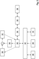
- Figure 2 shows schematically a method for the "bucket retain" function according to an embodiment of the present invention.
- a target grading angle ⁇ is obtained by means of an input device (e.g. a joystick or a button).
- This information 108 can be either a value of the target grading angle ⁇ or the command to keep the current grading angle ⁇ constant.
- sensor data 109 are recorded in order to record the position of the boom 4, 5 and the bucket 6.
- the weight 110 calculated during the weighing time is also recorded.
- a bus system 107 records all the information 108, 109 and 110 and transmits it to a control unit 103, which is responsible for controlling the third actuator 9.
- the control unit 103 can control the position 106 of the third actuator by means of a pump 104 and a main control valve 105.
- the control takes place in the loop 100, 101, 102, 103.
- the target inclination ⁇ of the holding element 6 is detected 100 during the movement of the at least one boom element 4, 5 and compared with the actual inclination ⁇ of the holding element 6 and the difference 101 is communicated to the control unit 103.
- the control unit 103 will then use the information 101 and the information acquired from the bus system 107 to generate a control signal for the main control valve 105.
- the signal is therefore calculated taking into account the weight of the load carried by the holding element 6.
- the information about the weight can be used, for example, as a control parameter in a gain scheduling or in a model-based control.
- Control parameters can also be selected depending on the positioning (e.g. the angle) of the boom 4, 5. This means different control parameters when guiding the bucket close to the main body 2 than when moving further away from the main body 2.
- the estimated load mass can also be used in other functions in which variable dynamics play a role. For example, in the workspace limitation assistance function.
- the core of the present invention is therefore that a further assistance function is used to estimate the current load mass in order to take this information into account in the control of the leveling angle.
- This can take the form of operating point-dependent control methods, such as gain scheduling, or a general, model-based approach. By combining the two functions, a better and operating point-independent control behavior is expected.
Landscapes
- Engineering & Computer Science (AREA)
- Mechanical Engineering (AREA)
- Mining & Mineral Resources (AREA)
- Civil Engineering (AREA)
- General Engineering & Computer Science (AREA)
- Structural Engineering (AREA)
- Life Sciences & Earth Sciences (AREA)
- General Life Sciences & Earth Sciences (AREA)
- Paleontology (AREA)
- Operation Control Of Excavators (AREA)
Description
- Die Erfindung betrifft ein Verfahren zum Steuern einer Arbeitsmaschine, das ermöglicht, eine Neigung eines Halteelements konstant zu behalten, während mindestens ein Auslegerelement bewegt wird .
- Mobile Arbeitsmaschinen mit Assistenzfunktion "Bucket Retain" sind weltweit benutzt. Eine solche Funktion ist in der Patentanmeldung
DE 11 2017 000 130 T5 offenbart. Die Assistenzfunktion "Bucket Retain" hat den Zweck einen eingestellten Planierwinkel einer Arbeitsmaschine zu regeln. Der Planierwinkel beschreibt den Winkel des Löffels in Bezug auf das äußere, übergeordnete Koordinatensystem und ist abhängig von Ausleger-, Stiel- und Löffelwinkel, in ihren jeweiligen Koordinatensystemen. Die Funktion "Bücket Retain" verstellt den Löffelwinkel geregelt um einen gewünschten Planierwinkel einzuhalten. Ausleger und Stiel sind weiterhin durch den Fahrzeugführer verstellbar. Weitere Arbeitsmaschinen mit Assistenzfunktion sind beispielsweise aus derJP 7 009600 B1 JP H10 259619 A - Eine solche Funktion kann Anwendungen bei verschiedenen Arten von Maschinen finden. In der Tat können Bagger (Standard, Mini, Midi, Mining, Mobil), Radlader, Telehandler, Forstmaschinen mit entsprechender Funktionalität auf dem Markt gefunden werden. In der vorliegenden Erfindung wird deswegen mit dem Wortlaut "Arbeitsmaschine" eine beliebige von dieser oder anderen aus dem Stand der Technik bekannten Maschine gemeint.
- Die Regelgenauigkeit und Regelgeschwindigkeit dieser Funktion ist aufgrund des unterschiedlichen Gewichtes des angebrachten Halteelements (zum Beispiel Zuladung in einem Löffel) und der damit verbundenen Dynamik allerdings nicht besonders hoch. Aus diesem Grund ist Zweck der Erfindung, die vorhandene Funktion zu verbessern.
- Gemäß einer Ausführungsform der vorliegenden Erfindung wird ein Verfahren zum Steuern einer Arbeitsmaschine bereitgestellt, die einen Hauptkörper und eine Bewegungsvorrichtung umfasst, die an dem Hauptkörper der Arbeitsmaschine angeschlossen ist und die konfiguriert ist Lasten aufzunehmen und bezüglich des Hauptkörpers zu bewegen, wobei die Bewegungsvorrichtung einen Ausleger mit einem oder mehreren Auslegerelementen und ein an einem Endabschnitt des Auslegers angeordnetes Halteelement zur Aufnahme von Last aufweist, wobei die Auslegerelemente und das Halteelement durch einen oder mehrere unabhängig voneinander wirkende Aktuatoren bewegbar sind, wobei Sensoren vorgesehen sind, die eingerichtet sind, Zustandsdaten der Bewegungsvorrichtung zu erfassen, wobei das Verfahren folgende Schritte umfasst:
- a. Erfassen einer Bewegung mindestens eines Auslegerelements;
- b. Erfassen eines Befehls, eine Soll-Neigung des Halteelements während der Bewegung des mindestens einen Auslegerelements konstant zu behalten, wobei die Soll-Neigung einen Soll-Winkel des Halteelements in einem Koordinatensystem, das unabhängig von dem mindestens einen Auslegerelement ist, beschreibt;
- c. Berechnen eines Gewichts einer von dem Halteelement aufgenommenen Last;
- d. Berechnen einer Soll-Bewegung eines der Aktuatoren, der für die Bewegung des Halteelements zuständig ist, sodass die Soll-Neigung des Halteelements während der Bewegung des mindestens einen Auslegerelements konstant bleibt, wobei die Berechnung unter Berücksichtigung des im Schritt c. berechneten Gewichts und der erfassten Bewegung des mindestens einen Auslegerelements erfolgt;
- e. Regeln des Aktuators, der für die Bewegung des Halteelements zuständig ist, auf Basis der im Schritt d. berechneten Soll-Bewegung.
- Die vorliegende Erfindung ist besonders vorteilhaft, da durch diese Funktion die Genauigkeit der "Bücket Retain" Funktion besonders erhört wird. Insbesondere haben das Testen der Funktion und Messungen am Bagger gezeigt, dass eine Verbesserung der Regelung bei Berücksichtigung der Last enorm ist. In derzeitiger Umsetzung wird ein linearer Regler für alle Arbeitspunkte, ohne Berücksichtigung der Last verwendet. Der Erfinder hat allerdings beobachtet, dass die Dynamik des Systems stark abhängig von Orientierung und Ladung des Löffels ist. Insbesondere hat der Erfinder beobachtet, dass optimale Regelparameter bei vollem Löffel stark von denen bei leerem Löffel abweichen. Wenn die aktuelle Ladung nicht berücksichtigt wird, kann lediglich ein Set an Regelparameter (als Kompromiss der verschiedenen Arbeitspunkte) verwendet werden. Eine solche Lösung verursacht allerdings enorme Ungenauigkeit, wie Schwingen und langzeitige Regelabweichungen, wenn verglichen mit der Genauigkeit, die ein Verfahren nach der vorliegenden Erfindung ermöglicht.
- Die vorliegende Erfindung wird unter Bezugnahme auf die beigefügten Figuren beschrieben, wobei sich gleiche Bezugszeichen auf gleiche Teile und / oder auf ähnliche Teile und / oder auf entsprechende Teile des Systems beziehen. Zu den Figuren:
-
Figur 1 zeigt schematisch eine Arbeitsmaschine mit beweglichen Elementen; -
Figur 2 zeigt schematisch ein Verfahren nach einer Ausführungsform der vorliegenden Erfindung. - Im Folgenden wird die vorliegende Erfindung unter Bezugnahme auf bestimmte Ausführungsformen beschrieben, wie sie in den beigefügten Figuren gezeigt sind. Nichtsdestotrotz ist die vorliegende Erfindung nicht auf die besonderen Ausführungsformen beschränkt, die in der folgenden detaillierten Beschreibung beschrieben und in den Figuren gezeigt sind, sondern die beschriebenen Ausführungsformen veranschaulichen lediglich einige Aspekte der vorliegenden Erfindung, deren Schutzbereich durch die Ansprüche definiert ist.
- Weitere Änderungen und Variationen der vorliegenden Erfindung sind für den Fachmann klar. Die vorliegende Beschreibung umfasst somit alle Änderungen und / oder Variationen der vorliegenden Erfindung, deren Schutzbereich durch die Ansprüche definiert ist.
-
Figur 1 zeigt einen Bagger 1 als Beispiel für eine Arbeitsmaschine. Der Bagger 1 weist einen Hauptkörper 2 und eine Bewegungsvorrichtung 3 auf, die an dem Hauptkörper 2 der Arbeitsmaschine 1 angeschlossen. Die Bewegungsvorrichtung ist konfiguriert Lasten aufzunehmen und bezüglich des Hauptkörpers 2 zu bewegen. Die Bewegungsvorrichtung 1 weist einen Ausleger auf, der wiederum mehrere Auslegerelemente aufweist, um ein Halteelement 6 zu bewegen. Die Auslegerelemente sind hier beispielhaft ein Hubarm 4 (oder einfach als "Ausleger" bekannt) und einen Arm 5 (oder auch als "Stiel" bekannt), die miteinander bzw. mit dem Hauptkörper 2 des Baggers 1 drehbar bzw. schwenkbar verbunden sind. Darüber hinaus umfasst der inFigur 1 dargestellte Bagger einen Löffel 6, der an einem Endabschnitt des Arms 5 angeordnet ist. Die Auslegerelemente 4, 5 und der Löffel sind mittels Aktuatoren 7, 8, 9 bewegbar, d.h. die Dreh- bzw. Schwenkbewegung um die Achsen wird durch eine Bewegung der Aktuatoren bewirkt. - Es ist ein erster Aktuator 7 für den Hubarm 4 vorgesehen, der die Bewegung bzw. Drehung des Hubarms 4 relativ zum Hauptkörper 2 bewirkt. Ebenso ist ein zweiter Aktuator 8 für den Arm 5 vorgesehen, der die Bewegung bzw. Drehung des Arms 4 relativ zum Hubarm 4 bewirkt. Ebenso ist ein dritter Aktuator 9 für den Löffel vorgesehen, der den Löffel (oder auch "Schaufel" genannt) bewegt bzw. dreht (kippt).
- Die Aktuatoren 7, 8, 9 können durch eine Steuerung angesteuert werden, wobei im Falle von Hydraulikzylindern Wegeventile vorgesehen sind, die den Fluss von Hydraulikflüssigkeit zu den Hydraulikzylindern steuern.
- Es sind Sensoren vorgesehen (in
Figur 1 nicht dargestellt), die Kräftedaten und Positionsdaten erfassen. Kräftedaten sind Daten bzw. Messdaten, die die von den Aktuatoren aufgebrachte Kräfte charakterisieren bzw. anzeigen. Dazu können insbesondere Drucksensoren verwendet werden, z.B. an den Hydraulikzylindern der Druck auf beiden Seiten des Kolbens gemessen werden, wobei dann die vom Hydraulikzylinder aufgebrachte Kraft durch die Druckdifferenz charakterisiert ist. Positionsdaten sind Daten bzw. Messdaten, die die Position (z.B. Winkel) der Auslegerelemente, insbesondere deren relative Position bzw. deren Position relativ zum Auslegerträger (insbesondere jeweils auch relative Winkel), charakterisieren bzw. anzeigen. Hierzu können insbesondere Winkelsensoren vorgesehen sein, oder Sensoren, die die Auslenkung der Hydraulikzylinder bestimmen. - Es wird insbesondere auf Kräftedaten und Positionsdaten und entsprechende Sensoren eingegangen. Dies sind bevorzugte Beispiele für Zustandsdaten bzw. Sensoren, im Allgemeinen können zusätzlich bzw. alternativ auch Zustandsdaten von anderen Sensoren erfasst werden, um beispielsweise Druckdaten, Momentdaten, Drehmomentdaten, Geschwindigkeitsdaten, Beschleunigungsdaten und/oder Spannungsdaten zu erfassen (die, wie angemerkt, im Prinzip auch als Kräfte- und/oder Positionsdaten aufgefasst werden können).
- Da die geometrischen Verhältnisse der Auslegerelemente und deren Gewichte bzw. Massen bekannt sind, kann aus den Kräfte- und Positionsdaten das Gewicht bzw. die Masse einer aufgenommenen Last berechnet bzw. geschätzt werden. Dazu wird eine sogenannte Wiegefunktion verwendet, deren Implementierung dem Fachmann an sich bekannt ist. Der Zeitpunkt oder Zeitraum, an bzw. in dem die Kräfte- und Positionsdaten erfasst werden, basierend auf denen die aufgenommene Last berechnet wird, wird als Wiegezeitpunkt bzw. Wiegezeitraum bezeichnet.
- Ein Beispiel einer Wiegefunktion ist in der Patendanmeldung
DE 102021205407.2 offenbart, die an dem Anmeldetag dieser Patentanmeldung noch nicht veröffentlicht wurde. - Wie in
Figur 1 dargestellt ist, entspricht der Winkel θa der Neigung des Hubarms 4 bezüglich einer horizontalen Ebene, der Winkel θb der Neigung des Arms 5 bezüglich der Achse des Hubarms 4, der Winkel θc der Neigung des Löffels 6 bezüglich der Achse des Armes 5. Der Winkel ϕ entspricht der Neigung des Löffels 6 bezüglich einer horizontalen Ebene. Der Winkel ϕ wird in einem Koordinatensystem dargestellt, das unabhängig von den anderen Auslegerelementen 4, 5 ist. - Das Ziel der vorliegenden Erfindung ist daher, den Winkel ϕ automatisch konstant zu behalten, während die anderen Winkeln θa und θb geändert werden. Der Planierwinkel ϕ wird deswegen (wenn die Funktion "Bücket Retain" aktiv ist) automatisch durch den dritten Aktuator 9 konstant gehalten.
-
Figur 2 zeigt schematisch ein Verfahren für die "Bücket Retain" Funktion nach einer Ausführungsform der vorliegenden Erfindung. - In einem ersten Schritt werden die Informationen über einen Soll Planierwinkel ϕ mittels einer Eingabevorrichtung (z.B. ein Joystick oder ein Knopf) erhalten. Diese Information 108 kann entweder ein Wert von dem Soll Planierwinkel ϕ oder der Befehl, den aktuellen ist Planierwinkel ϕ konstant zu behalten, sein. Darüber hinaus werden Sensordaten 109 erfasst, um die Position des Auslegers 4, 5 und des Löffels 6 zu erfassen. In dem ersten Schritt wird auch das während dem Wiegezeitpunkt berechnete Gewicht 110 erfasst. Ein Bus System 107 erfasst alle die Informationen 108, 109 und 110 und überträgt diese an eine Steuereinheit 103, die für die Regelung des dritten Aktuators 9 zuständig ist. Die Steuereinheit 103 kann mittels einer Pumpe 104 und eine Hauptsteuerventil 105 die Position 106 des dritten Aktuators steuern.
- Die Regelung erfolgt in dem Loop 100, 101, 102, 103. In einem ersten Schritt wird die Soll-Neigung ϕ des Halteelements 6 während der Bewegung des mindestens einen Auslegerelements 4, 5 erfasst 100 und mit der Ist-Neigung ϕ des Halteelements 6 verglichen und der Unterschied 101 wird an die Steuereinheit 103 mitgeteilt.
- Die Steuereinheit 103 wird dann die Information 101 und die von dem Bus System 107 erfassten Informationen benutzen, um ein Steuerungssignal für den Hauptsteuerventil 105 zu erzeugen.
- Das Signal wird deswegen unter Berücksichtigung des Gewichts der von dem Halteelement 6 aufgenommenen Last berechnet. Die Information über das Gewicht kann zum Beispiel als Regelparameter in einem Gain-Scheduling oder in einem Modellbasierte Regelung verwendet werden.
- Regelparameter können zusätzlich von der Positionierung (z.B. von dem Winkel) von dem Ausleger 4, 5 abhängig gewählt werden. D.h. unterschiedliche Regelparameter bei Führen des Löffels nahe an dem Hauptkörper 2 als bei Bewegung weiter von dem Hauptkörper 2 entfernt.
- Die geschätzte Ladungsmasse kann ebenfalls in anderen Funktionen genutzt werden, in denen die variable Dynamik eine Rolle spielen. Z.B. in der Assistenzfunktion Arbeitsraumbegrenzung.
- Der Kern der vorliegenden Erfindung besteht deswegen darin, dass eine weitere Assistenzfunktion, zum Schätzen der aktuellen Ladungsmasse, verwendet wird, um diese Information in der Regelung des Planierwinkels zu berücksichtigen. Dies kann in Form von arbeitspunktabhängigen Regelverfahren, wie z.B. Gain-Scheduling, oder einem allgemeinen, modellbasiertem Ansatz geschehen. Durch Kombination der beiden Funktionen wird ein besseres und arbeitspunktunabhängiges Regelverhalten erwartet.
Claims (9)
- Verfahren zum Steuern einer Arbeitsmaschine (1), die einen Hauptkörper (2) und eine Bewegungsvorrichtung (3) umfasst, die an dem Hauptkörper (2) der Arbeitsmaschine (1) angeschlossen ist und die konfiguriert ist Lasten aufzunehmen und bezüglich des Hauptkörpers (2) zu bewegen, wobei die Bewegungsvorrichtung einen Ausleger mit einem oder mehreren Auslegerelementen (4, 5) und ein an einem Endabschnitt des Auslegers angeordnetes Halteelement (6) zur Aufnahme von Last aufweist, wobei die Auslegerelemente (4, 5) und das Halteelement (6) durch einen oder mehrere unabhängig voneinander wirkende Aktuatoren (7, 8, 9) bewegbar sind, wobei Sensoren vorgesehen sind, die eingerichtet sind, Zustandsdaten der Bewegungsvorrichtung (3) zu erfassen, wobei das Verfahren folgende Schritte umfasst:a. Erfassen einer Bewegung mindestens eines Auslegerelements (4, 5);b. Erfassen eines Befehls, eine Soll-Neigung (ϕ) des Halteelements (6) während der Bewegung des mindestens einen Auslegerelements (4, 5) konstant zu behalten, wobei die Soll-Neigung (ϕ) einen Soll-Winkel des Halteelements (6) in einem Koordinatensystem, das unabhängig von dem mindestens einen Auslegerelement (4, 5) ist, beschreibt;c. Berechnen eines Gewichts einer von dem Halteelement (6) aufgenommenen Last;d. Berechnen einer Soll-Bewegung eines der Aktuatoren (9), der für die Bewegung des Halteelements (6) zuständig ist, sodass die Soll-Neigung (ϕ) des Halteelements (6) während der Bewegung des mindestens einen Auslegerelements (4, 5) konstant bleibt, wobei die Berechnung unter Berücksichtigung des im Schritt c. berechneten Gewichts und der erfassten Bewegung des mindestens einen Auslegerelements (4, 5) erfolgt;e. Regeln des Aktuators (9), der für die Bewegung des Halteelements zuständig ist, auf Basis der im Schritt d. berechneten Soll-Bewegung.
- Verfahren nach Anspruch 1 wobei das Halteelement (6) ein Löffel ist, und wobei die Soll-Neigung (ϕ) ein Soll-Planierwinkel des Löffels (6) ist.
- Verfahren nach einem der Ansprüche 1 oder 2, wobei der Ausleger ausschließlich ein erstes (4) und ein zweites (5) Auslegerelement umfasst.
- Verfahren nach einem der Ansprüche 1 bis 3, wobei in dem Schritt d. die Berechnung weiterhin unter Berücksichtigung der Position des Halteelements (6) bezüglich des Hauptkörpers (2) erfolgt.
- Verfahren nach einem der Ansprüche 1 bis 4, wobei in dem Schritt d. mindestens einen Regelparameter für die Berücksichtigung des im Schritt c. berechneten Gewichts benutzt wird, wobei der Regelparameter abhängig von der Position des Halteelements (6) ist.
- Recheneinheit, die dazu eingerichtet ist, ein Verfahren nach einem der vorstehenden Ansprüche durchzuführen.
- Arbeitsmaschine (1), die einen Hauptkörper (2) und eine Bewegungsvorrichtung (3) umfasst, die an dem Hauptkörper (2) der Arbeitsmaschine (1) angeschlossen ist und die konfiguriert ist Lasten aufzunehmen und bezüglich des Hauptkörpers (2) zu bewegen, wobei die Bewegungsvorrichtung einen Ausleger mit einem oder mehreren Auslegerelementen (4, 5) und ein an einem Endabschnitt des Auslegers angeordnetes Halteelement (6) zur Aufnahme von Last aufweist, wobei die Auslegerelemente (4, 5) und das Halteelement (6) durch einen oder mehrere unabhängig voneinander wirkende Aktuatoren (7, 8, 9) bewegbar sind, wobei Sensoren vorgesehen sind, die eingerichtet sind, Zustandsdaten der Bewegungsvorrichtung zu erfassen, wobei eine Steuerung vorgesehen ist, die eine Wiegefunktion implementiert, die dazu eingerichtet ist, erfasste Zustandsdaten auszuwerten, um ein Gewicht einer von der Bewegungsvorrichtung (3) aufgenommenen Last zu bestimmen; aufweisend eine Recheneinheit nach Anspruch 6.
- Computerprogramm, das eine Recheneinheit veranlasst, ein Verfahren nach einem der Ansprüche 1 bis 6 durchzuführen, wenn es auf der Recheneinheit ausgeführt wird.
- Maschinenlesbares Speichermedium mit einem darauf gespeicherten Computerprogramm nach Anspruch 8.
Applications Claiming Priority (1)
| Application Number | Priority Date | Filing Date | Title |
|---|---|---|---|
| DE102022203960.2A DE102022203960A1 (de) | 2022-04-25 | 2022-04-25 | Verfahren zur Verbesserung der Planierwinkelregelung einer Arbeitsmaschine |
Publications (2)
| Publication Number | Publication Date |
|---|---|
| EP4269705A1 EP4269705A1 (de) | 2023-11-01 |
| EP4269705B1 true EP4269705B1 (de) | 2025-01-01 |
Family
ID=86142693
Family Applications (1)
| Application Number | Title | Priority Date | Filing Date |
|---|---|---|---|
| EP23169142.9A Active EP4269705B1 (de) | 2022-04-25 | 2023-04-21 | Verfahren zur verbesserung der planierwinkelregelung einer arbeitsmaschine |
Country Status (4)
| Country | Link |
|---|---|
| EP (1) | EP4269705B1 (de) |
| JP (1) | JP2023161577A (de) |
| CN (1) | CN116950155A (de) |
| DE (1) | DE102022203960A1 (de) |
Family Cites Families (16)
| Publication number | Priority date | Publication date | Assignee | Title |
|---|---|---|---|---|
| DE4030954C2 (de) | 1990-09-29 | 1994-08-04 | Danfoss As | Verfahren zur Steuerung der Bewegung eines hydraulisch bewegbaren Arbeitsgeräts und Bahnsteuereinrichtung zur Durchführung des Verfahrens |
| JP3441886B2 (ja) | 1996-06-18 | 2003-09-02 | 日立建機株式会社 | 油圧建設機械の自動軌跡制御装置 |
| JP3653153B2 (ja) * | 1996-12-20 | 2005-05-25 | 新キャタピラー三菱株式会社 | 建設機械の制御装置 |
| JP3641096B2 (ja) * | 1997-03-18 | 2005-04-20 | 新キャタピラー三菱株式会社 | 建設機械の制御装置 |
| JP3608900B2 (ja) | 1997-03-10 | 2005-01-12 | 新キャタピラー三菱株式会社 | 建設機械の制御方法および制御装置 |
| DE19939796C1 (de) | 1999-08-21 | 2000-11-23 | Orenstein & Koppel Ag | Verfahren und Arbeitsmaschine zur Herstellung von Bodenflächen |
| WO2017086488A1 (ja) | 2016-11-29 | 2017-05-26 | 株式会社小松製作所 | 建設機械の制御装置及び建設機械の制御方法 |
| JP6856548B2 (ja) | 2017-01-10 | 2021-04-07 | 株式会社小松製作所 | 作業車両および制御方法 |
| JP7200124B2 (ja) | 2017-11-10 | 2023-01-06 | 住友建機株式会社 | ショベル |
| JP7141843B2 (ja) * | 2018-03-30 | 2022-09-26 | 株式会社小松製作所 | 作業機械の制御装置及び作業機械の制御方法 |
| JP7141894B2 (ja) | 2018-09-05 | 2022-09-26 | 日立建機株式会社 | 作業機械 |
| US11041291B2 (en) * | 2018-09-14 | 2021-06-22 | Deere & Company | Controlling a work machine based on sensed variables |
| NL2022360B1 (nl) | 2019-01-10 | 2020-08-13 | Hudson I P B V | Mobiele inrichting |
| DE102020212490A1 (de) | 2020-10-02 | 2022-04-07 | Robert Bosch Gesellschaft mit beschränkter Haftung | Verfahren zum Bestimmen des Gewichts einer Beladung einer mobilen Arbeitsmaschine, Lernverfahren für ein datenbasiertes Modell und mobile Arbeitsmaschine |
| JP7009600B1 (ja) * | 2020-12-07 | 2022-01-25 | 日立建機株式会社 | 作業機械 |
| DE102021205407A1 (de) | 2021-05-27 | 2022-12-01 | Robert Bosch Gesellschaft mit beschränkter Haftung | Verfahren zur Beladungsschätzung von Arbeitsmaschinen |
-
2022
- 2022-04-25 DE DE102022203960.2A patent/DE102022203960A1/de active Pending
-
2023
- 2023-04-21 EP EP23169142.9A patent/EP4269705B1/de active Active
- 2023-04-23 CN CN202310443955.3A patent/CN116950155A/zh active Pending
- 2023-04-24 JP JP2023070862A patent/JP2023161577A/ja active Pending
Also Published As
| Publication number | Publication date |
|---|---|
| JP2023161577A (ja) | 2023-11-07 |
| CN116950155A (zh) | 2023-10-27 |
| DE102022203960A1 (de) | 2023-10-26 |
| EP4269705A1 (de) | 2023-11-01 |
Similar Documents
| Publication | Publication Date | Title |
|---|---|---|
| AT514115B1 (de) | Elektrohydraulischer Steuerkreis | |
| EP2422018B1 (de) | Mobile arbeitsmaschine mit einer positionsregeleinrichtung eines arbeitsarms und verfahren zur positionsregelung eines arbeitsarms einer mobilen arbeitsmaschine | |
| DE102009037880B4 (de) | Mobile Arbeitsmaschine mit einer Regelvorrichtung mit einem Arbeitsarm und Verfahren zur Arbeitspunktregelung eines Arbeitsarms einer mobilen Arbeitsmaschine | |
| EP2843378B1 (de) | Arbeitsmaschine mit Hubvorrichtung und Wiegeeinrichtung | |
| EP2736833B1 (de) | Steuervorrichtung | |
| DE102020124867B4 (de) | Verbesserte Hydraulikvorrichtung | |
| DE112016000090T5 (de) | Baumaschinensteuerungssystem, baumaschine und baumaschinensteuerungsverfahren | |
| DE112016000072T5 (de) | Baumaschinensteuersystem, baumaschine und baumaschinensteuerverfahren | |
| EP3650179A1 (de) | System und verfahren zum bestimmen der masse einer von einem arbeitsgerät bewegten nutzlast | |
| DE102013017240A1 (de) | System zur Ermittlung des Arbeitszyklus | |
| DE112016000070T5 (de) | Arbeitsmaschinensteuersystem, arbeitsmaschine und arbeitsmaschinensteuerverfahren | |
| DE102019202746A1 (de) | Verfahren zum Begrenzen des Durchflusses als Reaktion auf den erfassten Druck | |
| EP4130394B1 (de) | Verfahren zur überwachung und/oder durchführung einer bewegung eines arbeitsgeräts sowie arbeitsgerät und computerprogrammprodukt | |
| WO2017174714A1 (de) | Kartesische steuerung einer mastspitze eines grossmanipulators, insbesondere betonpumpe | |
| DE102022120687A1 (de) | Arbeitsfahrzeuggabelausrichtungssystem und -verfahren | |
| DE3711239A1 (de) | Einrichtung zur sicherung von verfahrbaren ladegeraeten | |
| EP4148193B1 (de) | Verfahren zum aufrufen einer wiegefunktion einer arbeitsmaschine und arbeitsmaschine | |
| DE19510375A1 (de) | Nutzlastbestimmungssystem und Verfahren für eine Baggermaschine | |
| EP4269705B1 (de) | Verfahren zur verbesserung der planierwinkelregelung einer arbeitsmaschine | |
| WO2021239680A2 (de) | Verfahren zum betreiben einer mobilen arbeitsmaschine | |
| DE102021205386A1 (de) | Verfahren zum Betreiben eines hydraulischen Zylinders einer Arbeitsmaschine | |
| DE112023004528T5 (de) | Verfahren für ein betreiben eines arbeitsfahrzeugs gemäss einer maximal zulässigen schwenkgeschwindigkeit | |
| EP4269707B1 (de) | Verfahren zur lageschätzung einer arbeitskinematik einer arbeitsmaschine und arbeitsmaschine | |
| DE112022000038T5 (de) | Verfahren zur Schätzung eines Moments eines Arbeitsgerätes | |
| DE102023213198A1 (de) | Verfahren zur Bestimmung eines Gewichts einer durch einen Ausleger einer Arbeitsmaschine aufgenommenen Last |
Legal Events
| Date | Code | Title | Description |
|---|---|---|---|
| PUAI | Public reference made under article 153(3) epc to a published international application that has entered the european phase |
Free format text: ORIGINAL CODE: 0009012 |
|
| STAA | Information on the status of an ep patent application or granted ep patent |
Free format text: STATUS: THE APPLICATION HAS BEEN PUBLISHED |
|
| AK | Designated contracting states |
Kind code of ref document: A1 Designated state(s): AL AT BE BG CH CY CZ DE DK EE ES FI FR GB GR HR HU IE IS IT LI LT LU LV MC ME MK MT NL NO PL PT RO RS SE SI SK SM TR |
|
| STAA | Information on the status of an ep patent application or granted ep patent |
Free format text: STATUS: REQUEST FOR EXAMINATION WAS MADE |
|
| 17P | Request for examination filed |
Effective date: 20240502 |
|
| RBV | Designated contracting states (corrected) |
Designated state(s): AL AT BE BG CH CY CZ DE DK EE ES FI FR GB GR HR HU IE IS IT LI LT LU LV MC ME MK MT NL NO PL PT RO RS SE SI SK SM TR |
|
| GRAP | Despatch of communication of intention to grant a patent |
Free format text: ORIGINAL CODE: EPIDOSNIGR1 |
|
| STAA | Information on the status of an ep patent application or granted ep patent |
Free format text: STATUS: GRANT OF PATENT IS INTENDED |
|
| INTG | Intention to grant announced |
Effective date: 20241017 |
|
| RIN1 | Information on inventor provided before grant (corrected) |
Inventor name: EHLERS, BENJAMIN Inventor name: GRIESER, ARMIN |
|
| GRAS | Grant fee paid |
Free format text: ORIGINAL CODE: EPIDOSNIGR3 |
|
| GRAA | (expected) grant |
Free format text: ORIGINAL CODE: 0009210 |
|
| STAA | Information on the status of an ep patent application or granted ep patent |
Free format text: STATUS: THE PATENT HAS BEEN GRANTED |
|
| AK | Designated contracting states |
Kind code of ref document: B1 Designated state(s): AL AT BE BG CH CY CZ DE DK EE ES FI FR GB GR HR HU IE IS IT LI LT LU LV MC ME MK MT NL NO PL PT RO RS SE SI SK SM TR |
|
| REG | Reference to a national code |
Ref country code: GB Ref legal event code: FG4D Free format text: NOT ENGLISH |
|
| REG | Reference to a national code |
Ref country code: CH Ref legal event code: EP |
|
| REG | Reference to a national code |
Ref country code: DE Ref legal event code: R096 Ref document number: 502023000440 Country of ref document: DE |
|
| REG | Reference to a national code |
Ref country code: IE Ref legal event code: FG4D Free format text: LANGUAGE OF EP DOCUMENT: GERMAN |
|
| REG | Reference to a national code |
Ref country code: LT Ref legal event code: MG9D |
|
| REG | Reference to a national code |
Ref country code: NL Ref legal event code: MP Effective date: 20250101 |
|
| PG25 | Lapsed in a contracting state [announced via postgrant information from national office to epo] |
Ref country code: NL Free format text: LAPSE BECAUSE OF FAILURE TO SUBMIT A TRANSLATION OF THE DESCRIPTION OR TO PAY THE FEE WITHIN THE PRESCRIBED TIME-LIMIT Effective date: 20250101 |
|
| PG25 | Lapsed in a contracting state [announced via postgrant information from national office to epo] |
Ref country code: FI Free format text: LAPSE BECAUSE OF FAILURE TO SUBMIT A TRANSLATION OF THE DESCRIPTION OR TO PAY THE FEE WITHIN THE PRESCRIBED TIME-LIMIT Effective date: 20250101 |
|
| PG25 | Lapsed in a contracting state [announced via postgrant information from national office to epo] |
Ref country code: PL Free format text: LAPSE BECAUSE OF FAILURE TO SUBMIT A TRANSLATION OF THE DESCRIPTION OR TO PAY THE FEE WITHIN THE PRESCRIBED TIME-LIMIT Effective date: 20250101 |
|
| PGFP | Annual fee paid to national office [announced via postgrant information from national office to epo] |
Ref country code: DE Payment date: 20250624 Year of fee payment: 3 |
|
| PG25 | Lapsed in a contracting state [announced via postgrant information from national office to epo] |
Ref country code: ES Free format text: LAPSE BECAUSE OF FAILURE TO SUBMIT A TRANSLATION OF THE DESCRIPTION OR TO PAY THE FEE WITHIN THE PRESCRIBED TIME-LIMIT Effective date: 20250101 |
|
| PG25 | Lapsed in a contracting state [announced via postgrant information from national office to epo] |
Ref country code: IS Free format text: LAPSE BECAUSE OF FAILURE TO SUBMIT A TRANSLATION OF THE DESCRIPTION OR TO PAY THE FEE WITHIN THE PRESCRIBED TIME-LIMIT Effective date: 20250501 Ref country code: NO Free format text: LAPSE BECAUSE OF FAILURE TO SUBMIT A TRANSLATION OF THE DESCRIPTION OR TO PAY THE FEE WITHIN THE PRESCRIBED TIME-LIMIT Effective date: 20250401 |
|
| PGFP | Annual fee paid to national office [announced via postgrant information from national office to epo] |
Ref country code: IT Payment date: 20250430 Year of fee payment: 3 |
|
| PG25 | Lapsed in a contracting state [announced via postgrant information from national office to epo] |
Ref country code: HR Free format text: LAPSE BECAUSE OF FAILURE TO SUBMIT A TRANSLATION OF THE DESCRIPTION OR TO PAY THE FEE WITHIN THE PRESCRIBED TIME-LIMIT Effective date: 20250101 |
|
| PG25 | Lapsed in a contracting state [announced via postgrant information from national office to epo] |
Ref country code: LV Free format text: LAPSE BECAUSE OF FAILURE TO SUBMIT A TRANSLATION OF THE DESCRIPTION OR TO PAY THE FEE WITHIN THE PRESCRIBED TIME-LIMIT Effective date: 20250101 Ref country code: PT Free format text: LAPSE BECAUSE OF FAILURE TO SUBMIT A TRANSLATION OF THE DESCRIPTION OR TO PAY THE FEE WITHIN THE PRESCRIBED TIME-LIMIT Effective date: 20250502 |
|
| PG25 | Lapsed in a contracting state [announced via postgrant information from national office to epo] |
Ref country code: GR Free format text: LAPSE BECAUSE OF FAILURE TO SUBMIT A TRANSLATION OF THE DESCRIPTION OR TO PAY THE FEE WITHIN THE PRESCRIBED TIME-LIMIT Effective date: 20250402 Ref country code: BG Free format text: LAPSE BECAUSE OF FAILURE TO SUBMIT A TRANSLATION OF THE DESCRIPTION OR TO PAY THE FEE WITHIN THE PRESCRIBED TIME-LIMIT Effective date: 20250101 |
|
| PGFP | Annual fee paid to national office [announced via postgrant information from national office to epo] |
Ref country code: AT Payment date: 20250721 Year of fee payment: 3 |
|
| PG25 | Lapsed in a contracting state [announced via postgrant information from national office to epo] |
Ref country code: CZ Free format text: LAPSE BECAUSE OF FAILURE TO SUBMIT A TRANSLATION OF THE DESCRIPTION OR TO PAY THE FEE WITHIN THE PRESCRIBED TIME-LIMIT Effective date: 20250101 |
|
| PG25 | Lapsed in a contracting state [announced via postgrant information from national office to epo] |
Ref country code: SE Free format text: LAPSE BECAUSE OF FAILURE TO SUBMIT A TRANSLATION OF THE DESCRIPTION OR TO PAY THE FEE WITHIN THE PRESCRIBED TIME-LIMIT Effective date: 20250101 |
|
| REG | Reference to a national code |
Ref country code: DE Ref legal event code: R097 Ref document number: 502023000440 Country of ref document: DE |
|
| PG25 | Lapsed in a contracting state [announced via postgrant information from national office to epo] |
Ref country code: SM Free format text: LAPSE BECAUSE OF FAILURE TO SUBMIT A TRANSLATION OF THE DESCRIPTION OR TO PAY THE FEE WITHIN THE PRESCRIBED TIME-LIMIT Effective date: 20250101 |
|
| PG25 | Lapsed in a contracting state [announced via postgrant information from national office to epo] |
Ref country code: DK Free format text: LAPSE BECAUSE OF FAILURE TO SUBMIT A TRANSLATION OF THE DESCRIPTION OR TO PAY THE FEE WITHIN THE PRESCRIBED TIME-LIMIT Effective date: 20250101 |
|
| PG25 | Lapsed in a contracting state [announced via postgrant information from national office to epo] |
Ref country code: EE Free format text: LAPSE BECAUSE OF FAILURE TO SUBMIT A TRANSLATION OF THE DESCRIPTION OR TO PAY THE FEE WITHIN THE PRESCRIBED TIME-LIMIT Effective date: 20250101 |
|
| PG25 | Lapsed in a contracting state [announced via postgrant information from national office to epo] |
Ref country code: RO Free format text: LAPSE BECAUSE OF FAILURE TO SUBMIT A TRANSLATION OF THE DESCRIPTION OR TO PAY THE FEE WITHIN THE PRESCRIBED TIME-LIMIT Effective date: 20250101 |
|
| PG25 | Lapsed in a contracting state [announced via postgrant information from national office to epo] |
Ref country code: SK Free format text: LAPSE BECAUSE OF FAILURE TO SUBMIT A TRANSLATION OF THE DESCRIPTION OR TO PAY THE FEE WITHIN THE PRESCRIBED TIME-LIMIT Effective date: 20250101 |
|
| PLBE | No opposition filed within time limit |
Free format text: ORIGINAL CODE: 0009261 |
|
| STAA | Information on the status of an ep patent application or granted ep patent |
Free format text: STATUS: NO OPPOSITION FILED WITHIN TIME LIMIT |
|
| 26N | No opposition filed |
Effective date: 20251002 |
|
| PG25 | Lapsed in a contracting state [announced via postgrant information from national office to epo] |
Ref country code: LU Free format text: LAPSE BECAUSE OF NON-PAYMENT OF DUE FEES Effective date: 20250421 |
|
| PG25 | Lapsed in a contracting state [announced via postgrant information from national office to epo] |
Ref country code: MC Free format text: LAPSE BECAUSE OF FAILURE TO SUBMIT A TRANSLATION OF THE DESCRIPTION OR TO PAY THE FEE WITHIN THE PRESCRIBED TIME-LIMIT Effective date: 20250101 |
|
| REG | Reference to a national code |
Ref country code: BE Ref legal event code: MM Effective date: 20250430 |
|
| PG25 | Lapsed in a contracting state [announced via postgrant information from national office to epo] |
Ref country code: FR Free format text: LAPSE BECAUSE OF NON-PAYMENT OF DUE FEES Effective date: 20250430 |
|
| PG25 | Lapsed in a contracting state [announced via postgrant information from national office to epo] |
Ref country code: BE Free format text: LAPSE BECAUSE OF NON-PAYMENT OF DUE FEES Effective date: 20250430 |