EP4265878B1 - Türanordnung - Google Patents
Türanordnung Download PDFInfo
- Publication number
- EP4265878B1 EP4265878B1 EP22168852.6A EP22168852A EP4265878B1 EP 4265878 B1 EP4265878 B1 EP 4265878B1 EP 22168852 A EP22168852 A EP 22168852A EP 4265878 B1 EP4265878 B1 EP 4265878B1
- Authority
- EP
- European Patent Office
- Prior art keywords
- door
- drive rod
- door leaf
- drop seal
- locking device
- Prior art date
- Legal status (The legal status is an assumption and is not a legal conclusion. Google has not performed a legal analysis and makes no representation as to the accuracy of the status listed.)
- Active
Links
Images

Classifications
-
- E—FIXED CONSTRUCTIONS
- E06—DOORS, WINDOWS, SHUTTERS, OR ROLLER BLINDS IN GENERAL; LADDERS
- E06B—FIXED OR MOVABLE CLOSURES FOR OPENINGS IN BUILDINGS, VEHICLES, FENCES OR LIKE ENCLOSURES IN GENERAL, e.g. DOORS, WINDOWS, BLINDS, GATES
- E06B7/00—Special arrangements or measures in connection with doors or windows
- E06B7/16—Sealing arrangements on wings or parts co-operating with the wings
- E06B7/18—Sealing arrangements on wings or parts co-operating with the wings by means of movable edgings, e.g. draught sealings additionally used for bolting, e.g. by spring force or with operating lever
- E06B7/20—Sealing arrangements on wings or parts co-operating with the wings by means of movable edgings, e.g. draught sealings additionally used for bolting, e.g. by spring force or with operating lever automatically withdrawn when the wing is opened, e.g. by means of magnetic attraction, a pin or an inclined surface, especially for sills
- E06B7/21—Sealing arrangements on wings or parts co-operating with the wings by means of movable edgings, e.g. draught sealings additionally used for bolting, e.g. by spring force or with operating lever automatically withdrawn when the wing is opened, e.g. by means of magnetic attraction, a pin or an inclined surface, especially for sills with sealing strip movable in plane of wing
-
- E—FIXED CONSTRUCTIONS
- E06—DOORS, WINDOWS, SHUTTERS, OR ROLLER BLINDS IN GENERAL; LADDERS
- E06B—FIXED OR MOVABLE CLOSURES FOR OPENINGS IN BUILDINGS, VEHICLES, FENCES OR LIKE ENCLOSURES IN GENERAL, e.g. DOORS, WINDOWS, BLINDS, GATES
- E06B7/00—Special arrangements or measures in connection with doors or windows
- E06B7/16—Sealing arrangements on wings or parts co-operating with the wings
- E06B7/18—Sealing arrangements on wings or parts co-operating with the wings by means of movable edgings, e.g. draught sealings additionally used for bolting, e.g. by spring force or with operating lever
- E06B7/20—Sealing arrangements on wings or parts co-operating with the wings by means of movable edgings, e.g. draught sealings additionally used for bolting, e.g. by spring force or with operating lever automatically withdrawn when the wing is opened, e.g. by means of magnetic attraction, a pin or an inclined surface, especially for sills
- E06B7/215—Sealing arrangements on wings or parts co-operating with the wings by means of movable edgings, e.g. draught sealings additionally used for bolting, e.g. by spring force or with operating lever automatically withdrawn when the wing is opened, e.g. by means of magnetic attraction, a pin or an inclined surface, especially for sills with sealing strip being moved to a retracted position by elastic means, e.g. springs
-
- E—FIXED CONSTRUCTIONS
- E06—DOORS, WINDOWS, SHUTTERS, OR ROLLER BLINDS IN GENERAL; LADDERS
- E06B—FIXED OR MOVABLE CLOSURES FOR OPENINGS IN BUILDINGS, VEHICLES, FENCES OR LIKE ENCLOSURES IN GENERAL, e.g. DOORS, WINDOWS, BLINDS, GATES
- E06B7/00—Special arrangements or measures in connection with doors or windows
- E06B7/16—Sealing arrangements on wings or parts co-operating with the wings
- E06B7/18—Sealing arrangements on wings or parts co-operating with the wings by means of movable edgings, e.g. draught sealings additionally used for bolting, e.g. by spring force or with operating lever
- E06B7/20—Sealing arrangements on wings or parts co-operating with the wings by means of movable edgings, e.g. draught sealings additionally used for bolting, e.g. by spring force or with operating lever automatically withdrawn when the wing is opened, e.g. by means of magnetic attraction, a pin or an inclined surface, especially for sills
- E06B2007/202—Actuator connected to wing frame
Definitions
- the invention relates to a door arrangement with the features of the preamble of claim 1.
- the sealing device described therein has a U-shaped rail, a sealing strip that can be moved within it, an actuating rod that protrudes from the front of the U-shaped rail, and leaf springs that preload the sealing strip into the retracted position.
- the actuating rod comes into contact with the door frame when the door leaf is closed, the leaf springs are compressed and the sealing strip is lowered.
- the leaf springs are relaxed again and the sealing strip is raised.
- the disadvantage of this is that the displacement of the sealing strip is forcibly coupled with the pivoting movement of the door leaf. As a result, the sealing strip is not raised sufficiently when the door leaf is opened at small angles and therefore touches the floor. In addition to damaging the floor in the area of the door arrangement, this also damages the sealing strip, which impairs the sealing effect.
- a sealing strip does not come into contact with the floor until later when the door leaf is closed, possibly only when the door leaf is in the closed position. This reduces wear on the floor when the door leaf is closed. However, these lowering delays have no effect when the door leaf is opened, so damage can still occur if the sealing strip drags on the floor.
- US 10,167,666 B2 shows a sealing system for windows with a latch, a connecting rod and a gear acting on a first rod which is connected via triangular elements to a second rod with a sealing element. If the first rod is moved relative to the second rod, the second rod with the sealing element is lowered to the ground.
- JP H09 78958 A shows a door arrangement according to the preamble of claim 1 and shows a shield of the lower door edge with a similar structure. There, the movement of a rod is converted via two movement conversion mechanisms into a movement of a sealing element sealing a door gap.
- EP 2 063 060 A2 discloses a seal with a lowerable sealing strip, wherein a horizontal movement of a coupling element is converted into a vertical movement of a sealing strip.
- the invention is based on the object of reducing wear on door assemblies with door bottom seals.
- wear on the floor and door bottom seal when opening a door leaf of the door assembly should be reduced or completely avoided.
- the invention solves this problem by a door arrangement having the features of claim 1.
- the door arrangement has a door frame and a door leaf that is pivotably mounted on the door frame and can be pivoted relative to the door frame between a closed position (door closed) and an open position (door leaf pivoted relative to the door frame).
- the door leaf has a locking device for locking the door leaf (in the closed position) to the door frame and a door bottom seal with a movable sealing element for sealing a gap on the underside of the door leaf to the floor or subsurface.
- the sealing element can be moved between a raised position and a lowered position relative to the underside of the door leaf or to the door bottom seal by means of a drive mechanism.
- the locking device has a drive rod and the locking device is coupled to the door bottom seal via the drive rod in such a way that when the locking device is unlocked in the closed position of the door leaf, the sealing element is raised before the door leaf is pivoted out of the lowered position.
- the locking device is coupled to the door bottom seal via the drive rod in such a way that when the locking device is unlocked in the closed position of the door leaf, the sealing element is released from the lowered position before the door leaf can be pivoted.
- the locking device can be designed in such a way that when the locking device is unlocked, the sealing element is raised from the floor, for example with an air gap of one or more millimeters, before one or more locking elements of the locking device, which lock the door leaf to the door frame, release the door leaf for pivoting (door opening) or reach their release position.
- the proposed design of the door arrangement has the advantage that the sealing element is raised from the lowered position before the door is opened or before the door leaf is pivoted from the closed position and the associated unlocking, and thus no longer has contact with the floor. This means that there are no grinding marks on the floor and therefore no wear on the sealing element or a sealing lip of the sealing element caused by the opening process.
- the door bottom seal can also be referred to as a bottom door seal.
- the door bottom seal is a sealing arrangement for sealing a gap between the bottom of the door leaf and the floor or subsurface ("bottom door gap").
- the gap is a door gap or air gap on the bottom of the door leaf.
- the door bottom seal is in particular designed and/or intended to be attached to the underside of a door leaf, for example bluntly (direct attachment to the underside of the door leaf) or in a groove formed on the underside of the door leaf.
- the sealing element no longer has contact with the floor or subsurface (no sealing) and the door leaf can be pivoted.
- the raised position can also be referred to as the door leaf pivot position.
- the sealing element rests on the floor or subsurface (sealing is achieved).
- the lowered position can also be referred to as the sealing position.
- the door bottom seal is movably attached to the underside of the door leaf, so that the door bottom seal can be moved along the longitudinal direction of the underside of the door leaf.
- the drive mechanism is pre-tensioned, in particular by means of one or more spring elements, in such a way that the sealing element is forced into the raised position or should be forced into it.
- a plunger protrudes at least partially (from the door bottom seal) on the front side, whereby the plunger comes into contact with the door frame when the door leaf is pivoted into the closed position and is subjected to a force by it.
- the plunger therefore acts in such a way on the drive mechanism so that the sealing element is moved into the lowered position and the door bottom seal is pre-tensioned in the direction of the drive rod (ie for a displacement in the direction of the drive rod).
- the movable mounting of the door bottom seal and its pre-tension in the direction of the drive rod facilitates a later lifting of the sealing element.
- a damping device can be connected between the tappet and the drive mechanism, in particular between the tappet and a bearing element designed as a floating bearing (described below), to delay the lowering of the sealing element. This can reduce or prevent any wear on the base and sealing element when the door leaf is closed.
- the damping device can be a hydraulic or pneumatic damper, for example.
- a spacer can be attached to the free end of the drive rod facing the door bottom seal, which is arranged in a free space between a lock faceplate of the locking device and the end of the door bottom seal facing the drive rod (opposite hinge side) when the door leaf is in the closed position.
- the drive rod is coupled to the locking device in such a way that when the locking device is unlocked (drive rod is retracted or raised and thus) the spacer is pulled out of the free space, so that as a result of the pre-tensioning of the door bottom seal towards the drive rod, the The door bottom seal is moved towards the lock faceplate, whereby the sealing element is raised from the lowered position.
- the sealing element is raised from the lowered position independently of the pivoting of the door leaf. Rather, this lifting is caused by the pre-tensioned drive mechanism, which moves the door bottom seal after the spacer is pulled out of the free space, whereby the sealing element is raised from the lowered position.
- the drive mechanism can have two bearing elements coupled to the door bottom seal (or its housing, e.g. a carrier profile), on each of which a coupling rod is pivotally mounted and preloaded relative to the bearing element by means of a spring, in particular a tension spring, wherein the coupling rods are each pivotally coupled to the sealing element at the free end (end facing away from the bearing element).
- a spring in particular a tension spring
- one of the bearing elements can be arranged in a section of the door bottom seal facing the drive rod and designed as a fixed bearing (immovable relative to the door bottom seal along its longitudinal direction, for example fastened relative to the door bottom seal with a corresponding fastening element, in particular a screw).
- the other bearing element can be arranged in a section of the door bottom seal facing away from the drive rod.
- Door bottom seal and guided as a movable bearing whereby the movable bearing can be moved along the longitudinal direction of the door bottom seal by applying pressure to it with the tappet (the movable bearing can be moved relative to the door bottom seal or its housing). This contributes to a simple and even lowering of the sealing element.
- This lowering is brought about in particular by the tappet, as this moves the movable bearing towards the fixed bearing and by connecting the coupling rods, whose coupling to the sealing element (distance of the pivot axes on the sealing element) in particular has a constant distance, both coupling rods are pivoted and thus the sealing element is lowered.
- the movable bearing can be guided so as to be displaceable in a corresponding profile section of the housing of the door bottom seal, e.g. a carrier profile.
- the drive mechanism can have a spring device (arranged in the door bottom seal or in its housing), in particular a leaf spring device.
- the spring device can be attached to the door bottom seal at one end facing the drive rod (opposite hinge side), coupled to the tappet at the other end (hinge side) and coupled to the sealing element between its two ends (or in an area in between).
- the drive rod can have a first section that is coupled (directly or indirectly) to the locking device (e.g. a main lock of the locking device), and a second section (separate from the first section) to which the spacer is attached.
- the first section and the second section can each have a rear grip section, via which the first section and the second section engage behind one another (positively), with a freewheel section adjoining the rear grip section (away from the free end) so that the first section and the second section of the drive rod can be moved relative to one another.
- the rear grip sections e.g.
- a compression spring can be provided which rests directly or indirectly on the door leaf or the lock faceplate at one end and on the second section of the drive rod or the spacer.
- the compression spring pre-tensions the second section of the drive rod relative to the door leaf or the first section (in the extension direction). This forces the spacer into the free space.
- the sections of the drive rod are forced into the extended position relative to one another.
- a further compression spring can be expediently provided, which rests at one end on the lock faceplate and at the other end on an end of the door bottom seal facing the lock faceplate. This allows the door bottom seal to be reset by moving it away from the drive rod or the lock faceplate (towards the side opposite the hinge) after the spacer has been moved out of the free space and the door bottom seal has been moved towards the drive rod or the lock faceplate.
- the further compression spring thus serves as a return spring.
- the door bottom seal is moved along the longitudinal direction of the underside of the door leaf away from the lock faceplate or towards the hinge side by means of the additional compression spring.
- the spacer can thus get back into the gap, for example after the locking device has been activated (e.g. releasing a door handle).
- a mounting bracket for attaching the sealing arrangement can serve as a displacement stop. Recess in the end piece to hold the additional compression spring.
- the door bottom seal can have a support profile which has a longitudinally extending groove (C-groove) on two of the profile's long sides adjacent to the profile side facing the door leaf (when installed).
- One or more guide parts are provided which are attached to the underside of the door leaf using fastening elements (e.g. screws) and which each engage in the groove on the profile's long sides.
- the door bottom seal is thus slidably mounted along the longitudinal direction of the underside of the door leaf, but is held securely orthogonally to this (along the direction of gravity).
- the door bottom seal can advantageously be attached to the end of the door leaf facing away from the drive rod (hinge side) using a mounting bracket that limits the movement of the door bottom seal away from the drive rod (or towards the hinge side).
- the mounting bracket thus serves as a displacement stop.
- a first leg of the mounting bracket extends along the front side of the door leaf.
- a second leg of the mounting bracket extends along the bottom of the door leaf along the door bottom seal or engages the door bottom seal.
- the mounting bracket is attached to the door leaf, in particular screwed.
- the sealing element can have a sealing body and a sealing lip attached to it.
- the sealing lip is easily mounted in the sealing body by the sealing body, to which the sealing lip is held, so that the sealing element or the sealing lip can be raised and lowered.
- the sealing body can be designed as an extruded profile, e.g. made of light metal.
- the sealing body can have a holder for the sealing lip, to or in which the sealing lip can be attached.
- the sealing lip can be made of plastic or rubber.
- the locking device can expediently have a main lock which can be operated via a door handle and/or a locking cylinder and is coupled to the drive rod, in particular via a lock mechanism, so that the drive rod can be driven when the main lock is operated.
- the door handle can be coupled to a lock nut which is rotatably mounted in the main lock.
- the locking cylinder can be a profile cylinder arranged in the main lock.
- the main lock can have a latch and/or a lock bolt as locking elements. This enables the door leaf to be reliably locked to the door frame.
- the locking device can have one or more secondary locks, which are connected to the Drive rods are coupled, whereby the secondary locks each have a latch bolt (pre-tensioned in relation to the locking position) and/or a swivel bolt.
- the secondary locks can be coupled to the main lock by means of the drive rod, so that the secondary locks can be actuated by means of the main lock, in particular for unlocking the locking device.
- the locking device can optionally be designed as a multi-point locking system.
- FIG 1 shows a door arrangement which is designated overall by the reference numeral 10 (shown only in a partial sectional view).
- the door arrangement 10 has a door frame 12 and a door leaf 14 pivotably mounted on the door frame 12.
- the door leaf 14 can be pivoted relative to the door frame 12 between a closed position and an open position.
- the door leaf 14 is pivotably mounted on the door frame 12 on a hinge side 16 by means of door hinges (not shown).
- the door leaf 14 has a locking device 20 for locking the door leaf 14 in the closed position on the door frame 12.
- the locking device 20 is arranged on a hinge side 22 of the door leaf 14.
- the door leaf 14 also has a door bottom seal 24 with a movable sealing element 26 for sealing a gap 28 on the underside 30 of the door leaf towards the floor 32.
- a "blunt" installation of the door bottom seal 24 on the underside 30 of the door leaf is possible, the door bottom seal 24 in the example is arranged in a groove 31 formed on the underside 30 of the door leaf.
- the sealing element 26 of the door bottom seal 24 is movable by means of a drive mechanism 34 relative to the door leaf underside 30 between a raised position (door leaf pivot position; cf. Fig. 4b ) and a lowered position (sealing position; cf. Fig.1 or Fig.4a ) can be relocated.
- the locking device 20 has a drive rod 36 and is coupled to the door bottom seal 24 via the drive rod 36 in such a way that when the locking device 20 is unlocked in the closed position of the door leaf 14, the sealing element 26 is raised from the lowered position before the door leaf 14 is pivoted (cf. Fig.4a and 4b ).
- the door bottom seal 24 is slidably attached to the door leaf underside 30 so that the door bottom seal 24 can be moved along the longitudinal direction 38 of the door leaf underside 30.
- the drive mechanism 34 is pre-tensioned so that the sealing element 26 is forced into the raised position.
- At the end of the drive rod 36 facing away from the Door bottom seal 24 (hinge side 16) has a plunger 40 protruding at least partially from the front of the door bottom seal 24, whereby the plunger 40 comes into contact with the door frame 12 when the door leaf 14 is pivoted into the closed position and is subjected to a force by the latter.
- the plunger 40 acts on the drive mechanism 34 in such a way that the sealing element 26 is displaced into the lowered position and the door bottom seal 24 is pre-tensioned in the direction of the drive rod 36 (i.e. towards the opposite hinge side 22).
- a damping device for delaying the lowering can be connected between the plunger and the drive mechanism 34, in particular a bearing element 52 designed as a floating bearing, as described above.
- a spacer 42 is attached to the free end of the drive rod 36 facing the door bottom seal 24, which, when the door leaf 14 is in the closed position, is arranged in a free space 44 between a lock faceplate 46 of the locking device 20 and the end of the door bottom seal 24 (opposite hinge side 22) facing the drive rod 36 (cf. Fig.1 and 4a ).
- the drive rod 36 is coupled to the locking device 20 in such a way that when the locking device 20 is unlocked (drive rod 36 is retracted or raised), the spacer 42 is pulled out of the free space 44 so that, as a result of the pre-tensioning of the door bottom seal 24 towards the drive rod 36, the door bottom seal 24 is displaced towards the lock faceplate 46, whereby the sealing element 26 is raised from the lowered position (cf. Fig.4b ).
- the drive mechanism 34 has two bearing elements 50, 52 coupled to the door bottom seal 24, on each of which a coupling rod 54, 56 is pivotally mounted and is prestressed relative to the bearing element 50, 52 by means of a spring 58, 60, in the example a tension spring, wherein the coupling rods 54, 56 are each pivotally coupled to the sealing element 26 at the free end (end facing away from the bearing element 50, 52) (cf. Fig.1 ).
- the bearing element 50 is arranged in a section of the door bottom seal 24 facing the drive rod 36 and is designed as a fixed bearing.
- the bearing element 50 is immovable relative to the door bottom seal 24 along its longitudinal direction 38 and is fastened relative to the door bottom seal 24 with a fastening element 62, in the example with a screw.
- the other bearing element 52 is arranged in a section of the door bottom seal 24 facing away from the drive rod 36 and is guided therein as a movable bearing, wherein the movable bearing can be moved along the longitudinal direction 38 of the door bottom seal 24 by being acted upon by the tappet 40.
- the movable bearing can be guided in a corresponding profile section of the housing of the door bottom seal 24, for example a carrier profile 84.
- the drive mechanism 34 can have a leaf spring device, as described above.
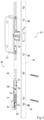
- the drive rod 36 has a first portion 64 which is coupled to the locking device 20 (e.g. a main lock of the locking device) and a separate second portion 66 to which the spacer 42 is attached (cf. Fig.3 ).
- the first section 64 and the second section 66 each have a rear grip section 68, 70, via which the first section 64 and the second section 66 engage behind one another, with a freewheel section 72, 74 adjoining the rear grip section 68, 70 so that the first section 64 and the second section 66 of the drive rod 36 can be moved relative to one another.
- the rear grip sections 68, 70 e.g.
- a compression spring 76 is provided, which at one end rests directly or indirectly on the door leaf 14 or on the lock face 46 and at the other end rests on the second section 66 of the drive rod 36 or on the spacer 42 (cf. Fig.1 and 3 ).
- the compression spring 76 pre-tensions the second section 66 of the drive rod 36 relative to the door leaf 14 or the first section 64 (in the extension direction).
- the compression spring 76 is arranged in a corresponding receptacle 77, which is fastened to the face plate 46 by means of a screw 78.
- a further compression spring 80 is also provided, which rests at one end on the lock faceplate 46 and at the other end on an end of the door bottom seal 24 facing the lock faceplate 46 (cf. Fig.1 and 2 ). This allows the door bottom seal 24 to be reset by moving it away from the drive rod 36 or the lock faceplate 46 (towards the opposite hinge side 22) after the spacer 42 has been moved away from the free space 44 and the door bottom seal 24 has been moved towards the drive rod 36 or the lock faceplate 46 (cf. Fig.5b ).
- the additional compression spring 80 thus serves as a return spring.
- the compression spring 80 is held on the door bottom seal 24 by means of a holding body or release body 82 (cf. Fig.1 and 2 ).
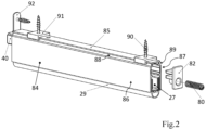
- the door bottom seal 24 has a carrier profile 84 which, adjacent to the profile side 85 facing the door leaf 14 (in the assembled state), has a longitudinally extending groove 88, 89 (in the example a C-groove) on two profile longitudinal sides 86, 87 (cf. Fig.2 ).
- One or more guide parts 91 are provided which are fastened to the underside 30 of the door leaf by means of fastening elements 90 (e.g. screws), each of which engages in the groove 88, 89 on the longitudinal profile sides 86, 87.
- the door bottom seal 24 is attached to the end of the door leaf 14 (hinge side 16) facing away from the drive rod 36 by means of a mounting bracket 92, which limits the displacement of the door bottom seal 24 away from the drive rod 36 (or towards the hinge side 16) (cf. Fig.1 and 2 ).
- the mounting bracket 92 thus serves as a sliding stop.
- a first leg of the mounting bracket 92 extends along the front side 15 of the door leaf 14.
- a second leg of the mounting bracket 92 extends along the underside of the door leaf along the door bottom seal 24 or engages in the door bottom seal 24.
- the mounting bracket 92 is attached to the door leaf 14, in the example by a screw 95.
- the sealing element 26 has a sealing body 27 and a sealing lip 29 attached thereto (cf. Fig.2 ).
- the sealing body 27 can be designed as an extruded profile, for example made of light metal.
- the sealing body 27 can have a receptacle for the sealing lip 29 (not shown in detail), to or in which the sealing lip 29 can be fastened.
- the sealing lip 29 can be made of plastic or rubber.
- the locking device 20 can have a main lock (not shown) which can be operated via a door handle and/or a locking cylinder and is coupled to the drive rod 36, in particular via a lock mechanism, so that the drive rod 36 can be driven when the main lock is operated.
- the main lock can have a lock latch and/or a lock bolt (not shown).
- the locking device 20 can have one or more secondary locks which are coupled to the drive rod 36.
- a secondary lock 23 is shown, which has a latch bolt 25 as a locking element.
- the secondary lock 23 is coupled to the main lock, so that the secondary lock 23 can be actuated by means of the main lock (not shown), in particular for unlocking the locking device 20.
- the drive rod 36 retracted or raised by the locking device 20, whereby the rear grip sections 68, 70 engage behind each other and the sections 64, 66 of the drive rod are raised.
- the spacer 42 is pulled out of the free space 44 (cf. Fig.4b ). Since the door bottom seal 24 is under pre-tension, it is displaced towards the drive rod 36 or the lock faceplate 46, whereby the compression spring or return spring 80 is compressed (pre-tension force greater than the spring force of the return spring 80).
- the sealing element 26 is lifted by the lock mechanism 34.
- the door leaf 14 is still in the closed position and can be opened or pivoted as soon as the closing elements of the locking device 20 have reached the release position.
- the door leaf 14 cannot be opened, but the locking device 20 (without opening the door leaf 14), for example by releasing the door handle (cf. Fig.5a ), are brought into the locked position, the section 64 of the drive rod 36 moves relative to the section 66 of the drive rod 36, in that the rear grip sections 68, 70 move relative to one another along the freewheel sections 72, 74.
- the spacer 42 cannot penetrate into the free space 44, since the plunger 40 rests against the door frame 12 and still acts on the drive mechanism 34, so that a preload or a preload force is created that exceeds the force of the compression spring or return spring 80.
- the spacer 42 can thus cannot penetrate into the free space 44.
- the sealing element 26 is in the raised position.
- Figure 5b shows a state in which the door leaf 14 following an unlocking of the locking device 20, whereby the door bottom seal 24 is displaced towards the drive rod 36 or the lock face plate 46 and the sealing element 26 is raised (in Figure 4b situation shown) was opened or pivoted (open position of the door leaf 14).
- the tappet 40 is relieved and, depending on the door opening angle, comes out of contact with the door frame 12.
- the preload or prestressing force applied to the drive mechanism 34 by the tappet 40 is thus reduced, possibly even reduced to 0.
- the force of the compression spring or return spring 80 by which the door bottom seal 24 is displaced overall away from the drive rod 36 or towards the hinge side 16, predominates. This allows the spacer 42 to penetrate into the free space 44.
- the sealing element 26 is in the raised position.
Landscapes
- Engineering & Computer Science (AREA)
- Civil Engineering (AREA)
- Structural Engineering (AREA)
- Specific Sealing Or Ventilating Devices For Doors And Windows (AREA)
Description
- Die Erfindung betrifft eine Türanordnung mit den Merkmalen des Oberbegriffs von Anspruch 1.
- Türanordnungen der eingangs genannten Art mit daran angebrachten Türbodendichtungen sind aus dem Stand der Technik bekannt, bspw. aus
EP 0 509 961 B1 . Die darin beschriebene Dichtungsvorrichtung weist eine U-förmige Schiene, eine darin verschiebbare Dichtleiste, eine stirnseitig aus der U-förmigen Schiene herausstehende Betätigungsstange und Blattfedern auf, welche die Dichtleiste in die eingezogene Stellung vorbelasten. Wenn die Betätigungsstange beim Schließen des Türflügels mit dem Türrahmen in Kontakt gelangt, werden die Blattfedern komprimiert und die Dichtleiste abgesenkt. Beim Öffnen werden die Blattfedern wieder entspannt und die Dichtleiste hebt sich an. Nachteilig dabei ist, dass die Verlagerung der Dichtleiste mit der Schwenkbewegung des Türflügels zwangsgekoppelt ist. Dadurch wird die Dichtleiste bei kleinen Öffnungswinkeln des Türflügels noch nicht hinreichend angehoben und streift daher am Boden. Dies führt neben einer Beschädigung des Bodens im Bereich der Türanordnung auch zu einer Verletzung der Dichtleiste, so dass die Abdichtwirkung beeinträchtigt ist. - Um diese Nachteile zu mindern, wurde bei Türbodendichtungen von Absenkverzögerungen Gebrauch gemacht, die ein Absenken der Dichtleiste beim Schließen des Türflügels verzögern.
- Dadurch liegt eine Dichtleiste beim Schließen des Türflügels erst später, ggf. erst in Geschlossenstellung des Türflügels am Fußboden an. Dies reduziert Verschleiß am Boden beim Schließen des Türflügels. Allerdings entfalten diese Absenkverzögerungen keine Wirkung beim Öffnen des Türflügels, so dass es durch Schleifen der Dichtleiste am Boden weiterhin zu Schäden kommen kann.
-
US 10,167,666 B2 JP H09 78958 A EP 2 063 060 A2 offenbart eine Dichtung mit absenkbarer Dichtungsleiste, wobei eine horizontale Bewegung eines Kopplungselements in eine vertikale Bewegung einer Dichtleiste umgewandelt wird. - Der Erfindung liegt die Aufgabe zugrunde, den Verschleiß an Türanordnungen mit Türbodendichtung zu reduzieren. Insbesondere soll Verschleiß an Boden und Türbodendichtung beim Öffnen eines Türflügels der Türanordnung reduziert oder vollständig vermieden werden.
- Die Erfindung löst diese Aufgabe durch eine Türanordnung mit den Merkmalen von Anspruch 1.
- Die Türanordnung weist einen Türrahmen und einen schwenkbar am Türrahmen gelagerten und zwischen einer Geschlossenstellung (Tür geschlossen) und einer Offenstellung (Türflügel relativ zum Türrahmen verschwenkt) relativ zum Türrahmen verschwenkbaren Türflügel auf. Der Türflügel weist eine Verriegelungseinrichtung zur Verriegelung des Türflügels (in Geschlossenstellung) am Türrahmen und eine Türbodendichtung mit einem verlagerbaren Dichtelement zur Abdichtung eines Spalts an der Türflügelunterseite zum Boden bzw. Untergrund hin auf. Das Dichtelement ist mittels einer Antriebsmechanik relativ zur Türflügelunterseite bzw. zur Türbodendichtung zwischen einer angehobenen Stellung und einer abgesenkten Stellung verlagerbar.
- Die Verriegelungseinrichtung weist eine Treibstange auf und die Verriegelungseinrichtung ist über die Treibstange derart mit der Türbodendichtung gekoppelt, dass bei einem Entriegeln der Verriegelungseinrichtung in Geschlossenstellung des Türflügels das Dichtelement vor einem Verschwenken des Türflügels aus der abgesenkten Stellung angehoben wird.
- Insbesondere ist die Verriegelungseinrichtung über die Treibstange derart mit der Türbodendichtung gekoppelt, dass bei einem Entriegeln der Verriegelungseinrichtung in Geschlossenstellung des Türflügels das Dichtelement aus der abgesenkten Stellung angehoben wird, bevor der Türflügel verschwenkt werden kann. Hierzu kann die Verriegelungseinrichtung derart ausgebildet sein, dass bei einem Entriegeln der Verriegelungseinrichtung das Dichtelement vom Boden angehoben wird, bspw. mit einem Luftspalt von einem oder mehreren Millimetern, bevor ein oder mehrere Schließelemente der Verriegelungseinrichtung, die den Türflügel am Türrahmen verriegeln, den Türflügel zum Verschwenken (Türöffnung) freigeben bzw. in ihre Freigabestellung gelangen.
- Die vorgeschlagene Ausgestaltung der Türanordnung hat den Vorteil, dass bereits vor dem Öffnen der Tür bzw. vor einem Verschwenken des Türflügels aus der Geschlossenstellung und das damit verbundenen Entriegelns das Dichtungselement aus der abgesenkten Stellung angehoben wird und somit keinen Kontakt mehr mit dem Boden hat. Es entstehen somit keine Schleifspuren am Boden und somit auch keine durch den Öffnungsvorgang hervorgerufenen Abnutzungen am Dichtungselement bzw. einer Dichtlippe des Dichtungselements.
- Die Türbodendichtung kann auch als Unterblatttürdichtung bezeichnet werden. Bei der Türbodendichtung handelt es sich um eine Dichtungsanordnung zur Abdichtung eines Spalts zwischen der Türflügelunterseite und dem Boden bzw. Untergrund ("Untertürspalt"). Bei dem Spalt handelt es sich um einen Türspalt bzw. Luftspalt an der Türflügelunterseite.
- Die Türbodendichtung ist insbesondere dazu eingerichtet und/oder bestimmt, an einer Türflügelunterseite befestigt zu werden, bspw. stumpf (unmittelbare Anbringung an Türflügelunterseite) oder in einer an der Türflügelunterseite ausgebildeten Nut.
- In der angehobenen Stellung hat das Dichtelement keinen Kontakt mehr zum Boden bzw. Untergrund (keine Abdichtung) und der Türflügel kann verschwenkt werden. Die angehobene Stellung kann auch als Türflügelschwenkstellung bezeichnet werden.
- In der abgesenkten Stellung liegt das Dichtelement am Boden bzw. Untergrund an (Abdichtung erfolgt). Die abgesenkte Stellung kann auch als Abdichtstellung bezeichnet werden.
- Weiter erfindungsgemäß ist die Türbodendichtung verschieblich an der Türflügelunterseite befestigt, so dass die Türbodendichtung entlang der Längsrichtung der Türflügelunterseite verschoben werden kann. Die Antriebsmechanik ist, insbesondere mittels einer oder mehreren Federelementen, derart vorgespannt, dass das Dichtelement in die angehobene Stellung gezwungen wird bzw. gebracht werden soll. An dem von der Treibstange abgewandten Ende der Türbodendichtung (Bandseite) steht stirnseitig ein Stößel zumindest teilweise (aus der Türbodendichtung) hervor, wobei der Stößel beim Verschwenken des Türflügels in die Geschlossenstellung am Türrahmen zur Anlage gelangt und durch diesen mit einer Kraft beaufschlagt wird. Dadurch wirkt der Stößel derart auf die Antriebsmechanik ein, dass das Dichtelement in die abgesenkte Stellung verlagert wird und die Türbodendichtung in Richtung der Treibstange (d.h. für eine Verschiebung in Richtung der Treibstange) vorgespannt wird. Die verschiebliche Lagerung der Türbodendichtung und deren Vorspannung in Richtung der Treibstange begünstigt ein späteres Anheben des Dichtelements.
- Optional kann zwischen dem Stößel und der Antriebsmechanik, insbesondere zwischen dem Stößel und einem als Loslager ausgebildeten Lagerelement (weiter unten beschrieben), eine Dämpfungseinrichtung zur Absenkverzögerung des Dichtungselements geschaltet sein. Dadurch kann ein eventueller Verschleiß an Boden und Dichtelement beim Schließen des Türflügels reduziert oder verhindert werden. Bei der Dämpfungseinrichtung kann es sich bspw. um einen hydraulischen oder pneumatischen Dämpfer handeln.
- Im Rahmen einer bevorzugten Ausgestaltung kann am freien, der Türbodendichtung zugewandten Ende der Treibstange ein Distanzstück befestigt sein, welches in Geschlossenstellung des Türflügels in einem Freiraum zwischen einem Schlossstulp der Verriegelungseinrichtung und dem der Treibstange zugewandten Ende der Türbodendichtung (Bandgegenseite) angeordnet ist. Die Treibstange ist derart mit der Verriegelungseinrichtung gekoppelt, dass beim Entriegeln der Verriegelungseinrichtung (Treibstange wird eingezogen bzw. angehoben und damit) das Distanzstück aus dem Freiraum herausgezogen wird, so dass infolge der Vorspannung der Türbodendichtung zur Treibstange hin die Türbodendichtung zum Schlossstulp hin verlagert wird, wobei das Dichtelement aus der abgesenkten Stellung angehoben wird. Ein Anheben des Dichtelements aus der abgesenkten Stellung erfolgt somit unabhängig von einem Verschwenken des Türflügels. Vielmehr wird dieses Anheben durch die vorgespannte Antriebsmechanik bewirkt, die nach einem Herausziehen des Distanzstücks aus dem Freiraum die Türbodendichtung verlagert, wobei das Dichtelement aus der abgesenkten Stellung angehoben wird.
- Im Konkreten kann die Antriebsmechanik zwei mit der Türbodendichtung (bzw. deren Gehäuse, bspw. einem Trägerprofil) gekoppelte Lagerelemente aufweisen, an denen jeweils eine Koppelstange schwenkbar gelagert und mittels einer Feder, insbesondere einer Zugfeder, relativ zu dem Lagerelement hin vorgespannt ist, wobei die Koppelstangen am freien Ende (vom Lagerelement abgewandtes Ende) jeweils schwenkbar mit dem Dichtelement gekoppelt sind. Dies ist eine konstruktiv robuste Ausgestaltung, da die Verlagerung des Dichtelements und die Federvorspannung durch verschiedene Komponenten bewirkt werden.
- In vorteilhafter Weise kann eines der Lagerelemente in einem der Treibstange zugewandten Abschnitt der Türbodendichtung angeordnet und als Festlager ausgeführt sein (relativ zur Türbodendichtung entlang deren Längsrichtung unverschieblich, bspw. mit entsprechendem Befestigungselement, insbesondere einer Schraube, relativ zur Türbodendichtung befestigt). Das andere Lagerelement kann in einem von der Treibstange abgewandten Abschnitt der Türbodendichtung angeordnet und als Loslager darin verschieblich geführt sein, wobei das Loslager durch Beaufschlagung mit dem Stößel entlang der Längsrichtung der Türbodendichtung verschoben werden kann (Loslager ist relativ zur Türbodendichtung bzw. deren Gehäuse verschieblich). Dies trägt zu einem einfachen und gleichmäßigen Absenken des Dichtelements bei. Dieses Absenken wird insbesondere durch den Stößel bewirkt, da dieser das Loslager zum Festlager hin verschiebt und durch die Anbindung der Koppelstangen, deren Ankopplung am Dichtelement (Abstand der Schwenkachsen am Dichtelement) insbesondere einen konstanten Abstand aufweist, beide Koppelstangen verschwenkt und somit das Dichtelement abgesenkt wird. Das Loslager kann in einem entsprechenden Profilabschnitt des Gehäuses der Türbodendichtung, bspw. einem Trägerprofil, verschieblich geführt sein.
- Im Wege einer alternativen Ausgestaltung kann die Antriebsmechanik eine (in der Türbodendichtung bzw. in deren Gehäuse angeordnete) Federeinrichtung, insbesondere eine Blattfedereinrichtung, aufweisen. Die Federeinrichtung kann einends an einem der Treibstange zugewandten Ende der Türbodendichtung (Bandgegenseite) an der Türbodendichtung befestigt sein, andernends (Bandseite) mit dem Stößel gekoppelt sein und zwischen ihren beiden Enden (bzw. in einem dazwischenliegenden Bereich) mit dem Dichtelement gekoppelt sein. Dies ist eine konstruktiv einfache Ausgestaltung mit vergleichsweise wenigen Komponenten, da die Federeinrichtung sowohl die Vorspannung des Dichtelements in die angehobene Stellung als auch dessen Schwenkbewegung übernimmt.
- Im Rahmen einer bevorzugten Ausgestaltung kann die Treibstange einen ersten Abschnitt aufweisen, der (unmittelbar oder mittelbar) mit der Verriegelungseinrichtung (bspw. einem Hauptschloss der Verriegelungseinrichtung) gekoppelt ist, und einen (zum ersten Abschnitt) separaten zweiten Abschnitt aufweist, an dem das Distanzstück befestigt ist. Der erste Abschnitt und der zweite Abschnitt können jeweils einen Hintergriffsabschnitt aufweisen, über den sich der erste Abschnitt und der zweite Abschnitt (formschlüssig) hintergreifen, wobei sich an den Hintergriffsabschnitt (vom freien Ende weg) jeweils ein Freilaufabschnitt anschließt, so dass der erste Abschnitt und der zweite Abschnitt der Treibstange relativ zueinander verschieblich sind. Somit können die beiden Abschnitte ausgehend von der Stellung, in der die Hintergriffsabschnitte (bspw. bei Belastung auf "Zug") formschlüssig aneinander anliegen (maximale Länge der Treibstange), über ein gewisses Maß (Länge des Freilaufabschnitts) hinweg relativ zueinander eingeschoben werden (Treibstange verkürzt sich). Dies erlaubt eine Betätigung der Verriegelungseinrichtung und des ersten Abschnitts der Treibstange auch dann, wenn sich das Distanzstück nicht in dem Freiraum befindet.
- In vorteilhafter Weise kann eine Druckfeder vorgesehen sein, welche einends unmittelbar oder mittelbar am Türflügel oder am Schlossstulp anliegt und andernends am zweiten Abschnitt der Treibstange oder am Distanzstück anliegt. Durch die Druckfeder ist der zweite Abschnitt der Treibstange relativ zum Türflügel bzw. zum ersten Abschnitt (in Ausfahrrichtung) vorgespannt. Somit wird das Distanzstück in den Freiraum gedrängt. Die Abschnitte der Treibstange werden relativ zueinander in die ausgefahrene Stellung gezwungen.
- In zweckmäßiger Weise kann eine weitere Druckfeder vorgesehen sein, welche einends an dem Schlossstulp und andernends an einem dem Schlossstulp zugewandten Ende der Türbodendichtung anliegt. Dadurch kann eine Rückstellung der Türbodendichtung durch Verlagerung von der Treibstange bzw. dem Schlossstulp weg (zur Bandgegenseite hin) erfolgen, nachdem das Distanzstück aus dem Freiraum weg bewegt und die Türbodendichtung zur Treibstange bzw. dem Schlossstulp hin bewegt wurde. Die weitere Druckfeder dient somit als Rückstellfeder.
- Wenn der Türflügel aus Geschlossenstellung verschwenkt wird und die Druckkraft des Stößels auf die Antriebsmechanik abnimmt bzw. verschwindet, wird die Türbodendichtung mittels der weiteren Druckfeder entlang der Längsrichtung der Türflügelunterseite von dem Schlossstulp weg bzw. zur Bandseite hin verschoben. Das Distanzstück kann somit, bspw. nach einem Betätigen der Verriegelungseinrichtung (bspw. Loslassen eines Türdrückers), erneut in den Zwischenraum gelangen. Ein Befestigungswinkel zur Befestigung der Dichtungsanordnung (weiter noch beschrieben) kann als Verschiebeanschlag dienen. Ausnehmung in Endstück zur Haltung der weiteren Druckfeder.
- Im Konkreten kann zur verschieblichen Befestigung der Türbodendichtung an der Türflügelunterseite die Türbodendichtung ein Trägerprofil aufweisen, welches angrenzend an die dem Türflügel (im montierten Zustand) zugewandten Profilseite an zwei Profillängsseiten jeweils eine sich längs erstreckende Nut (C-Nut) aufweist. Es sind ein oder mehrere mittels Befestigungselementen (bspw. Schrauben) an der Türflügelunterseite befestigte Führungsteile vorgesehen, die jeweils in die Nut an den Profillängsseiten eingreifen. So ist die Türbodendichtung entlang der Längsrichtung der Türflügelunterseite verschieblich gelagert, orthogonal hierzu (entlang der Schwerkraftrichtung) jedoch sicher gehalten.
- In vorteilhafter Weise kann die Türbodendichtung an dem von der Treibstange abgewandten Ende des Türflügels (Bandseite) mittels eines Befestigungswinkels befestigt sein, der eine Verschiebung der Türbodendichtung von der Treibstange weg (bzw. zur Bandseite hin) begrenzt. Der Befestigungswinkel dient somit als Verschiebeanschlag. Ein erster Schenkel des Befestigungswinkels erstreckt sich entlang der Stirnseite des Türflügels. Ein zweiter Schenkel des Befestigungswinkels erstreckt sich an der Türflügelunterseite entlang der Türbodendichtung oder greift in Türbodendichtung ein. Der Befestigungswinkel ist am Türflügel befestigt, insbesondere verschraubt.
- Im Konkreten kann das Dichtelement einen Dichtungskörper und eine daran befestigte Dichtlippe aufweisen. Durch den Dichtungskörper, an dem die Dichtlippe gehalten ist, ist die Dichtlippe auf einfache Weise im Dichtungskörper verschieblich gelagert, so dass das Dichtelement bzw. die Dichtlippe angehoben und abgesenkt werden kann. Der Dichtungskörper kann als Strangpressprofil ausgebildet sein, bspw. aus Leichtmetall. Der Dichtungskörper kann eine Aufnahme für die Dichtlippe aufweisen, an oder in der die Dichtlippe befestigt werden kann. Die Dichtlippe kann aus Kunststoff oder Gummi ausgebildet sein.
- In zweckmäßiger Weise kann die Verriegelungseinrichtung ein Hauptschloss aufweisen, welches über einen Türdrücker und/oder einen Schließzylinder betätigbar ist und, insbesondere über eine Schlossmechanik, mit der Treibstange gekoppelt ist, so dass die Treibstange bei Betätigung des Hauptschlosses antreibbar ist bzw. angetrieben werden kann. Der Türdrücker kann mit einer drehbar im Hauptschloss gelagerten Schlossnuss gekoppelt sein. Bei dem Schließzylinder kann es sich um einen im Hauptschloss angeordneten Profilzylinder handeln.
- Im Konkreten kann das Hauptschloss als Schließelemente eine Schlossfalle und/oder einen Schlossriegel aufweisen. Hiermit ist eine zuverlässige Verriegelung des Türflügels am Türrahmen möglich.
- In vorteilhafter Weise kann die Verriegelungseinrichtung ein oder mehrere Nebenschlösser aufweisen, welche mit der Treibstange gekoppelt sind, wobei die Nebenschlösser jeweils einen (in Bezug auf die Verriegelungsstellung vorgespannten) Fallenriegel und/oder einen Schwenkriegel aufweisen. Dies trägt zu einer besonders sicheren und stabilen Verriegelung des Türflügels am Türrahmen bei. Die Nebenschlösser können mittels der Treibstange mit dem Hauptschloss gekoppelt sein, so dass die Nebenschlösser mittels des Hauptschlosses, insbesondere zum Entriegeln der Verriegelungseinrichtung, betätigbar sind. Die Verriegelungseinrichtung kann optional als Mehrpunktverriegelung ausgebildet sein.
- Die Erfindung wird nachfolgend anhand der Figuren näher erläutert, wobei gleiche oder funktional gleiche Elemente mit identischen Bezugszeichen versehen sind, ggf. jedoch lediglich einmal. Es zeigen:
- Fig.1
- eine Ausführungsform einer Türanordnung in einer teilweisen und geschnittenen Ansicht;
- Fig.2
- die Türbodendichtung der Türanordnung aus
Figur 1 in einer perspektivischen Ansicht; - Fig.3
- einen Abschnitt der Verriegelungseinrichtung der Türanordnung aus
Figur 1 in einer perspektivischen Explosionsdarstellung; - Fig.4a,b
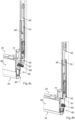
- einen Abschnitt der Treibstange und einen Abschnitt der Türbodendichtung der Türanordnung aus
Figur 1 bei unbetätigter Verriegelungseinrichtung und abgesenktem Dichtelement (Fig.4a ) sowie bei betätigter Verriegelungseinrichtung, zum Stulp hin verlagerter Türbodendichtung und angehobenem Dichtelement (Fig.4b ); und - Fig.5a,b
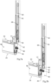
- einen Abschnitt der Treibstange und einen Abschnitt der Türbodendichtung der Türanordnung aus
Figur 1 bei zum Stulp hin verlagerter Türbodendichtung und unbetätiger Verriegelungseinrichtung (Fig.5a ) sowie bei vom Stulp weg verlagerter Türbodendichtung und unbetätigter Verriegelungseinrichtung. -
Figur 1 zeigt eine Türanordnung, die insgesamt mit dem Bezugszeichen 10 bezeichnet ist (nur in einer teilweisen Schnittansicht gezeigt). Die Türanordnung 10 weist einen Türrahmen 12 und einen schwenkbar am Türrahmen 12 gelagerten Türflügel 14 auf. Der Türflügel 14 kann relativ zum Türrahmen 12 zwischen einer Geschlossenstellung und einer Offenstellung verschwenkt werden. Der Türflügel 14 ist an einer Bandseite 16 mittels Türbändern (nicht gezeigt) schwenkbar am Türrahmen 12 gelagert. - Der Türflügel 14 weist eine Verriegelungseinrichtung 20 zur Verriegelung des Türflügels 14 in Geschlossenstellung am Türrahmen 12 auf. Die Verriegelungseinrichtung 20 ist an einer Bandgegenseite 22 des Türflügels 14 angeordnet.
- Der Türflügel 14 weist außerdem eine Türbodendichtung 24 mit einem verlagerbaren Dichtelement 26 zur Abdichtung eines Spalts 28 an der Türflügelunterseite 30 zum Boden 32 hin auf. Wenngleich eine "stumpfe" Montage der Türbodendichtung 24 an der Türflügelunterseite 30 möglich ist, ist die Türbodendichtung 24 im Beispiel in einer an der Türflügelunterseite 30 ausgebildeten Nut 31 angeordnet.
- Das Dichtelement 26 der Türbodendichtung 24 ist mittels einer Antriebsmechanik 34 relativ zur Türflügelunterseite 30 zwischen einer angehobenen Stellung (Türflügelschwenkstellung; vgl.
Fig. 4b ) und einer abgesenkten Stellung (Abdichtstellung; vgl.Fig.1 oderFig.4a ) verlagerbar. - Die Verriegelungseinrichtung 20 weist eine Treibstange 36 auf und ist über die Treibstange 36 derart mit der Türbodendichtung 24 gekoppelt, dass bei einem Entriegeln der Verriegelungseinrichtung 20 in Geschlossenstellung des Türflügels 14 das Dichtelement 26 vor einem Verschwenken des Türflügels 14 aus der abgesenkten Stellung angehoben wird (vgl.
Fig.4a und 4b ). - Die Türbodendichtung 24 ist verschieblich an der Türflügelunterseite 30 befestigt, so dass die Türbodendichtung 24 entlang der Längsrichtung 38 der Türflügelunterseite 30 verschoben werden kann. Die Antriebsmechanik 34 ist vorgespannt, so dass das Dichtelement 26 in die angehobene Stellung gezwungen wird. An dem von der Treibstange 36 abgewandten Ende der Türbodendichtung 24 (Bandseite 16) steht stirnseitig ein Stößel 40 zumindest teilweise aus der Türbodendichtung 24 hervor, wobei der Stößel 40 beim Verschwenken des Türflügels 14 in die Geschlossenstellung am Türrahmen 12 zur Anlage gelangt und durch diesen mit einer Kraft beaufschlagt wird. Dadurch wirkt der Stößel 40 derart auf die Antriebsmechanik 34 ein, dass das Dichtelement 26 in die abgesenkte Stellung verlagert wird und die Türbodendichtung 24 in Richtung der Treibstange 36 (d.h. zur Bandgegenseite 22 hin) vorgespannt wird. Optional kann zwischen Stößel und Antriebsmechanik 34, insbesondere einem als Loslager ausgebildeten Lagerelement 52, eine Dämpfungseinrichtung zur Absenkverzögerung geschaltet sein, wie oben beschrieben.
- Am freien, der Türbodendichtung 24 zugewandten Ende der Treibstange 36 ist ein Distanzstück 42 befestigt, welches in Geschlossenstellung des Türflügels 14 in einem Freiraum 44 zwischen einem Schlossstulp 46 der Verriegelungseinrichtung 20 und dem der Treibstange 36 zugewandten Ende der Türbodendichtung 24 (Bandgegenseite 22) angeordnet ist (vgl.
Fig.1 und4a ). Die Treibstange 36 ist derart mit der Verriegelungseinrichtung 20 gekoppelt, dass beim Entriegeln der Verriegelungseinrichtung 20 (Treibstange 36 wird eingezogen bzw. angehoben) das Distanzstück 42 aus dem Freiraum 44 herausgezogen wird, so dass infolge der Vorspannung der Türbodendichtung 24 zur Treibstange 36 hin die Türbodendichtung 24 zum Schlossstulp 46 hin verlagert wird, wobei das Dichtelement 26 aus der abgesenkten Stellung angehoben wird (vgl.Fig.4b ). - Die Antriebsmechanik 34 weist zwei mit der Türbodendichtung 24 gekoppelte Lagerelemente 50, 52 auf, an denen jeweils eine Koppelstange 54, 56 schwenkbar gelagert und mittels einer Feder 58, 60, im Beispiel einer Zugfeder, relativ zu dem Lagerelement 50, 52 hin vorgespannt ist, wobei die Koppelstangen 54, 56 am freien Ende (vom Lagerelement 50, 52 abgewandtes Ende) jeweils schwenkbar mit dem Dichtelement 26 gekoppelt sind (vgl.
Fig.1 ). - Das Lagerelement 50 ist in einem der Treibstange 36 zugewandten Abschnitt der Türbodendichtung 24 angeordnet und als Festlager ausgeführt. Das Lagerelement 50 ist relativ zur Türbodendichtung 24 entlang deren Längsrichtung 38 unverschieblich und mit einem Befestigungselement 62, im Beispiel mit einer Schraube, relativ zur Türbodendichtung 24 befestigt. Das andere Lagerelement 52 ist in einem von der Treibstange 36 abgewandten Abschnitt der Türbodendichtung 24 angeordnet und als Loslager darin verschieblich geführt, wobei das Loslager durch Beaufschlagung mit dem Stößel 40 entlang der Längsrichtung 38 der Türbodendichtung 24 verschoben werden kann. Das Loslager kann in einem entsprechenden Profilabschnitt des Gehäuses der Türbodendichtung 24, bspw. einem Trägerprofil 84, verschieblich geführt sein.
- Alternativ zur hier beschriebenen Ausgestaltung der Antriebsmechanik 34 kann diese eine Blattfedereinrichtung aufweisen, wie oben beschrieben.
- Die Treibstange 36 weist einen ersten Abschnitt 64 auf, der mit der Verriegelungseinrichtung 20 (bspw. einem Hauptschloss der Verriegelungseinrichtung) gekoppelt ist, und einen separaten zweiten Abschnitt 66, an dem das Distanzstück 42 befestigt ist (vgl.
Fig.3 ). Der erste Abschnitt 64 und der zweite Abschnitt 66 weisen jeweils einen Hintergriffsabschnitt 68, 70 auf, über den sich der erste Abschnitt 64 und der zweite Abschnitt 66 hintergreifen, wobei sich an den Hintergriffsabschnitt 68, 70 jeweils ein Freilaufabschnitt 72, 74 anschließt, so dass der erste Abschnitt 64 und der zweite Abschnitt 66 der Treibstange 36 relativ zueinander verschieblich sind. Somit können die beiden Abschnitte 64, 66 ausgehend von der Stellung, in der die Hintergriffsabschnitte 68, 70 (bspw. bei Belastung auf "Zug") formschlüssig aneinander anliegen (maximale Länge der Treibstange 36), über ein gewisses Maß (Länge des Freilaufabschnitts 72, 74) hinweg relativ zueinander eingeschoben werden (Treibstange 36 verkürzt sich). - Es ist eine Druckfeder 76 vorgesehen, welche einends unmittelbar oder mittelbar am Türflügel 14 oder am Schlossstulp 46 anliegt und andernends am zweiten Abschnitt 66 der Treibstange 36 oder am Distanzstück 42 anliegt (vgl.
Fig.1 und3 ). Durch die Druckfeder 76 ist der zweite Abschnitt 66 der Treibstange 36 relativ zum Türflügel 14 bzw. zum ersten Abschnitt 64 (in Ausfahrrichtung) vorgespannt. Die Druckfeder 76 ist im Beispiel in einer entsprechenden Aufnahme 77 angeordnet, die mittels einer Schraube 78 am Stulp 46 befestigt ist. - Im Beispiel ist zudem eine weitere Druckfeder 80 vorgesehen, welche einends an dem Schlossstulp 46 und andernends an einem dem Schlossstulp 46 zugewandten Ende der Türbodendichtung 24 anliegt (vgl.
Fig.1 und2 ). Dadurch kann eine Rückstellung der Türbodendichtung 24 durch Verlagerung von der Treibstange 36 bzw. dem Schlossstulp 46 weg (zur Bandgegenseite 22 hin) erfolgen, nachdem das Distanzstück 42 aus dem Freiraum 44 weg bewegt und die Türbodendichtung 24 zur Treibstange 36 bzw. dem Schlossstulp 46 hin bewegt wurde (vgl.Fig.5b ). Die weitere Druckfeder 80 dient somit als Rückstellfeder. Die Druckfeder 80 ist im Beispiel mittels einem Haltekörper bzw. Freigabekörper 82 an der Türbodendichtung 24 gehalten (vgl.Fig.1 und2 ). - Zur verschieblichen Befestigung der Türbodendichtung 24 an der Türflügelunterseite 30 weist die Türbodendichtung 24 ein Trägerprofil 84 auf, welches angrenzend an die dem Türflügel 14 (im montierten Zustand) zugewandten Profilseite 85 an zwei Profillängsseiten 86, 87 jeweils eine sich längs erstreckende Nut 88, 89 (im Beispiel eine C-Nut) aufweist (vgl.
Fig.2 ). Es sind ein oder mehrere mittels Befestigungselementen 90 (bspw. Schrauben) an der Türflügelunterseite 30 befestigte Führungsteile 91 vorgesehen, die jeweils in die Nut 88, 89 an den Profillängsseiten 86, 87 eingreifen. - Die Türbodendichtung 24 ist an dem von der Treibstange 36 abgewandten Ende des Türflügels 14 (Bandseite 16) mittels eines Befestigungswinkels 92 befestigt, der eine Verschiebung der Türbodendichtung 24 von der Treibstange 36 weg (bzw. zur Bandseite 16 hin) begrenzt (vgl.
Fig.1 und2 ). Der Befestigungswinkel 92 dient somit als Verschiebeanschlag. Ein erster Schenkel des Befestigungswinkels 92 erstreckt sich entlang der Stirnseite 15 des Türflügels 14. Ein zweiter Schenkel des Befestigungswinkels 92 erstreckt sich an der Türflügelunterseite entlang der Türbodendichtung 24 oder greift in Türbodendichtung 24 ein. Der Befestigungswinkel 92 ist am Türflügel 14 befestigt, im Beispiel durch eine Schraube 95. - Das Dichtelement 26 weist einen Dichtungskörper 27 und eine daran befestigte Dichtlippe 29 auf (vgl.
Fig.2 ). Der Dichtungskörper 27 kann als Strangpressprofil ausgebildet sein, bspw. aus Leichtmetall. Der Dichtungskörper 27 kann eine Aufnahme für die Dichtlippe 29 aufweisen (nicht im Einzelnen gezeigt), an oder in der die Dichtlippe 29 befestigt werden kann. Die Dichtlippe 29 kann aus Kunststoff oder Gummi ausgebildet sein. - Die Verriegelungseinrichtung 20 kann ein Hauptschloss aufweisen (nicht gezeigt), welches über einen Türdrücker und/oder einen Schließzylinder betätigbar ist und, insbesondere über eine Schlossmechanik, mit der Treibstange 36 gekoppelt ist, so dass die Treibstange 36 bei Betätigung des Hauptschlosses antreibbar ist bzw. angetrieben werden kann. Das Hauptschloss kann als Schließelemente eine Schlossfalle und/oder einen Schlossriegel aufweisen (nicht gezeigt).
- Die Verriegelungseinrichtung 20 kann ein oder mehrere Nebenschlösser aufweisen, welche mit der Treibstange 36 gekoppelt sind. In
Figur 3 ist ein Nebenschloss 23 gezeigt, welches als Schließelement einen Fallenriegel 25 aufweist. Das Nebenschloss 23 ist mit dem Hauptschloss gekoppelt, so das Nebenschloss 23 mittels des Hauptschlosses (nicht gezeigt), insbesondere zum Entriegeln der Verriegelungseinrichtung 20, betätigbar ist. - Die Funktionsweise der Vorrichtung wird unter Bezugnahme auf die
Fig.4a bis Fig.5b näher erläutert. - In der in
Figur 4a gezeigten Stellung, die der inFigur 1 gezeigten Stellung entspricht, befindet sich der Türflügel 14 in Geschlossenstellung und die Verriegelungseinrichtung 20 ist verriegelt. Das Dichtelement 26 der Türbodendichtung 24 befindet sich in der abgesenkten Stellung. Durch Einwirken des Stößels 40 auf die Antriebsmechanik 34 ist die Türbodendichtung 24 zur Treibstange 36 bzw. zur Bandgegenseite 22 hin vorgespannt. Das Distanzstück 42 befindet sich im Freiraum 44 zwischen Schlossstulp 46 und dem dem Schlossstulp 46 bzw. dem der Treibstange 36 zugewandten Ende der Türbodendichtung 24. - Wird die Verriegelungseinrichtung 20 in Geschlossenstellung des Türflügels 14 entriegelt, bspw. durch Betätigen eines Türdrückers des Hauptschlosses, wird die Treibstange 36 durch die Verriegelungseinrichtung 20 eingezogen bzw. angehoben, wobei die Hintergriffsabschnitte 68, 70 einander hintergreifen und die Abschnitte 64, 66 der Treibstange angehoben werden. Dadurch wird das Distanzstück 42 aus dem Freiraum 44 herausgezogen (vgl.
Fig.4b ). Da die Türbodendichtung 24 unter Vorspannung steht, wird diese zur Treibstange 36 bzw. zum Schlossstulp 46 hin verlagert, wobei die Druckfeder bzw. Rückstellfeder 80 komprimiert wird (Vorspannkraft größer als Federkraft der Rückstellfeder 80). Das Dichtelement 26 wird durch die Schlossmechanik 34 angehoben. Der Türflügel 14 befindet sich noch in Geschlossenstellung und kann geöffnet bzw. verschwenkt werden, sobald die Schließelemente der Verriegelungseinrichtung 20 in Freigabestellung gelangt sind. - Würde ausgehend von der in
Figur 4b gezeigten Stellung der Türflügel 14 nicht geöffnet werden, sondern die Verriegelungseinrichtung 20 (ohne Öffnung des Türflügels 14), bspw. durch Loslassen des Türdrückers (vgl.Fig.5a ), in die verriegelte Stellung gebracht werden, verfährt der Abschnitt 64 der Treibstange 36 relativ zum Abschnitt 66 der Treibstange 36, indem sich die Hintergriffsabschnitte 68, 70 entlang der Freilaufabschnitte 72, 74 relativ zueinander bewegen. Das Distanzstück 42 kann nicht in den Freiraum 44 eindringen, da der Stößel 40 am Türrahmen 12 anliegt und noch immer auf die Antriebsmechanik 34 einwirkt, so dass sich eine Vorspannung bzw. eine Vorspannkraft ergibt, die die Kraft der Druckfeder bzw. Rückstellfeder 80 übersteigt. Das Distanzstück 42 kann somit nicht in den Freiraum 44 eindringen. Das Dichtelement 26 befindet sich in der angehobenen Stellung. -
Figur 5b zeigt einen Zustand, in dem der Türflügel 14 im Nachgang zu einem Entriegeln der Verriegelungseinrichtung 20, wodurch die Türbodendichtung 24 zur Treibstange 36 bzw. zum Schlossstulp 46 hin verlagert und das Dichtelement 26 angehoben wurde (inFigur 4b dargestellte Situation), geöffnet bzw. verschwenkt wurde (Offenstellung des Türflügels 14). Beim Verschwenken des Türflügels 14 in die Offenstellung wird der Stößel 40 entlastet und gelangt, je nach Türöffnungswinkel, außer Kontakt mit dem Türrahmen 12. Die durch den Stößel 40 auf die Antriebsmechanik 34 aufgebrachte Vorspannung bzw. Vorspannkraft reduziert sich somit, ggf. erfolgt sogar eine Reduzierung auf 0. Dadurch überwiegt die Kraft der Druckfeder bzw. Rückstellfeder 80, durch welche die Türbodendichtung 24 insgesamt von der Treibstange 36 weg bzw. zur Bandseite 16 hin verschoben wird. Dadurch kann das Distanzstück 42 in den Freiraum 44 eindringen. Das Dichtelement 26 befindet sich in der angehobenen Stellung.
Claims (14)
- Türanordnung (10), mit einem Türrahmen (12) und einem schwenkbar am Türrahmen (12) gelagerten und zwischen einer Geschlossenstellung und einer Offenstellung relativ zum Türrahmen (12) verschwenkbaren Türflügel (14), wobei der Türflügel (14) eine Verriegelungseinrichtung (20) zur Verriegelung des Türflügels (14) am Türrahmen (12) und eine Türbodendichtung (24) mit einem verlagerbaren Dichtelement (26) zur Abdichtung eines Spalts (28) an der Türflügelunterseite (30) zum Boden (32) hin aufweist, wobei das Dichtelement (26) mittels einer Antriebsmechanik (34) relativ zur Türflügelunterseite (30) zwischen einer angehobenen Stellung und einer abgesenkten Stellung verlagerbar ist,wobei die Verriegelungseinrichtung (20) eine Treibstange (36) aufweist und die Verriegelungseinrichtung (20) über die Treibstange (36) derart mit der Türbodendichtung (24) gekoppelt ist, dass bei einem Entriegeln der Verriegelungseinrichtung (20) in Geschlossenstellung des Türflügels (14) das Dichtelement (26) vor einem Verschwenken des Türflügels (14) aus der abgesenkten Stellung angehoben wird, wobei die Antriebsmechanik (34) derart vorgespannt ist, dass das Dichtelement (26) in die angehobene Stellung gezwungen wird,dadurch gekennzeichnet, dassdie Türbodendichtung (24) verschieblich an der Türflügelunterseite (30) befestigt ist, so dass die Türbodendichtung (24) entlang der Längsrichtung (38) der Türflügelunterseite (30) verschoben werden kann, wobei an dem von der Treibstange (36) abgewandten Ende der Türbodendichtung (24) stirnseitig ein Stößel (40) zumindest teilweise hervorsteht, wobei der Stößel (40) beim Verschwenken des Türflügels (14) in die Geschlossenstellung am Türrahmen (12) zur Anlage gelangt und durch diesen mit einer Kraft beaufschlagt wird, wodurch der Stößel (40) derart auf die Antriebsmechanik (34) einwirkt, dass das Dichtelement (26) in die abgesenkte Stellung verlagert wird und die Türbodendichtung (24) in Richtung der Treibstange (36) vorgespannt wird.
- Türanordnung (10) nach Anspruch 1, dadurch gekennzeichnet, dass am freien, der Türbodendichtung (24) zugewandten Ende der Treibstange (36) ein Distanzstück (42) befestigt ist, welches in Geschlossenstellung des Türflügels (14) in einem Freiraum (44) zwischen einem Schlossstulp (46) der Verriegelungseinrichtung (20) und dem der Treibstange (36) zugewandten Ende der Türbodendichtung (24) angeordnet ist, wobei die Treibstange (36) derart mit der Verriegelungseinrichtung (20) gekoppelt ist, dass beim Entriegeln der Verriegelungseinrichtung (20) das Distanzstück (42) aus dem Freiraum (44) herausgezogen wird, so dass infolge der Vorspannung der Türbodendichtung (24) zur Treibstange (36) hin die Türbodendichtung (24) zum Schlossstulp (46) hin verlagert wird, wobei das Dichtelement (24) aus der abgesenkten Stellung angehoben wird.
- Türanordnung (10) nach einem der voranstehenden Ansprüche, dadurch gekennzeichnet, dass die Antriebsmechanik (34) zwei mit der Türbodendichtung (24) gekoppelte Lagerelemente (50, 52) aufweist, an denen jeweils eine Koppelstange (54, 56) schwenkbar gelagert und mittels einer Feder (58, 60) relativ zu dem Lagerelement (50, 52) hin vorgespannt ist, wobei die Koppelstangen (54, 56) am freien Ende jeweils schwenkbar mit dem Dichtelement (26) gekoppelt sind.
- Türanordnung (10) nach Anspruch 3, dadurch gekennzeichnet, dass eines der Lagerelemente (50) in einem der Treibstange (36) zugewandten Abschnitt der Türbodendichtung (24) angeordnet und als Festlager ausgeführt ist und dass das andere Lagerelement (52) in einem von der Treibstange (36) abgewandten Abschnitt der Türbodendichtung (24) angeordnet und als Loslager darin verschieblich geführt ist, wobei das Loslager durch Beaufschlagung mit dem Stößel (40) entlang der Längsrichtung (38) der Türbodendichtung (24) verschoben werden kann.
- Türanordnung (10) nach Anspruch 1 oder 2, dadurch gekennzeichnet, dass die Antriebsmechanik (34) eine Federeinrichtung, insbesondere eine Blattfedereinrichtung, aufweist, wobei die Federeinrichtung einends an einem der Treibstange (36) zugewandten Ende der Türbodendichtung (24) an der Türbodendichtung (24) befestigt ist, andernends mit dem Stößel (40) gekoppelt ist und zwischen ihren beiden Enden mit dem Dichtelement (26) gekoppelt ist.
- Türanordnung (10) nach einem der Ansprüche 2 bis 5, dadurch gekennzeichnet, dass die Treibstange (36) einen ersten Abschnitt (64) aufweist, der mit der Verriegelungseinrichtung (20) gekoppelt ist, und einen separaten zweiten Abschnitt (66) aufweist, an dem das Distanzstück (42) befestigt ist, wobei der erste Abschnitt (64) und der zweite Abschnitt (66) jeweils einen Hintergriffsabschnitt (68, 70) aufweisen, über den sich der erste Abschnitt (64) und der zweite Abschnitt (66) hintergreifen, wobei sich an den Hintergriffsabschnitt (68, 70) jeweils ein Freilaufabschnitt (72, 74) anschließt, so dass der erste Abschnitt (64) und der zweite Abschnitt (66) der Treibstange (36) relativ zueinander verschieblich sind.
- Türanordnung (10) nach einem der Ansprüche 2 bis 6, dadurch gekennzeichnet, dass eine Druckfeder (76) vorgesehen ist, welche einends unmittelbar oder mittelbar am Türflügel (14) oder am Schlossstulp (46) anliegt und andernends am zweiten Abschnitt (66) der Treibstange (36) oder am Distanzstück (42) anliegt.
- Türanordnung (10) nach einem der Ansprüche 2 bis 7, dadurch gekennzeichnet, dass eine weitere Druckfeder (80) vorgesehen ist, welche einends an dem Schlossstulp (46) und andernends an einem dem Schlossstulp (46) zugewandten Ende der Türbodendichtung (24) anliegt.
- Türanordnung (10) nach einem der Ansprüche 1 bis 8, dadurch gekennzeichnet, dass zur verschieblichen Befestigung der Türbodendichtung (24) an der Türflügelunterseite (30) die Türbodendichtung (24) ein Trägerprofil (84) aufweist, welches angrenzend an die dem Türflügel (14) zugewandten Profilseite (85) an zwei Profillängsseiten (86, 87) jeweils eine sich längs erstreckende Nut (88, 89) aufweist, wobei ein oder mehrere mittels Befestigungselementen (90) an der Türflügelunterseite (30) befestigte Führungsteile (91) vorgesehen sind, die jeweils in die Nut (88, 89) an den Profillängsseiten (86, 87) eingreifen.
- Türanordnung (10) nach einem der Ansprüche 1 bis 9, dadurch gekennzeichnet, dass die Türbodendichtung (24) an dem von der Treibstange (36) abgewandten Ende des Türflügels (14) mittels eines Befestigungswinkels (92) befestigt ist, der eine Verschiebung der Türbodendichtung (249 von der Treibstange (36) weg begrenzt.
- Türanordnung (10) nach einem der voranstehenden Ansprüche, dadurch gekennzeichnet, dass das Dichtelement (26) einen Dichtungskörper (27) und eine daran befestigte Dichtlippe (29) aufweist.
- Türanordnung (10) nach einem der voranstehenden Ansprüche, dadurch gekennzeichnet, dass die Verriegelungseinrichtung (20) ein Hauptschloss aufweist, welches über einen Türdrücker und/oder einen Schließzylinder betätigbar ist und mit der Treibstange (36) gekoppelt ist, so dass die Treibstange (36) bei Betätigung des Hauptschlosses antreibbar ist.
- Türanordnung (10) nach Anspruch 12, dadurch gekennzeichnet, dass das Hauptschloss als Schließelemente eine Schlossfalle und/oder einen Schlossriegel aufweist.
- Türanordnung (10) nach einem der voranstehenden Ansprüche, dadurch gekennzeichnet, dass die Verriegelungseinrichtung (20) ein oder mehrere Nebenschlösser (23) aufweist, welche mit der Treibstange (36) gekoppelt sind, wobei die Nebenschlösser (23) jeweils einen Fallenriegel (25) und/oder einen Schwenkriegel aufweisen.
Priority Applications (5)
| Application Number | Priority Date | Filing Date | Title |
|---|---|---|---|
| PL22168852.6T PL4265878T3 (pl) | 2022-04-19 | 2022-04-19 | Zespół drzwi |
| EP22168852.6A EP4265878B1 (de) | 2022-04-19 | 2022-04-19 | Türanordnung |
| SI202230127T SI4265878T1 (sl) | 2022-04-19 | 2022-04-19 | Montaža vrat |
| HRP20250548TT HRP20250548T1 (hr) | 2022-04-19 | 2022-04-19 | Sklop vrata |
| RS20250378A RS66800B1 (sr) | 2022-04-19 | 2022-04-19 | Sklop vrata |
Applications Claiming Priority (1)
| Application Number | Priority Date | Filing Date | Title |
|---|---|---|---|
| EP22168852.6A EP4265878B1 (de) | 2022-04-19 | 2022-04-19 | Türanordnung |
Publications (2)
| Publication Number | Publication Date |
|---|---|
| EP4265878A1 EP4265878A1 (de) | 2023-10-25 |
| EP4265878B1 true EP4265878B1 (de) | 2025-02-19 |
Family
ID=81325744
Family Applications (1)
| Application Number | Title | Priority Date | Filing Date |
|---|---|---|---|
| EP22168852.6A Active EP4265878B1 (de) | 2022-04-19 | 2022-04-19 | Türanordnung |
Country Status (5)
| Country | Link |
|---|---|
| EP (1) | EP4265878B1 (de) |
| HR (1) | HRP20250548T1 (de) |
| PL (1) | PL4265878T3 (de) |
| RS (1) | RS66800B1 (de) |
| SI (1) | SI4265878T1 (de) |
Families Citing this family (1)
| Publication number | Priority date | Publication date | Assignee | Title |
|---|---|---|---|---|
| CN120193733B (zh) * | 2025-05-13 | 2025-12-16 | 步阳集团有限公司 | 一种偏轴门 |
Family Cites Families (7)
| Publication number | Priority date | Publication date | Assignee | Title |
|---|---|---|---|---|
| EP0509961B1 (de) | 1991-04-17 | 1994-12-14 | Planet MJT AG | Dichtungsvorrichtung, insbesondere für Türflügel |
| AUPN527795A0 (en) * | 1995-09-06 | 1995-09-28 | Raven Products Pty. Ltd. | Door dropseal |
| JP3486272B2 (ja) * | 1995-09-11 | 2004-01-13 | 株式会社ゴール | 扉下部の隙間遮蔽装置 |
| DE202007016428U1 (de) * | 2007-11-22 | 2008-02-14 | F. Athmer Ohg | Dichtung mit einer absenkbaren Dichtungsleiste und mindestens einem Auslöseelement |
| CN201802271U (zh) * | 2010-07-08 | 2011-04-20 | 浙江临亚工艺品有限公司 | 一种门底自动密封器 |
| US10167666B2 (en) * | 2016-03-11 | 2019-01-01 | Westhampton Architectural Glass, Inc. | Fenestration member sealing system |
| EP3792441A1 (de) * | 2019-09-16 | 2021-03-17 | ASSA ABLOY (Schweiz) AG | Einbruchschutzvorrichtung für eine tür |
-
2022
- 2022-04-19 HR HRP20250548TT patent/HRP20250548T1/hr unknown
- 2022-04-19 RS RS20250378A patent/RS66800B1/sr unknown
- 2022-04-19 EP EP22168852.6A patent/EP4265878B1/de active Active
- 2022-04-19 SI SI202230127T patent/SI4265878T1/sl unknown
- 2022-04-19 PL PL22168852.6T patent/PL4265878T3/pl unknown
Also Published As
| Publication number | Publication date |
|---|---|
| SI4265878T1 (sl) | 2025-06-30 |
| RS66800B1 (sr) | 2025-06-30 |
| PL4265878T3 (pl) | 2025-06-09 |
| HRP20250548T1 (hr) | 2025-06-20 |
| EP4265878A1 (de) | 2023-10-25 |
Similar Documents
| Publication | Publication Date | Title |
|---|---|---|
| EP2474698B1 (de) | Dichtungsvorrichtung mit einem Dichtungsprofil und einem Mechanismus zum Verschieben des Dichtungsprofils bei Betätigung des Mechanismus | |
| EP3071767B1 (de) | Kantriegel und türdichtungssystem | |
| DE102017117573B4 (de) | Anordnung einer Dichtungsvorrichtung sowie damit versehene Schiebetür | |
| EP2063060A2 (de) | Dichtung mit einer absenkbaren Dichtungsleiste und mindestens einem Auslöseelement | |
| EP3417134B1 (de) | Beschlaganordnung zur anbindung eines schieb- und kippbaren flügels | |
| DE202012002741U1 (de) | Beschlag für einen zumindest annähernd parallel abstellbaren und in dieser Parallelabstelllage horizontal verschiebbaren Flügel von Fenstern oder Türen | |
| EP3550102A2 (de) | Baugruppe einer gebäudetür mit einer dichteinheit und einer verriegelulngseinrichtung | |
| EP4265878A1 (de) | Türanordnung | |
| DE3334298C3 (de) | Verschluß für Fenster, Türen oder dergleichen | |
| EP3752700A1 (de) | Absenkbare einbruchsicherung | |
| EP4265879B1 (de) | Türanordnung | |
| DE202022104653U1 (de) | Verlagerungsvorrichtung zur zwangsweisen Verlagerung eines Flügels, insbesondere eines Schiebeflügels, eines Fensters oder einer Tür | |
| DE202013100103U1 (de) | Kippbeschlag für einen Fenster- oder Türflügel | |
| EP3199740B1 (de) | Dichtungsvorrichtung mit bewegbarer dichtleiste | |
| EP3085876B1 (de) | Absenkdichtungsvorrichtung | |
| EP4390026B1 (de) | Beschlaganordnung für einen hebe-schiebeflügel | |
| EP3348756B1 (de) | Schliessvorrichtung für eine tür, ein fenster oder dergleichen | |
| DE10133938A1 (de) | Türfeststeller für Schiebetüren von Kraftfahrzeugen | |
| DE102012106191B4 (de) | Vorspannbauteil für eine Fenster- oder Türvorrichtung und Fenster- oder Türvorrichtung | |
| EP3783176B1 (de) | Treibstangenbeschlag, tür- oder fensterverschluss und tür- oder fensteranordnung | |
| EP2682556B1 (de) | Dichtungsanordnung für eine Tür oder ein Fenster | |
| DE102023122564A1 (de) | Gegenkasten für einen Standflügelverschluss | |
| EP4606978A1 (de) | Schliessvorrichtung | |
| EP1780359A2 (de) | Flügelheber für einen Treibstangenbeschlag | |
| DE202022104652U1 (de) | Verlagerungsvorrichtung zur zwangsweisen Verlagerung eines Flügels, insbesondere eines Schiebeflügels, eines Fensters oder einer Tür |
Legal Events
| Date | Code | Title | Description |
|---|---|---|---|
| REG | Reference to a national code |
Ref country code: HR Ref legal event code: TUEP Ref document number: P20250548T Country of ref document: HR |
|
| STAA | Information on the status of an ep patent application or granted ep patent |
Free format text: STATUS: REQUEST FOR EXAMINATION WAS MADE |
|
| PUAI | Public reference made under article 153(3) epc to a published international application that has entered the european phase |
Free format text: ORIGINAL CODE: 0009012 |
|
| 17P | Request for examination filed |
Effective date: 20230522 |
|
| AK | Designated contracting states |
Kind code of ref document: A1 Designated state(s): AL AT BE BG CH CY CZ DE DK EE ES FI FR GB GR HR HU IE IS IT LI LT LU LV MC MK MT NL NO PL PT RO RS SE SI SK SM TR |
|
| GRAP | Despatch of communication of intention to grant a patent |
Free format text: ORIGINAL CODE: EPIDOSNIGR1 |
|
| STAA | Information on the status of an ep patent application or granted ep patent |
Free format text: STATUS: GRANT OF PATENT IS INTENDED |
|
| INTG | Intention to grant announced |
Effective date: 20241022 |
|
| GRAS | Grant fee paid |
Free format text: ORIGINAL CODE: EPIDOSNIGR3 |
|
| GRAA | (expected) grant |
Free format text: ORIGINAL CODE: 0009210 |
|
| STAA | Information on the status of an ep patent application or granted ep patent |
Free format text: STATUS: THE PATENT HAS BEEN GRANTED |
|
| AK | Designated contracting states |
Kind code of ref document: B1 Designated state(s): AL AT BE BG CH CY CZ DE DK EE ES FI FR GB GR HR HU IE IS IT LI LT LU LV MC MK MT NL NO PL PT RO RS SE SI SK SM TR |
|
| REG | Reference to a national code |
Ref country code: GB Ref legal event code: FG4D Free format text: NOT ENGLISH |
|
| REG | Reference to a national code |
Ref country code: CH Ref legal event code: EP |
|
| REG | Reference to a national code |
Ref country code: IE Ref legal event code: FG4D Free format text: LANGUAGE OF EP DOCUMENT: GERMAN |
|
| REG | Reference to a national code |
Ref country code: DE Ref legal event code: R096 Ref document number: 502022002911 Country of ref document: DE |
|
| P01 | Opt-out of the competence of the unified patent court (upc) registered |
Free format text: CASE NUMBER: APP_6682/2025 Effective date: 20250210 |
|
| REG | Reference to a national code |
Ref country code: NL Ref legal event code: FP |
|
| REG | Reference to a national code |
Ref country code: HR Ref legal event code: ODRP Ref document number: P20250548T Country of ref document: HR Payment date: 20250508 Year of fee payment: 4 |
|
| REG | Reference to a national code |
Ref country code: HR Ref legal event code: T1PR Ref document number: P20250548 Country of ref document: HR |
|
| PG25 | Lapsed in a contracting state [announced via postgrant information from national office to epo] |
Ref country code: FI Free format text: LAPSE BECAUSE OF FAILURE TO SUBMIT A TRANSLATION OF THE DESCRIPTION OR TO PAY THE FEE WITHIN THE PRESCRIBED TIME-LIMIT Effective date: 20250219 |
|
| PG25 | Lapsed in a contracting state [announced via postgrant information from national office to epo] |
Ref country code: ES Free format text: LAPSE BECAUSE OF FAILURE TO SUBMIT A TRANSLATION OF THE DESCRIPTION OR TO PAY THE FEE WITHIN THE PRESCRIBED TIME-LIMIT Effective date: 20250219 |
|
| REG | Reference to a national code |
Ref country code: LT Ref legal event code: MG9D |
|
| PG25 | Lapsed in a contracting state [announced via postgrant information from national office to epo] |
Ref country code: IS Free format text: LAPSE BECAUSE OF FAILURE TO SUBMIT A TRANSLATION OF THE DESCRIPTION OR TO PAY THE FEE WITHIN THE PRESCRIBED TIME-LIMIT Effective date: 20250619 Ref country code: NO Free format text: LAPSE BECAUSE OF FAILURE TO SUBMIT A TRANSLATION OF THE DESCRIPTION OR TO PAY THE FEE WITHIN THE PRESCRIBED TIME-LIMIT Effective date: 20250519 |
|
| PG25 | Lapsed in a contracting state [announced via postgrant information from national office to epo] |
Ref country code: PT Free format text: LAPSE BECAUSE OF FAILURE TO SUBMIT A TRANSLATION OF THE DESCRIPTION OR TO PAY THE FEE WITHIN THE PRESCRIBED TIME-LIMIT Effective date: 20250620 Ref country code: LV Free format text: LAPSE BECAUSE OF FAILURE TO SUBMIT A TRANSLATION OF THE DESCRIPTION OR TO PAY THE FEE WITHIN THE PRESCRIBED TIME-LIMIT Effective date: 20250219 |
|
| PG25 | Lapsed in a contracting state [announced via postgrant information from national office to epo] |
Ref country code: GR Free format text: LAPSE BECAUSE OF FAILURE TO SUBMIT A TRANSLATION OF THE DESCRIPTION OR TO PAY THE FEE WITHIN THE PRESCRIBED TIME-LIMIT Effective date: 20250520 Ref country code: BG Free format text: LAPSE BECAUSE OF FAILURE TO SUBMIT A TRANSLATION OF THE DESCRIPTION OR TO PAY THE FEE WITHIN THE PRESCRIBED TIME-LIMIT Effective date: 20250219 |
|
| PG25 | Lapsed in a contracting state [announced via postgrant information from national office to epo] |
Ref country code: SE Free format text: LAPSE BECAUSE OF FAILURE TO SUBMIT A TRANSLATION OF THE DESCRIPTION OR TO PAY THE FEE WITHIN THE PRESCRIBED TIME-LIMIT Effective date: 20250219 |
|
| PG25 | Lapsed in a contracting state [announced via postgrant information from national office to epo] |
Ref country code: SM Free format text: LAPSE BECAUSE OF FAILURE TO SUBMIT A TRANSLATION OF THE DESCRIPTION OR TO PAY THE FEE WITHIN THE PRESCRIBED TIME-LIMIT Effective date: 20250219 |
|
| PG25 | Lapsed in a contracting state [announced via postgrant information from national office to epo] |
Ref country code: DK Free format text: LAPSE BECAUSE OF FAILURE TO SUBMIT A TRANSLATION OF THE DESCRIPTION OR TO PAY THE FEE WITHIN THE PRESCRIBED TIME-LIMIT Effective date: 20250219 |
|
| PG25 | Lapsed in a contracting state [announced via postgrant information from national office to epo] |
Ref country code: EE Free format text: LAPSE BECAUSE OF FAILURE TO SUBMIT A TRANSLATION OF THE DESCRIPTION OR TO PAY THE FEE WITHIN THE PRESCRIBED TIME-LIMIT Effective date: 20250219 Ref country code: CZ Free format text: LAPSE BECAUSE OF FAILURE TO SUBMIT A TRANSLATION OF THE DESCRIPTION OR TO PAY THE FEE WITHIN THE PRESCRIBED TIME-LIMIT Effective date: 20250219 |
|
| PG25 | Lapsed in a contracting state [announced via postgrant information from national office to epo] |
Ref country code: RO Free format text: LAPSE BECAUSE OF FAILURE TO SUBMIT A TRANSLATION OF THE DESCRIPTION OR TO PAY THE FEE WITHIN THE PRESCRIBED TIME-LIMIT Effective date: 20250219 |
|
| PG25 | Lapsed in a contracting state [announced via postgrant information from national office to epo] |
Ref country code: SK Free format text: LAPSE BECAUSE OF FAILURE TO SUBMIT A TRANSLATION OF THE DESCRIPTION OR TO PAY THE FEE WITHIN THE PRESCRIBED TIME-LIMIT Effective date: 20250219 |
|
| REG | Reference to a national code |
Ref country code: DE Ref legal event code: R097 Ref document number: 502022002911 Country of ref document: DE |
|
| PG25 | Lapsed in a contracting state [announced via postgrant information from national office to epo] |
Ref country code: LU Free format text: LAPSE BECAUSE OF NON-PAYMENT OF DUE FEES Effective date: 20250419 |
|
| PG25 | Lapsed in a contracting state [announced via postgrant information from national office to epo] |
Ref country code: MC Free format text: LAPSE BECAUSE OF FAILURE TO SUBMIT A TRANSLATION OF THE DESCRIPTION OR TO PAY THE FEE WITHIN THE PRESCRIBED TIME-LIMIT Effective date: 20250219 |
|
| PLBE | No opposition filed within time limit |
Free format text: ORIGINAL CODE: 0009261 |
|
| STAA | Information on the status of an ep patent application or granted ep patent |
Free format text: STATUS: NO OPPOSITION FILED WITHIN TIME LIMIT |
|
| REG | Reference to a national code |
Ref country code: CH Ref legal event code: L10 Free format text: ST27 STATUS EVENT CODE: U-0-0-L10-L00 (AS PROVIDED BY THE NATIONAL OFFICE) Effective date: 20251231 |
|
| REG | Reference to a national code |
Ref country code: DE Ref legal event code: R082 Ref document number: 502022002911 Country of ref document: DE |
|
| 26N | No opposition filed |
Effective date: 20251120 |
|
| PG25 | Lapsed in a contracting state [announced via postgrant information from national office to epo] |
Ref country code: IE Free format text: LAPSE BECAUSE OF NON-PAYMENT OF DUE FEES Effective date: 20250419 |
|
| REG | Reference to a national code |
Ref country code: CH Ref legal event code: U11 Free format text: ST27 STATUS EVENT CODE: U-0-0-U10-U11 (AS PROVIDED BY THE NATIONAL OFFICE) Effective date: 20260501 |
|
| REG | Reference to a national code |
Ref country code: HR Ref legal event code: ODRP Ref document number: P20250548 Country of ref document: HR Payment date: 20260409 Year of fee payment: 5 |
|
| PGFP | Annual fee paid to national office [announced via postgrant information from national office to epo] |
Ref country code: NL Payment date: 20260420 Year of fee payment: 5 |
|
| PG25 | Lapsed in a contracting state [announced via postgrant information from national office to epo] |
Ref country code: CY Free format text: LAPSE BECAUSE OF FAILURE TO SUBMIT A TRANSLATION OF THE DESCRIPTION OR TO PAY THE FEE WITHIN THE PRESCRIBED TIME-LIMIT Effective date: 20250219 |
|
| PG25 | Lapsed in a contracting state [announced via postgrant information from national office to epo] |
Ref country code: LT Free format text: LAPSE BECAUSE OF FAILURE TO SUBMIT A TRANSLATION OF THE DESCRIPTION OR TO PAY THE FEE WITHIN THE PRESCRIBED TIME-LIMIT Effective date: 20250219 |
|
| PGFP | Annual fee paid to national office [announced via postgrant information from national office to epo] |
Ref country code: RS Payment date: 20260409 Year of fee payment: 5 Ref country code: PL Payment date: 20260414 Year of fee payment: 5 |
|
| PGFP | Annual fee paid to national office [announced via postgrant information from national office to epo] |
Ref country code: IT Payment date: 20260427 Year of fee payment: 5 |
|
| PGFP | Annual fee paid to national office [announced via postgrant information from national office to epo] |
Ref country code: DE Payment date: 20260422 Year of fee payment: 5 |
|
| PGFP | Annual fee paid to national office [announced via postgrant information from national office to epo] |
Ref country code: AT Payment date: 20260714 Year of fee payment: 5 |
|
| PGFP | Annual fee paid to national office [announced via postgrant information from national office to epo] |
Ref country code: CH Payment date: 20260501 Year of fee payment: 5 Ref country code: BE Payment date: 20260420 Year of fee payment: 5 |
|
| PGFP | Annual fee paid to national office [announced via postgrant information from national office to epo] |
Ref country code: HR Payment date: 20260409 Year of fee payment: 5 |
|
| PGFP | Annual fee paid to national office [announced via postgrant information from national office to epo] |
Ref country code: FR Payment date: 20260420 Year of fee payment: 5 |
|
| PGFP | Annual fee paid to national office [announced via postgrant information from national office to epo] |
Ref country code: SI Payment date: 20260409 Year of fee payment: 5 |