EP4265760A1 - Flusskerndraht und schutzgas-lichtbogenschweissverfahren - Google Patents
Flusskerndraht und schutzgas-lichtbogenschweissverfahren Download PDFInfo
- Publication number
- EP4265760A1 EP4265760A1 EP21906193.4A EP21906193A EP4265760A1 EP 4265760 A1 EP4265760 A1 EP 4265760A1 EP 21906193 A EP21906193 A EP 21906193A EP 4265760 A1 EP4265760 A1 EP 4265760A1
- Authority
- EP
- European Patent Office
- Prior art keywords
- mass
- wire
- content
- less
- flux
- Prior art date
- Legal status (The legal status is an assumption and is not a legal conclusion. Google has not performed a legal analysis and makes no representation as to the accuracy of the status listed.)
- Pending
Links
Images
Classifications
-
- C—CHEMISTRY; METALLURGY
- C22—METALLURGY; FERROUS OR NON-FERROUS ALLOYS; TREATMENT OF ALLOYS OR NON-FERROUS METALS
- C22C—ALLOYS
- C22C38/00—Ferrous alloys, e.g. steel alloys
- C22C38/02—Ferrous alloys, e.g. steel alloys containing silicon
-
- B—PERFORMING OPERATIONS; TRANSPORTING
- B23—MACHINE TOOLS; METAL-WORKING NOT OTHERWISE PROVIDED FOR
- B23K—SOLDERING OR UNSOLDERING; WELDING; CLADDING OR PLATING BY SOLDERING OR WELDING; CUTTING BY APPLYING HEAT LOCALLY, e.g. FLAME CUTTING; WORKING BY LASER BEAM
- B23K35/00—Rods, electrodes, materials, or media, for use in soldering, welding, or cutting
- B23K35/02—Rods, electrodes, materials, or media, for use in soldering, welding, or cutting characterised by mechanical features, e.g. shape
- B23K35/0255—Rods, electrodes, materials, or media, for use in soldering, welding, or cutting characterised by mechanical features, e.g. shape for use in welding
- B23K35/0261—Rods, electrodes or wires
- B23K35/0266—Rods, electrodes or wires flux-cored
-
- B—PERFORMING OPERATIONS; TRANSPORTING
- B23—MACHINE TOOLS; METAL-WORKING NOT OTHERWISE PROVIDED FOR
- B23K—SOLDERING OR UNSOLDERING; WELDING; CLADDING OR PLATING BY SOLDERING OR WELDING; CUTTING BY APPLYING HEAT LOCALLY, e.g. FLAME CUTTING; WORKING BY LASER BEAM
- B23K35/00—Rods, electrodes, materials, or media, for use in soldering, welding, or cutting
- B23K35/22—Rods, electrodes, materials, or media, for use in soldering, welding, or cutting characterised by the composition or nature of the material
- B23K35/24—Selection of soldering or welding materials proper
- B23K35/30—Selection of soldering or welding materials proper with the principal constituent melting at less than 1550°C
- B23K35/3053—Fe as the principal constituent
- B23K35/3073—Fe as the principal constituent with Mn as next major constituent
-
- B—PERFORMING OPERATIONS; TRANSPORTING
- B23—MACHINE TOOLS; METAL-WORKING NOT OTHERWISE PROVIDED FOR
- B23K—SOLDERING OR UNSOLDERING; WELDING; CLADDING OR PLATING BY SOLDERING OR WELDING; CUTTING BY APPLYING HEAT LOCALLY, e.g. FLAME CUTTING; WORKING BY LASER BEAM
- B23K35/00—Rods, electrodes, materials, or media, for use in soldering, welding, or cutting
- B23K35/22—Rods, electrodes, materials, or media, for use in soldering, welding, or cutting characterised by the composition or nature of the material
- B23K35/24—Selection of soldering or welding materials proper
- B23K35/30—Selection of soldering or welding materials proper with the principal constituent melting at less than 1550°C
- B23K35/3053—Fe as the principal constituent
- B23K35/3093—Fe as the principal constituent with other elements as next major constituents
-
- B—PERFORMING OPERATIONS; TRANSPORTING
- B23—MACHINE TOOLS; METAL-WORKING NOT OTHERWISE PROVIDED FOR
- B23K—SOLDERING OR UNSOLDERING; WELDING; CLADDING OR PLATING BY SOLDERING OR WELDING; CUTTING BY APPLYING HEAT LOCALLY, e.g. FLAME CUTTING; WORKING BY LASER BEAM
- B23K9/00—Arc welding or cutting
- B23K9/16—Arc welding or cutting making use of shielding gas
- B23K9/173—Arc welding or cutting making use of shielding gas and of a consumable electrode
-
- C—CHEMISTRY; METALLURGY
- C22—METALLURGY; FERROUS OR NON-FERROUS ALLOYS; TREATMENT OF ALLOYS OR NON-FERROUS METALS
- C22C—ALLOYS
- C22C38/00—Ferrous alloys, e.g. steel alloys
- C22C38/002—Ferrous alloys, e.g. steel alloys containing In, Mg, or other elements not provided for in one single group C22C38/001 - C22C38/60
-
- C—CHEMISTRY; METALLURGY
- C22—METALLURGY; FERROUS OR NON-FERROUS ALLOYS; TREATMENT OF ALLOYS OR NON-FERROUS METALS
- C22C—ALLOYS
- C22C38/00—Ferrous alloys, e.g. steel alloys
- C22C38/04—Ferrous alloys, e.g. steel alloys containing manganese
-
- C—CHEMISTRY; METALLURGY
- C22—METALLURGY; FERROUS OR NON-FERROUS ALLOYS; TREATMENT OF ALLOYS OR NON-FERROUS METALS
- C22C—ALLOYS
- C22C38/00—Ferrous alloys, e.g. steel alloys
- C22C38/06—Ferrous alloys, e.g. steel alloys containing aluminium
-
- C—CHEMISTRY; METALLURGY
- C22—METALLURGY; FERROUS OR NON-FERROUS ALLOYS; TREATMENT OF ALLOYS OR NON-FERROUS METALS
- C22C—ALLOYS
- C22C38/00—Ferrous alloys, e.g. steel alloys
- C22C38/08—Ferrous alloys, e.g. steel alloys containing nickel
-
- C—CHEMISTRY; METALLURGY
- C22—METALLURGY; FERROUS OR NON-FERROUS ALLOYS; TREATMENT OF ALLOYS OR NON-FERROUS METALS
- C22C—ALLOYS
- C22C38/00—Ferrous alloys, e.g. steel alloys
- C22C38/12—Ferrous alloys, e.g. steel alloys containing tungsten, tantalum, molybdenum, vanadium, or niobium
-
- C—CHEMISTRY; METALLURGY
- C22—METALLURGY; FERROUS OR NON-FERROUS ALLOYS; TREATMENT OF ALLOYS OR NON-FERROUS METALS
- C22C—ALLOYS
- C22C38/00—Ferrous alloys, e.g. steel alloys
- C22C38/16—Ferrous alloys, e.g. steel alloys containing copper
Definitions
- the present invention relates to a flux-cored wire for gas-shielded arc welding, which is used for welding a steel material with a tensile strength of 620 MPa class, and a gas-shielded arc welding method.
- Offshore structures used for the drilling and production of petroleum, gas, or the like and pipelines used for the transportation of oil, gas, or the like are increasing in size and operation in cold regions, and steel plates and welding materials used in the construction of these welded structures are required to have high strength and low-temperature toughness.
- a post-weld heat treatment may be performed for stress relief after the welding procedure.
- PWHT may reduce the strength and toughness of a weld zone and impair required characteristics.
- a flux-cored wire to which Ni is added is generally used to improve the strength and toughness after PWHT.
- NACE National Association of Corrosion Engineers
- Patent Literature 1 discloses a flux-cored wire for carbon dioxide shielded arc welding, which contains a slag component composed of a metal oxide composed mainly of TiOz and a compound containing Na and K, an optimum alloy component, and a deoxidizer.
- Patent Literature 2 proposes a flux-cored wire for Ar-CO 2 mixed gas shielded arc welding, which contains a slag component composed of a metal oxide composed mainly of TiOz and a fluorine compound containing Na and K, an optimum alloy component, and a deoxidizer.
- Patent Literature 1 and Patent Literature 2 it is possible to produce a weld metal with high welding performance in all-position welding, high cold cracking resistance, high low-temperature toughness, and good crack tip opening displacement (CTOD) characteristics.
- CTOD crack tip opening displacement
- Patent Literature 1 the Ni content ranges from 0.8% to 3.0% by mass, which does not necessarily satisfy the Ni content of a weld metal specified in NACE MR 0175, and the strength and low-temperature toughness after PWHT are not taken into consideration.
- Patent Literature 2 although the Ni content ranges from 0.1% to 0.5% by mass, the strength and low-temperature toughness after PWHT are not taken into consideration.
- the present invention has been made in view of such situations and aims to provide a flux-cored wire that, even having a Ni content of 1% by mass or less, can provide a weld metal with high strength and low-temperature toughness not only as it is welded (hereinafter also referred to as "as-welded") but also after PWHT.
- the object of the present invention is achieved by the following [1] relating to a flux-cored wire.
- the present invention can provide a flux-cored wire that, even having a Ni content of 1% by mass or less, can provide a weld metal with high strength and low-temperature toughness not only as-welded but also after PWHT.
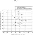
- Fig. 1 is a graph of the relationship between absorbed energy and tensile strength wherein the vertical axis represents Charpy absorbed energy at -40°C after PWHT and the horizontal axis represents the tensile strength after PWHT.
- the present embodiment A mode for carrying out the present invention (hereinafter referred to as "the present embodiment") is described in detail below.
- the present invention is not limited to the embodiments described below and may be modified without departing from the gist of the present invention.
- the term "content”, as used herein, refers to % by mass based on the total mass of a flux-cored wire.
- Each element contained in a flux-cored wire according to the present embodiment may be contained in either a steel sheath or flux or in both the steel sheath and the flux.
- each element may be contained in a flux-cored wire in the form of metal, in the form of a compound, or in the form of both metal and a compound.
- each element contained in any form in a flux-cored wire is defined by a converted value in terms of a single element.
- the Si content refers to the total Si-equivalent value of metal Si and Si compounds.
- the metal Si includes a Si element and Si alloys.
- the flux-cored wire (hereinafter also referred to simply as the "wire") according to the present embodiment is a steel sheath (hereinafter also referred to simply as a "sheath”) filled with flux.
- the outer diameter of the wire is preferably, but not limited to, 0.9 mm or more and 1.6 mm or less, for example.
- the flux filling ratio can be any value, provided that each element content of the wire is within the scope of the present invention. To further improve wire drawability and wire feedability, the flux filling ratio is preferably, for example, 10% by mass or more and 20% by mass or less based on the total mass of the wire.
- the wire may have a sheath with or without a seam, and the seam may have any form and any cross-sectional shape.
- the present inventors have studied the mechanism by which toughness after PWHT is decreased and have also conducted extensive studies to provide a weld metal with high low-temperature toughness. As a result, the present inventors have completed the present invention on the basis of the following findings.
- PWHT causes segregation of an impurity element and precipitation of a carbide at a prior-austenite grain boundary in a weld metal and decreases grain boundary bonding strength. This promotes fracture along the grain boundary, causes temper embrittlement, and decreases the toughness of a weld metal. Furthermore, carbide with a larger size precipitated at the grain boundary by PWHT more significantly decreases the toughness.
- C is a component having the effect of improving the strength of a weld metal.
- a C content of less than 0.026% by mass results in undesired strength.
- the C content based on the total mass of the wire is 0.026 by mass or more, preferably 0.028% by mass or more, more preferably 0.029% by mass or more.
- a C content of more than 0.060% by mass results in promoted coarsening of a grain boundary carbide and lower low-temperature toughness after PWHT.
- the C content based on the total mass of the wire is 0.060% by mass or less, preferably 0.058% by mass or less, more preferably 0.056% by mass or less.
- Si is a component that promotes the formation of a hard martensite-austenite constituent, thereby promoting temper embrittlement by PWHT and reducing the low-temperature toughness.
- a Si content of more than 0.50% by mass results in lower low-temperature toughness after PWHT.
- the Si content based on the total mass of the wire is 0.50% by mass or less, preferably 0.45% by mass or less, more preferably 0.40% by mass or less.
- Si is a component that cannot be completely decreased to 0% by mass and has the effect of reducing a pore defect as a deoxidizing element. Even a trace amount of Si in the wire can have the effect of reducing a pore defect.
- the Si Content based on the total mass of the wire is more than 0% by mass, preferably 0.10% by mass or more, more preferably 0.15% by mass or more.
- Mn is a component having the effect of improving the strength of a weld metal.
- a Mn content of less than 1.3% by mass results in undesired strength.
- the Mn content based on the total mass of the wire is 1.3% by mass or more, preferably 1.5% by mass or more, more preferably 1.7% by mass or more.
- the Mn content based on the total mass of the wire is 2.8% by mass or less.
- the Mn content based on the total mass of the wire is preferably 2.7% by mass or less, more preferably 2.5% by mass or less, to reduce the occurrence of intergranular fracture of a structure mainly composed of an as-casted zone and further improve the low-temperature toughness.
- Cu is a component having the effect of decreasing the size of the structure of a weld metal and improving the low-temperature toughness while maintaining the strength.
- a Cu content of less than 0.20% by mass results in undesired strength and low-temperature toughness.
- the Cu content based on the total mass of the wire is 0.20% by mass or more, preferably 0.30% by mass or more, more preferably 0.40% by mass or more.
- a Cu content of more than 1.50% by mass results in the formation of a precipitate promoted by PWHT and lower toughness.
- the Cu content based on the total mass of the wire is 1.50% by mass or less, preferably 1.35% by mass or less, more preferably 1.20% by mass or less.
- the Cu contained in the plating is also included in the Cu content defined in the present embodiment, that is, in the range of 0.20% by mass or more and 1.50% by mass or less.
- Ni is a component having the effect of improving the low-temperature toughness of a weld metal by strengthening the matrix.
- a Ni content of less than 0.45% by mass results in undesired low-temperature toughness.
- the Ni content based on the total mass of the wire is 0.45% by mass or more, preferably 0.50% by mass or more, more preferably 0.60% by mass or more.
- a Ni content of more than 1.00% by mass results in a weld metal with a Ni content outside the range specified in NACE MR 0175 and increased susceptibility to sulfide stress corrosion cracking in a hydrogen sulfide environment.
- the Ni content based on the total mass of the wire is 1.00% by mass or less.
- Mo is a component that improves the strength and has the effect of reducing temper embrittlement. Fine precipitation of Mo 2 C in a grain of a weld metal can reduce the growth of a carbide precipitated at the grain boundary and reduce the decrease in the low-temperature toughness after PWHT. At a Mo content of less than 0.15% by mass, it is impossible to achieve desired low-temperature toughness after PWHT while maintaining desired strength. Thus, the Mo content based on the total mass of the wire is 0.15% by mass or more, preferably 0.18% by mass or more, more preferably 0.20% by mass or more.
- the Mo content based on the total mass of the wire is 0.65% by mass or less, preferably 0.60% by mass or less, more preferably 0.55% by mass or less.
- Mg is a component that has a deoxidation effect and improves the strength.
- a Mg content of less than 0.30% by mass results in undesired strength.
- the Mg content based on the total mass of the wire is 0.30% by mass or more, preferably 0.33% by mass or more, more preferably 0.36% by mass or more.
- the Mg content based on the total mass of the wire is 0.65% by mass or less, preferably 0.62% by mass or less, more preferably 0.60% by mass or less.
- B is a component that segregates at a prior-austenite grain boundary, suppresses proeutectoid ferrite, and thereby has the effect of improving the toughness of a weld metal.
- a B content of less than 0.001% by mass based on the total mass of the wire results in an insufficient effect of improving the toughness of a weld metal.
- the B content based on the total mass of the wire is 0.001% by mass or more, preferably 0.002% by mass or more.
- a B content of more than 0.010% by mass results in a precipitate excessively formed by PWHT and lower toughness.
- the B content based on the total mass of the wire is 0.010% by mass or less, preferably 0.009% by mass or less.
- Cr is a component that promotes the precipitation and growth of a coarse grain boundary carbide by PWHT and reduces the low-temperature toughness.
- a Cr content of more than 0.10% by mass based on the total mass of the wire results in lower low-temperature toughness after PWHT.
- the Cr content based on the total mass of the wire is 0.10% by mass or less, preferably 0.07% by mass or less, more preferably 0.05% by mass or less.
- Al is a component that prevents nucleation of acicular ferrite when excessively contained in the wire and reduces the toughness regardless of the presence or absence of PWHT.
- An Al content of more than 0.10% by mass results in a weld metal with lower toughness.
- the Al content based on the total mass of the wire is 0.10% by mass or less, preferably 0.09% by mass or less.
- Nb and V are components that precipitate a carbide by PWHT and thereby reduce the low-temperature toughness.
- [Nb] + [V] of more than 0.015 results in lower low-temperature toughness after PWHT, wherein [Nb] denotes the Nb content of the wire expressed in % by mass based on the total mass of the wire and [V] denotes the V content of the wire expressed in % by mass based on the total mass of the wire.
- [Nb] + [V] is 0.015 or less, preferably 0.010 or less.
- the relationships between the Mn content, the Si content, the Cr content, the Nb content, and the V content, and the Cu content, the Ni content, and the Mo content are also important.
- the present inventors have found that appropriately controlling the value obtained by the following formula A while specifying each component content can further improve the low-temperature toughness after PWHT.
- the value obtained using the formula A is preferably 0.55 or more and 0.90 or less, more preferably 0.58 or more and 0.85 or less.
- [Cu] denotes the Cu content expressed in % by mass based on the total mass of the wire.
- Ni denotes the Ni content of the wire expressed in % by mass based on the total mass of the wire.
- Mo denotes the Mo content of the wire expressed in % by mass based on the total mass of the wire.
- [Mn] denotes the Mn content of the wire expressed in % by mass based on the total mass of the wire.
- Si denotes the Si content of the wire expressed in % by mass based on the total mass of the wire.
- [Cr] denotes the Cr content of the wire expressed in % by mass based on the total mass of the wire.
- Nb denotes the Nb content of the wire expressed in % by mass based on the total mass of the wire.
- [V] denotes the V content of the wire expressed in % by mass based on the total mass of the wire.
- Cu is a component having the effect of improving the low-temperature toughness while maintaining the strength of a weld metal after PWHT
- Mo is a component having the effect of improving the strength while maintaining the low-temperature toughness after PWHT.
- the value obtained using the formula B is preferably 0.5 or more and 5.0 or less, more preferably 1.2 or more and 3.5 or less.
- [Cu] denotes the Cu content expressed in % by mass based on the total mass of the wire
- [Mo] denotes the Mo content of the wire expressed in % by mass based on the total mass of the wire.
- the present inventors have focused on the yield of C in a weld metal from the sheath and the flux and have found that the yield of C in the weld metal is lower in C from the sheath than in C from the flux and that this can further improve the low-temperature toughness after PWHT.
- [C] O /[C] B is preferably 0.37 or less, more preferably 0.35 or less.
- the lower limit of [C] O /[C] B is not particularly specified and is preferably 0.10 or more, more preferably 0.13 or more, to increase the hardness of the sheath and improve the wire feedability.
- the total C, Si, Mn, Cu, Ni, Mo, Mg, B, Cr, Al, Nb, and V content is preferably 3.0% by mass or more, more preferably 3.5% by mass or more, to improve welding performance. Furthermore, to improve wire drawability, the total component content is preferably 7.0% by mass or less, more preferably 6.0% by mass or less.
- the wire according to the present embodiment preferably further contains at least one selected from the group consisting of Ti, Zr, F, Na, and K within the following content ranges. The reason for limiting these element contents of the wire is described below.
- Ti is a component that functions as a slag former, facilitates welding in a welding position other than the flat position, for example, in a vertical-up position or an overhead position, and has the effect of providing high welding performance in all positions.
- the Ti content based on the total mass of the wire is preferably 3.3% by mass or more and 6.0% by mass or less, more preferably 3.6% by mass or more and 5.5% by mass or less, to appropriately maintain the amount of slag to be formed and provide high welding performance.
- Zr is a component having the effect of improving bead wetting and forming a flat bead shape.
- the Zr content based on the total mass of the wire is preferably 0.25% by mass or less, more preferably 0.20% by mass or less, to improve bead wetting and form a flat bead shape while maintaining high slag detachability.
- the F is a component having the effect of stabilizing arc.
- the F content based on the total mass of the wire is preferably 0.05% by mass or more and 0.30% by mass or less, more preferably 0.10% by mass or more and 0.25% by mass or less, to reduce the amount of spatter and sufficiently stabilize the arc.
- Total Na and K content 0.10% by mass or more and 0.30% by mass or less>
- Na and K are components having the effect of stabilizing the arc.
- the total Na and K content based on the total mass of the wire is preferably 0.10% by mass or more and 0.30% by mass or less, more preferably 0.12% by mass or more and 0.28% by mass or less, to reduce the amount of spatter and sufficiently stabilize the arc.
- Fe is a main component of the wire according to the present embodiment.
- the Fe content based on the total mass of the wire is preferably 82% by mass or more, more preferably 85% by mass or more.
- O (oxygen), Ca, Ba, Li, or the like may be contained in addition to the above components, and the O (oxygen) content based on the total mass of the wire is preferably 1% by mass or more, more preferably 5% by mass or less.
- the total content of Ca, Ba, Li, and the like based on the total mass of the wire is preferably 1% by mass or less.
- the remainder is composed of incidental impurities, and the total amount of the incidental impurities is limited to 0.15% by mass or less based on the total mass of the wire.
- the incidental impurities include P and S, and, to prevent hot cracking, the P content and the S content based on the total mass of the wire are each preferably 0.015% by mass or less.
- the flux-cored wire according to the present embodiment can be produced, for example, by the following method. First, a steel strip to form the sheath is fed in the longitudinal direction and is formed with a forming roller into a U-shaped open tube. The sheath is then filled with a flux with a predetermined chemical composition containing predetermined amounts of metal or alloy, compound, and the like, and is then processed to have a circular cross section. The joint of the sheath may be made seamless by welding or the like. The wire is then drawn by cold working to have a wire diameter of, for example, 0.9 mm or more and 2.0 mm or less, thus producing a flux-cored wire. Annealing may be performed during the cold working.
- the gas-shielded arc welding method according to the present embodiment is a welding method using the flux-cored wire according to the present embodiment described in [1. Flux-Cored Wire].
- the welding conditions other than the use of the flux-cored wire according to the present embodiment are not particularly limited and may be typical conditions of a welding method using a flux-cored wire with respect to the type of base material, welding voltage, welding current, welding position, and the like.
- the shielding gas is also not limited and is preferably MAG, more preferably 80% by volume of Ar-20% by volume of CO 2 , to further improve the welding performance.
- a strip of steel sheath was filled with flux to produce a flux-cored wire with a diameter of 1.2 mm containing various components shown in Table 1.
- the flux filling ratio was controlled in the range of 13.5% by mass or more and 15.5% by mass or less.
- the flux-cored wire was used for gas-shielded arc welding of a base material having a thickness and chemical components shown in Table 2 below.
- buttering was applied at a thickness of 3 mm or more to a groove surface of the base material and the surface of a backing steel sheet, a V-groove was formed, and gas-shielded arc welding was performed under the welding conditions CI shown in Table 3 below to form a deposited metal.
- the mechanical properties of the deposited metal were evaluated in terms of tensile performance and impact performance in accordance with the "Methods of tension and impact tests for deposited metal" specified in JIS Z 3111: 2005 by collecting a tensile test specimen (No. A0) and an impact test specimen (V-notch test specimen) from the center of the deposited metal in the thickness direction.
- a tensile test was performed at room temperature (approximately 20 ⁇ 2°C) on an as-welded test specimen and a test specimen subjected to PWHT at a temperature of 620°C for 8 hours. The yield stress and tensile strength were measured to evaluate the tensile performance.
- a yield stress (YS) of 500 MPa or more and a tensile strength (TS) of 620 MPa or more were judged to be good in the test specimens as-welded and after PWHT.
- the toughness was judged to be good when the absorbed energy at -40°C in the test specimens as-welded and after PWHT was 50 J or more.
- Test specimens with high strength and toughness both as-welded and after PWHT were judged to be acceptable, and the other test specimens were judged to be unacceptable.
- Nb denotes the Nb content of the wire expressed in % by mass based on the total mass of the wire
- [V] denotes the V content of the wire expressed in % by mass based on the total mass of the wire.
- the formula A represents ([Cu] + [Ni] + [Mo])/([Mn] + [Si] + [Cr] + 10([Nb] + [V])).
- [Cu] denotes the Cu content expressed in % by mass based on the total mass of the wire.
- Ni denotes the Ni content of the wire expressed in % by mass based on the total mass of the wire.
- Mo denotes the Mo content of the wire expressed in % by mass based on the total mass of the wire.
- [Mn] denotes the Mn content of the wire expressed in % by mass based on the total mass of the wire.
- Si denotes the Si content of the wire expressed in % by mass based on the total mass of the wire.
- [Cr] denotes the Cr content of the wire expressed in % by mass based on the total mass of the wire.
- Nb denotes the Nb content of the wire expressed in % by mass based on the total mass of the wire.
- [V] denotes the V content of the wire expressed in % by mass based on the total mass of the wire.
- the formula B represents [Cu] / [Mo]
- [Cu] denotes the Cu content expressed in % by mass based on the total mass of the wire.
- [Mo] denotes the Mo content of the wire expressed in % by mass based on the total mass of the wire.
- Table 2 Base material Standard Sheet thickness (mm) Chemical components (% by mass) C Si Mn P S JIS G 3106 SM490A 20 0.14 0.17 1.08 0.010 0.001
- Table 3 Welding conditions CI Welding conditions CII Type and flow rate of shielding gas 80% Ar - 20%CO 2 , 25 l/min 80% Ar - 20%CO 2 , 25 l/min Wire diameter 1.2 mm 1.2 mm Welding position Flat position Vertical-up position Groove shape V-shaped T fillet Groove angle 20° - Groove gap 16 mm - Welding current 280 A 220 A Arc voltage 29 V 25 V Welding speed 350 mm/min 150-200 mm/min Preheating temperature 140-160°C - Temperature between passes 140-160°C - Layering method 6 layers 12 passes - Weaving - None (straight up)
- Example Nos. 1 to 7 in which each component content of the wire was within the numerical range of the present invention, the yield stress (YS) as-welded and after PWHT was desired 500 MPa or more, the tensile strength (TS) was desired 620 MPa or more, and the absorbed energy at -40°C was desired 50 J or more.
- the weld metals not only as-welded but also after PWHT had high strength and low-temperature toughness.
- Example Nos. 1 to 6 in which [C] O /[C] B was within the preferred numerical range of the present invention, the absorbed energy at -40°C after PWHT was 55 J or more, and the low-temperature toughness after PWHT could be further improved as compared with Example No. 7.
- Example Nos. 2 to 6 in which the values obtained using the formula A were within the preferred numerical range of the present invention, the absorbed energy at -40°C after PWHT was 65 J or more, and the toughness after PWHT could be further improved.
- Fig. 1 is a graph of the relationship between absorbed energy and tensile strength wherein the vertical axis represents Charpy absorbed energy (J) at -40°C after PWHT and the horizontal axis represents the tensile strength (MPa) after PWHT.
- J Charpy absorbed energy
- MPa tensile strength
- Comparative Example No. 8 in which the Cu content of the wire exceeded the upper limit of the numerical range of the present invention and the Ni content of the wire was below the lower limit of the numerical range of the present invention, had lower toughness after PWHT.
- Comparative Example No. 9 in which the C content and the Mn content of the wire were below the lower limit of the numerical range of the present invention, had lower tensile strength after PWHT. Furthermore, although the toughness after PWHT was judged to be good, the Cu content of the wire exceeded the upper limit of the numerical range of the present invention, so that the toughness was decreased as compared with the examples.
- Comparative Example No. 10 in which the Mn content of the wire exceeded the upper limit of the numerical range of the present invention, had lower toughness after PWHT.
- Comparative Example No. 11 in which the Cr content of the wire exceeded the upper limit of the numerical range of the present invention, had lower toughness after PWHT.
- Comparative Example No. 12 in which the Cu content, the Mo content, and the Mg content of the wire were below the lower limit of the numerical range of the present invention, had lower yield stress and tensile strength as-welded and after PWHT.
- Comparative Example No. 13 in which the Mo content of the wire was below the lower limit of the numerical range of the present invention, had lower yield stress and tensile strength after PWHT.
- Comparative Example No. 14 in which the Cr content of the wire exceeded the upper limit of the numerical range of the present invention and the Cu content of the wire was below the lower limit of the numerical range of the present invention, had lower tensile strength as-welded and lower toughness after PWHT. Furthermore, the Cu content of the wire was below the lower limit of the numerical range of the present invention, so that the tensile strength after PWHT was decreased.
- Comparative Example No. 15 in which the Cr content and the Mg content of the wire exceeded the upper limit of the numerical range of the present invention and the Cu content of the wire was below the lower limit of the numerical range of the present invention, had lower toughness after PWHT.
- Comparative Example No. 16 in which the Mg content of the wire exceeded the upper limit of the numerical range of the present invention and the Mo content of the wire was below the lower limit of the numerical range of the present invention, had lower toughness both as-welded and after PWHT.
- Comparative Example No. 17 in which the Mo content of the wire exceeded the upper limit of the numerical range of the present invention and the Cu content of the wire was below the lower limit of the numerical range of the present invention, had lower toughness after PWHT.
- Comparative Example No. 20 in which the Si content and the Al content of the wire exceeded the upper limit of the numerical range of the present invention and the Cu content, the Ni content, and the Mo content of the wire were below the lower limit of the numerical range of the present invention, had lower toughness after PWHT. Furthermore, due to particularly low Cu and Mo contents of the wire, the yield stress and tensile strength after PWHT were decreased.
- a base material according to JIS G 3106 SM490A was subjected to gas-shielded arc welding under the welding conditions CII shown in Table 3 to evaluate welding performance.
- any of the wires of Example Nos. 1 to 7 had high welding performance.
Landscapes
- Chemical & Material Sciences (AREA)
- Engineering & Computer Science (AREA)
- Mechanical Engineering (AREA)
- Materials Engineering (AREA)
- Metallurgy (AREA)
- Organic Chemistry (AREA)
- Physics & Mathematics (AREA)
- Plasma & Fusion (AREA)
- Nonmetallic Welding Materials (AREA)
Applications Claiming Priority (2)
| Application Number | Priority Date | Filing Date | Title |
|---|---|---|---|
| JP2020210727A JP7485594B2 (ja) | 2020-12-18 | 2020-12-18 | フラックス入りワイヤ及びガスシールドアーク溶接方法 |
| PCT/JP2021/041048 WO2022130829A1 (ja) | 2020-12-18 | 2021-11-08 | フラックス入りワイヤ及びガスシールドアーク溶接方法 |
Publications (2)
| Publication Number | Publication Date |
|---|---|
| EP4265760A1 true EP4265760A1 (de) | 2023-10-25 |
| EP4265760A4 EP4265760A4 (de) | 2024-11-06 |
Family
ID=82057522
Family Applications (1)
| Application Number | Title | Priority Date | Filing Date |
|---|---|---|---|
| EP21906193.4A Pending EP4265760A4 (de) | 2020-12-18 | 2021-11-08 | Flusskerndraht und schutzgas-lichtbogenschweissverfahren |
Country Status (4)
| Country | Link |
|---|---|
| US (1) | US20240009776A1 (de) |
| EP (1) | EP4265760A4 (de) |
| JP (1) | JP7485594B2 (de) |
| WO (1) | WO2022130829A1 (de) |
Families Citing this family (2)
| Publication number | Priority date | Publication date | Assignee | Title |
|---|---|---|---|---|
| JP7831951B2 (ja) * | 2020-12-18 | 2026-03-17 | 株式会社神戸製鋼所 | フラックス入りワイヤ |
| JP2025164476A (ja) * | 2024-04-19 | 2025-10-30 | 株式会社神戸製鋼所 | ガスシールドアーク溶接用フラックス入りワイヤ及びガスシールドアーク溶接方法 |
Family Cites Families (11)
| Publication number | Priority date | Publication date | Assignee | Title |
|---|---|---|---|---|
| JP4776508B2 (ja) * | 2006-11-20 | 2011-09-21 | 株式会社神戸製鋼所 | エレクトロガスアーク溶接用フラックス入りワイヤ |
| JP5704573B2 (ja) * | 2012-04-25 | 2015-04-22 | 日鐵住金溶接工業株式会社 | 原油油槽鋼のガスシールドアーク溶接用フラックス入りワイヤ |
| JP6265051B2 (ja) * | 2013-05-31 | 2018-01-24 | 新日鐵住金株式会社 | 溶接継手部の疲労強度と耐低温割れ性に優れるフラックス入りワイヤ |
| JP2017094360A (ja) | 2015-11-25 | 2017-06-01 | 日鐵住金溶接工業株式会社 | Ar−CO2混合ガスシールドアーク溶接用フラックス入りワイヤ |
| JP6599807B2 (ja) | 2016-03-15 | 2019-10-30 | 日鉄溶接工業株式会社 | 炭酸ガスシールドアーク溶接用フラックス入りワイヤ |
| JP2018039025A (ja) * | 2016-09-06 | 2018-03-15 | 株式会社神戸製鋼所 | ガスシールドアーク溶接用フラックス入りワイヤ及び溶接金属 |
| JP6809533B2 (ja) * | 2016-11-08 | 2021-01-06 | 日本製鉄株式会社 | フラックス入りワイヤ、溶接継手の製造方法、及び溶接継手 |
| JP6988324B2 (ja) * | 2017-09-27 | 2022-01-05 | 日本製鉄株式会社 | ガスシールドアーク溶接用フラックス入りワイヤ、及び溶接継手の製造方法 |
| AU2018416187A1 (en) * | 2018-03-28 | 2020-08-06 | Nippon Steel Corporation | Method for manufacturing flux-cored wire, flux-cored wire and method for manufacturing welded joint |
| JP7007253B2 (ja) * | 2018-11-22 | 2022-02-10 | 株式会社神戸製鋼所 | ガスシールドアーク溶接用フラックス入りワイヤ |
| CN110480207B (zh) * | 2019-08-21 | 2021-03-16 | 上海工程技术大学 | 一种适用于1000MPa级超高强钢焊接的含复合稀土元素药芯焊丝 |
-
2020
- 2020-12-18 JP JP2020210727A patent/JP7485594B2/ja active Active
-
2021
- 2021-11-08 US US18/252,127 patent/US20240009776A1/en active Pending
- 2021-11-08 WO PCT/JP2021/041048 patent/WO2022130829A1/ja not_active Ceased
- 2021-11-08 EP EP21906193.4A patent/EP4265760A4/de active Pending
Also Published As
| Publication number | Publication date |
|---|---|
| EP4265760A4 (de) | 2024-11-06 |
| US20240009776A1 (en) | 2024-01-11 |
| JP7485594B2 (ja) | 2024-05-16 |
| WO2022130829A1 (ja) | 2022-06-23 |
| JP2022097255A (ja) | 2022-06-30 |
Similar Documents
| Publication | Publication Date | Title |
|---|---|---|
| JP6978613B2 (ja) | 極低温用高強度溶接継手の製造方法 | |
| JP5387168B2 (ja) | フラックス入り高張力鋼用溶接ワイヤ及びその製造方法 | |
| JP5244059B2 (ja) | 溶接ソリッドワイヤおよび溶接金属 | |
| WO2012086042A1 (ja) | 溶接ソリッドワイヤおよび溶接金属 | |
| EP3778109A1 (de) | Legierung auf ni-basis für unterwasser-lichtbogenschweissen und verfahren zur herstellung einer schweissverbindung | |
| WO2015068261A1 (ja) | 溶接継手の製造方法 | |
| KR20180108731A (ko) | 플럭스 코어드 와이어, 용접 조인트의 제조 방법, 및 용접 조인트 | |
| CN112512742B (zh) | 实心焊丝以及焊接接头的制造方法 | |
| EP2952287A1 (de) | Beschichtete elektrode | |
| EP4265760A1 (de) | Flusskerndraht und schutzgas-lichtbogenschweissverfahren | |
| JP6155810B2 (ja) | ガスシールドアーク溶接用高Niフラックス入りワイヤ | |
| EP4252959A1 (de) | Schweissverbindung und herstellungsverfahren dafür | |
| JP4787062B2 (ja) | 靭性および耐sr割れ性に優れた溶接金属 | |
| JP7235185B1 (ja) | サブマージアーク溶接用メタルコアードワイヤおよびそれを用いたサブマージアーク溶接方法 | |
| JP7658753B2 (ja) | フラックス入りワイヤ | |
| JP6728806B2 (ja) | ガスシールドアーク溶接用高Niフラックス入りワイヤ及び溶接継手の製造方法 | |
| CN115803144B (zh) | 药芯焊丝 | |
| KR102715916B1 (ko) | 플럭스 코어드 와이어, 용접 금속, 가스 실드 아크 용접 방법 및 용접 이음의 제조 방법 | |
| JPH0569141A (ja) | パイプのガスシールドアーク溶接方法 | |
| JP7623566B2 (ja) | 溶接継手の製造方法及び開先充填用のフラックス入りカットワイヤ | |
| WO2025220443A1 (ja) | ガスシールドアーク溶接用フラックス入りワイヤ及びガスシールドアーク溶接方法 | |
| JP2024000691A (ja) | メタル系フラックス入りワイヤ | |
| WO2025116039A1 (ja) | 溶接金属、溶接継手、及び溶接構造物 | |
| WO2025249020A1 (ja) | Tig溶接方法 | |
| JP2025083064A (ja) | ガスシールドアーク溶接用ワイヤ、ガスシールドアーク溶接方法及び溶接金属の製造方法 |
Legal Events
| Date | Code | Title | Description |
|---|---|---|---|
| STAA | Information on the status of an ep patent application or granted ep patent |
Free format text: STATUS: THE INTERNATIONAL PUBLICATION HAS BEEN MADE |
|
| PUAI | Public reference made under article 153(3) epc to a published international application that has entered the european phase |
Free format text: ORIGINAL CODE: 0009012 |
|
| STAA | Information on the status of an ep patent application or granted ep patent |
Free format text: STATUS: REQUEST FOR EXAMINATION WAS MADE |
|
| 17P | Request for examination filed |
Effective date: 20230706 |
|
| AK | Designated contracting states |
Kind code of ref document: A1 Designated state(s): AL AT BE BG CH CY CZ DE DK EE ES FI FR GB GR HR HU IE IS IT LI LT LU LV MC MK MT NL NO PL PT RO RS SE SI SK SM TR |
|
| DAV | Request for validation of the european patent (deleted) | ||
| DAX | Request for extension of the european patent (deleted) | ||
| A4 | Supplementary search report drawn up and despatched |
Effective date: 20241008 |
|
| RIC1 | Information provided on ipc code assigned before grant |
Ipc: C22C 38/12 20060101ALI20241001BHEP Ipc: C22C 38/08 20060101ALI20241001BHEP Ipc: C22C 38/06 20060101ALI20241001BHEP Ipc: C22C 38/04 20060101ALI20241001BHEP Ipc: B23K 35/02 20060101ALI20241001BHEP Ipc: C22C 38/02 20060101ALI20241001BHEP Ipc: B23K 35/368 20060101ALI20241001BHEP Ipc: B23K 35/30 20060101ALI20241001BHEP Ipc: C22C 38/16 20060101ALI20241001BHEP Ipc: C22C 38/00 20060101AFI20241001BHEP |