EP4265495A1 - Verfahren zur steuerung der erwärmung eines katalysators für einen verbrennungsmotor und vorrichtung zur steuerung der erwärmung eines katalysators - Google Patents
Verfahren zur steuerung der erwärmung eines katalysators für einen verbrennungsmotor und vorrichtung zur steuerung der erwärmung eines katalysators Download PDFInfo
- Publication number
- EP4265495A1 EP4265495A1 EP20966001.8A EP20966001A EP4265495A1 EP 4265495 A1 EP4265495 A1 EP 4265495A1 EP 20966001 A EP20966001 A EP 20966001A EP 4265495 A1 EP4265495 A1 EP 4265495A1
- Authority
- EP
- European Patent Office
- Prior art keywords
- internal combustion
- combustion engine
- catalyst
- warm
- catalytic converter
- Prior art date
- Legal status (The legal status is an assumption and is not a legal conclusion. Google has not performed a legal analysis and makes no representation as to the accuracy of the status listed.)
- Withdrawn
Links
Images

Classifications
-
- F—MECHANICAL ENGINEERING; LIGHTING; HEATING; WEAPONS; BLASTING
- F02—COMBUSTION ENGINES; HOT-GAS OR COMBUSTION-PRODUCT ENGINE PLANTS
- F02D—CONTROLLING COMBUSTION ENGINES
- F02D41/00—Electrical control of supply of combustible mixture or its constituents
- F02D41/02—Circuit arrangements for generating control signals
- F02D41/021—Introducing corrections for particular conditions exterior to the engine
- F02D41/0235—Introducing corrections for particular conditions exterior to the engine in relation with the state of the exhaust gas treating apparatus
- F02D41/024—Introducing corrections for particular conditions exterior to the engine in relation with the state of the exhaust gas treating apparatus to increase temperature of the exhaust gas treating apparatus
-
- B—PERFORMING OPERATIONS; TRANSPORTING
- B60—VEHICLES IN GENERAL
- B60W—CONJOINT CONTROL OF VEHICLE SUB-UNITS OF DIFFERENT TYPE OR DIFFERENT FUNCTION; CONTROL SYSTEMS SPECIALLY ADAPTED FOR HYBRID VEHICLES; ROAD VEHICLE DRIVE CONTROL SYSTEMS FOR PURPOSES NOT RELATED TO THE CONTROL OF A PARTICULAR SUB-UNIT
- B60W10/00—Conjoint control of vehicle sub-units of different type or different function
- B60W10/04—Conjoint control of vehicle sub-units of different type or different function including control of propulsion units
- B60W10/06—Conjoint control of vehicle sub-units of different type or different function including control of propulsion units including control of combustion engines
-
- B—PERFORMING OPERATIONS; TRANSPORTING
- B60—VEHICLES IN GENERAL
- B60K—ARRANGEMENT OR MOUNTING OF PROPULSION UNITS OR OF TRANSMISSIONS IN VEHICLES; ARRANGEMENT OR MOUNTING OF PLURAL DIVERSE PRIME-MOVERS IN VEHICLES; AUXILIARY DRIVES FOR VEHICLES; INSTRUMENTATION OR DASHBOARDS FOR VEHICLES; ARRANGEMENTS IN CONNECTION WITH COOLING, AIR INTAKE, GAS EXHAUST OR FUEL SUPPLY OF PROPULSION UNITS IN VEHICLES
- B60K6/00—Arrangement or mounting of plural diverse prime-movers for mutual or common propulsion, e.g. hybrid propulsion systems comprising electric motors and internal combustion engines
- B60K6/20—Arrangement or mounting of plural diverse prime-movers for mutual or common propulsion, e.g. hybrid propulsion systems comprising electric motors and internal combustion engines the prime-movers consisting of electric motors and internal combustion engines, e.g. HEVs
- B60K6/42—Arrangement or mounting of plural diverse prime-movers for mutual or common propulsion, e.g. hybrid propulsion systems comprising electric motors and internal combustion engines the prime-movers consisting of electric motors and internal combustion engines, e.g. HEVs characterised by the architecture of the hybrid electric vehicle
- B60K6/46—Series type
-
- B—PERFORMING OPERATIONS; TRANSPORTING
- B60—VEHICLES IN GENERAL
- B60W—CONJOINT CONTROL OF VEHICLE SUB-UNITS OF DIFFERENT TYPE OR DIFFERENT FUNCTION; CONTROL SYSTEMS SPECIALLY ADAPTED FOR HYBRID VEHICLES; ROAD VEHICLE DRIVE CONTROL SYSTEMS FOR PURPOSES NOT RELATED TO THE CONTROL OF A PARTICULAR SUB-UNIT
- B60W20/00—Control systems specially adapted for hybrid vehicles
- B60W20/10—Controlling the power contribution of each of the prime movers to meet required power demand
- B60W20/13—Controlling the power contribution of each of the prime movers to meet required power demand in order to stay within battery power input or output limits; in order to prevent overcharging or battery depletion
-
- B—PERFORMING OPERATIONS; TRANSPORTING
- B60—VEHICLES IN GENERAL
- B60W—CONJOINT CONTROL OF VEHICLE SUB-UNITS OF DIFFERENT TYPE OR DIFFERENT FUNCTION; CONTROL SYSTEMS SPECIALLY ADAPTED FOR HYBRID VEHICLES; ROAD VEHICLE DRIVE CONTROL SYSTEMS FOR PURPOSES NOT RELATED TO THE CONTROL OF A PARTICULAR SUB-UNIT
- B60W20/00—Control systems specially adapted for hybrid vehicles
- B60W20/10—Controlling the power contribution of each of the prime movers to meet required power demand
- B60W20/15—Control strategies specially adapted for achieving a particular effect
- B60W20/16—Control strategies specially adapted for achieving a particular effect for reducing engine exhaust emissions
-
- B—PERFORMING OPERATIONS; TRANSPORTING
- B60—VEHICLES IN GENERAL
- B60W—CONJOINT CONTROL OF VEHICLE SUB-UNITS OF DIFFERENT TYPE OR DIFFERENT FUNCTION; CONTROL SYSTEMS SPECIALLY ADAPTED FOR HYBRID VEHICLES; ROAD VEHICLE DRIVE CONTROL SYSTEMS FOR PURPOSES NOT RELATED TO THE CONTROL OF A PARTICULAR SUB-UNIT
- B60W30/00—Purposes of road vehicle drive control systems not related to the control of a particular sub-unit, e.g. of systems using conjoint control of vehicle sub-units
- B60W30/18—Propelling the vehicle
- B60W30/188—Controlling power parameters of the driveline, e.g. determining the required power
- B60W30/1882—Controlling power parameters of the driveline, e.g. determining the required power characterised by the working point of the engine, e.g. by using engine output chart
-
- B—PERFORMING OPERATIONS; TRANSPORTING
- B60—VEHICLES IN GENERAL
- B60W—CONJOINT CONTROL OF VEHICLE SUB-UNITS OF DIFFERENT TYPE OR DIFFERENT FUNCTION; CONTROL SYSTEMS SPECIALLY ADAPTED FOR HYBRID VEHICLES; ROAD VEHICLE DRIVE CONTROL SYSTEMS FOR PURPOSES NOT RELATED TO THE CONTROL OF A PARTICULAR SUB-UNIT
- B60W40/00—Estimation or calculation of non-directly measurable driving parameters for road vehicle drive control systems not related to the control of a particular sub unit, e.g. by using mathematical models
-
- F—MECHANICAL ENGINEERING; LIGHTING; HEATING; WEAPONS; BLASTING
- F02—COMBUSTION ENGINES; HOT-GAS OR COMBUSTION-PRODUCT ENGINE PLANTS
- F02P—IGNITION, OTHER THAN COMPRESSION IGNITION, FOR INTERNAL-COMBUSTION ENGINES; TESTING OF IGNITION TIMING IN COMPRESSION-IGNITION ENGINES
- F02P5/00—Advancing or retarding ignition; Control therefor
- F02P5/04—Advancing or retarding ignition; Control therefor automatically, as a function of the working conditions of the engine or vehicle or of the atmospheric conditions
- F02P5/145—Advancing or retarding ignition; Control therefor automatically, as a function of the working conditions of the engine or vehicle or of the atmospheric conditions using electrical means
- F02P5/15—Digital data processing
- F02P5/1502—Digital data processing using one central computing unit
- F02P5/1506—Digital data processing using one central computing unit with particular means during starting
-
- B—PERFORMING OPERATIONS; TRANSPORTING
- B60—VEHICLES IN GENERAL
- B60W—CONJOINT CONTROL OF VEHICLE SUB-UNITS OF DIFFERENT TYPE OR DIFFERENT FUNCTION; CONTROL SYSTEMS SPECIALLY ADAPTED FOR HYBRID VEHICLES; ROAD VEHICLE DRIVE CONTROL SYSTEMS FOR PURPOSES NOT RELATED TO THE CONTROL OF A PARTICULAR SUB-UNIT
- B60W2510/00—Input parameters relating to a particular sub-units
- B60W2510/06—Combustion engines, Gas turbines
- B60W2510/0638—Engine speed
-
- B—PERFORMING OPERATIONS; TRANSPORTING
- B60—VEHICLES IN GENERAL
- B60W—CONJOINT CONTROL OF VEHICLE SUB-UNITS OF DIFFERENT TYPE OR DIFFERENT FUNCTION; CONTROL SYSTEMS SPECIALLY ADAPTED FOR HYBRID VEHICLES; ROAD VEHICLE DRIVE CONTROL SYSTEMS FOR PURPOSES NOT RELATED TO THE CONTROL OF A PARTICULAR SUB-UNIT
- B60W2510/00—Input parameters relating to a particular sub-units
- B60W2510/06—Combustion engines, Gas turbines
- B60W2510/0657—Engine torque
-
- B—PERFORMING OPERATIONS; TRANSPORTING
- B60—VEHICLES IN GENERAL
- B60W—CONJOINT CONTROL OF VEHICLE SUB-UNITS OF DIFFERENT TYPE OR DIFFERENT FUNCTION; CONTROL SYSTEMS SPECIALLY ADAPTED FOR HYBRID VEHICLES; ROAD VEHICLE DRIVE CONTROL SYSTEMS FOR PURPOSES NOT RELATED TO THE CONTROL OF A PARTICULAR SUB-UNIT
- B60W2530/00—Input parameters relating to vehicle conditions or values, not covered by groups B60W2510/00 or B60W2520/00
- B60W2530/12—Catalyst or filter state
-
- B—PERFORMING OPERATIONS; TRANSPORTING
- B60—VEHICLES IN GENERAL
- B60W—CONJOINT CONTROL OF VEHICLE SUB-UNITS OF DIFFERENT TYPE OR DIFFERENT FUNCTION; CONTROL SYSTEMS SPECIALLY ADAPTED FOR HYBRID VEHICLES; ROAD VEHICLE DRIVE CONTROL SYSTEMS FOR PURPOSES NOT RELATED TO THE CONTROL OF A PARTICULAR SUB-UNIT
- B60W2710/00—Output or target parameters relating to a particular sub-units
- B60W2710/06—Combustion engines, Gas turbines
- B60W2710/0644—Engine speed
-
- B—PERFORMING OPERATIONS; TRANSPORTING
- B60—VEHICLES IN GENERAL
- B60W—CONJOINT CONTROL OF VEHICLE SUB-UNITS OF DIFFERENT TYPE OR DIFFERENT FUNCTION; CONTROL SYSTEMS SPECIALLY ADAPTED FOR HYBRID VEHICLES; ROAD VEHICLE DRIVE CONTROL SYSTEMS FOR PURPOSES NOT RELATED TO THE CONTROL OF A PARTICULAR SUB-UNIT
- B60W2710/00—Output or target parameters relating to a particular sub-units
- B60W2710/06—Combustion engines, Gas turbines
- B60W2710/0666—Engine torque
-
- B—PERFORMING OPERATIONS; TRANSPORTING
- B60—VEHICLES IN GENERAL
- B60Y—INDEXING SCHEME RELATING TO ASPECTS CROSS-CUTTING VEHICLE TECHNOLOGY
- B60Y2300/00—Purposes or special features of road vehicle drive control systems
- B60Y2300/43—Control of engines
- B60Y2300/436—Control of engine ignition
-
- B—PERFORMING OPERATIONS; TRANSPORTING
- B60—VEHICLES IN GENERAL
- B60Y—INDEXING SCHEME RELATING TO ASPECTS CROSS-CUTTING VEHICLE TECHNOLOGY
- B60Y2300/00—Purposes or special features of road vehicle drive control systems
- B60Y2300/47—Engine emissions
- B60Y2300/472—Catalyst reactivation
-
- B—PERFORMING OPERATIONS; TRANSPORTING
- B60—VEHICLES IN GENERAL
- B60Y—INDEXING SCHEME RELATING TO ASPECTS CROSS-CUTTING VEHICLE TECHNOLOGY
- B60Y2300/00—Purposes or special features of road vehicle drive control systems
- B60Y2300/47—Engine emissions
- B60Y2300/474—Catalyst warm up
-
- F—MECHANICAL ENGINEERING; LIGHTING; HEATING; WEAPONS; BLASTING
- F02—COMBUSTION ENGINES; HOT-GAS OR COMBUSTION-PRODUCT ENGINE PLANTS
- F02D—CONTROLLING COMBUSTION ENGINES
- F02D2200/00—Input parameters for engine control
- F02D2200/02—Input parameters for engine control the parameters being related to the engine
- F02D2200/08—Exhaust gas treatment apparatus parameters
- F02D2200/0802—Temperature of the exhaust gas treatment apparatus
- F02D2200/0804—Estimation of the temperature of the exhaust gas treatment apparatus
-
- Y—GENERAL TAGGING OF NEW TECHNOLOGICAL DEVELOPMENTS; GENERAL TAGGING OF CROSS-SECTIONAL TECHNOLOGIES SPANNING OVER SEVERAL SECTIONS OF THE IPC; TECHNICAL SUBJECTS COVERED BY FORMER USPC CROSS-REFERENCE ART COLLECTIONS [XRACs] AND DIGESTS
- Y02—TECHNOLOGIES OR APPLICATIONS FOR MITIGATION OR ADAPTATION AGAINST CLIMATE CHANGE
- Y02T—CLIMATE CHANGE MITIGATION TECHNOLOGIES RELATED TO TRANSPORTATION
- Y02T10/00—Road transport of goods or passengers
- Y02T10/60—Other road transportation technologies with climate change mitigation effect
- Y02T10/62—Hybrid vehicles
Definitions
- the present invention relates to an internal combustion engine for power generation in a series hybrid vehicle, and more specifically relates to catalyst warm-up control after starting of the internal combustion engine.
- Patent Document 1 discloses a technique for catalyst warm-up control of an internal combustion engine in a hybrid vehicle, the hybrid vehicle having both of the internal combustion engine and a motor/generator as running drive sources, an exhaust system of the internal combustion engine having a first catalyst on an upstream side thereof and a second catalyst on a downstream side thereof, wherein that the operating conditions such as load of the internal combustion engine during warm-up operation of the first catalyst are set different from those during warm-up operation of the second catalyst.
- Patent Document 2 also discloses a technique for control of an internal combustion engine, wherein the internal combustion engine is stopped when the output requested of the internal combustion engine becomes low during catalyst warm-up operation. It is described in Patent Document 2 as an unfavorable example of the control that the operation of the internal combustion engine could be continued until completion of the catalyst warm-up operation.
- the internal combustion engine disclosed in Patent Document 2 has only one catalyst corresponding to an upstream-side catalyst. In this patent document, no consideration is given to the case where the internal combustion engine has a plurality of catalysts.
- a catalyst warm-up control technique for an internal combustion engine the internal combustion engine being mounted for power generation in a series hybrid vehicle and being controllable to be started or stopped according to a power generation request from the vehicle side, the internal combustion engine comprising an exhaust system with a first catalyst on a relatively upstream side thereof and a second catalyst on a relatively downstream side thereof, wherein, after starting of the internal combustion engine, the operation of the internal combustion engine is continued until warm-up of the first and second catalysts is judged as completed.
- the internal combustion engine Since the operation of the internal combustion engine is continued until the completion of the warm-up of the second catalyst as described above, the internal combustion engine exhibits good exhaust performance.
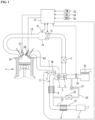
- FIG. 1 is a system configuration diagram of an internal combustion engine 1 to which one embodiment of the present invention is applied.
- the internal combustion engine 1 is mounted for power generation in a series hybrid vehicle.
- the series hybrid vehicle is a hybrid vehicle of the type that runs by driving a generator by an internal combustion engine and driving a motor with power generated by driving of the generator.
- the series hybrid vehicle has: a motor/generator that mainly functions as a generator for generating power; the internal combustion engine 1 used as a power-generating internal combustion engine for driving the power-generating motor/generator according to a power request; a running motor/generator that mainly functions as a motor for driving vehicle drive wheels, a battery that temporarily stores the generated power and an inverter unit that performs power conversion between the battery and the respective motor/generator.
- the internal combustion engine 1 is configured as a four-stroke spark-ignition gasoline engine and is equipped with a turbocharger 2 as shown in FIG. 1 .
- An exhaust turbine 3 of the turbocharger 2 is disposed in an exhaust passage 7 of the internal combustion engine 1.
- An upstream-side catalytic converter 8 and a downstream-side catalytic converter 9, each using e.g. a three-way catalyst, are disposed in the exhaust passage at positions downstream of the exhaust turbine 3.
- the upstream-side catalytic converter 8 is fixed to an outlet portion of the exhaust turbine in an engine room of the internal combustion engine; and the downstream-side catalytic converter 9 is fixed in position under the floor of the vehicle body.
- An exhaust muffler 11 is disposed in a further downstream part of the exhaust passage 7 such that the exhaust passage 7 is open to the outside through the exhaust muffler 11.
- the turbocharger 2 has: a bypass passage 4a that provides communication between outlet and inlet sides of the exhaust passage 3 for boost pressure control; and an electrically-operable waste gate valve 4 that opens and closes the bypass passage 4a.
- a compressor 6 of the turbocharger 2 is disposed in an intake passage 14 of the internal combustion engine 1.
- An electronically-controllable throttle valve 15 for controlling an intake air amount is disposed in the intake passage 14 at a position downstream of the compressor 6.
- the throttle valve 15 is positioned in an inlet portion of a collector part 16.
- a part of the intake passage 14 downstream of the collector part 16 is branched, as an intake manifold, toward the respective cylinders.
- a water-cooled intercooler 17 for cooling turbocharged intake air is disposed in a part of the intake passage 4 upstream of the collector part 16, i.e., between the compressor 6 and the collector part 16.
- a pressure sensor 18 for detecting an intake air pressure in the collector part 16 (as boost pressure) is fixed to the collector part 16.
- the internal combustion engine 1 may alternatively be a naturally aspirated engine without a supercharger.
- An air cleaner 23 is disposed in the most upstream part of the intake passage 14.
- An airflow meter 24 for detecting an intake air amount is disposed in the intake passage at a position downstream of the air cleaner 23.
- An exhaust gas recirculation passage 26 is provided between the exhaust passage 7 and the intake passage 14 to recirculate a part of exhaust gas into the intake system.
- the exhaust recirculation passage 26 has one, upstream end portion branched from the exhaust passage 7 at a position downstream of the upstream-side catalytic converter 8 and the other, downstream end portion connected to the intake passage 14 at a position upstream of the compressor 6.
- An exhaust recirculation control valve 27 whose opening is adjusted according to operating conditions is provided at a midpoint in the exhaust recirculation passage 26.
- An EGR gas cooler 28 for cooling recirculated exhaust gas is disposed in the exhaust recirculation gas passage at a position closer to the exhaust passage 7 than the exhaust gas recirculation control valve 27.
- An air-fuel ratio sensor 31 is disposed on an inlet side of the upstream-side catalytic converter 8.
- An oxygen sensor 32 is disposed on an inlet side of the downstream-side catalytic converter 9.
- An exhaust gas temperature sensor 33 is disposed on an outlet side of the downstream-side catalytic converter 9.
- the internal combustion engine 1 is comprehensively controlled by an engine controller 12.
- an engine controller 12 To the engine controller 12, there are inputted detection signals from various sensors including not only the airflow meter 24 and the pressure sensor 18, but also a crank angle sensor 34 for detecting an engine rotation speed, a coolant temperature sensor 35 for detecting a coolant temperature, an accelerator opening sensor 36 for detecting an amount of depression of an accelerator pedal operated by a driver, and the like. Based on these detection signals, the engine controller 12 optimally controls the fuel injection amount and timing of a fuel injection valve 37, the ignition timing of a spark plug 38, the opening of the throttle valve 15, the opening of the waste gate valve 4, the opening of the exhaust gas recirculation control valve 27 and the like.
- the internal combustion engine 1 has an intake-side variable valve timing mechanism for varying the valve timing of intake valves 41 and an exhaust-side variable valve timing mechanism for varying the valve timing of exhaust valves 42 in the present embodiment.
- the engine controller 12 also controls these variable valve timing mechanisms as appropriate.
- the engine controller 12 executes a predetermined catalyst warm-up control routine at a cold start of the internal combustion engine 1 for early activation of the catalytic converters 8 and 9.
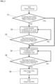
- FIG. 2 is a flowchart of the catalyst warm-up control routine executed by the engine controller 12.
- the routine of FIG. 2 is initiated concurrently with starting of the internal combustion engine 1.
- the internal combustion engine 1 is started upon the generation of a power generation request after the starting of the vehicle.
- step 1 it is judged in step 1 whether the temperature of the upstream-side catalytic converter 8 at the starting of the internal combustion engine 1 is higher than or equal to a catalyst activation temperature. This judgment is made by estimating the catalyst temperature based on the information about the catalyst temperature at the end of the previous trip (i.e. at the time of key-off event) (as determined from the detection temperature of the exhaust gas temperature sensor 33) and the time lapsed from the end of the previous trip, and then, comparing the estimated catalyst temperature with a given threshold value (corresponding to the catalyst activation temperature). When the temperature of the upstream-side catalytic converter 8 has reached the activation temperature, the routine proceeds to the processing of step 4 and subsequent steps.
- step 2 the internal combustion engine 1 is operated at relatively low load and low engine rotation speed with significant ignition timing retardation for catalyst warm-up.
- the ignition timing retardation causes an increase of the exhaust gas temperature and shifts the center of gravity of combustion to a retarded side, thereby promoting catalyst warm-up especially of the upstream-side catalytic converter 8.
- step 3 the warm-up state of the upstream-side catalytic converter 8 is estimated. More specifically, this estimation is done as follows.
- the amount of heat input to the upstream-side catalytic converter 8 (that is, the amount of heat released from the exhaust port and transferred to the upstream-side catalytic converter 8) per cycle is calculated based on the operating parameters of the internal combustion engine 1 including the engine rotation speed and load, the ignition timing (retard amount), the valve timings of the intake and exhaust valves 41 and 42, the exhaust gas recirculation rate, the fuel injection timing, the fuel pressure and the like.
- the calculation results are successively summed and accumulated.
- the thus-obtained heat input amount is compared with a given threshold value (Q1).
- step 3 it is judged that the warm-up of the upstream-side catalytic converter 8 has been completed when the heat input amount is larger than or equal to the threshold value (Q1). Until the heat input amount reaches the threshold value (Q1), the routine goes back from step 3 to step 2 whereby the relatively low-speed, low-load operation of the internal combustion engine with significant ignition timing retardation is continued. The warm-up completion judgment of step 3 is made repeatedly. During this period of time, the internal combustion engine 1 is continuously operated, without being stopped, even when the output of the power generation request to the internal combustion engine 1 ceases.
- the heat input amount threshold value (Q1) used for the judgment of step 3 may be set variably in accordance with the temperature of the upstream-side catalytic converter 8 at the starting of the engine as determined in step 1, or may be set constant regardless of the temperature of the upstream-side catalytic converter 8 at the starting of the engine.
- step 4 the internal combustion engine 1 is kept operated by stopping the ignition timing retardation and relatively increasing the engine rotation speed and load. More specifically, the ignition timing is set in the vicinity of MBT; and the engine rotation speed and load are set in the vicinity of the optimal fuel consumption point. In other words, the operation of the internal combustion engine 1 is continued so as to allow catalyst warm-up of the downstream-side catalytic converter 9 while avoiding an excessive deterioration of fuel efficiency.
- the routine immediately goes to step 4 whereby the operation of the internal combustion engine 1 in the vicinity of the optimal fuel consumption point is started with the ignition timing set in the vicinity of MBT.
- the warm-up state of the downstream-side catalytic converter 9 is estimated in step 5. More specifically, this estimation is done in the same manner as in step 3.
- the amount of heat input to the downstream-side catalytic converter 9 (that is, the amount of heat released from the exhaust port and transferred to the downstream-side catalytic converter 9 via the upstream-side catalytic converter 8) per cycle is calculated based on the operating parameters of the internal combustion engine 1 including the engine rotation speed and load, the ignition timing (retard amount), the valve timings of the intake and exhaust valves 41 and 42, the exhaust gas recirculation rate, the fuel injection timing, the fuel pressure and the like.
- the calculation results are successively summed and accumulated.
- the thus-obtained heat input amount is compared with a given threshold value (Q2). It is judged that the warm-up of the downstream-side catalytic converter 9 has been completed when the heat input amount is larger than or equal to the threshold value (Q2). Until the heat input amount reaches the threshold value (Q2), the routine goes back from step 5 to step 4 whereby the operation of the internal combustion engine in the vicinity of the optical fuel consumption point is continued without ignition timing retardation.
- the warm-up completion judgment of step 5 is made repeatedly. During this period of time, the internal combustion engine 1 is continuously operated, without being stopped, even when the power generation request to the internal combustion engine 1 ceases.
- the heat input amount threshold value (Q2) used for the judgment of step 5 may be set variably in accordance with the temperature of the downstream-side catalytic converter 9 at the starting of the engine (which can be estimated separately from the temperature of the upstream-side catalytic converter 8 or be determined from the estimated temperature of the upstream-side catalytic converter 8), or may be set constant regardless of the temperature of the downstream-side catalytic converter 9 at the starting of the engine.
- step 6 stopping of the internal combustion engine 1 according to the power generation request is permitted. With this, the internal combustion engine 1 is stopped at the time when the power generation request ceases.
- the operation of the internal combustion engine 1 is appropriately controlled in such a manner that the catalyst temperature does not becomes lower than the activation temperature.
- the operation of the internal combustion engine 1 is continued, irrespective of the power generation respect, until the completion of the catalyst warm-up of both of the upstream-side catalytic converter 8 and the downstream-side catalytic converter 9 after the initial starting of the internal combustion engine 1. Therefore, the upstream-side catalytic converter 8 and the downstream-side catalytic converter 9 reliably ensure exhaust gas purification performance.
- the internal combustion engine is operated at relatively low speed and low load with significant ignition timing retardation. This enables early activation of the upstream-side catalytic converter 8 while minimizing a deterioration of exhaust performance during the time up until the activation of the upstream-side catalytic converter 8.
- the internal combustion engine is operated in the vicinity of the optimal fuel consumption point with the normal ignition timing in the vicinity of MBT. This enables activation of the downstream-side catalytic converter 9 while suppressing a deterioration of fuel efficiency.
- FIG. 3 is a block diagram for the catalyst warm-up control. It is herein noted that there is no difference between the control contents shown in this block diagram and the control contents shown in the flowchart of FIG. 2 .
- the information about the catalyst temperature of the upstream-side catalytic converter 8 at the end of the previous trip i.e. at the time of key-off event
- the catalyst temperature of the upstream-side catalytic converter 8 at the starting of the internal combustion engine 1 is determined in the block B2.
- the warm-up completion judgment is made by comparing the determined catalyst temperature of the upstream-side catalytic converter 8 with the threshold value (criteria value) set in the block B4.
- the amount of heat input to the upstream-side catalytic converter 8 is calculated using various parameters (such as engine rotation speed and load, ignition timing (retard amount), valve timings, exhaust gas recirculation rate, fuel injection timing and fuel pressure) sent from the block B6.
- the calculated heat input amount is compared with the threshold value (criteria value) Q1 set in the block B8. When the calculated heat input amount reaches the threshold value Q1, the internal combustion engine is shifted to operation at rotation speed and load in the vicinity of the optimal fuel consumption point with the normal ignition timing in the vicinity of MBT.
- the amount of heat input to the downstream-side catalytic converter 9 is calculated using various parameters (such as engine rotation speed and load, ignition timing, valve timings, exhaust gas recirculation rate, fuel injection timing and fuel pressure) sent from the block B10.
- the calculated heat input amount is compared with the threshold value (criteria value) Q2 set in the block B12. When the calculated heat input amount reaches the threshold value Q2, stopping of the internal combustion engine 1 is permitted in the block B13.
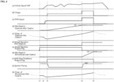
- FIG. 4 shows a time chart of changes of the respective functions and parameters under the catalyst warm-up control according to the present embodiment. From the top side in the figure, shown are the changes of: (a) the vehicle speed; (b) the torque (load) of the internal combustion engine; (c) the rotation speed of the internal combustion engine 1; (d) the calculated heat input amount of the upstream-side catalytic converter 8; (e) the temperature of the upstream-side catalytic converter 8; (f) the ignition timing retard operation end judgment flag; (g) the ignition timing retard operation request flag; (h) the calculated heat input amount of the downstream-side catalytic converter 9; (i) the stop prohibition request flag for requesting stopping of the internal combustion engine 1; (j) the ignition timing; and (k) the temperature of the downstream-side catalytic converter 9.
- the vehicle is placed in a key-on state at time t1.
- the ignition timing retard operation request flag is turned on as shown in the section (g).
- the internal combustion engine 1 is then started.
- the autonomous operation of the internal combustion engine 1 begins at time t3.
- the retard operation for catalyst warm-up is performed, with the ignition timing significantly retarded and the engine rotation speed and load set relatively low, according to the ignition timing retard operation request flag as shown in the section (g).
- the heat input amount of the upstream-side catalytic converter 8 increases as shown in the section (d).
- the heat input amount of the upstream-side catalytic converter reaches the given threshold value Q1.
- the ignition timing retard operation request flag is turned off as shown in the section (g). The internal combustion engine is then shifted to the operation in the vicinity of the optimal fuel consumption point where the engine rotation speed and load are set relatively high with the ignition timing set in the vicinity of MBT.
- the heat input amount of the downstream-side catalytic converter 9 increases as shown in the section (h).
- the heat input amount of the downstream-side catalytic converter 9 reaches the given threshold value Q2.
- the stop prohibition request flag is turned off.
- the example of FIG. 4 is based on the assumption that the power generation request ceases before time t5.
- the operation of the internal combustion engine 1 is stopped (see the sections (b) and (c)) when the stop prohibition request flag is turned off at time t5. From time t5 onward, the so-called EV running is performed with the supply of power from the battery.
- the operation of the internal combustion engine 1 is not stopped irrespective of the power generation request, In other words, the operation of the internal combustion engine 1 is continued until the completion of catalyst warm-up of both of the upstream-side catalytic converter 8 and the downstream-side catalytic converter 9 as described above.
- the temperature of the downstream-side catalytic converter 9 has been gradually increasing since before time t4.
- the summing/accumulation of the heat input to the downstream-side catalytic converter 9 is started from time t4. This leads to simplification of the control.
- the period from time t3 to time 4 corresponds to the claimed first period; and the period from time t4 to time 5 corresponds to the claimed second period.
- the estimation of the temperatures and warm-up states of the upstream-side catalytic converter 8 and the downstream-side catalytic converter 9 can be done by various methods.
- the temperatures and warm-up states of the catalytic converters can be determined by direct detection with the use of temperature sensors.
- the present invention is also applicable to the case where an intermediate catalytic converter is additionally disposed between the upstream-side catalytic converter 8 and the downstream-side catalytic converter 9.
Landscapes
- Engineering & Computer Science (AREA)
- Mechanical Engineering (AREA)
- Combustion & Propulsion (AREA)
- Chemical & Material Sciences (AREA)
- Transportation (AREA)
- Automation & Control Theory (AREA)
- General Engineering & Computer Science (AREA)
- Theoretical Computer Science (AREA)
- Signal Processing (AREA)
- Mathematical Physics (AREA)
- Physics & Mathematics (AREA)
- Combined Controls Of Internal Combustion Engines (AREA)
- Exhaust Gas After Treatment (AREA)
- Hybrid Electric Vehicles (AREA)
- Control Of Driving Devices And Active Controlling Of Vehicle (AREA)
Applications Claiming Priority (1)
| Application Number | Priority Date | Filing Date | Title |
|---|---|---|---|
| PCT/JP2020/047407 WO2022130614A1 (ja) | 2020-12-18 | 2020-12-18 | 内燃機関の触媒暖機制御方法および触媒暖機制御装置 |
Publications (2)
| Publication Number | Publication Date |
|---|---|
| EP4265495A1 true EP4265495A1 (de) | 2023-10-25 |
| EP4265495A4 EP4265495A4 (de) | 2024-01-03 |
Family
ID=82059324
Family Applications (1)
| Application Number | Title | Priority Date | Filing Date |
|---|---|---|---|
| EP20966001.8A Withdrawn EP4265495A4 (de) | 2020-12-18 | 2020-12-18 | Verfahren zur steuerung der erwärmung eines katalysators für einen verbrennungsmotor und vorrichtung zur steuerung der erwärmung eines katalysators |
Country Status (5)
| Country | Link |
|---|---|
| US (1) | US12085033B2 (de) |
| EP (1) | EP4265495A4 (de) |
| JP (1) | JP7380914B2 (de) |
| CN (1) | CN116568542B (de) |
| WO (1) | WO2022130614A1 (de) |
Families Citing this family (2)
| Publication number | Priority date | Publication date | Assignee | Title |
|---|---|---|---|---|
| WO2025238742A1 (ja) * | 2024-05-15 | 2025-11-20 | 日産自動車株式会社 | 内燃機関の制御方法及び内燃機関の制御装置 |
| WO2025262868A1 (ja) * | 2024-06-20 | 2025-12-26 | 日産自動車株式会社 | 内燃機関の加速時制御方法および装置 |
Family Cites Families (17)
| Publication number | Priority date | Publication date | Assignee | Title |
|---|---|---|---|---|
| JPH07229419A (ja) | 1994-02-18 | 1995-08-29 | Toyota Motor Corp | 内燃機関の触媒暖機制御装置 |
| JP3554096B2 (ja) * | 1996-01-18 | 2004-08-11 | 株式会社日立製作所 | 内燃機関用制御装置 |
| JP3414303B2 (ja) * | 1998-03-17 | 2003-06-09 | 日産自動車株式会社 | 直噴火花点火式内燃機関の制御装置 |
| JP4560978B2 (ja) * | 2001-03-30 | 2010-10-13 | マツダ株式会社 | ターボ過給機付火花点火式直噴エンジン |
| EP1245815B1 (de) | 2001-03-30 | 2006-06-07 | Mazda Motor Corporation | Direkteinspritz- und Funkengezündeter Motor mit einer Turboaufladevorrichtung, Steuermethode und rechnerlesbares Speichermedium dafür |
| JP3705361B2 (ja) * | 2002-01-31 | 2005-10-12 | 三菱自動車工業株式会社 | ハイブリッド車両の制御装置 |
| JP4557962B2 (ja) * | 2006-12-28 | 2010-10-06 | トヨタ自動車株式会社 | 内燃機関の制御装置 |
| JP2009036021A (ja) * | 2007-07-31 | 2009-02-19 | Denso Corp | 内燃機関の過給機制御装置及び排気圧力制御方法 |
| JP5899674B2 (ja) * | 2011-06-15 | 2016-04-06 | 日産自動車株式会社 | ハイブリッド車両の制御装置 |
| JP5831501B2 (ja) * | 2013-06-05 | 2015-12-09 | トヨタ自動車株式会社 | 内燃機関 |
| JP5929884B2 (ja) | 2013-12-19 | 2016-06-08 | トヨタ自動車株式会社 | ハイブリッド車両 |
| JP6149841B2 (ja) * | 2014-10-22 | 2017-06-21 | トヨタ自動車株式会社 | ハイブリッド自動車 |
| JP2016112962A (ja) | 2014-12-12 | 2016-06-23 | 日産自動車株式会社 | ハイブリッド車両の制御装置 |
| JP2016120853A (ja) | 2014-12-25 | 2016-07-07 | トヨタ自動車株式会社 | ハイブリッド自動車の制御装置 |
| JP6319241B2 (ja) | 2015-09-11 | 2018-05-09 | マツダ株式会社 | 発電機駆動用エンジン搭載の自動車 |
| JP6465073B2 (ja) * | 2016-05-20 | 2019-02-06 | トヨタ自動車株式会社 | 自然吸気ガソリンエンジンの制御装置 |
| JP6835235B2 (ja) * | 2017-08-30 | 2021-02-24 | 日産自動車株式会社 | 内燃機関の制御方法及び内燃機関の制御装置 |
-
2020
- 2020-12-18 EP EP20966001.8A patent/EP4265495A4/de not_active Withdrawn
- 2020-12-18 JP JP2022569658A patent/JP7380914B2/ja active Active
- 2020-12-18 WO PCT/JP2020/047407 patent/WO2022130614A1/ja not_active Ceased
- 2020-12-18 CN CN202080107897.1A patent/CN116568542B/zh active Active
- 2020-12-18 US US18/268,084 patent/US12085033B2/en active Active
Also Published As
| Publication number | Publication date |
|---|---|
| US20240035424A1 (en) | 2024-02-01 |
| EP4265495A4 (de) | 2024-01-03 |
| JPWO2022130614A1 (de) | 2022-06-23 |
| WO2022130614A1 (ja) | 2022-06-23 |
| CN116568542A (zh) | 2023-08-08 |
| JP7380914B2 (ja) | 2023-11-15 |
| US12085033B2 (en) | 2024-09-10 |
| CN116568542B (zh) | 2025-10-14 |
Similar Documents
| Publication | Publication Date | Title |
|---|---|---|
| US7869912B2 (en) | Controlling device of hybrid vehicle | |
| US9458812B2 (en) | Engine control systems and methods for minimizing fuel consumption | |
| US9151233B2 (en) | Vehicle controller | |
| US6829888B2 (en) | Method for controlling the starting of an internal combustion engine | |
| US12085033B2 (en) | Catalyst warm-up control method for internal combustion engine, and catalyst warm-up control device | |
| US11724686B2 (en) | Method of reducing cold start emissions in hybrid electric vehicles | |
| CN111417772B (zh) | 车辆用内燃机的控制方法以及控制装置 | |
| JP4086005B2 (ja) | ディーゼルハイブリッド車両における低圧縮比エンジンの暖機制御方法 | |
| JP7676924B2 (ja) | ハイブリッド車両の暖機制御方法および暖機制御装置 | |
| WO2023007530A1 (ja) | 内燃機関の触媒暖機制御方法および装置 | |
| JP2019127849A (ja) | 内燃機関の触媒暖機制御方法および触媒暖機制御装置 | |
| JP5040702B2 (ja) | 内燃機関の制御装置 | |
| JP7477049B2 (ja) | ハイブリッド車両の制御方法及びハイブリッド車両の制御装置 | |
| JP6763489B2 (ja) | 車両用内燃機関の制御方法および制御装置 | |
| JP7757868B2 (ja) | 車両の制御システム | |
| WO2026069448A1 (ja) | 車両の制御方法及び車両の制御装置 | |
| JP2008038641A (ja) | 内燃機関の制御装置 | |
| US11441497B2 (en) | Internal combustion engine control method and internal combustion engine control device | |
| WO2026053279A1 (ja) | 内燃機関の制御方法及び内燃機関の制御装置 | |
| JP2023017145A (ja) | ハイブリッド車両の制御方法及びハイブリッド車両の制御装置 | |
| JP2001221112A (ja) | 内燃機関の暖機装置 |
Legal Events
| Date | Code | Title | Description |
|---|---|---|---|
| STAA | Information on the status of an ep patent application or granted ep patent |
Free format text: STATUS: THE INTERNATIONAL PUBLICATION HAS BEEN MADE |
|
| PUAI | Public reference made under article 153(3) epc to a published international application that has entered the european phase |
Free format text: ORIGINAL CODE: 0009012 |
|
| STAA | Information on the status of an ep patent application or granted ep patent |
Free format text: STATUS: REQUEST FOR EXAMINATION WAS MADE |
|
| 17P | Request for examination filed |
Effective date: 20230703 |
|
| AK | Designated contracting states |
Kind code of ref document: A1 Designated state(s): AL AT BE BG CH CY CZ DE DK EE ES FI FR GB GR HR HU IE IS IT LI LT LU LV MC MK MT NL NO PL PT RO RS SE SI SK SM TR |
|
| A4 | Supplementary search report drawn up and despatched |
Effective date: 20231205 |
|
| RIC1 | Information provided on ipc code assigned before grant |
Ipc: B60W 20/13 20160101ALI20231129BHEP Ipc: B60W 40/00 20060101ALI20231129BHEP Ipc: B60W 30/188 20120101ALI20231129BHEP Ipc: B60W 10/06 20060101ALI20231129BHEP Ipc: B60K 6/46 20071001ALI20231129BHEP Ipc: B60W 20/16 20160101AFI20231129BHEP |
|
| DAV | Request for validation of the european patent (deleted) | ||
| DAX | Request for extension of the european patent (deleted) | ||
| STAA | Information on the status of an ep patent application or granted ep patent |
Free format text: STATUS: THE APPLICATION HAS BEEN WITHDRAWN |
|
| 18W | Application withdrawn |
Effective date: 20250403 |