EP4264050B1 - Kompressor - Google Patents
Kompressor Download PDFInfo
- Publication number
- EP4264050B1 EP4264050B1 EP21839839.4A EP21839839A EP4264050B1 EP 4264050 B1 EP4264050 B1 EP 4264050B1 EP 21839839 A EP21839839 A EP 21839839A EP 4264050 B1 EP4264050 B1 EP 4264050B1
- Authority
- EP
- European Patent Office
- Prior art keywords
- compressor
- bypass
- piston
- bore
- leakage path
- Prior art date
- Legal status (The legal status is an assumption and is not a legal conclusion. Google has not performed a legal analysis and makes no representation as to the accuracy of the status listed.)
- Active
Links
Images



Classifications
-
- F—MECHANICAL ENGINEERING; LIGHTING; HEATING; WEAPONS; BLASTING
- F04—POSITIVE - DISPLACEMENT MACHINES FOR LIQUIDS; PUMPS FOR LIQUIDS OR ELASTIC FLUIDS
- F04B—POSITIVE-DISPLACEMENT MACHINES FOR LIQUIDS; PUMPS
- F04B39/00—Component parts, details, or accessories, of pumps or pumping systems specially adapted for elastic fluids, not otherwise provided for in, or of interest apart from, groups F04B25/00 - F04B37/00
- F04B39/04—Measures to avoid lubricant contaminating the pumped fluid
- F04B39/041—Measures to avoid lubricant contaminating the pumped fluid sealing for a reciprocating rod
-
- F—MECHANICAL ENGINEERING; LIGHTING; HEATING; WEAPONS; BLASTING
- F04—POSITIVE - DISPLACEMENT MACHINES FOR LIQUIDS; PUMPS FOR LIQUIDS OR ELASTIC FLUIDS
- F04B—POSITIVE-DISPLACEMENT MACHINES FOR LIQUIDS; PUMPS
- F04B37/00—Pumps having pertinent characteristics not provided for in, or of interest apart from, groups F04B25/00 - F04B35/00
- F04B37/10—Pumps having pertinent characteristics not provided for in, or of interest apart from, groups F04B25/00 - F04B35/00 for special use
- F04B37/12—Pumps having pertinent characteristics not provided for in, or of interest apart from, groups F04B25/00 - F04B35/00 for special use to obtain high pressure
-
- F—MECHANICAL ENGINEERING; LIGHTING; HEATING; WEAPONS; BLASTING
- F04—POSITIVE - DISPLACEMENT MACHINES FOR LIQUIDS; PUMPS FOR LIQUIDS OR ELASTIC FLUIDS
- F04B—POSITIVE-DISPLACEMENT MACHINES FOR LIQUIDS; PUMPS
- F04B39/00—Component parts, details, or accessories, of pumps or pumping systems specially adapted for elastic fluids, not otherwise provided for in, or of interest apart from, groups F04B25/00 - F04B37/00
- F04B39/0005—Component parts, details, or accessories, of pumps or pumping systems specially adapted for elastic fluids, not otherwise provided for in, or of interest apart from, groups F04B25/00 - F04B37/00 adaptations of pistons
-
- F—MECHANICAL ENGINEERING; LIGHTING; HEATING; WEAPONS; BLASTING
- F04—POSITIVE - DISPLACEMENT MACHINES FOR LIQUIDS; PUMPS FOR LIQUIDS OR ELASTIC FLUIDS
- F04B—POSITIVE-DISPLACEMENT MACHINES FOR LIQUIDS; PUMPS
- F04B39/00—Component parts, details, or accessories, of pumps or pumping systems specially adapted for elastic fluids, not otherwise provided for in, or of interest apart from, groups F04B25/00 - F04B37/00
- F04B39/04—Measures to avoid lubricant contaminating the pumped fluid
-
- F—MECHANICAL ENGINEERING; LIGHTING; HEATING; WEAPONS; BLASTING
- F16—ENGINEERING ELEMENTS AND UNITS; GENERAL MEASURES FOR PRODUCING AND MAINTAINING EFFECTIVE FUNCTIONING OF MACHINES OR INSTALLATIONS; THERMAL INSULATION IN GENERAL
- F16J—PISTONS; CYLINDERS; SEALINGS
- F16J15/00—Sealings
- F16J15/002—Sealings comprising at least two sealings in succession
- F16J15/006—Sealings comprising at least two sealings in succession with division of the pressure
-
- F—MECHANICAL ENGINEERING; LIGHTING; HEATING; WEAPONS; BLASTING
- F16—ENGINEERING ELEMENTS AND UNITS; GENERAL MEASURES FOR PRODUCING AND MAINTAINING EFFECTIVE FUNCTIONING OF MACHINES OR INSTALLATIONS; THERMAL INSULATION IN GENERAL
- F16J—PISTONS; CYLINDERS; SEALINGS
- F16J15/00—Sealings
- F16J15/16—Sealings between relatively-moving surfaces
- F16J15/164—Sealings between relatively-moving surfaces the sealing action depending on movements; pressure difference, temperature or presence of leaking fluid
-
- F—MECHANICAL ENGINEERING; LIGHTING; HEATING; WEAPONS; BLASTING
- F16—ENGINEERING ELEMENTS AND UNITS; GENERAL MEASURES FOR PRODUCING AND MAINTAINING EFFECTIVE FUNCTIONING OF MACHINES OR INSTALLATIONS; THERMAL INSULATION IN GENERAL
- F16J—PISTONS; CYLINDERS; SEALINGS
- F16J15/00—Sealings
- F16J15/16—Sealings between relatively-moving surfaces
- F16J15/26—Sealings between relatively-moving surfaces with stuffing-boxes for rigid sealing rings
-
- F—MECHANICAL ENGINEERING; LIGHTING; HEATING; WEAPONS; BLASTING
- F16—ENGINEERING ELEMENTS AND UNITS; GENERAL MEASURES FOR PRODUCING AND MAINTAINING EFFECTIVE FUNCTIONING OF MACHINES OR INSTALLATIONS; THERMAL INSULATION IN GENERAL
- F16J—PISTONS; CYLINDERS; SEALINGS
- F16J15/00—Sealings
- F16J15/56—Other sealings for reciprocating rods
-
- F—MECHANICAL ENGINEERING; LIGHTING; HEATING; WEAPONS; BLASTING
- F16—ENGINEERING ELEMENTS AND UNITS; GENERAL MEASURES FOR PRODUCING AND MAINTAINING EFFECTIVE FUNCTIONING OF MACHINES OR INSTALLATIONS; THERMAL INSULATION IN GENERAL
- F16J—PISTONS; CYLINDERS; SEALINGS
- F16J9/00—Piston-rings, e.g. non-metallic piston-rings, seats therefor; Ring sealings of similar construction
- F16J9/12—Details
- F16J9/22—Rings for preventing wear of grooves or like seatings
Definitions
- the present invention relates to a compressor.
- Piston compressors usually comprise a piston with a piston rod connected to the piston.
- the piston oscillates in a liner and usually comprises several piston rings as seals, which seal the high-pressure side, i.e. the compression chamber, from the low-pressure side, i.e. where the piston rod begins.
- a seal in the form of a piston rod packing is also usually arranged on the piston rod.
- the piston rod packing comprises several chamber discs that lie axially against one another and form chambers within which seals with one or more sealing rings are arranged.
- the sealing rings also seal a high-pressure side, on which the piston is located, from a low-pressure side, on which the compressor drive is located.
- a sealing packing for piston rods is available from US 3,544,118 known.
- the DE 91 90 040 U1 and the DE 10 2010 034 870 A1 reveal seals from the field of internal combustion engines.
- the KR 10 2009 0108925 A discloses a piston for a gas compressor.
- the JP S60-88844 A and the KR 2001 0065988 A each reveal a seal for an internal combustion engine.
- Piston compressors can be used to compress hydrogen. Hydrogen compression is, for example, important for hydrogen filling stations necessary. The pressures required there can be, for example, 400 bar for buses and 900 bar for cars.
- the object of the invention was to create a way to enable compression of gases with high pressure differences and high velocities.
- the compressor comprises a stationary part and a part oscillating along a main axis as well as a leakage path running axially between the stationary part and the oscillating part. Between the stationary part and the oscillating part there are several axially successive arranged chambers running in a ring around the main axis. A seal is arranged in at least one chamber, which closes or reduces the leakage path, i.e. reduces or prevents leakage along the leakage path.
- the compressor is characterized in that at least one bypass is provided, which fluidically connects two chambers to one another.
- the compressor is in particular a piston compressor.
- the leakage path is basically present because the stationary and oscillating parts do not touch each other.
- the seals reduce the leakage along the leakage path, with the focus of development to date being on continually reducing the leakage.
- conventional piston rod seals starting from the high-pressure side, the reduction of the dynamic pressure component takes place mainly at the first seal and the reduction of the static pressure component mainly at the last seal.
- the situation is similar with the piston rings on a piston. The first and last seals are therefore subject to the greatest load.
- the inventors have recognized that it is particularly useful in the case of high pressure differences to distribute the pressure difference (difference between the high pressure side and the low pressure side) more homogeneously across the individual seals via a sealing arrangement, i.e. an arrangement of several seals in several chambers arranged axially one behind the other. This reduces the pressure difference per seal (pressure difference in front of and behind the seal) at the first and last seal.
- the compressor can be designed in such a way that the pv limit is not reached at any of the seals when used as intended.
- the invention therefore continues to seal the leakage path itself as well as possible and at the same time a
- a specifically defined bypass is provided which allows a predefined leakage.
- the homogeneous pressure distribution is thus achieved through targeted leakage via the bypass or bypasses between the individual chambers of the compressor.
- the bypasses are designed in such a way that a homogeneous pressure distribution is achieved across the sealing arrangement.
- the invention can be used both for the sealing arrangement on a piston of a compressor and in a piston rod packing of a compressor.
- the stationary part can therefore be a liner and the oscillating part a piston.
- the stationary part can be a packing housing and the oscillating part a piston rod.
- the leakage through the bypass is defined in particular by its minimum cross-section, i.e. the cross-section at its narrowest point. It has been shown that a minimum cross-section M ⁇ 2 mm 2 , in particular M ⁇ 1.5 mm 2 is effective, especially in the application range of pressure differences > 300 bar.
- the minimum cross-section is preferably M > 0.1 mm 2 .
- Bypasses can be provided in the stationary part, in particular the packing housing, or the oscillating part, in particular the piston, or in the seals.
- the seals in particular, the introduction of holes and/or millings in the sealing rings or in support rings, which enable targeted leakage between the chambers.
- the hole/milling is not located in the area of the leakage path.
- the seal is preferably made of a rigid material (e.g. plastics with an elastic modulus > 5000 MPa and/or metals) in order to achieve targeted leakage.
- the bypass is provided in addition to the leakage path. This means that the bypass is provided at a location where no section of the leakage path is formed. On a sealing ring, for example, a section of the leakage path is formed on the radial sealing surface, since a small amount of leakage can occur there. In such a case, the bypass could, for example, preferably be across the sealing ring, but not in the area of the sealing surface.
- the bypass is preferably formed by at least one hole.
- a hole can be precisely adjusted in terms of its size, so that it is basically possible to define the minimum cross-section and thus the leakage solely by the diameter of the hole. At the same time, a hole is comparatively easy to produce, so that the manufacturing costs of the compressor do not increase significantly.
- a single hole can basically also be formed in several drilling processes and then have a kink, for example. A hole does not necessarily have to be straight.
- the piston can be either a so-called assembled piston or a piston with a one-piece piston body.
- An assembled piston has several disc bodies in the form of piston discs, which are arranged one behind the other in the axial direction and together, optionally supplemented by further disc bodies, form the piston body.
- the piston body has both in one-piece as well as in built form preferably has a cylindrical core and a plurality of ring-shaped projections running circumferentially around the core, between which radially outward-facing grooves for the seals are formed.
- the grooves are partially closed by the cylinder liner, with remaining gaps forming sections of the leakage path. The grooves thus form the chambers for the seals together with the cylinder liner.
- the piston rod packing is basically "built” and then has several disc bodies in the form of chamber discs, which are arranged one behind the other in the axial direction, each with a central bore and form the packing housing through which the piston rod runs.
- the chamber discs form several radially inward-facing grooves, which are partially closed by the piston rod, with the remaining gaps again forming sections of the leakage path.
- the grooves together with the circumferential surface of the piston rod, form the chambers for the seals.
- the disc bodies can be screwed together.
- the piston or the packing housing has a plurality of disk bodies which are arranged one behind the other in the axial direction, wherein the disk bodies have a first axial surface and a second axial surface arranged opposite the disk body as well as a radial surface, and wherein the bore extends between the first axial surface and the radial surface and/or between the first axial surface and the second axial surface.
- the radial surface is an inner radial surface or in the case of the piston, an outer radial surface.
- the radial surface can also be the groove base of the grooves formed, which can then also be referred to as the chamber base of the chambers formed.
- the bore preferably runs parallel to the main axis, at least in sections, particularly in the case of seals and disc bodies. This simplifies the production of the bore.
- the bore preferably runs at least partially through the core. In this way, for example, two groove bases of adjacent chambers can be connected to one another by drilling across the core.
- the bore particularly preferably runs through the center of the piston, i.e. it crosses the main axis.
- the bypass is provided directly in the area of the leakage path, in particular in the form of a groove.
- Such bypasses can be provided in particular in the disk bodies, particularly preferably in the area of a sealing surface.
- the sealing surface is then preferably flat and the bypass a groove.
- the associated sealing surface of the seal is preferably also flat.
- the sealing surface(s) preferably extend perpendicular to the main axis.
- the groove preferably runs perpendicular to the main axis. If, as described above, a milling is provided in the seal, then progressive wear of the seal leads to the bypass gradually becoming smaller.
- a groove in the less wearing sealing partner does not become smaller or only very slightly smaller over time.
- a bypass in the disk body in the area of the leakage path, in particular in the sealing surface thus retains its predefined cross-section over a long period of time.
- the groove thus represents a preferred embodiment of a bypass.
- bypasses are therefore provided, whereby of each two adjacent bypasses, the bypass which is arranged closer to the high-pressure side of the compressor has a minimum cross-section M which is smaller than or equal to the minimum cross-section M of the bypass which is arranged closer to a low-pressure side of the compressor.
- the bypasses become larger or at least remain the same starting from the high-pressure side towards the low-pressure side.
- the bores of the bypasses are particularly preferably similar and in particular identical and the differences between the bypasses are achieved by the throttle used in each case.
- the throttles are designed differently and in particular have different minimum cross-sections.
- a disk body which is designed for use in a compressor and has a first axial surface, a second axial surface arranged opposite the disk body and a radial surface, and which is characterized by a bypass which runs between the first axial surface and the radial surface and/or between the first axial surface and the second axial surface.
- the radial surface is in particular an inner radial surface or an outer radial surface.
- the bypass of this disk body is preferably a bore.
- a disk body which is designed for use in a compressor and has an inner radial surface and an outer radial surface, wherein a bypass runs between the inner radial surface and an outer radial surface.
- the bypass of this disk body is preferably a groove.
- the disk body can further be developed in the manner described above with regard to the compressor.
- a seal designed for use in a compressor, having a first axial end surface, a second axial end surface, a radial inner surface and a radial outer surface, thereby defining a bypass extending between at least two of the surfaces, i.e. first axial end surface, second axial end surface, radial inner surface and radial outer surface.
- the seal can further be developed in the manner described above with regard to the compressor.
- a disk body or a seal according to the above description in a compressor, preferably a piston compressor, in particular a compressor according to the above description.
- the bushing 120 includes a sliding surface 122, which is an internal, cylindrical peripheral surface.
- the piston 130 is a so-called built-up piston 130.
- the piston 130 comprises a plurality of disk bodies 40, namely a base plate 132 and a plurality of piston disks 140 arranged one behind the other in the axial direction.
- the piston 130 is connected to a piston rod 230.
- the piston disks 140 together with the base plate 132 form a piston body 150.
- the piston body 150 has a cylindrical core 152 and a plurality of annular projections 154 running circumferentially around the core 152.
- a plurality of grooves 156 are formed between the projections 154, each groove 156 being formed either by two piston disks 140 or by one piston disk 140 and the base plate 132.
- the grooves 156 are partially closed by the liner 120, whereby the piston body 150 together with the liner 120 forms a plurality of chambers 50 arranged axially one behind the other and extending in a ring shape around the main axis.
- the liner 120 does not touch the piston body 150.
- a leakage path L running in the axial direction remains between the liner 120 and the piston 130.
- a seal 60 is arranged in each chamber 50, which closes or reduces the leakage path L.
- the seals 60 are piston rings 160, which are shown here in a simplified manner. Depending on the direction in which the piston 130 moves at a certain point in time, the piston rings 160 rest either on the high-pressure side or the low-pressure side flank of the grooves 156 and seal the leakage path L there.
- the bypasses 70a,b,c offer the gases coming from the high pressure side an opportunity to flow into the next chamber 50 in addition to the leakage path L. In this way, the pressure difference between the high pressure side H and the low pressure side N is gradually and overall homogeneously reduced.
- the piston 30 has a one-piece piston body 150.
- the piston body 150 also comprises a cylindrical core 152 and a plurality of annular, projections 154 extending circumferentially around the core 152.
- the design of the liner 20, the piston rod 230 and the seals 60 is identical to the embodiment according to Figure 1 .
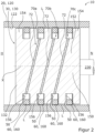
- the bypasses 70a,b,c are also used in the embodiment according to Figure 2 formed by bores 72.
- the bores 72 do not run parallel to the main axis X. Rather, the bores 72 run from the groove base of a groove 156 in a straight line to the groove base of the adjacent groove 156.
- the bores 72 run completely through the core 152 of the piston body 150.
- the bores cross the main axis X.
- Adjacent chambers 50 are thus also connected to one another in this embodiment by the bores 72, so that a homogeneous pressure distribution occurs across all seals 60.
- the Figure 3 shows a detail of a compressor 10 with a packing housing 220 as a stationary part 20 and a piston rod 230 as an oscillating part 30.
- the piston rod 230 oscillates relative to the packing housing 220 along a main axis X between a high-pressure side H and a low-pressure side N.
- the packing housing 220 comprises a plurality of chamber disks 240 as disk body 40, namely a base plate 222, a plurality of main chamber disks 223, a cover plate 224 and a closure plate 226, which are arranged in this order along the main axis X.
- the chamber disks 240 each have a central bore.
- the piston rod 230 runs through the central bores.
- Two adjacent chamber disks 240 together form a groove 228 that is open radially inwards.
- the grooves 228 of the chamber discs 240 are partially closed by the piston rod 230.
- the chamber discs 240 and the Piston rod 230 forms a plurality of chambers 50 arranged axially one behind the other and extending in a ring shape around the main axis, whereby a leakage path L remains between chamber disks 240 and piston rod 230.
- the chamber disks 240 each have a first axial surface 282 and a second axial surface 284 arranged opposite the piston disk 240 as well as an inner radial surface 286 (see Figure 3A ).
- a seal 60 is arranged in each of four of the chambers 50.
- the seals 60 each comprise a support ring 262, a sealing ring 264 and a cover ring 266 (see Figure 3A ).
- the sealing ring 264 and the cover ring 266 are held on the piston rod 230 by hose springs 270.
- the seals 60 can also be constructed differently and comprise more or fewer rings.
- the support ring 262 does not touch the piston rod 230 when used as intended, but is arranged at a radial distance from the piston rod 230.
- the pressure coming from the high pressure side H presses the seal 60 against the chamber disk 240, which is located closer to the low pressure side N.
- the support ring 262 supports the seal 60 in the axial direction on the chamber disk 240.
- the sealing ring 264 rests on the piston rod 230 and thus seals the leakage path L, i.e. it closes the leakage path L completely or partially.
- each of the bores 72 there is a throttle 74 in the form of a screw connection with a perforated plate 76, which is screwed into the bore 72.
- the perforated plate 76 has a hole which defines the minimum cross-section of the respective bypass 70a,b,c,d.
- the holes in the perforated plates 76 of the bypasses 70a,b,c,d have a diameter of 0.4 mm, 0.4 mm, 0.5 mm and 0.6 mm.
- the minimum cross-section from bypass 70a,b,c,d to bypass 70a,b,c,d therefore becomes smaller or remains the same in the direction of the high-pressure side H.
- Support ring 262 shown can be used, for example, in a piston housing 220 according to Figure 3
- the support ring 262 includes a first axial end surface 272, an opposite second axial end surface 274, a radial inner surface 276, and a radial outer surface 278.
- the support ring 262 further comprises a bypass 70 in the form of a bore 72.
- the bore 72 runs in the radial direction from the radial inner surface 276 to the radial outer surface 278.
- the support ring 262 does not rest with its radial inner surface 276 on the piston rod 230, as mentioned above.
- the support ring 262 also does not rest with its radial outer surface 278 on the packing housing 220.
- the bypass 70 of the support ring 262 also connects two adjacent chambers 50 (cf. Figure 3A ).
- the Figure 5 shows a detail of a compressor 10, which is identical in parts to the compressor 10 of the Figure 3
- the compressor 10 has a packing housing 220 as a stationary part 20 and a piston rod 230 as an oscillating part 30.
- the piston rod 230 oscillates relative to the packing housing 220 along a main axis X between a high pressure side H and a low pressure side N.
- the grooves 228 of the chamber disks 240 are partially closed by the piston rod 230.
- the chamber disks 240 and the piston rod 230 form a plurality of chambers 50 arranged axially one behind the other and extending in a ring around the main axis, with a leakage path L remaining between the chamber disks 240 and the piston rod 230.
- the chamber disks 240 each have a first axial surface 282 and a second axial surface 284 arranged opposite the piston disk 240 as well as an inner radial surface 286.
- a seal 60 is arranged in each of four of the chambers 50.
- the seals 60 each comprise a support ring 262, a sealing ring 264 and a cover ring 266 (see Figure 3A ).
- the sealing ring 264 and the cover ring 266 are held on the piston rod 230 by hose springs 270.
- the seals 60 can also be constructed differently and comprise more or fewer rings.
- the support ring 262 does not touch the piston rod 230 when used as intended, but is arranged radially spaced from the piston rod 230.
- the pressure coming from the high-pressure side H presses the seal 60 against the first axial surface 282 of the chamber disk 240.
- the first axial surface 282 thus forms a sealing surface 288.
- the support ring 262 supports the seal 60 in the axial direction on the chamber disk 240.
- the sealing ring 264 rests on the piston rod 230 and thus seals the leakage path L, i.e. it closes the leakage path L completely or partially.
- a bypass 70 in the form of a groove 78 is provided, which fluidically connects two adjacent chambers 50 to one another.
- the groove 78 runs in the first axial surface 282, which is also the sealing surface 288.
- the groove 78 runs completely through the sealing surface 288 in the radial direction. Even if the seal 60 is in full contact with the sealing surface 288, the groove 78 remains open in this way and forms a bypass 70.
- the chamber disc 240 is constructed similarly to the chamber disc 240 of the Figure 5 .
- the chamber disk 240 has a central bore which is enclosed by an inner radial surface 286.
- the chamber disk 240 also has a first axial surface 282, which is simultaneously a sealing surface 288 for a seal (not shown). When used as intended, the seal rests against the sealing surface 288.
- the sealing surface 288 is arranged on an axial projection of the chamber disk 240.
- the axial projection includes an outer radial surface 186.
- the chamber disk 240 has a bypass 70 in the form of a groove 78.
- the groove 78 runs from the outer radial surface 186 to the inner radial surface 286. If the seal rests on the sealing surface 288, gas can continue to flow past the seal through the bypass 70.
- the size of the bypass 70 is predefined, which achieves targeted leakage.
- the groove 78 runs in the radial direction, i.e. perpendicular to a main axis of the chamber disc 240.
Landscapes
- Engineering & Computer Science (AREA)
- General Engineering & Computer Science (AREA)
- Mechanical Engineering (AREA)
- Compressor (AREA)
- Compressors, Vaccum Pumps And Other Relevant Systems (AREA)
- Sealing Devices (AREA)
- Pistons, Piston Rings, And Cylinders (AREA)
Description
- Die vorliegende Erfindung betrifft einen Kompressor.
- Kolbenkompressoren umfassen regelmäßig einen Kolben mit einer sich an den Kolben anschließenden Kolbenstange. Der Kolben oszilliert in einer Laufbuchse und umfasst in der Regel mehrere Kolbenringe als Dichtungen, welche die Hochdruckseite, also den Verdichtungsraum, von der Niederdruckseite, also dort, wo die Kolbenstange beginnt, abdichten.
- Auch an der Kolbenstange ist in der Regel eine Abdichtung in Form einer Kolbenstangenpackung angeordnet. Die Kolbenstangenpackung umfasst mehrere Kammerscheiben, die axial aneinander anliegen und Kammern bilden, innerhalb derer Dichtungen mit einem oder mehreren Dichtringen angeordnet sind. Die Dichtringe dichten ebenfalls eine Hochdruckseite, auf welcher sich der Kolben befindet, von einer Niederdruckseite, auf welcher sich der Kompressorantrieb befindet, ab.
- Eine Dichtungspackung für Kolbenstangen ist aus der
US 3,544,118 bekannt. DieDE 91 90 040 U1 und dieDE 10 2010 034 870 A1 offenbaren Dichtungen aus dem Bereich der Brennkraftmaschinen. DieKR 10 2009 0108925 A JP S60-88844 A KR 2001 0065988 A - Kolbenkompressoren können eingesetzt werden, um Wasserstoff zu verdichten. Eine Verdichtung von Wasserstoff ist beispielsweise für Wasserstofftankstellen notwendig. Die dort notwendigen Drücke können beispielsweise 400 bar für Busse und 900 bar für Pkw betragen.
- Beim Betanken ist die Reinheit des Wasserstoffs von besonders großer Bedeutung. Der Einsatz von Schmierstoffen kann den Wasserstoff verunreinigen, was unerwünscht ist. Bevorzugt sollen daher ungeschmierte Kolbenkompressoren zum Einsatz kommen (Trockenlauf ohne Schmierstoffe).
- Die hohen Druckdifferenzen und der Trockenlauf führen allerdings zu einem sehr hohen Verschleiß. Dies gilt sowohl für die an dem Kolben angeordneten Kolbenringe als auch für die Dichtringe innerhalb der Kolbenstangendichtungen. Die für Dichtungen verwendeten Werkstoffe haben ein sogenanntes pv-Limit. Bei hohen Druckdifferenzen (p) und/oder hohen Geschwindigkeiten (v) existiert eine Grenze, ab welcher der Verschleiß überproportional zunimmt. Diese Grenze zu erreichen oder zu überschreiten, ist daher unerwünscht.
- Bei den hohen Druckdifferenzen im Bereich der Wasserstoffbetankung ist somit die Geschwindigkeit des Kolbens begrenzt, was zu langen Betankungszeiten führt.
- Aufgabe der Erfindung war es, eine Möglichkeit zu schaffen, eine Verdichtung von Gasen mit hohen Druckdifferenzen und hohen Geschwindigkeiten zu ermöglichen.
- Die Aufgabe wird durch einen Kompressor gemäß Anspruch 1 gelöst.
- Der Kompressor umfasst einen stationären Teil und einen entlang einer Hauptachse oszillierenden Teil sowie einen zwischen dem stationären Teil und dem oszillierenden Teil in axialer Richtung verlaufenden Leckageweg. Zwischen dem stationären Teil und dem oszillierenden Teil sind mehrere axial hintereinander angeordnete, ringförmig um die Hauptachse verlaufende Kammern definiert. In zumindest einer Kammer ist eine Dichtung angeordnet, die den Leckageweg verschließt oder verkleinert, also eine Leckage entlang des Leckagewegs verringert oder verhindert. Der Kompressor ist dadurch gekennzeichnet, dass zumindest ein Bypass vorgesehen ist, der zwei Kammern fluidisch miteinander verbindet.
- Der Kompressor ist insbesondere ein Kolbenkompressor.
- Der Leckageweg ist grundsätzlich vorhanden, da sich das stationäre und das oszillierende Teil nicht berühren. Durch die Dichtungen wird die Leckage entlang des Leckagewegs verringert, wobei der Fokus der Entwicklung bisher darauf lag, die Leckage immer weiter zu verringern. Bei konventionellen Kolbenstangendichtungen finden ausgehend von der Hochdruckseite der Abbau des dynamischen Druckanteils hauptsächlich an der ersten Dichtung und der Abbau des statischen Druckanteils hauptsächlich an der letzten Dichtung statt. Ähnlich verhält es sich bei den Kolbenringen an einem Kolben. Die erste und die letzte Dichtung sind also der größten Belastung ausgesetzt.
- Die Erfinder haben erkannt, dass es insbesondere bei hohen Druckdifferenzen zielführend ist, die über eine Dichtungsanordnung, also eine Anordnung mehrerer Dichtungen in mehreren axial hintereinander angeordneten Kammern, anliegende Druckdifferenz (Differenz zwischen Hochdruckseite und Niederdruckseite) homogener über die einzelnen Dichtungen zu verteilen. Dadurch wird die Druckdifferenz pro Dichtung (Druckdifferenz vor und hinter der Dichtung) bei der ersten und der letzten Dichtung reduziert. In Folge dessen kann der Kompressor so ausgelegt werden, dass bei bestimmungsgemäßem Gebrauch an keiner der Dichtungen das pv-Limit erreicht wird. Bei der Erfindung wird also der Leckageweg selbst weiterhin so gut wie möglich verschlossen und gleichzeitig wird ein im Rahmen der Auslegung konkret festgelegter Bypass vorgesehen, der eine vordefinierte Leckage erlaubt.
- Die homogene Druckverteilung wird somit durch eine gezielte Leckage über den Bypass bzw. die Bypässe zwischen den einzelnen Kammern des Kompressors erreicht. Die Bypässe werden derart ausgelegt, dass sich eine homogene Druckverteilung über die Dichtungsanordnung einstellt.
- Die Erfindung lässt sich sowohl für die Dichtungsanordnung an einem Kolben eines Kompressors wie auch in einer Kolbenstangenpackung eines Kompressors einsetzen. Das stationäre Teil kann demnach eine Laufbuchse und das oszillierende Teil ein Kolben sein. Alternativ kann das stationäre Teil ein Packungsgehäuse und das oszillierende Teil eine Kolbenstange sein.
- Für eine homogene Druckverteilung ist es sinnvoll, wenn der Bypass zwei unmittelbar benachbarte Kammern fluidisch miteinander verbindet. Dadurch findet jeweils eine Leckage zwischen den benachbarten Kammern statt, wodurch die Druckdifferenz gleichmäßig über alle Dichtungen verteilt wird.
- Da eine Leckage eigentlich unerwünscht ist, wird durch den Bypass nur gerade so viel Leckage zugelassen, wie zum vorgegebenen, teilweisen Druckausgleich notwendig ist. Die Leckage durch den Bypass wird insbesondere von dessen Minimalquerschnitt, also dem Querschnitt an dessen engster Stelle, definiert. Es hat sich gezeigt, dass ein Minimalquerschnitt M < 2 mm2, insbesondere M < 1,5 mm2 zielführend ist, insbesondere im Anwendungsbereich von Druckdifferenzen > 300 bar. Der Minimalquerschnitt ist bevorzugt M > 0,1 mm2.
- Bypässe können in dem stationären Teil, insbesondere dem Packungsgehäuse, oder dem oszillierenden Teil, insbesondere dem Kolben, oder aber in den Dichtungen vorgesehen werden. In den Dichtungen ist insbesondere das Einbringen von Bohrungen und/oder Ausfräsungen in den Dichtringen oder in Stützringen denkbar, welche eine gezielte Leckage zwischen den Kammern ermöglichen. Wie oben erwähnt wurde, ist es bevorzugt, dass die Bohrung/Ausfräsung nicht im Bereich des Leckagewegs angeordnet ist. Wird eine Dichtung mit einem Bypass versehen, so wird die Dichtung bevorzugt aus einem steifen Material (z. B. Kunststoffe mit einem E-Modul > 5000 MPa und/oder Metalle) gebildet, um die gezielte Leckage zu erreichen.
- Der Bypass ist insbesondere zusätzlich zu dem Leckageweg vorgesehen. Das bedeutet, dass der Bypass an einer Stelle vorgesehen ist, an welcher kein Abschnitt des Leckagewegs gebildet wird. An einem Dichtring beispielsweise wird ein Abschnitt des Leckagewegs an der radialen Dichtfläche gebildet, da es dort zu einer geringen Leckage kommen kann. In einem solchen Fall könnte der Bypass beispielsweise bevorzugt quer durch den Dichtring erfolgen, nicht aber im Bereich der Dichtfläche.
- Der Bypass wird bevorzugt von zumindest einer Bohrung gebildet. Eine Bohrung lässt sich präzise hinsichtlich ihrer Größe einstellen, sodass es grundsätzlich möglich ist, den Minimalquerschnitt und damit die Leckage alleine durch den Durchmesser der Bohrung zu definieren. Gleichzeitig ist eine Bohrung vergleichsweise einfach herzustellen, sodass die Herstellungskosten des Kompressors nicht wesentlich ansteigen. Eine einzige Bohrung kann grundsätzlich auch in mehreren Bohrvorgängen gebildet werden und dann beispielsweise einen Knick aufweisen. Eine Bohrung muss also nicht zwingend gerade sein.
- Der Kolben kann entweder ein sogenannter gebauter Kolben oder ein Kolben mit einem einteiligen Kolbenkörper sein. Ein gebauter Kolben weist mehrere Scheibenkörper in Form von Kolbenscheiben auf, die in axialer Richtung hintereinander angeordnet sind und gemeinsam, optional ergänzt um weitere Scheibenkörper, den Kolbenkörper bilden. Der Kolbenkörper weist sowohl in einteiliger wie auch in gebauter Form bevorzugt einen zylindrischen Kern und eine Mehrzahl von ringförmigen, umfänglich um den Kern verlaufenden Vorsprüngen auf, zwischen denen radial nach außen gerichtete Nuten für die Dichtungen ausgebildet werden. Die Nuten werden von der Laufbuchse teilweise verschlossen, wobei verbleibende Lücken Abschnitte des Leckagewegs bilden. Die Nuten bilden dadurch gemeinsam mit der Laufbuchse die Kammern für die Dichtungen.
- Die Kolbenstangenpackung ist grundsätzlich "gebaut" und weist dann mehrere Scheibenkörper in Form von Kammerscheiben auf, die in axialer Richtung hintereinander angeordnet sind, jeweils eine Zentralbohrung aufweisen und das Packungsgehäuse bilden, durch welches die Kolbenstange verläuft. Die Kammerscheiben bilden mehrere radial nach innen gerichtete Nuten, die von der Kolbenstange teilweise verschlossen werden, wobei erneut die verbleibenden Lücken Abschnitte des Leckagewegs bilden. Die Nuten bilden hier gemeinsam mit der Umfangsfläche der Kolbenstange die Kammern für die Dichtungen.
- Die Scheibenkörper können miteinander verschraubt werden.
- Bei vorteilhaften Weiterbildungen weist demnach der Kolben oder das Packungsgehäuse mehrere Scheibenkörper auf, die in axialer Richtung hintereinander angeordnet sind, wobei die Scheibenkörper eine erste Axialfläche und eine bezüglich des Scheibenkörpers gegenüberliegend angeordnete zweite Axialfläche sowie eine Radialfläche aufweisen und wobei die Bohrung zwischen der ersten Axialfläche und der Radialfläche und/oder zwischen der ersten Axialfläche und der zweiten Axialfläche verläuft. Die Radialfläche ist im Falle des Packungsgehäuses eine innere Radialfläche oder im Falle des Kolbens eine äußere Radialfläche. Die Radialfläche kann auch der Nutgrund der gebildeten Nuten sein, der dann kann auch als Kammergrund der gebildeten Kammern bezeichnet werden kann.
- Es können auch mehrere Bohrungen vorgesehen sein, die sich in unterschiedlichen Bauteilen befinden.
- Die Bohrung verläuft, insbesondere im Falle von Dichtungen und Scheibenkörpern, bevorzugt zumindest abschnittsweise parallel zu der Hauptachse. Dies vereinfacht die Herstellung der Bohrung.
- Weist der Kolben einen zylindrischen Kern und eine Mehrzahl von ringförmigen, umfänglich um den Kern verlaufenden Vorsprüngen auf, so verläuft die Bohrung bevorzugt zumindest abschnittsweise durch den Kern. Auf diese Weise lassen sich beispielsweise zwei Nutgrunde benachbarter Kammern miteinander verbinden, indem quer durch den Kern gebohrt wird. Die Bohrung verläuft besonders bevorzugt durch das Zentrum des Kolbens, sie kreuzt also die Hauptachse.
- Bei manchen Ausführungsformen wird der Bypass direkt im Bereich des Leckagewegs vorgesehen, insbesondere in Form einer Nut. Derartige Bypässe können insbesondere in den Scheibenkörpern, vorgesehen werden, besonders bevorzugt im Bereich einer Dichtfläche. Die Dichtfläche ist dann bevorzugt eben und der Bypass eine Nut. Die dazugehörige Dichtfläche der Dichtung ist bevorzugt ebenfalls eben. Die Dichtflächen/n erstrecken sich bevorzugt senkrecht zur Hauptachse. Die Nut verläuft bevorzugt senkrecht zur Hauptachse. Wird, wie oben beschrieben, eine Ausfräsung in der Dichtung vorgesehen, dann führt fortschreitender Verschleiß der Dichtung dazu, dass der Bypass nach und nach kleiner wird. Eine Nut in dem weniger verschleißenden Dichtpartner (dem Scheibenkörper) wird mit der Zeit nicht oder nur sehr geringfügig kleiner. Ein Bypass in dem Scheibenkörper im Bereich des Leckagewegs, insbesondere in der Dichtfläche, behält somit über einen langen Zeitraum seinen vordefinierten Querschnitt. Die Nut stellt somit eine bevorzugte Ausführungsform eines Bypass dar.
- Der angestrebte Minimalquerschnitt des Bypasses ist sehr gering. Eine Bohrung mit einem solchen Querschnitt zu fertigen ist insbesondere aufgrund des Verhältnisses ihrer Länge zu ihrem Durchmesser technisch anspruchsvoll. Bei vorteilhaften Weiterbildungen ist daher in der Bohrung oder in der Nut eine Drossel angeordnet, welche einen Minimalquerschnitt M des Bypass definiert. Die Bohrung selbst braucht in diesem Fall nicht besonders schmal zu sein und kann dann leichter hergestellt werden. Die Drossel erstreckt sich bevorzugt nicht über die gesamte Länge der Bohrung. Dadurch ergibt sich ein günstigeres Verhältnis von Länge zu Durchmesser einer in der Drossel vorhandenen Drosselbohrung, die sodann feinmechanisch leicht hergestellt werden kann. Besonders bevorzugt ist die Drossel eine Einschraubung mit Lochblende, welche in die Bohrung eingeschraubt ist, oder ein Einsatz mit Lochblende, der in die Nut eingesetzt ist. In einer Lochblende lässt sich ein Loch mit einem sehr geringen Querschnitt besonders einfach fertigen.
- Die Drossel kann auch ein poröses Material umfassen. Das poröse Material und der Durchmesser der Bohrung oder der Querschnitt der Nut werden dann so ausgebildet, dass sich zusammen der gewünschte Minimalquerschnitt ergibt.
- Je höher die Druckdifferenz zweier benachbarter Kammern ist, umso kleiner sollte der Bypass sein, da schon ein kleinerer Bypass bei höheren Druckdifferenzen für eine Druckangleichung ausreichend ist. Erfindungsgemäß sind daher mehrere Bypässe vorgesehen, wobei von jeweils zwei benachbarten Bypässen der Bypass, welcher näher an der Hochdruckseite des Kompressors angeordnet ist, einen Minimalquerschnitt M aufweist, der kleiner oder gleich dem Minimalquerschnitt M des Bypasses ist, welcher näher an einer Niederdruckseite des Kompressors angeordnet ist. Mit anderen Worten werden die Bypässe ausgehend von der Hochdruckseite in Richtung der Niederdruckseite größer oder bleiben zumindest gleich. Besonders bevorzugt sind die Bohrungen der Bypässe gleichartig und insbesondere identisch und die Unterschiede der Bypässe werden durch die jeweils eingesetzte Drossel erzielt. Insbesondere sind also die Drosseln unterschiedlich ausgestaltet und weisen insbesondere unterschiedliche Minimalquerschnitte auf.
- Offenbart ist ferner ein Scheibenkörper, der zum Einsatz in einem Kompressor ausgebildet ist und eine erste Axialfläche, eine bezüglich des Scheibenkörpers gegenüberliegend angeordnete zweite Axialfläche sowie eine Radialfläche aufweist und der durch einen Bypass gekennzeichnet ist, der zwischen der ersten Axialfläche und der Radialfläche und/oder zwischen der ersten Axialfläche und der zweiten Axialfläche verläuft. Die Radialfläche ist insbesondere eine innere Radialfläche oder eine äußere Radialfläche. Der Bypass dieses Scheibenkörpers ist bevorzugt eine Bohrung.
- Offenbart ist ferner ein Scheibenkörper, der zum Einsatz in einem Kompressor ausgebildet ist und eine innere Radialfläche und eine äußere Radialfläche aufweist, wobei ein Bypass zwischen der inneren Radialfläche und einer äußere Radialfläche verläuft. Der Bypass dieses Scheibenkörpers ist bevorzugt eine Nut.
- Der Scheibenkörper kann ferner in der oben hinsichtlich des Kompressors beschriebenen Weise weitergebildet sein.
- Offenbart ist ferner eine Dichtung, ausgebildet zum Einsatz in einem Kompressor, mit einer ersten axialen Endfläche, einer zweiten axialen Endfläche, einer radialen Innenfläche und einer radialen Außenfläche, die dadurch einen Bypass, der zwischen zumindest zwei der Flächen, also erster axialer Endfläche, zweiter axialer Endfläche, radialer Innenfläche und radialer Außenfläche, verläuft.
- Die Dichtung kann ferner in der oben hinsichtlich des Kompressors beschriebenen Weise weitergebildet sein.
- Offenbart ist ferner die Verwendung eines Scheibenkörpers oder einer Dichtung nach der obigen Beschreibung in einem Kompressor, bevorzugt einem Kolbenkompressor, insbesondere einem Kompressor nach der obigen Beschreibung.
- Die Erfindung wird nachfolgend anhand der Zeichnungen beispielhaft dargestellt und erläutert. Es zeigt dabei:
- Figur 1
- einen Ausschnitt einer ersten Ausführungsform eines Kompressors in einer Schnittansicht;
- Figur 2
- einen Ausschnitt einer zweiten Ausführungsform eines Kompressors in einer Schnittansicht;
- Figur 3
- einen Ausschnitt einer dritten Ausführungsform eines Kompressors in einer Schnittansicht;
- Figur 3A
- das Detail A der
Figur 3 ; - Figur 4
- einen Stützring für einen Kompressor in einer perspektivischen Ansicht;
- Figur 5
- einen Ausschnitt einer vierten Ausführungsform eines Kompressors in einer Schnittansicht;
- Figur 6
- ausschnittsweise einen Scheibenkörper in einer Perspektivansicht.
- Die Laufbuchse 120 umfasst eine Gleitfläche 122, bei der es sich um eine innenliegende, zylindrische Umfangsfläche handelt.
- Bei dem Kolben 130 handelt es sich um einen sogenannten gebauten Kolben 130. Der Kolben 130 umfasst mehrere Scheibenkörper 40, nämlich eine Grundplatte 132 und mehrere in axialer Richtung hintereinander angeordnete Kolbenscheiben 140. Der Kolben 130 ist mit einer Kolbenstange 230 verbunden. Die Kolbenscheiben 140 bilden gemeinsam mit der Grundplatte 132 einen Kolbenkörper 150. Der Kolbenkörper 150 weist einen zylindrischen Kern 152 und eine Mehrzahl von ringförmigen, umfänglich um den Kern 152 verlaufenden Vorsprüngen 154 auf. Zwischen den Vorsprüngen 154 wird eine Mehrzahl von Nuten 156 ausgebildet, wobei jede Nut 156 entweder von zwei Kolbenscheiben 140 oder von einer Kolbenscheibe 140 und der Grundplatte 132 gebildet wird. Die Nuten 156 werden von der Laufbuchse 120 teilweise verschlossen, wodurch der Kolbenkörper 150 gemeinsam mit der Laufbuchse 120 mehrere axial hintereinander angeordnete, ringförmig um die Hauptachse verlaufende Kammern 50 ausbildet. Die Laufbuchse 120 berührt den Kolbenkörper 150 dabei nicht. Dadurch verbleibt zwischen der Laufbuchse 120 und dem Kolben 130 ein in axialer Richtung verlaufender Leckageweg L.
- Eine Leckage entlang des Leckagewegs L ist grundsätzlich unerwünscht, lässt sich aber in der Regel nicht vollständig vermeiden. Die Leckage kann aber minimiert werden. Hierzu ist in jeder Kammer 50 eine Dichtung 60 angeordnet, die den Leckageweg L verschließt oder verkleinert. Bei der dargestellten Ausführungsform handelt es sich bei den Dichtungen 60 um Kolbenringe 160, die hier vereinfacht dargestellt sind. Je nach dem, in welche Richtung sich der Kolben 130 zu einem bestimmten Zeitpunkt bewegt, liegen die Kolbenringe 160 entweder an der hochdruckseitigen oder der niederdruckseitigen Flanke der Nuten 156 an und dichten dort den Leckageweg L ab.
- Bei konventionellen Dichtungsanordnungen mit Kolbenringen 160 findet ausgehend von der Hochdruckseite H der Abbau des dynamischen Druckanteils an der ersten Dichtung 60 und der Abbau des statischen Druckanteils an der letzten Dichtung 60 statt. Um dies zu vermeiden, sind zusätzlich zu dem Leckageweg L drei Bypässe 70a,b,c vorgesehen. Jeder Bypass 70a,b,c verbindet zwei unmittelbar benachbarte Kammern 50 fluidisch miteinander.
- Die Bypässe 70a,b,c weisen jeweils eine Bohrung 72 auf, die parallel zur Hauptachse X verläuft. Bei der dargestellten Ausführungsform verlaufen die Bypässe 70a,b,c durch die Vorsprünge 154, also von einer ersten Axialfläche 182 der Kolbenscheibe 140 zu einer gegenüberliegenden zweiten Axialfläche 184 der Kolbenscheibe 140. Jede Bohrung 72 verbindet dadurch zwei benachbarte Kammern 50 miteinander. Die Bohrungen 72 sind tatsächlich von geringerem Durchmesser und hier vergrößert dargestellt. Jede Kolbenscheibe 140 umfasst ferner eine äußere Radialfläche 186.
- Die Bypässe 70a,b,c bieten den von der Hochdruckseite kommenden Gasen zusätzlich zum Leckageweg L eine Möglichkeit, in die jeweils nächste Kammer 50 zu strömen. Auf diese Weise wird die Druckdifferenz zwischen Hochdruckseite H und Niederdruckseite N schrittweise und insgesamt homogen abgebaut.
- Bei der in
Figur 2 ausschnittsweise dargestellten Ausführungsform weist der Kolben 30 einen einteiligen Kolbenkörper 150 auf. Der Kolbenkörper 150 umfasst auch hier einen zylindrischen Kern 152 und eine Mehrzahl von ringförmigen, umfänglich um den Kern 152 verlaufenden Vorsprüngen 154. Die Ausführung der Laufbuchse 20, der Kolbenstange 230 und der Dichtungen 60 ist identisch zur Ausführungsform gemäßFigur 1 . - Die Bypässe 70a,b,c werden auch bei der Ausführungsform gemäß
Figur 2 durch Bohrungen 72 gebildet. Die Bohrungen 72 verlaufen jedoch nicht parallel zu der Hauptachse X. Vielmehr verlaufen die Bohrungen 72 von dem Nutgrund einer Nut 156 auf geraden Weg zu dem Nutgrund der benachbarten Nut 156. Die Bohrungen 72 verlaufen vollständig durch den Kern 152 des Kolbenkörpers 150. Dabei kreuzen die Bohrungen die Hauptachse X. Benachbarte Kammern 50 sind somit auch bei dieser Ausführungsform durch die Bohrungen 72 miteinander verbunden, sodass eine homogene Druckverteilung über alle Dichtungen 60 erfolgt. - Die
Figur 3 zeigt ausschnittsweise einen Kompressor 10 mit einem Packungsgehäuse 220 als stationäres Teil 20 und einer Kolbenstange 230 als oszillierendes Teil 30. Die Kolbenstange 230 oszilliert relativ zu dem Packungsgehäuse 220 entlang einer Hauptachse X zwischen einer Hochdruckseite H und einer Niederdruckseite N. - Das Packungsgehäuse 220 umfasst mehrere Kammerscheiben 240 als Scheibenkörper 40, nämlich eine Grundplatte 222, mehrere Hauptkammerscheiben 223, eine Deckplatte 224 und eine Abschlussplatte 226, die in dieser Reihenfolge entlang der Hauptachse X aneinander angeordnet sind. Die Kammerscheiben 240 weisen jeweils eine Zentralbohrung auf. Die Kolbenstange 230 verläuft durch die Zentralbohrungen. Jeweils zwei benachbarte Kammerscheiben 240 bilden gemeinsam eine Nut 228, die radial nach innen offen ist.
- Die Nuten 228 der Kammerscheiben 240 werden teilweise von der Kolbenstange 230 verschlossen. Auf diese Weise bilden die Kammerscheiben 240 und die Kolbenstange 230 mehrere axial hintereinander angeordnete, ringförmig um die Hauptachse verlaufende Kammern 50 aus, wobei zwischen Kammerscheiben 240 und Kolbenstange 230 ein Leckageweg L verbleibt.
- Die Kammerscheiben 240 weisen jeweils eine erste Axialfläche 282 und einer bezüglich der Kolbenscheibe 240 gegenüberliegend angeordnete zweite Axialfläche 284 sowie eine innere Radialfläche 286 auf (siehe
Figur 3A ). - In vier der Kammern 50 ist jeweils eine Dichtung 60 angeordnet. Die Dichtungen 60 umfassen jeweils einen Stützring 262, einen Dichtring 264 und einen Deckring 266 (siehe
Figur 3A ). Der Dichtring 264 und der Deckring 266 werden von Schlauchfedern 270 auf der Kolbenstange 230 gehalten. Bei anderen Ausführungsformen können die Dichtungen 60 auch anders aufgebaut sein und mehr oder weniger Ringe umfassen. Der Stützring 262 berührt die Kolbenstange 230 bei bestimmungsgemäßem Gebrauch nicht, sondern ist zu der Kolbenstange 230 radial beabstandet angeordnet. Durch den von der Hochdruckseite H kommenden Druck wird die Dichtung 60 gegen die Kammerscheibe 240 gedrückt, welche sich näher an der Niederdruckseite N befindet. Der Stützring 262 stützt die Dichtung 60 in axialer Richtung an der Kammerscheibe 240 ab. - Der Dichtring 264 liegt an der Kolbenstange 230 an und dichtet somit an dem Leckageweg L ab, er verschließt also den Leckageweg L vollständig oder teilweise.
- Zusätzlich zu dem Leckageweg L sind vier Bypässe 70a,b,c,d vorgesehen, die jeweils zwei benachbarte Kammern 50 fluidisch miteinander verbinden (siehe
Figur 3 ). Die Bypässe 70a,b,c,d werden von Bohrungen 72 gebildet (sieheFigur 3A ). Die Bohrungen 72 verlaufen zwischen der ersten Axialfläche 282 und der inneren Radialfläche 286 und verbinden dadurch die angrenzenden Kammern 50. - In den Bohrungen 72 ist jeweils eine Drossel 74 in Form einer Einschraubung mit einer Lochblende 76 angeordnet, welche in die Bohrung 72 eingeschraubt ist. Die Lochblende 76 weist ein Loch auf, welches den Minimalquerschnitt des jeweiligen Bypass 70a,b,c,d definiert. Von der Hochdruckseite H kommend weisen die Löcher der Lochblenden 76 der Bypässe 70a,b,c,d einen Durchmesser von 0,4 mm, 0,4 mm, 0,5 mm und 0,6 mm auf. Der Minimalquerschnitt von Bypass 70a,b,c,d zu Bypass 70a,b,c,d wird also in Richtung der Hochdruckseite H immer geringer oder bleibt gleich.
- Der in
Figur 4 dargestellt Stützring 262 kann beispielsweise in einem Kolbengehäuse 220 gemäßFigur 3 eingesetzt werden. Der Stützring 262 umfasst eine erste axiale Endfläche 272, eine gegenüberliegende zweite axiale Endfläche 274, eine radiale Innenfläche 276 und eine radiale Außenfläche 278. - Der Stützring 262 umfasst ferner einen Bypass 70 in Form einer Bohrung 72. Die Bohrung 72 verläuft in radialer Richtung von der radialen Innenfläche 276 zu der radialen Außenfläche 278. Bei bestimmungsgemäßem Gebrauch liegt der Stützring 262 wie oben erwähnt nicht mit seiner radialen Innenfläche 276 an der Kolbenstange 230 an. Auch liegt der Stützring 262 nicht mit der radialen Außenfläche 278 an dem Packungsgehäuse 220 an. Auf diese Weise verbindet auch der Bypass 70 des Stützrings 262 zwei benachbarte Kammern 50 (vgl.
Figur 3A ). - Die
Figur 5 zeigt ausschnittsweise einen Kompressor 10, der in Teilen identisch zu dem Kompressor 10 derFigur 3 ist. Der Kompressor 10 weist ein Packungsgehäuse 220 als stationäres Teil 20 und eine Kolbenstange 230 als oszillierendes Teil 30 auf. Die Kolbenstange 230 oszilliert relativ zu dem Packungsgehäuse 220 entlang einer Hauptachse X zwischen einer Hochdruckseite H und einer Niederdruckseite N. - Das Packungsgehäuse 220 umfasst mehrere Kammerscheiben 240 als Scheibenkörper 40, nämlich eine Grundplatte 222, mehrere Hauptkammerscheiben 223, eine Deckplatte 224 und eine Abschlussplatte 226, die in dieser Reihenfolge entlang der Hauptachse X aneinander angeordnet sind. Die Kammerscheiben 240 weisen jeweils eine Zentralbohrung auf. Die Kolbenstange 230 verläuft durch die Zentralbohrungen. Jeweils zwei benachbarte Kammerscheiben 240 bilden gemeinsam eine Nut 228, die radial nach innen offen ist.
- Die Nuten 228 der Kammerscheiben 240 werden teilweise von der Kolbenstange 230 verschlossen. Auf diese Weise bilden die Kammerscheiben 240 und die Kolbenstange 230 mehrere axial hintereinander angeordnete, ringförmig um die Hauptachse verlaufende Kammern 50 aus, wobei zwischen Kammerscheiben 240 und Kolbenstange 230 ein Leckageweg L verbleibt.
- Die Kammerscheiben 240 weisen jeweils eine erste Axialfläche 282 und einer bezüglich der Kolbenscheibe 240 gegenüberliegend angeordnete zweite Axialfläche 284 sowie eine innere Radialfläche 286 auf.
- In vier der Kammern 50 ist jeweils eine Dichtung 60 angeordnet. Die Dichtungen 60 umfassen jeweils einen Stützring 262, einen Dichtring 264 und einen Deckring 266 (siehe
Figur 3A ). Der Dichtring 264 und der Deckring 266 werden von Schlauchfedern 270 auf der Kolbenstange 230 gehalten. Bei anderen Ausführungsformen können die Dichtungen 60 auch anders aufgebaut sein und mehr oder weniger Ringe umfassen. Der Stützring 262 berührt die Kolbenstange 230 bei bestimmungsgemäßem Gebrauch nicht, sondern ist zu der Kolbenstange 230 radial beabstandet angeordnet. Durch den von der Hochdruckseite H kommenden Druck wird die Dichtung 60 gegen die erste Axialfläche 282 der Kammerscheibe 240 gedrückt. Die erste Axialfläche 282 bildet dadurch eine Dichtfläche 288 aus. Der Stützring 262 stützt die Dichtung 60 in axialer Richtung an der Kammerscheibe 240 ab. - Der Dichtring 264 liegt an der Kolbenstange 230 an und dichtet somit an dem Leckageweg L ab, er verschließt also den Leckageweg L vollständig oder teilweise.
- Im Bereich des Leckagewegs L ist ein Bypass 70 in Form einer Nut 78 vorgesehen, die zwei benachbarte Kammern 50 fluidisch miteinander verbinden. Die Nut 78 verläuft in der ersten Axialfläche 282, die gleichzeitig die Dichtfläche 288 ist. Dabei läuft die Nut 78 in radialer Richtung vollständig durch die Dichtfläche 288. Selbst wenn die Dichtung 60 an der Dichtfläche 288 vollflächig anliegt, bleibt die Nut 78 auf diese Weise offen und bildet einen Bypass 70.
- Bei dem Scheibenkörper 40 der
Figur 6 handelt es sich um eine Kammerscheibe 240 für einen nicht näher dargestellten Kompressor. Die Kammerscheibe 240 ist ähnlich aufgebaut wie die Kammerscheibe 240 derFigur 5 . - Die Kammerscheibe 240 weist eine Zentralbohrung auf, die von einer inneren Radialfläche 286 umschlossen ist. Die Kammerscheibe 240 weist ferner eine erste Axialfläche 282 auf, die gleichzeitig eine Dichtfläche 288 für eine nicht dargestellte Dichtung ist. Bei bestimmungsgemäßem Gebrauch liegt die Dichtung an der Dichtfläche 288 an.
- Die Dichtfläche 288 ist an einem axialen Vorsprung der Kammerscheibe 240 angeordnet. Der axiale Vorsprung umfasst eine äußere Radialfläche 186.
- Die Kammerscheibe 240 weist einen Bypass 70 in Form einer Nut 78 auf. Die Nut 78 verläuft von der äußeren Radialfläche 186 bis zu der inneren Radialfläche 286. Liegt die Dichtung an der Dichtfläche 288 an, so kann weiterhin Gas durch den Bypass 70 an der Dichtung vorbeiströmen. Die Größe des Bypass 70 ist vordefiniert, wodurch eine gezielte Leckage erreicht wird.
- Die Nut 78 verläuft in radialer Richtung, also senkrecht zu einer Hauptachse der Kammerscheibe 240.
-
- 10
- Kompressor
- 20
- stationäres Teil
- 30
- oszillierendes Teil
- 40
- Scheibenkörper
- 50
- Kammer
- 60
- Dichtung
- 70
- Bypass
- 70a
- Bypass
- 70b
- Bypass
- 70c
- Bypass
- 70d
- Bypass
- 72
- Bohrung
- 74
- Drossel
- 76
- Lochblende
- 78
- Nut
- 120
- Laufbuchse
- 122
- Gleitfläche
- 130
- Kolben
- 132
- Grundplatte
- 140
- Kolbenscheibe
- 150
- Kolbenkörper
- 152
- Kern
- 154
- Vorsprünge
- 156
- Nut
- 160
- Kolbenring
- 182
- erste Axialfläche
- 184
- zweite Axialfläche
- 186
- äußere Radialfläche
- 220
- Packungsgehäuse
- 222
- Grundplatte
- 223
- Hauptkammerscheibe
- 224
- Deckplatte
- 226
- Abschlussplatte
- 228
- Nut
- 230
- Kolbenstange
- 240
- Kammerscheibe
- 262
- Stützring
- 264
- Dichtring
- 266
- Deckring
- 270
- Schlauchfeder
- 272
- erste axiale Endfläche
- 274
- zweite axiale Endfläche
- 276
- radiale Innenfläche
- 278
- radiale Außenfläche
- 282
- erste Axialfläche
- 284
- zweite Axialfläche
- 286
- innere Radialfläche
- 288
- Dichtfläche
- H
- Hochdruckseite
- N
- Niederdruckseite
- L
- Leckageweg
- X
- Hauptachses
Claims (15)
- Kompressor (10) mit einem stationären Teil (20) und einem entlang einer Hauptachse (X) oszillierenden Teil (30) sowie einem zwischen dem stationären Teil (20) und dem oszillierenden Teil (30) in axialer Richtung verlaufenden Leckageweg (L),wobei zwischen dem stationären Teil (20) und dem oszillierenden Teil (30) mehrere axial hintereinander angeordnete, ringförmig um die Hauptachse (X) verlaufende Kammern (50) definiert sind,wobei in zumindest einer Kammer (50) eine Dichtung (60) angeordnet ist, die den Leckageweg (L) verschließt oder verkleinert,wobei mehrere Bypässe (70, 70a,b,c,d) vorgesehen sind, die jeweils zwei Kammern (50) fluidisch miteinander verbinden,dadurch gekennzeichnet, dass von jeweils zwei benachbarten Bypässen (70, 70a,b,c,d) der Bypass (70, 70a,b,c,d), welcher näher an einer Hochdruckseite (H) des Kompressors (10) angeordnet ist, einen Minimalquerschnitt M aufweist, der kleiner dem Minimalquerschnitt M des Bypasses (70, 70a,b,c,d) ist, welcher näher an einer Niederdruckseite (N) des Kompressors (10) angeordnet ist.
- Kompressor (10) nach Anspruch 1,
dadurch gekennzeichnet, dass das stationäre Teil (20) eine Laufbuchse (120) und das oszillierende Teil (30) ein Kolben (130) ist oder dass das stationäre Teil (20) ein Packungsgehäuse (220) und das oszillierende Teil (30) eine Kolbenstange (230) ist. - Kompressor (10) nach Anspruch 1 oder 2,
dadurch gekennzeichnet, dass der Bypass (70, 70a,b,c,d) zwei unmittelbar benachbarte Kammern (50) fluidisch miteinander verbindet. - Kompressor (10) nach einem der vorhergehenden Ansprüche,
dadurch gekennzeichnet, dass der Bypass (70, 70a,b,c,d) einen Minimalquerschnitt M < 2 mm2 aufweist. - Kompressor (10) nach einem der vorhergehenden Ansprüche,
dadurch gekennzeichnet, dass der Bypass (70, 70a,b,c,d) in dem stationären Teil (20) oder dem oszillierenden Teil (30) oder in der Dichtung (60) vorgesehen ist. - Kompressor (10) nach einem der vorhergehenden Ansprüche,
dadurch gekennzeichnet, dass der Bypass (70, 70a,b,c,d) zusätzlich zu dem Leckageweg (L) vorgesehen ist. - Kompressor (10) nach einem der vorhergehenden Ansprüche,
dadurch gekennzeichnet, dass der Bypass (70, 70a,b,c,d) von zumindest einer Bohrung (72) gebildet wird. - Kompressor (10) nach einem der Ansprüche 2 bis 7,
dadurch gekennzeichnet, dass der Kolben (130) oder das Packungsgehäuse (220) mehrere Scheibenkörper (40) aufweisen, die in axialer Richtung hintereinander angeordnet sind, wobei die Scheibenkörper (40) eine erste Axialfläche (182, 282) und eine bezüglich des Scheibenkörpers (40) gegenüberliegend angeordnete zweite Axialfläche (184, 284) sowie eine Radialfläche (186, 286) aufweisen und wobei die Bohrung (72) zwischen der ersten Axialfläche (182, 282) und der Radialfläche (186, 286) und/oder zwischen der ersten Axialfläche (182, 282) und der zweiten Axialfläche (184, 284) verläuft. - Kompressor (10) nach Anspruch 7 oder 8,
dadurch gekennzeichnet, dass die Bohrung (72) zumindest abschnittsweise parallel zur Hauptachse (X) verläuft. - Kompressor (10) nach einem der Ansprüche 7 bis 9,
dadurch gekennzeichnet, dass der Kolben (130) einen zylindrischen Kern (152) und eine Mehrzahl von ringförmigen, umfänglich um den Kern (152) verlaufenden Vorsprüngen (154) aufweist, und dass die Bohrung (72) zumindest abschnittsweise durch den Kern (152) verläuft. - Kompressor (10) nach einem der Ansprüche 1 bis 5,
dadurch gekennzeichnet, dass der Bypass (70, 70a,b,c,d) im Bereich des Leckagewegs (L) vorgesehen ist. - Kompressor (10) nach Anspruch 11,
dadurch gekennzeichnet, dass der Bypass (70, 70a,b,c,d) eine Nut (78) ist, wobei der Kolben (130) oder das Packungsgehäuse (220) mehrere Scheibenkörper (40) aufweisen, die in axialer Richtung hintereinander angeordnet sind, wobei die Scheibenkörper (40) eine Dichtfläche (288) aufweisen und wobei die Nut (78) in der Dichtfläche (288) verläuft. - Kompressor (10) nach einem der Ansprüche 7 bis 12,
dadurch gekennzeichnet, dass in der Bohrung (72) oder in der Nut (78) eine Drossel (74) angeordnet ist, welche einen Minimalquerschnitt M des Bypass (70, 70a,b,c,d) definiert. - Kompressor (10) nach Anspruch 13,
dadurch gekennzeichnet, dass die Drossel (74) eine Einschraubung mit Lochblende (76) ist, welche in die Bohrung (72) eingeschraubt ist, oder dass die Drossel (74) ein Einsatz mit Lochblende (76) ist, der in die Nut (78) eingesetzt ist. - Kompressor (10) nach Anspruch 13 oder 14,
dadurch gekennzeichnet, dass die Drossel (74) ein poröses Material umfasst.
Applications Claiming Priority (2)
| Application Number | Priority Date | Filing Date | Title |
|---|---|---|---|
| DE102020134381.7A DE102020134381A1 (de) | 2020-12-21 | 2020-12-21 | Kompressor, Scheibenkörper und Dichtung |
| PCT/EP2021/085597 WO2022136014A1 (de) | 2020-12-21 | 2021-12-14 | Kompressor, scheibenkörper und dichtung |
Publications (3)
| Publication Number | Publication Date |
|---|---|
| EP4264050A1 EP4264050A1 (de) | 2023-10-25 |
| EP4264050B1 true EP4264050B1 (de) | 2025-01-29 |
| EP4264050C0 EP4264050C0 (de) | 2025-01-29 |
Family
ID=79287737
Family Applications (1)
| Application Number | Title | Priority Date | Filing Date |
|---|---|---|---|
| EP21839839.4A Active EP4264050B1 (de) | 2020-12-21 | 2021-12-14 | Kompressor |
Country Status (6)
| Country | Link |
|---|---|
| US (1) | US12546302B2 (de) |
| EP (1) | EP4264050B1 (de) |
| KR (1) | KR20230124921A (de) |
| CN (1) | CN116635629A (de) |
| DE (1) | DE102020134381A1 (de) |
| WO (1) | WO2022136014A1 (de) |
Families Citing this family (3)
| Publication number | Priority date | Publication date | Assignee | Title |
|---|---|---|---|---|
| CN117927440B (zh) * | 2023-08-30 | 2025-03-21 | 国家能源投资集团有限责任公司 | 液压装置 |
| CN117589575A (zh) * | 2023-12-01 | 2024-02-23 | 中国人民解放军火箭军工程大学 | 材料体积膨胀特性测量装置及测量方法 |
| DE102024106486A1 (de) * | 2024-03-06 | 2025-09-11 | Elringklinger Ag | Kolbendichtelement, Kolbendichtsystem für Kolbenverdichter und Verfahren zur Herstellung davon |
Citations (16)
| Publication number | Priority date | Publication date | Assignee | Title |
|---|---|---|---|---|
| AT15687B (de) | 1902-01-12 | 1904-03-26 | Hugo Lentz | Vorrichtung zum Abdichten von Stangen, Spindeln, Wellen oder dgl. |
| DE489885C (de) | 1930-01-22 | Knorr Bremse Akt Ges | Kolben fuer hohen Druck | |
| US1778200A (en) | 1927-12-17 | 1930-10-14 | Electric Boat Co | Piston and ring mounting therefor |
| US1923573A (en) | 1932-07-16 | 1933-08-22 | Internat Piston Ring Company | Piston ring |
| DE638505C (de) | 1933-11-18 | 1936-11-16 | William Gerhard Godert Godron | Abdichtung fuer Kolben |
| CH439897A (de) | 1963-06-14 | 1967-07-15 | Linde Ag | Stopfbüchspackung |
| US3334906A (en) | 1965-02-18 | 1967-08-08 | Koppers Co Inc | Shaft seal |
| US3386346A (en) | 1966-04-15 | 1968-06-04 | Worthington Corp | Controlled leakage piston ring assembly |
| US3544118A (en) | 1968-10-01 | 1970-12-01 | Koppers Co Inc | Pressure balanced shaft seal |
| US3620137A (en) | 1969-10-06 | 1971-11-16 | Ramsey Corp | Piston sleeve |
| JPS59222673A (ja) | 1983-06-01 | 1984-12-14 | Hitachi Ltd | 軸封装置 |
| JPS6088844A (ja) | 1983-10-21 | 1985-05-18 | Kawasaki Heavy Ind Ltd | 内燃機関のシ−ル装置 |
| WO1998041749A1 (en) | 1997-03-14 | 1998-09-24 | Man B & W Diesel A/S | A piston for a two-stroke crosshead engine of the diesel type |
| KR20010065988A (ko) | 1999-12-31 | 2001-07-11 | 이계안 | 피스톤 기구 |
| KR20090108925A (ko) | 2008-04-14 | 2009-10-19 | 성창일 | 고압 공기 또는 기체 압축기의 피스톤 |
| WO2020157141A1 (de) | 2019-01-29 | 2020-08-06 | Hoerbiger Wien Gmbh | Packungsring mit entlastungsöffnungen |
Family Cites Families (25)
| Publication number | Priority date | Publication date | Assignee | Title |
|---|---|---|---|---|
| US1636012A (en) * | 1926-05-17 | 1927-07-19 | John A Olson | Piston ring |
| US1781183A (en) * | 1928-04-19 | 1930-11-11 | Chester L Lewis | Sealing piston ring |
| US2356909A (en) * | 1943-10-25 | 1944-08-29 | Irving E Aske | Piston |
| US2615769A (en) * | 1947-07-19 | 1952-10-28 | Byron H Barnes | Slush pump piston |
| US2610098A (en) * | 1950-04-25 | 1952-09-09 | Cummins Engine Co Inc | Piston construction |
| US2666678A (en) * | 1950-06-22 | 1954-01-19 | Bury Compressor Company | Piston |
| US2619392A (en) * | 1951-01-30 | 1952-11-25 | William E Brown | Piston |
| US2861852A (en) * | 1957-07-18 | 1958-11-25 | Olsen Arnt Olaf | Piston and piston ring assembly |
| US3194568A (en) * | 1961-06-16 | 1965-07-13 | Dresser Ind | Stuffing box with cooling and vent means |
| US3132568A (en) * | 1962-03-05 | 1964-05-12 | Hough Co Frank | Packing set |
| US3400941A (en) * | 1967-05-24 | 1968-09-10 | Ford Motor Co | Piston ring assembly |
| US3687577A (en) * | 1971-03-29 | 1972-08-29 | Dresser Ind | Packing for compressors, pumps or the like |
| US4280455A (en) * | 1978-01-30 | 1981-07-28 | Fuji Jukogyo Kabushiki Kaisha | Internal combustion engine |
| JPS54122406U (de) | 1978-02-17 | 1979-08-27 | ||
| IT1121553B (it) * | 1979-06-01 | 1986-04-02 | Cattaneo Leopoldo | Fasce elastiche e/o raschiaolio per motori termici e/o per tenute di qualsiasi tipo,con rigidita'periferica e deformazione in funzionamento a caldo controllata mediante intagli,fori,alleggerimenti e fessure praticati sulle superfici piane di appoggio della fascia elastica nella sede e metodi per la loro produzione |
| US4474106A (en) * | 1982-04-05 | 1984-10-02 | The United States Of America As Represented By The Secretary Of The Army | Fluidic self adjusting seal assembly |
| CH680871A5 (de) | 1990-03-23 | 1992-11-30 | Mueller & Brauchli Ag | |
| US5347915A (en) * | 1991-11-06 | 1994-09-20 | Maschinenfabrik Sulzer-Burckhardt Ag | Piston compressor for the oilfree compression of gases |
| AT507564B1 (de) * | 2009-01-12 | 2010-06-15 | Hoerbiger Kompressortech Hold | Dichtanordnung zur abdichtung einer kolbenstange eines kolbenkompressors |
| DE102010034870B4 (de) | 2010-08-19 | 2020-10-22 | Federal-Mogul Burscheid Gmbh | Kolben-Kolbenringsystem |
| AT510171B1 (de) * | 2011-02-17 | 2012-02-15 | Hoerbiger Kompressortech Hold | Dichtpackung für eine hin- und hergehende kolbenstange eines kolbenkompressors |
| US20140000549A1 (en) * | 2012-06-29 | 2014-01-02 | Frank Matthew Graczyk | Compression ring for an engine |
| US9339536B2 (en) | 2012-12-05 | 2016-05-17 | Thevax Genetics Vaccine Co., Ltd. | Fusion proteins for use as immunogenic enhancers for inducing antigen-specific T cell responses |
| JP6088844B2 (ja) * | 2013-02-20 | 2017-03-01 | 日本板硝子環境アメニティ株式会社 | 遮音パネル |
| US10883483B2 (en) * | 2018-09-28 | 2021-01-05 | Air Products And Chemicals, Inc. | Seal assembly for reciprocating compressor |
-
2020
- 2020-12-21 DE DE102020134381.7A patent/DE102020134381A1/de active Pending
-
2021
- 2021-12-14 US US18/268,417 patent/US12546302B2/en active Active
- 2021-12-14 WO PCT/EP2021/085597 patent/WO2022136014A1/de not_active Ceased
- 2021-12-14 KR KR1020237021122A patent/KR20230124921A/ko active Pending
- 2021-12-14 EP EP21839839.4A patent/EP4264050B1/de active Active
- 2021-12-14 CN CN202180086194.XA patent/CN116635629A/zh active Pending
Patent Citations (18)
| Publication number | Priority date | Publication date | Assignee | Title |
|---|---|---|---|---|
| DE489885C (de) | 1930-01-22 | Knorr Bremse Akt Ges | Kolben fuer hohen Druck | |
| AT15687B (de) | 1902-01-12 | 1904-03-26 | Hugo Lentz | Vorrichtung zum Abdichten von Stangen, Spindeln, Wellen oder dgl. |
| US1778200A (en) | 1927-12-17 | 1930-10-14 | Electric Boat Co | Piston and ring mounting therefor |
| US1923573A (en) | 1932-07-16 | 1933-08-22 | Internat Piston Ring Company | Piston ring |
| DE638505C (de) | 1933-11-18 | 1936-11-16 | William Gerhard Godert Godron | Abdichtung fuer Kolben |
| CH439897A (de) | 1963-06-14 | 1967-07-15 | Linde Ag | Stopfbüchspackung |
| DE1260249B (de) | 1963-06-14 | 1968-02-01 | Linde Ag | Stopfbuechse zur Abdichtung gegen gasfoermige Medien |
| US3334906A (en) | 1965-02-18 | 1967-08-08 | Koppers Co Inc | Shaft seal |
| US3386346A (en) | 1966-04-15 | 1968-06-04 | Worthington Corp | Controlled leakage piston ring assembly |
| US3544118A (en) | 1968-10-01 | 1970-12-01 | Koppers Co Inc | Pressure balanced shaft seal |
| US3620137A (en) | 1969-10-06 | 1971-11-16 | Ramsey Corp | Piston sleeve |
| JPS59222673A (ja) | 1983-06-01 | 1984-12-14 | Hitachi Ltd | 軸封装置 |
| JPS6088844A (ja) | 1983-10-21 | 1985-05-18 | Kawasaki Heavy Ind Ltd | 内燃機関のシ−ル装置 |
| WO1998041749A1 (en) | 1997-03-14 | 1998-09-24 | Man B & W Diesel A/S | A piston for a two-stroke crosshead engine of the diesel type |
| KR20010065988A (ko) | 1999-12-31 | 2001-07-11 | 이계안 | 피스톤 기구 |
| KR100559537B1 (ko) * | 1999-12-31 | 2006-03-10 | 현대자동차주식회사 | 피스톤 기구 |
| KR20090108925A (ko) | 2008-04-14 | 2009-10-19 | 성창일 | 고압 공기 또는 기체 압축기의 피스톤 |
| WO2020157141A1 (de) | 2019-01-29 | 2020-08-06 | Hoerbiger Wien Gmbh | Packungsring mit entlastungsöffnungen |
Also Published As
| Publication number | Publication date |
|---|---|
| JP2024501366A (ja) | 2024-01-11 |
| WO2022136014A1 (de) | 2022-06-30 |
| CN116635629A (zh) | 2023-08-22 |
| KR20230124921A (ko) | 2023-08-28 |
| US20240392768A1 (en) | 2024-11-28 |
| EP4264050C0 (de) | 2025-01-29 |
| DE102020134381A1 (de) | 2022-06-23 |
| EP4264050A1 (de) | 2023-10-25 |
| US12546302B2 (en) | 2026-02-10 |
Similar Documents
| Publication | Publication Date | Title |
|---|---|---|
| EP0985108B1 (de) | Dichtelement für trockenlaufsysteme und verwendung eines solchen dichtelements | |
| EP4264050A1 (de) | Kompressor, scheibenkörper und dichtung | |
| DE69326985T2 (de) | Brennstoffeinspritzventil mit hochdruckbegrenzungsventil | |
| EP2513526B1 (de) | Kolben mit kolbenringen und stützringen | |
| WO2007095915A1 (de) | Dichtungssystem mit druckentlastungselementen und verwendung eines dichtungssystems zur einstellung einer zwischenraumdruckkaskade | |
| EP3919784B1 (de) | Kolbenringanordnung | |
| WO1988009233A1 (fr) | Dispositif d'expansion hydraulique | |
| WO2020157141A1 (de) | Packungsring mit entlastungsöffnungen | |
| DE102007051414A1 (de) | Verbesserter Fluidaktuator für die Anwendung in Turbomaschinen | |
| WO2020157142A1 (de) | PACKUNGSRING MIT VERSCHLEIßÖFFNUNG | |
| AT413432B (de) | Kolbenring | |
| DE102015009425A1 (de) | Standardisierbarer Kettenspanner | |
| DE102017206065A1 (de) | Dichtungskomponente, insbesondere zur Abdichtung eines Dampfraumes gegenüber der Umgebung oder zweier Dampfräume mit unterschiedlichen Drücken sowie Verwendung einer solchen | |
| EP3245429B1 (de) | Dichtungssystem mit druckentlastungselementen und verwendung eines dichtungssystems zur einstellung einer zwischenraumdruckkaskade | |
| EP2136041A2 (de) | Ventil zum Verschwenken einer Nockenwelle | |
| WO2020157140A1 (de) | Packungsring mit schräger entlastungsöffnung | |
| WO2022136433A1 (de) | Drosselanordnung für kolbenkompressoren | |
| DE102017118773A1 (de) | Kolbenringsatz, Kolben und Verbrennungsmotor | |
| EP0943798B1 (de) | Axialkolbenmaschine mit hydrostatischer Entlastung der Zylinderbohrungen | |
| DE19815614B4 (de) | Axialkolbenmaschine mit hydrostatischer Entlastung der Zylinderbohrungen | |
| EP3702589B1 (de) | Ventilschaftführung für einen dampfexpander und dampfexpander | |
| DE102024106486A1 (de) | Kolbendichtelement, Kolbendichtsystem für Kolbenverdichter und Verfahren zur Herstellung davon | |
| DE19649114B4 (de) | Dichtungsanordnung | |
| EP4663975A1 (de) | Lagerbuchse | |
| DE1950381A1 (de) | Dichtungspackung zur Spaltabdichtung |
Legal Events
| Date | Code | Title | Description |
|---|---|---|---|
| STAA | Information on the status of an ep patent application or granted ep patent |
Free format text: STATUS: UNKNOWN |
|
| STAA | Information on the status of an ep patent application or granted ep patent |
Free format text: STATUS: THE INTERNATIONAL PUBLICATION HAS BEEN MADE |
|
| PUAI | Public reference made under article 153(3) epc to a published international application that has entered the european phase |
Free format text: ORIGINAL CODE: 0009012 |
|
| STAA | Information on the status of an ep patent application or granted ep patent |
Free format text: STATUS: REQUEST FOR EXAMINATION WAS MADE |
|
| 17P | Request for examination filed |
Effective date: 20230718 |
|
| AK | Designated contracting states |
Kind code of ref document: A1 Designated state(s): AL AT BE BG CH CY CZ DE DK EE ES FI FR GB GR HR HU IE IS IT LI LT LU LV MC MK MT NL NO PL PT RO RS SE SI SK SM TR |
|
| DAV | Request for validation of the european patent (deleted) | ||
| DAX | Request for extension of the european patent (deleted) | ||
| STAA | Information on the status of an ep patent application or granted ep patent |
Free format text: STATUS: EXAMINATION IS IN PROGRESS |
|
| 17Q | First examination report despatched |
Effective date: 20240625 |
|
| GRAP | Despatch of communication of intention to grant a patent |
Free format text: ORIGINAL CODE: EPIDOSNIGR1 |
|
| STAA | Information on the status of an ep patent application or granted ep patent |
Free format text: STATUS: GRANT OF PATENT IS INTENDED |
|
| RIC1 | Information provided on ipc code assigned before grant |
Ipc: F16J 15/56 20060101ALI20240708BHEP Ipc: F16J 15/26 20060101ALI20240708BHEP Ipc: F16J 15/16 20060101ALI20240708BHEP Ipc: F16J 15/00 20060101ALI20240708BHEP Ipc: F16J 9/22 20060101ALI20240708BHEP Ipc: F04B 37/12 20060101ALI20240708BHEP Ipc: F04B 39/04 20060101ALI20240708BHEP Ipc: F04B 39/00 20060101AFI20240708BHEP |
|
| INTG | Intention to grant announced |
Effective date: 20240814 |
|
| GRAS | Grant fee paid |
Free format text: ORIGINAL CODE: EPIDOSNIGR3 |
|
| GRAA | (expected) grant |
Free format text: ORIGINAL CODE: 0009210 |
|
| STAA | Information on the status of an ep patent application or granted ep patent |
Free format text: STATUS: THE PATENT HAS BEEN GRANTED |
|
| AK | Designated contracting states |
Kind code of ref document: B1 Designated state(s): AL AT BE BG CH CY CZ DE DK EE ES FI FR GB GR HR HU IE IS IT LI LT LU LV MC MK MT NL NO PL PT RO RS SE SI SK SM TR |
|
| REG | Reference to a national code |
Ref country code: GB Ref legal event code: FG4D Free format text: NOT ENGLISH |
|
| REG | Reference to a national code |
Ref country code: CH Ref legal event code: EP |
|
| REG | Reference to a national code |
Ref country code: DE Ref legal event code: R096 Ref document number: 502021006573 Country of ref document: DE |
|
| REG | Reference to a national code |
Ref country code: IE Ref legal event code: FG4D Free format text: LANGUAGE OF EP DOCUMENT: GERMAN |
|
| U01 | Request for unitary effect filed |
Effective date: 20250211 |
|
| U07 | Unitary effect registered |
Designated state(s): AT BE BG DE DK EE FI FR IT LT LU LV MT NL PT RO SE SI Effective date: 20250218 |
|
| PG25 | Lapsed in a contracting state [announced via postgrant information from national office to epo] |
Ref country code: RS Free format text: LAPSE BECAUSE OF FAILURE TO SUBMIT A TRANSLATION OF THE DESCRIPTION OR TO PAY THE FEE WITHIN THE PRESCRIBED TIME-LIMIT Effective date: 20250429 |
|
| PG25 | Lapsed in a contracting state [announced via postgrant information from national office to epo] |
Ref country code: PL Free format text: LAPSE BECAUSE OF FAILURE TO SUBMIT A TRANSLATION OF THE DESCRIPTION OR TO PAY THE FEE WITHIN THE PRESCRIBED TIME-LIMIT Effective date: 20250129 |
|
| PG25 | Lapsed in a contracting state [announced via postgrant information from national office to epo] |
Ref country code: ES Free format text: LAPSE BECAUSE OF FAILURE TO SUBMIT A TRANSLATION OF THE DESCRIPTION OR TO PAY THE FEE WITHIN THE PRESCRIBED TIME-LIMIT Effective date: 20250129 |
|
| PG25 | Lapsed in a contracting state [announced via postgrant information from national office to epo] |
Ref country code: IS Free format text: LAPSE BECAUSE OF FAILURE TO SUBMIT A TRANSLATION OF THE DESCRIPTION OR TO PAY THE FEE WITHIN THE PRESCRIBED TIME-LIMIT Effective date: 20250529 Ref country code: NO Free format text: LAPSE BECAUSE OF FAILURE TO SUBMIT A TRANSLATION OF THE DESCRIPTION OR TO PAY THE FEE WITHIN THE PRESCRIBED TIME-LIMIT Effective date: 20250429 |
|
| PG25 | Lapsed in a contracting state [announced via postgrant information from national office to epo] |
Ref country code: HR Free format text: LAPSE BECAUSE OF FAILURE TO SUBMIT A TRANSLATION OF THE DESCRIPTION OR TO PAY THE FEE WITHIN THE PRESCRIBED TIME-LIMIT Effective date: 20250129 |
|
| PG25 | Lapsed in a contracting state [announced via postgrant information from national office to epo] |
Ref country code: GR Free format text: LAPSE BECAUSE OF FAILURE TO SUBMIT A TRANSLATION OF THE DESCRIPTION OR TO PAY THE FEE WITHIN THE PRESCRIBED TIME-LIMIT Effective date: 20250430 |
|
| PG25 | Lapsed in a contracting state [announced via postgrant information from national office to epo] |
Ref country code: SM Free format text: LAPSE BECAUSE OF FAILURE TO SUBMIT A TRANSLATION OF THE DESCRIPTION OR TO PAY THE FEE WITHIN THE PRESCRIBED TIME-LIMIT Effective date: 20250129 |
|
| PG25 | Lapsed in a contracting state [announced via postgrant information from national office to epo] |
Ref country code: CZ Free format text: LAPSE BECAUSE OF FAILURE TO SUBMIT A TRANSLATION OF THE DESCRIPTION OR TO PAY THE FEE WITHIN THE PRESCRIBED TIME-LIMIT Effective date: 20250129 |
|
| PG25 | Lapsed in a contracting state [announced via postgrant information from national office to epo] |
Ref country code: SK Free format text: LAPSE BECAUSE OF FAILURE TO SUBMIT A TRANSLATION OF THE DESCRIPTION OR TO PAY THE FEE WITHIN THE PRESCRIBED TIME-LIMIT Effective date: 20250129 |
|
| PLBI | Opposition filed |
Free format text: ORIGINAL CODE: 0009260 |
|
| PLBI | Opposition filed |
Free format text: ORIGINAL CODE: 0009260 |
|
| PLAX | Notice of opposition and request to file observation + time limit sent |
Free format text: ORIGINAL CODE: EPIDOSNOBS2 |
|
| 26 | Opposition filed |
Opponent name: HOERBIGER WIEN GMBH Effective date: 20251027 |
|
| 26 | Opposition filed |
Opponent name: BURCKHARDT COMPRESSION AG Effective date: 20251029 |
|
| PGFP | Annual fee paid to national office [announced via postgrant information from national office to epo] |
Ref country code: GB Payment date: 20251219 Year of fee payment: 5 |
|
| U20 | Renewal fee for the european patent with unitary effect paid |
Year of fee payment: 5 Effective date: 20251215 |
|
| PLBB | Reply of patent proprietor to notice(s) of opposition received |
Free format text: ORIGINAL CODE: EPIDOSNOBS3 |