EP4258331B1 - Vorrichtung und verfahren zur herstellung eines batteriestrangs - Google Patents
Vorrichtung und verfahren zur herstellung eines batteriestrangs Download PDFInfo
- Publication number
- EP4258331B1 EP4258331B1 EP23733611.0A EP23733611A EP4258331B1 EP 4258331 B1 EP4258331 B1 EP 4258331B1 EP 23733611 A EP23733611 A EP 23733611A EP 4258331 B1 EP4258331 B1 EP 4258331B1
- Authority
- EP
- European Patent Office
- Prior art keywords
- conveyor belt
- continuous conveyor
- horizontal section
- film
- pressing tool
- Prior art date
- Legal status (The legal status is an assumption and is not a legal conclusion. Google has not performed a legal analysis and makes no representation as to the accuracy of the status listed.)
- Active
Links
Images


Classifications
-
- H—ELECTRICITY
- H10—SEMICONDUCTOR DEVICES; ELECTRIC SOLID-STATE DEVICES NOT OTHERWISE PROVIDED FOR
- H10F—INORGANIC SEMICONDUCTOR DEVICES SENSITIVE TO INFRARED RADIATION, LIGHT, ELECTROMAGNETIC RADIATION OF SHORTER WAVELENGTH OR CORPUSCULAR RADIATION
- H10F19/00—Integrated devices, or assemblies of multiple devices, comprising at least one photovoltaic cell covered by group H10F10/00, e.g. photovoltaic modules
- H10F19/90—Structures for connecting between photovoltaic cells, e.g. interconnections or insulating spacers
-
- B—PERFORMING OPERATIONS; TRANSPORTING
- B23—MACHINE TOOLS; METAL-WORKING NOT OTHERWISE PROVIDED FOR
- B23K—SOLDERING OR UNSOLDERING; WELDING; CLADDING OR PLATING BY SOLDERING OR WELDING; CUTTING BY APPLYING HEAT LOCALLY, e.g. FLAME CUTTING; WORKING BY LASER BEAM
- B23K1/00—Soldering, e.g. brazing, or unsoldering
- B23K1/0008—Soldering, e.g. brazing, or unsoldering specially adapted for particular articles or work
- B23K1/0016—Soldering of electronic components
-
- H—ELECTRICITY
- H10—SEMICONDUCTOR DEVICES; ELECTRIC SOLID-STATE DEVICES NOT OTHERWISE PROVIDED FOR
- H10F—INORGANIC SEMICONDUCTOR DEVICES SENSITIVE TO INFRARED RADIATION, LIGHT, ELECTROMAGNETIC RADIATION OF SHORTER WAVELENGTH OR CORPUSCULAR RADIATION
- H10F19/00—Integrated devices, or assemblies of multiple devices, comprising at least one photovoltaic cell covered by group H10F10/00, e.g. photovoltaic modules
- H10F19/90—Structures for connecting between photovoltaic cells, e.g. interconnections or insulating spacers
- H10F19/902—Structures for connecting between photovoltaic cells, e.g. interconnections or insulating spacers for series or parallel connection of photovoltaic cells
-
- H—ELECTRICITY
- H10—SEMICONDUCTOR DEVICES; ELECTRIC SOLID-STATE DEVICES NOT OTHERWISE PROVIDED FOR
- H10F—INORGANIC SEMICONDUCTOR DEVICES SENSITIVE TO INFRARED RADIATION, LIGHT, ELECTROMAGNETIC RADIATION OF SHORTER WAVELENGTH OR CORPUSCULAR RADIATION
- H10F71/00—Manufacture or treatment of devices covered by this subclass
- H10F71/137—Batch treatment of the devices
- H10F71/1375—Apparatus for automatic interconnection of photovoltaic cells in a module
-
- H—ELECTRICITY
- H10—SEMICONDUCTOR DEVICES; ELECTRIC SOLID-STATE DEVICES NOT OTHERWISE PROVIDED FOR
- H10P—GENERIC PROCESSES OR APPARATUS FOR THE MANUFACTURE OR TREATMENT OF DEVICES COVERED BY CLASS H10
- H10P72/00—Handling or holding of wafers, substrates or devices during manufacture or treatment thereof
- H10P72/30—Handling or holding of wafers, substrates or devices during manufacture or treatment thereof for conveying, e.g. between different workstations
- H10P72/32—Handling or holding of wafers, substrates or devices during manufacture or treatment thereof for conveying, e.g. between different workstations between different workstations
- H10P72/3202—Mechanical details, e.g. rollers or belts
-
- Y—GENERAL TAGGING OF NEW TECHNOLOGICAL DEVELOPMENTS; GENERAL TAGGING OF CROSS-SECTIONAL TECHNOLOGIES SPANNING OVER SEVERAL SECTIONS OF THE IPC; TECHNICAL SUBJECTS COVERED BY FORMER USPC CROSS-REFERENCE ART COLLECTIONS [XRACs] AND DIGESTS
- Y02—TECHNOLOGIES OR APPLICATIONS FOR MITIGATION OR ADAPTATION AGAINST CLIMATE CHANGE
- Y02E—REDUCTION OF GREENHOUSE GAS [GHG] EMISSIONS, RELATED TO ENERGY GENERATION, TRANSMISSION OR DISTRIBUTION
- Y02E10/00—Energy generation through renewable energy sources
- Y02E10/50—Photovoltaic [PV] energy
Definitions
- This application relates to solar cell string production, and more particularly to an equipment and method for producing a solar cell string.
- the N-th cell is stacked on the second half of the N-th solder ribbon group; the first half of the (N+1)-th solder ribbon group is stacked on the N-th cell; the (N+1)-th cell is stacked on the second half of the (N+1)-th solder ribbon group; and the solder ribbon groups on the front and back sides of each cell are fixed to the cell using films.
- the solder ribbon group includes multiple solder ribbons, and the number of solder ribbons is the same as the number of grid lines to be connected on the cell. N is a positive integer.
- a solar battery string production line comprising a back film laying device with a belt-shaped back film on the conveying device, a welding strip set providing device used for placing the welding strip group on the conveying device and stacking the welding strip group on a back surface film of the conveying device; a battery piece providing device, a conveying device and a hot-pressing device; the battery piece providing device places battery pieces on the conveying device; the i th battery piece is stacked on the back half section of the i th welding strip group, the front half section of the (i + 1) th welding strip group is stacked on the i th battery piece; and the hot-pressing device is used for hot-pressing the battery string stacked on the conveying device.
- the battery string at least comprises the back surface film, the welding band group and the battery piece stacked on the conveying device.
- this application provides a production equipment according to claim 1 and a method for producing a solar cell string according to claim 8.
- this application provides an equipment for producing a solar cell string, including:
- the transfer device includes a first gripping device; the first gripping device is provided between the input end of the first horizontal section and the output end of the second horizontal section; and the first gripping device is configured for gripping the pressing tool from the output end of the second horizontal section and stacking the pressing tool on the front film.
- the transfer device includes a second gripping device, a third continuous conveyor belt, and a third gripping device; the second gripping device is located above the output end of the second horizontal section; the third continuous conveyor belt is located above a middle of the second horizontal section; the third gripping device is located between the first continuous conveyor belt and the third continuous conveyor belt; a conveying direction of the third continuous conveyor belt is opposite to a conveying direction of the second horizontal section; the second gripping device is configured for gripping the pressing tool from the output end of the second horizontal section and placing the pressing tool at an input end of the third continuous conveyor belt; the third gripping device is located on a side of an output end of the third continuous conveyor belt, and located close to the second carrying device; and the third gripping device is configured for gripping the pressing tool from the output end of the third continuous conveyor belt, and optionally placing the pressing tool on the front film.
- the transfer device further includes a buffering mechanism and a carrying mechanism
- the part of the manipulator facing the first continuous conveyor belt is the first suction part.
- a width of the third continuous conveyor belt is less than a length of the pressing tool; lifting plates are provided symmetrically on both sides of the third continuous conveyor belt; the lifting plates are capable of moving up and down; in a first state, an upper surface of the lifting plates is lower than an upper surface of the third continuous conveyor belt; in a second state, the upper surface of the lifting plates is higher than the upper surface of the third continuous conveyor belt; and a projection of each of the lifting plates does not coincide with a projection of the third gripping device.
- the first conveying device further includes a heating device; and the heating device is located at a middle of the second horizontal section.
- the second carrying device includes a first gripping mechanism and a second gripping mechanism
- This application further provides a method for producing a solar cell string using the equipment, including:
- the step (S4) further includes: stacking the pressing tool on the front film on the first continuous conveyor belt.
- step (S1) at least first three films provided by the film-supplying device are used as back films; and remaining films are alternately used as the front film and the back film.
- the transfer device in step (S5), includes a first gripping device; and the pressing tool is gripped by the first gripping device and stacked on the second front film at the input end of the first horizontal section.
- the transfer device in step (S5), includes a second gripping device, a third continuous conveyor belt, and a third gripping device; the second gripping device is configured to grip and place the pressing tool at an input end of the third continuous conveyor belt; the pressing tool is conveyed to an output end of the third continuous conveyor belt; and the third gripping device is configured to grip and stack the pressing tool on the second front film near the output end of the first horizontal section.
- the transfer device further includes a buffering mechanism and a carrying mechanism
- the solar cell string production equipment includes a first conveying device, a second conveying device, a first carrying device, a transfer device and a second carrying device.
- the first conveying device has a first continuous conveyor belt
- the second conveying device has a second continuous conveyor belt
- the first continuous conveyor belt and the second continuous conveyor belt can turn and convey in the vertical direction.
- the first conveyor device is provided with a back film and a front film.
- the first conveyor device can transport the back film located on the first side section of the first continuous conveyor belt to the second side section of the second continuous conveyor belt.
- the transfer device can transport the pressing tool at the output end of the second horizontal section of the second continuous conveyor belt to the front film at the first horizontal section of the first continuous conveyor belt.
- the second handling device can transport the stacked pressing tool and the front film to the second horizontal section of the second continuous conveyor belt.
- the back and front films are conveyed by the first continuous conveyor belt, and the solar cell string is produced on the second continuous conveyor belt, simplifying the structure of the solar cell string production equipment.
- the pressing tool can be repeatedly used, and the structure of the production equipment is optimized.
- the solar cell string production method provided herein can achieve the continuous production of solar cell strings, allowing for improved production efficiency.
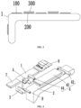
- a solar cell string production equipment which includes a rack, and a first conveying device, a second conveying device, a first carrying device 3, a transfer device 4, and a second carrying device 5 disposed on the rack.
- the first conveying device includes a first continuous conveyor belt 1 having a first horizontal section and a first side section.
- a conveying direction of the first continuous conveyor belt 1 is from the first horizontal section to the first side section.
- the second conveying device includes a second continuous conveyor belt 2 having a second horizontal section and a second side section.
- the second continuous conveyor belt 2 and the first continuous conveyor belt 1 are arranged in parallel.
- a conveying direction of the second continuous conveyor belt 2 is from the second side section to the second horizontal section.
- the angle between the first side section of the first continuous conveyor belt 1 and the first horizontal section of the first continuous conveyor belt 1 is the same as the angle between the second side section of the second continuous conveyor belt 2 and the second horizontal section of the second continuous conveyor belt 2.
- the first side section of the first continuous conveyor belt 1 and the second side section of the second continuous conveyor belt 2 are located on the same side with respect to the first horizontal section of the first continuous conveyor belt 1 and the second horizontal section of the second continuous conveyor belt 2.
- the first continuous conveyor belt 1 and the second continuous conveyor belt 2 are wound on a drive shaft distributed at a right angle or an obtuse angle to make a turn in the vertical direction.
- the first continuous conveyor belt 1 and the second continuous conveyor belt 2 are each provided with suction holes that can hold the back film 100 and the front film 200, thereby remaining stable during the conveying process.
- the first continuous conveyor belt 1 and the second continuous conveyor belt 2 form a sealed cavity inside, and a negative pressure is formed in the sealed cavity, so that the back film 100 and the front film 200 can be held on the first continuous conveyor belt 1 and the second continuous conveyor belt 2.
- the first carrying device 3 is disposed in front of the first side section of the first continuous conveyor belt 1 and the second side section of the second continuous conveyor belt 2, for carrying the back film 100 from the first side section of the first continuous conveyor belt 1 to the second side section of the second continuous conveyor belt 2.
- the first carrying device 3 includes a drive device and a suction member capable of holding the back film 100.
- the suction member may be a plate provided with a suction cup on a side wall of the plate. The plate is directly opposite the first side section and the second side section.
- the drive device can drive the suction member to reciprocate in the X direction and Y direction.
- the adsorption force of the suction member is greater than the holding force of the first continuous conveyor belt 1, so that the back film 100 can be removed from the first continuous conveyor belt 1 and placed on the second continuous conveyor belt 2.
- the suction member can be opened and closed, thereby controlling the suction member to produce the holding force.
- the X direction is parallel to the extension direction of the first horizontal section or the second horizontal section
- the Y direction is horizontally perpendicular to the X direction
- the Z direction is vertically perpendicular to the X direction.
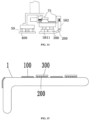
- the transfer device 4 is configured to transfer and place a pressing tool 300 from the output end of the second horizontal section to a front film 200 on the first horizontal section.
- the second carrying device 5 is located between the output end of the first horizontal section of the first continuous conveyor belt 1 and the input end of the second horizontal section of the second continuous conveyor belt 2.
- the second carrying device 5 is used to carry the front film 200 and the pressing tool 300 in stacked arrangement from the output end of the first horizontal section of the first continuous conveyor belt 1 to the input end of the second horizontal section of the second continuous conveyor belt 2.
- the second horizontal section of the second continuous conveyor belt 2 is used as a working platform for producing the solar cell strings.
- the first carrying device 3 carries the back film 100 from the first side section of the first continuous conveyor belt 1 to the second side section of the second continuous conveyor belt 2.
- the pressing tool 300 and the front film 200 are transported to the second horizontal section of the second continuous conveyor belt 2 by the second carrying device 5.
- the pressing tool 300 is transported to the output end of the second continuous conveyor belt 2, and then transferred by the transfer device 4 to the front film 200 on the first horizontal section of the first continuous conveyor belt 1. Therefore, the back film 100 and the front film 200 can be conveyed by the same conveyor line, and the pressing tool 300 can be recycled, optimizing the structure of the production equipment of the solar cell string.
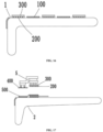
- the production equipment of the solar cell string further includes a film-supplying device 6.
- the film-supplying device 6 is provided on a side of the input end of the first horizontal section of the first continuous conveyor belt 1, for preparing and laying a film group at the input end of the first horizontal section of the first continuous conveyor belt 1.
- the film group includes the back film 100 and the front film 200.
- the number of films prepared and placed by the film-supplying device 6 each time is not limited, which can meet the needs of the production equipment of the solar cell string.
- the difference between the back film 100 and the front film 200 is merely that the back film 100 is on the back of the solar cell 400 in the solar cell string, and the front film 200 is on the front of the solar cell 400 in the solar cell string.
- the structures of the back film 100 and the front film 200 are the same, and both the back film 100 and the front film 200 are adhesive film after being heated, so the back film 100 and the front film 200 can be prepared by the film-supplying device 6 at the same time.
- the transfer device 4 includes a first gripping device 41 and a drive device.
- the first gripping device 41 is provided between the input end of the first horizontal section of the first continuous conveyor belt 1 and the output end of the second horizontal section of the second continuous conveyor belt 2.
- the first gripping device 41 can grip the pressing tool 300 from the output end of the second horizontal section of the second continuous conveyor belt 2 and stack the pressing tool 300 on the front film 200 of the input end of the first horizontal section of the first continuous conveyor belt 1.
- the drive device can drive the first gripping device 41 to implement reciprocating motion in the Y, Z direction.
- the first gripping device 41 may be a gripper or suction member, which can clamp or adsorb the pressing tool 300.
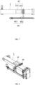
- the transfer device 4 includes a second gripping device 42, a third continuous conveyor belt 43, and a third gripping device 44.
- the second gripping device 42 is located above the output end of the second horizontal section of the second continuous conveyor belt 2.
- the third continuous conveyor belt 43 is located above the middle of the second horizontal section of the second continuous conveyor belt 2.
- the third gripping device 44 is located between the first continuous conveyor belt 1 and the third continuous conveyor belt 43.
- the conveying direction of the third continuous conveyor belt 43 is opposite to the conveying direction of the second horizontal section of the second continuous conveyor belt 2.
- the second gripping device 42 can grab the pressing tool 300 from the output end of the second horizontal section of the second continuous conveyor belt 2 and place the pressing tool 300 at the input end of the third continuous conveyor belt 43.
- the third gripping device 44 is located on a side of the output end of the third continuous conveyor belt 43, and the third gripping device 44 is located close to the second carrying device 5.
- the third gripping device 44 can grip the pressing tool 300 from the output of the third continuous conveyor belt 43 and stack the pressing tool 300 on the front film 200.
- the structure of the second gripping device 42 and the third gripping device 44 is the same as the structure of the first gripping device 41, which will not be repeated herein.
- the second gripping device 42 is connected to the drive device and is capable of reciprocating movement in the X and Z directions.
- the third gripping device 44 is connected to the drive device and can reciprocate movement in the Y and Z directions.
- the stacked pressing tool 300 and front film 200 are transmitted over a long distance through the first continuous conveyor belt 1, which is easy to misalign the pressing tool 300 and the front film 200, making it difficult for the second carrying device 5 to grip the pressing tool 300. Since the output end of the third continuous conveyor belt 43 is close to the output end of the first horizontal section of the first continuous conveyor belt 1, the distance that the pressing tool 300 is conveyed after stacked on the front film 200 can be reduced, thereby reducing the risk of misalignment between the pressing tool 300 and the front film 200.
- a limit plate 45 is provided above the output end of the third continuous conveyor belt 43.
- the limit plate 45 will block the pressing tool 300 forward.
- a buffer station of the pressing tool 300 is also provided to meet the number required for the pressing tool 300 in the production equipment of solar cell string.
- the width of the third continuous conveyor belt 43 is less than the length of the pressing tool 300, and when the pressing tool 300 is placed on the third continuous conveyor belt 43, the ends of the pressing tool 300 extend out of the third continuous conveyor belt 43.
- Lifting plates 46 are provided symmetrically on both sides of the third continuous conveyor belt 43, and the lifting plates 46 can move up and down.
- the upper surface of the lifting plates 46 is lower than the upper surface of the third continuous conveyor belt 43.
- the upper surface of the lifting plates 46 is higher than the upper surface of the third continuous conveyor belt 43.
- the lifting plate 46 and the third continuous conveyor belt 43 may be covered with the pressing tools 300. After the pressing tools 300 on the third continuous conveyor belt 43 all flow into the production line of the solar cell string, the lifting plate 46 will move down to place the pressing tools 300 thereon on the third continuous conveyor belt 43 and flow into the production line of the solar cell string.
- the projection of each of the lifting plates 46 does not coincide with a projection of the third gripping device 44 to keep clear the second carrying device 5.
- the transfer device 4 further includes a buffering mechanism 47 and a carrying mechanism 48.
- the buffering mechanism 47 is provided above the middle of the first horizontal section of the first continuous conveyor belt 1 for carrying the pressing tool 300 gripped by the third gripping device 44 from the output end of the third continuous conveyor belt 43.
- the buffering mechanism 47 includes a synchronous belt 471 and a baffle 472.
- the carrying mechanism 48 includes a power unit 481 and a manipulator 482 disposed above the first horizontal section of the first continuous conveyor belt 1, for carrying and placing the pressing tool 300 from the buffering mechanism 47 to the front film 200.
- the power unit 481 is connected to the manipulator 482 to drive the manipulator 482 such that the manipulator 482 can move up and down and reciprocate along the conveying direction of the first continuous conveyor belt 1.
- the portion of the manipulator 482 facing the first continuous conveyor belt 1 is the first suction part 4821.
- the manipulator 482 may has the same structure as the second gripping device 42 and the third gripping device 44, capable of reciprocating motion in the X and Z directions, which will not be repeated herein.
- the third gripping device 44 can grab the pressing tool 300 from the output end of the third continuous conveyor belt 43 and stack the pressing tool 300 on the front film 200.
- the third gripping device 44 can grab the pressing tool 300 and store the pressing tool 300 on the synchronous belt 471 of the buffering mechanism 47, and the baffle 472 blocks the pressing tool 300 to prevent the pressing tool 300 from falling.
- the power unit 481 of the carrying mechanism 48 drives the manipulator 482 to move and drives the first suction part 4821 to suction the pressing tool 300 on the buffering mechanism 47 and place the pressing tool 300 on the front film 200 near the output end of the first continuous conveyor belt 1.
- Such a design increases productivity and prevents the accumulation of materials.
- the production equipment further includes a first feeding device 7 for feeding the solar cell 400 and a second feeding device 8 for feeding the solder ribbon 500.
- the first feeding device 7 is located at a side of the output end of the first horizontal section of the first continuous conveyor belt 1 for providing the solar cell 400.
- the second feeding device 8 can draw the solder ribbon 500 at the input end of the second horizontal section of the second continuous conveyor belt 2 for providing the solder ribbon 500.
- the position of the first feeding device 7 near the output end of the first horizontal section of the first continuous conveyor belt 1 is the gripping station of the solar cell 400, and the solar cell 400 is provided on the gripping station.
- the second carrying device 5 can simultaneously grab the stacked pressing tool 300 and the front film 200 and the solar cell 400.
- the second carrying device 5 includes a connecting plate 51, a first gripping mechanism 58 and a second gripping mechanism 59.
- the first gripping mechanism 58 and the second gripping mechanism 59 are connected by the connecting plate 51 and are distributed at both ends of the connecting plate 51.
- the first gripping mechanism 58 grabs the stacked pressing tool 300 and the front film 200
- the second gripping mechanism 59 grabs the solar cell 400.
- the first gripping mechanism 58 includes a first suction plate 52, a slide cylinder 54, a first suction cup 55, and a second suction cup 56.
- the second gripping mechanism 59 includes a second suction plate 53 and a third suction cup 57.
- the connecting plate 51 is a Z-shaped plate.
- the first suction plate 52 and the second suction plate 53 are located at both ends of the bottom of the connecting plate 51.
- the first suction plate 52 and the connecting plate 51 are connected by the slide cylinder 54 to adjust the spacing between the first suction plate 52 and the second suction plate 53.
- the first suction cup 55 and the second suction cup 56 are located at the bottom of the first suction plate 52.
- the first suction cup 55 has two rows for adsorbing the pressing tool 300.
- the second suction cup 56 is located between two rows of first suction cups 55 for adsorbing the front film 200. After the first suction cup 55 contacts the upper surface of the pressing tool 300, the suction force can be generated to suction the pressing tool 300.
- the part of the pressing tool 300 directly opposite the second suction cup 56 is provided with a through hole, because the contact surface of the pressing tool 300 and the front film 200 is smooth, the adsorption force generated by the second suction cup 56 can lift the front film 200 through the through hole.
- the third suction cup 57 is located at the bottom of the second suction plate 53 for adsorbing the solar cell 400.
- the first gripping mechanism 58 includes a first gripper 581 and a second gripper 582.
- the first gripper 581 includes a plurality of fourth suction cups 5811.
- the plurality of fourth suction cups 5811 for holding the pressing tool 300 and the front film 200 at a bottom of the pressing tool 300.
- Difference from the second carrying device 5 in the first embodiment is that the side of the first gripper 581 is also provided with the second gripper 582.
- the second gripper 582 is provided on a side of the first gripper 581. As shown in FIG.
- the two sides of the first gripper 581 are respectively provided with the second gripper 582, the second gripper 582 is arranged parallel to the first gripper 581, and the second gripper 582 is used to hold a portion of the front film 200 beyond the edge of the pressing tool 300.
- the ways that the second gripping mechanism 59 grabs the solar cell 400 next to the front film 200 and that the plurality of fourth suction cup 5811 absorbs the pressing tool 300 and the front film 200 on the bottom of the pressing tool 300 are the same as the way in the first embodiment of the second carrying device 5, which will not be repeated herein.
- the front film 200 below the pressing tool 300 may not require the fourth suction cups 5811.
- a solar cell string production method is further provided, which is performed through the following steps using the solar cell string production equipment.
- the input end of the first horizontal section of the first continuous conveyor belt 1 is transported forward once every time the film is laid. It can be understood that every time the film is laid on the input end of the first horizontal section of the first continuous conveyor belt 1, the first continuous conveyor belt will move to the output end of the first continuous conveyor belt 1 once.
- one film is laid once at the input end of the first horizontal section of the first continuous conveyor belt 1, the first continuous conveyor belt 1 is transported forward once, and one film is transported to the output end of the first continuous conveyor belt 1 at a time.
- the first continuous conveyor belt 1 is transported forward once, and M films are transported to the output end of the first continuous conveyor belt 1, where N is a natural number greater than 1, M is a natural number less than N.
- the first continuous conveyor belt 1 is transported forward once, and N films are transported to the output end of the first continuous conveyor belt 1 at a time.
- the first continuous conveyor belt 1 is transported forward once, and one film is transported to the output end of the first continuous conveyor belt 1 at a time.
- step (S4) the pressing tool 300 is stacked on the front film 200 on the first continuous conveyor belt 1, thereby forming the stacked front film 200 and the pressing tool 300.
- step (S1) at least first three films provided by the film-supplying device 6 are used as the back films 100, and the remaining films are alternately used as the front film 200 and the back film 100, so that the production equipment of the solar cell string can continuously work.
- the transfer device 4 includes the first gripping device 41.
- the first gripping device 41 grabs and stacks the pressing tool 300 on the second front film 200 located at the input end of the first horizontal section of the first continuous conveyor belt 1.
- the transfer device 4 includes the second gripping device 42, the third continuous conveyor belt 43, and the third gripping device 44.
- the second gripping device 42 grips and places the pressing tool 300 at the input end of the third continuous conveyor belt 43.
- the pressing tool 300 is conveyed to the output end of the third continuous conveyor belt 43, and the third gripping device 44 grips and stacks the pressing tool 300 on the front film 200 near the output end of the first horizontal section of the first continuous conveyor belt 1, thereby forming the stacked front film 200 and pressing tool 300.
- the transfer device 4 further includes the buffering mechanism 47 and the carrying mechanism 48.
- the buffering mechanism 47 is located above the middle of the first horizontal section of the first continuous conveyor belt 1.
- the third gripping device 44 grips the pressing tool 300 from the output of the third continuous conveyor belt 43 and places the pressing tool 300 on the buffering mechanism 47.
- the carrying mechanism 48 includes the power unit 481 and the manipulator 482 disposed above the first horizontal section of the first continuous conveyor belt 1.
- the manipulator 482 carries the pressing tool 300 on the buffering mechanism 47 and places the pressing tool 300 on the second front film 200, thereby forming the stacked second front film 200 and the pressing tool 300.
- step (S4) the solar cell 400 and the stacked front film 200 and the pressing tool 300 are transported and placed together by the second carrying device 5.
- the second conveying device further includes a heating device 9.
- the heating device 9 is located inside the middle of the second horizontal section of the second continuous conveyor belt 2, which can heat the solar cell string from the bottom of the solar cell string.
- the heating device 9 is an electric heater. When the heating device 9 generates the heat energy to reach the solar cell string above the heating device 9, the back film 100 and the front film 200 can be heated, thereby making the back film 100 and the front film 200 viscous, and the solder ribbon 500 and the solar cell 400 will be bonded together.
Landscapes
- Engineering & Computer Science (AREA)
- Mechanical Engineering (AREA)
- Container, Conveyance, Adherence, Positioning, Of Wafer (AREA)
- Life Sciences & Earth Sciences (AREA)
- Sustainable Development (AREA)
- Sustainable Energy (AREA)
- Photovoltaic Devices (AREA)
- Specific Conveyance Elements (AREA)
Claims (13)
- Vorrichtung zur Herstellung eines Solarzellenstrangs, umfassend:eine erste Fördereinrichtung;eine zweite Fördereinrichtung;eine erste Tragevorrichtung (3);eine Transfervorrichtung (4);eine zweite Tragevorrichtung (5); undeine Filmzuführungsvorrichtung (6);eine erste Einspeisevorrichtung (7) zum Einspeisen der Solarzelle (400);eine zweite Einspeisevorrichtung (8) zum Einspeisen des Lötbandes (500);wobei die erste Fördervorrichtung ein erstes Endlosförderband (1) mit einem ersten horizontalen Abschnitt und einem ersten Seitenabschnitt umfasst; und wobei eine Förderrichtung des ersten Endlosförderbandes (1) von dem ersten horizontalen Abschnitt zu dem ersten Seitenabschnitt verläuft;wobei die zweite Fördereinrichtung ein zweites Endlosförderband (2) mit einem zweiten horizontalen Abschnitt und einem zweiten Seitenabschnitt umfasst; und wobei eine Förderrichtung des zweiten Endlosförderbandes (2) von dem zweiten Seitenabschnitt zu dem zweiten horizontalen Abschnitt verläuft;wobei das zweite Endlosförderband (2) und das erste Endlosförderband (1) parallel angeordnet sind; und der erste Seitenabschnitt und der zweite Seitenabschnitt auf der gleichen Seite in Bezug auf den ersten horizontalen Abschnitt und den zweiten horizontalen Abschnitt angeordnet sind;wobei die erste Tragevorrichtung (3) vor dem ersten Seitenabschnitt und dem zweiten Seitenabschnitt vorgesehen ist und so konfiguriert ist, dass sie einen hinteren Film (100) von dem ersten Seitenabschnitt zu dem zweiten Seitenabschnitt trägt;wobei die Transfervorrichtung (4) so konfiguriert ist, dass sie ein Presswerkzeug (300) von einem Ausgangsende des zweiten horizontalen Abschnitts zu einem vorderen Film (200) auf dem ersten horizontalen Abschnitt transferiert und platziert;wobei die zweite Tragvorrichtung (5) zwischen einem Ausgangsende des ersten horizontalen Abschnitts und einem Eingangsende des zweiten horizontalen Abschnitts vorgesehen ist; und wobei die zweite Tragevorrichtung (5) so konfiguriert ist, dass sie den vorderen Film (200) und das Presswerkzeug (300) in gestapelter Anordnung vom Ausgangsende des ersten horizontalen Abschnitts zum Eingangsende des zweiten horizontalen Abschnitts trägt;wobei die Filmzuführungsvorrichtung (6) an einer Seite eines Eingangsendes des ersten horizontalen Abschnitts vorgesehen ist und so konfiguriert ist, dass sie eine Filmgruppe am Eingangsende des ersten horizontalen Abschnitts vorbereitet und ablegt; wobei die Filmgruppe den hinteren Film (100) und den vorderen Film (200) umfasst; undwobei das erste Endlosförderband (1) und das zweite Endlosförderband (2) jeweils mit Sauglöchern zum Halten des hinteren Films (100) und des vorderen Films (200) versehen sind.
- Vorrichtung nach Anspruch 1, dadurch gekennzeichnet, dass die Transfervorrichtung (4) eine erste Greifvorrichtung (41) umfasst; wobei die erste Greifvorrichtung (41) zwischen dem Eingangsende des ersten horizontalen Abschnitts und dem Ausgangsende des zweiten horizontalen Abschnitts vorgesehen ist; und wobei die erste Greifvorrichtung (41) zum Greifen des Presswerkzeugs (300) vom Ausgangsende des zweiten horizontalen Abschnitts und zum Stapeln des Presswerkzeugs (300) auf dem vorderen Film (200) konfiguriert ist.
- Vorrichtung nach Anspruch 1, dadurch gekennzeichnet, dass die Transfervorrichtung (4) eine zweite Greifvorrichtung (42), ein drittes Endlosförderband (43) und eine dritte Greifvorrichtung (43) umfasst; die zweite Greifvorrichtung (42) oberhalb des Ausgangsendes des zweiten horizontalen Abschnitts angeordnet ist; das dritte Endlosförderband (43) oberhalb einer Mitte des zweiten horizontalen Abschnitts angeordnet ist; die dritte Greifvorrichtung (43) zwischen dem ersten Endlosförderband (1) und dem dritten Endlosförderband (43) angeordnet ist; eine Förderrichtung des dritten Endlosförderbands (43) entgegengesetzt zu einer Förderrichtung des zweiten horizontalen Abschnitts ist; die zweite Greifvorrichtung (42) zum Greifen des Presswerkzeugs (300) vom Ausgangsende des zweiten horizontalen Abschnitts und zum Platzieren des Presswerkzeugs (300) an einem Eingangsende des dritten Endlosförderbands (43) konfiguriert ist; die dritte Greifvorrichtung (44) auf einer Seite eines Ausgangsendes des dritten Endlosförderbands (43) angeordnet ist und in der Nähe der zweiten Tragevorrichtung (5) angeordnet ist; und die dritte Greifvorrichtung (44) zum Greifen des Presswerkzeugs (300) vom Ausgangsende des dritten Endlosförderbands (43) konfiguriert ist.
- Vorrichtung nach Anspruch 3, dadurch gekennzeichnet, dass die Transfervorrichtung (4) ferner einen Puffermechanismus (47) und einen Tragemechanismus (48) umfasst;der Puffermechanismus (47) oberhalb einer Mitte des ersten horizontalen Abschnitts vorgesehen ist und so konfiguriert ist, dass er das von der dritten Greifvorrichtung (44) ergriffene Presswerkzeug (300) vom Ausgangsende des dritten Endlosförderbands (43) trägt; undder Tragemechanismus (48) eine Antriebseinheit (481) und einen Manipulator (482) umfasst; der Manipulator (482) oberhalb des ersten horizontalen Abschnitts vorgesehen ist und so konfiguriert ist, dass er das Presswerkzeug (300) von dem Puffermechanismus (47) zu der vorderen Film (200) transportiert und platziert; und die Antriebseinheit (481) mit dem Manipulator (482) verbunden ist, um den Manipulator (482) anzutreiben, damit er sich auf und ab bewegt und sich entlang der Förderrichtung des ersten Endlosförderbands (1) hin- und herbewegt.
- Vorrichtung nach Anspruch 3, dadurch gekennzeichnet, dass eine Breite des dritten Endlosförderbands (43) geringer als eine Länge des Presswerkzeugs (300) ist; Hebeplatten (46) symmetrisch auf beiden Seiten des dritten Endlosförderbands (43) vorgesehen sind; die Hebeplatten (46) in der Lage sind, sich auf und ab zu bewegen; wobei in einem ersten Zustand eine obere Fläche der Hebeplatten (46) niedriger als eine obere Fläche des dritten Endlosförderbands (43) ist; in einem zweiten Zustand die obere Fläche der Hebeplatten (46) höher als die obere Fläche des dritten Endlosförderbands (43) ist; und wobei ein Vorsprung jeder der Hebeplatten (46) nicht mit einem Vorsprung der dritten Greifvorrichtung (44) zusammenfällt.
- Vorrichtung nach Anspruch 1, dadurch gekennzeichnet, dass die erste Fördereinrichtung ferner eine Heizeinrichtung (9) umfasst; und die Heizeinrichtung (9) in der Mitte des zweiten horizontalen Abschnitts angeordnet ist.
- Vorrichtung nach Anspruch 1, dadurch gekennzeichnet, dass die zweite Tragevorrichtung (5) einen ersten Greifmechanismus (58) und einen zweiten Greifmechanismus (59) umfasst;der erste Greifmechanismus (58) einen ersten Greifer (581) und einen zweiten Greifer (582) umfasst; undder erste Greifer (581) eine Vielzahl von Saugnäpfen (5811) umfasst; die Vielzahl von Saugnäpfen (5811) so konfiguriert ist, dass sie das Presswerkzeug (300) und den vorderen Film (200) an einer Unterseite des Presswerkzeugs (300) halten; der zweite Greifer (582) parallel zu dem ersten Greifer (581) angeordnet ist; der zweite Greifer (582) so konfiguriert ist, dass er einen Teil des vorderen Films (200) über eine Kante des Presswerkzeugs (300) hinaus hält; und der zweite Greifmechanismus (59) so konfiguriert ist, dass er eine Solarzelle (400) neben dem vorderen Film (200) greift.
- Verfahren zur Herstellung eines Solarzellenstrangs unter Verwendung der Vorrichtung nach Anspruch 1, umfassend:(S1) kontinuierliches Vorbereiten und Ablegen eines Films am Eingangsende des ersten horizontalen Abschnitts durch die Filmzuführungsvorrichtung (6); und Vorwärtsbefördern des Films durch das erste Endlosförderband (1), wenn der Film jedes Mal gelegt wird;(S2) nachdem der Film zum ersten Seitenabschnitt transportiert wurde, Transportieren des Films durch die erste Tragevorrichtung (3) zum zweiten Seitenabschnitt als erster hinterer Film (100); Transportieren des ersten hinteren Films (100) durch das zweite Endlosförderband (2) zum Eingangsende des zweiten horizontalen Abschnitts; und aufeinanderfolgendes Stapeln eines ersten Lötbandes (500) und einer ersten Solarzelle (400) auf dem ersten hinteren Film (100), wobei eine zweite Hälfte des ersten Lötbandes (500) auf der ersten hinteren Film (100) liegt;(S3) Fördern eines zweiten hinteren Films (100) durch das zweite Endlosförderband (2) vorwärts zum Eingangsende des zweiten horizontalen Abschnitts; und Stapeln eines zweiten Lötbandes (500) auf dem zweiten hinteren Film (100) und Ermöglichen, dass eine erste Hälfte des zweiten Lötbandes (500) auf die erste Solarzelle (400) gestapelt wird;(S4) Tragen und Platzieren eines ersten vorderen Films (200) und des Presswerkzeugs (300) durch die zweite Tragevorrichtung (5), die zusammen vom Ausgangsende des ersten horizontalen Abschnitts zur ersten Solarzelle (400) gestapelt sind; und Stapeln einer zweiten Solarzelle (400) auf einer zweiten Hälfte des zweiten Lötbandes (500); und(S5) Wiederholen der Schritte (S3) und (S4), gefolgt von Erhitzen, um den Solarzellenstrang zu erhalten, wobei, nach dem Transport durch das zweite Endlosförderband (2) zum Ausgangsende des zweiten horizontalen Abschnitts, das Presswerkzeug (300) durch die Transfervorrichtung (4) zu einen zweiten vorderen Film (200) auf dem ersten horizontalen Abschnitt zur Wiederverwendung übertragen wird.
- Verfahren nach Anspruch 8, dadurch gekennzeichnet, dass der Schritt (S4) weiterhin umfasst:
Stapeln des Presswerkzeugs (300) auf dem vorderen Film (200) auf dem ersten Endlosförderband (1). - Verfahren nach Anspruch 8, dadurch gekennzeichnet, dass in Schritt (S1) mindestens die ersten drei von den Filmen, bereitgestellten bei der Filmzuführungsvorrichtung (6), als hinteren Film (100) verwendet werden; und die verbleibenden Filme abwechselnd als vorderen Film (200) und hinteren Film (100) verwendet werden.
- Verfahren nach Anspruch 9, dadurch gekennzeichnet, dass in Schritt (S5) die Transfervorrichtung (4) eine erste Greifvorrichtung (41) umfasst; und das Presswerkzeug (300) von der ersten Greifvorrichtung (41) ergriffen und auf dem zweiten vorderen Film (200) am Eingangsende des ersten horizontalen Abschnitts gestapelt wird.
- Verfahren nach Anspruch 9, dadurch gekennzeichnet, dass in Schritt (S5) die Transfervorrichtung (4) eine zweite Greifvorrichtung (42), ein drittes Endlosförderband (43) und eine dritte Greifvorrichtung (44) umfasst; die zweite Greifvorrichtung (42) so konfiguriert ist, dass sie das Presswerkzeug (300) an einem Eingangsende des dritten Endlosförderbandes (43) greift und platziert; das Presswerkzeug (300) zu einem Ausgangsende des dritten Endlosförderbandes (43) befördert wird; und die dritte Greifvorrichtung (44) so konfiguriert ist, dass sie das Presswerkzeug (300) auf den zweiten vorderen Film (200) in der Nähe des Ausgangsendes des ersten horizontalen Abschnitts greift und stapelt.
- Verfahren nach Anspruch 12, dadurch gekennzeichnet, dass in Schritt (S5) die Transfervorrichtung (4) ferner einen Puffermechanismus (47) und einen Tragemechanismus (48) umfasst;wobei sich der Puffermechanismus (47) oberhalb einer Mitte des ersten horizontalen Abschnitts befindet;die dritte Greifvorrichtung (44) das Presswerkzeug (300) vom Ausgangsende des dritten Endlosförderbandes (43) zum Puffermechanismus (47) greift und platziert; undder Tragemechanismus (48) eine Antriebseinheit (481) und einen Manipulator (482) umfasst; wobei der Manipulator (482) über dem ersten horizontalen Abschnitt sich befindet und der Manipulator (48) das Presswerkzeug (300) auf dem Puffermechanismus (47) zum zweiten vorderen Film (200) trägt.
Applications Claiming Priority (4)
| Application Number | Priority Date | Filing Date | Title |
|---|---|---|---|
| CN202222438089.2U CN218482214U (zh) | 2022-09-15 | 2022-09-15 | 一种多功能抓手及电池串铺设设备 |
| CN202211126312.8A CN115206858B (zh) | 2022-09-16 | 2022-09-16 | 一种电池串生产设备及生产方法 |
| CN202223234612.6U CN219085948U (zh) | 2022-12-05 | 2022-12-05 | 一种膜片传输线和电池串生产设备 |
| PCT/CN2023/088169 WO2023151705A1 (zh) | 2022-09-15 | 2023-04-13 | 一种电池串生产设备及生产方法 |
Publications (4)
| Publication Number | Publication Date |
|---|---|
| EP4258331A1 EP4258331A1 (de) | 2023-10-11 |
| EP4258331A4 EP4258331A4 (de) | 2024-05-29 |
| EP4258331C0 EP4258331C0 (de) | 2025-01-22 |
| EP4258331B1 true EP4258331B1 (de) | 2025-01-22 |
Family
ID=87563713
Family Applications (1)
| Application Number | Title | Priority Date | Filing Date |
|---|---|---|---|
| EP23733611.0A Active EP4258331B1 (de) | 2022-09-15 | 2023-04-13 | Vorrichtung und verfahren zur herstellung eines batteriestrangs |
Country Status (4)
| Country | Link |
|---|---|
| US (1) | US11973156B2 (de) |
| EP (1) | EP4258331B1 (de) |
| KR (1) | KR102582959B1 (de) |
| WO (1) | WO2023151705A1 (de) |
Families Citing this family (3)
| Publication number | Priority date | Publication date | Assignee | Title |
|---|---|---|---|---|
| CN115295685B (zh) * | 2022-10-09 | 2022-12-16 | 苏州小牛自动化设备有限公司 | 固连电池串的方法、压具组件及固化装置 |
| CN118559053B (zh) * | 2024-08-01 | 2024-10-11 | 四川鑫跃鑫科学仪器有限公司 | 金属管道车削装置 |
| CN119347265A (zh) * | 2024-11-01 | 2025-01-24 | 合肥合孚智慧能源有限公司 | 一种储能电池箱装配用焊接夹持工装 |
Family Cites Families (21)
| Publication number | Priority date | Publication date | Assignee | Title |
|---|---|---|---|---|
| WO2003059570A1 (en) * | 2002-01-04 | 2003-07-24 | G.T. Equipment Technologies Inc. | Solar cell stringing machine |
| DE102006007447A1 (de) * | 2005-12-30 | 2007-07-12 | Teamtechnik Maschinen Und Anlagen Gmbh | Solarzellen-Verbindungsvorrichtung, Streifen-Niederhaltevorrichtung und Transportvorrichtung für eine Solarzellen-Verbindungsvorrichtung |
| DE102008025764A1 (de) * | 2007-05-29 | 2008-12-18 | Reis Gmbh & Co. Kg Maschinenfabrik | Solarzellen-Fertigungsanlage |
| EP2299501A1 (de) * | 2009-09-16 | 2011-03-23 | 3S Industries AG | Verfahren und Vorrichtung zur Ausstattung einer Solarzelle mit einem Lötband |
| DE102010045098A1 (de) * | 2010-09-13 | 2012-03-15 | Rena Gmbh | Vorrichtung und Verfahren zum Vereinzeln und Transportieren von Substraten |
| US8561878B2 (en) * | 2010-09-27 | 2013-10-22 | Banyan Energy, Inc. | Linear cell stringing |
| US20130272833A1 (en) * | 2012-04-16 | 2013-10-17 | Komax Holding Ag | Solar cell string layup system and method |
| EP2704213A1 (de) * | 2012-08-30 | 2014-03-05 | Komax Holding AG | Verfahren und Vorrichtung zum Verbinden von Solarzellen zu einem Solarzellen-String sowie Solarzellen-String |
| US8748212B2 (en) * | 2012-08-31 | 2014-06-10 | Komax Holding Ag | Method and device for producing solar cell strings |
| US20200202404A1 (en) * | 2016-06-01 | 2020-06-25 | Solaero Technologies Corp. | Automated assembly and mounting of solar cells on space panels |
| US10507991B2 (en) * | 2018-05-08 | 2019-12-17 | Applied Materials, Inc. | Vacuum conveyor substrate loading module |
| CN210015865U (zh) * | 2019-07-19 | 2020-02-04 | 无锡奥特维科技股份有限公司 | 叠瓦电池串生产设备 |
| CN110911522B (zh) | 2019-10-14 | 2025-01-17 | 营口金辰机械股份有限公司 | 一种高速光伏组件生产设备及其工艺方法 |
| CN111403553B (zh) * | 2020-03-26 | 2024-10-25 | 无锡奥特维科技股份有限公司 | 叠放设备 |
| CN112289889A (zh) * | 2020-10-20 | 2021-01-29 | 无锡奥特维科技股份有限公司 | 电池串生产方法 |
| CN112490333B (zh) * | 2020-12-18 | 2025-05-27 | 无锡奥特维科技股份有限公司 | 电池串生产线及电池串生产设备 |
| CN115548160B (zh) * | 2021-06-30 | 2025-08-05 | 晶科能源股份有限公司 | 光伏电池串返修装置及维修方法 |
| CN114744080B (zh) * | 2022-06-10 | 2022-10-21 | 苏州小牛自动化设备有限公司 | 一种电池串生产方法及电池串铺设设备 |
| CN114833504B (zh) * | 2022-07-05 | 2022-11-25 | 江苏小牛自动化设备有限公司 | 一种电池串制备方法及电池串焊接设备 |
| CN115206858B (zh) * | 2022-09-16 | 2022-12-06 | 苏州小牛自动化设备有限公司 | 一种电池串生产设备及生产方法 |
| CN115207165B (zh) * | 2022-09-15 | 2022-12-16 | 苏州小牛自动化设备有限公司 | 吸附单元、传输机构、上料装置及电池串铺设方法 |
-
2023
- 2023-04-13 KR KR1020237022931A patent/KR102582959B1/ko active Active
- 2023-04-13 WO PCT/CN2023/088169 patent/WO2023151705A1/zh not_active Ceased
- 2023-04-13 EP EP23733611.0A patent/EP4258331B1/de active Active
- 2023-06-28 US US18/343,237 patent/US11973156B2/en active Active
Also Published As
| Publication number | Publication date |
|---|---|
| EP4258331A4 (de) | 2024-05-29 |
| EP4258331C0 (de) | 2025-01-22 |
| US11973156B2 (en) | 2024-04-30 |
| WO2023151705A1 (zh) | 2023-08-17 |
| EP4258331A1 (de) | 2023-10-11 |
| KR102582959B1 (ko) | 2023-09-25 |
| US20230361233A1 (en) | 2023-11-09 |
Similar Documents
| Publication | Publication Date | Title |
|---|---|---|
| EP4258331B1 (de) | Vorrichtung und verfahren zur herstellung eines batteriestrangs | |
| KR102692435B1 (ko) | 전지 스트링 제조방법 및 장치 | |
| CN205992538U (zh) | 搭接装置 | |
| CN115206858B (zh) | 一种电池串生产设备及生产方法 | |
| CN109590644B (zh) | 工装铺设方法、装置以及串焊机 | |
| CN105895733B (zh) | 太阳能电池串全自动叠焊机 | |
| CN114212513B (zh) | 光伏接线盒传送装置和输送系统 | |
| CN111403529B (zh) | 电池串叠放设备及电池串叠放方法 | |
| CN111697106A (zh) | 电池串制备装置及串焊设备 | |
| CN111564526A (zh) | 焊带铺设装置、叠放设备及叠放方法 | |
| CN112490331B (zh) | 抓取单元、抓取装置、电池串叠放设备及电池串叠放方法 | |
| CN112490333A (zh) | 电池串生产线及电池串生产设备 | |
| CN114871764A (zh) | 一种电池串焊接设备及焊接方法 | |
| CN115377251B (zh) | 一种覆膜电池串生产设备 | |
| CN111403553A (zh) | 叠放设备 | |
| CN117697238A (zh) | 串接系统、串接方法及阵列焊机 | |
| CN110695428A (zh) | 焊带处理装置及电池片串焊设备 | |
| CN115295685B (zh) | 固连电池串的方法、压具组件及固化装置 | |
| CN217534182U (zh) | 一种预热装置 | |
| CN217371331U (zh) | 一种电池串焊接设备 | |
| CN108987321B (zh) | 治具循环输送装置及方法 | |
| CN211578768U (zh) | 电池串叠放设备 | |
| CN214086597U (zh) | 一种多层载板搬运系统及太阳能电池生产线 | |
| CN215103541U (zh) | 一种等离子体增强化学气相沉积设备 | |
| CN212085032U (zh) | 焊带铺设装置及叠放设备 |
Legal Events
| Date | Code | Title | Description |
|---|---|---|---|
| STAA | Information on the status of an ep patent application or granted ep patent |
Free format text: STATUS: UNKNOWN |
|
| STAA | Information on the status of an ep patent application or granted ep patent |
Free format text: STATUS: THE INTERNATIONAL PUBLICATION HAS BEEN MADE |
|
| PUAI | Public reference made under article 153(3) epc to a published international application that has entered the european phase |
Free format text: ORIGINAL CODE: 0009012 |
|
| STAA | Information on the status of an ep patent application or granted ep patent |
Free format text: STATUS: REQUEST FOR EXAMINATION WAS MADE |
|
| 17P | Request for examination filed |
Effective date: 20230703 |
|
| AK | Designated contracting states |
Kind code of ref document: A1 Designated state(s): AL AT BE BG CH CY CZ DE DK EE ES FI FR GB GR HR HU IE IS IT LI LT LU LV MC ME MK MT NL NO PL PT RO RS SE SI SK SM TR |
|
| A4 | Supplementary search report drawn up and despatched |
Effective date: 20240425 |
|
| RIC1 | Information provided on ipc code assigned before grant |
Ipc: H01L 31/18 20060101ALI20240419BHEP Ipc: H01L 21/677 20060101AFI20240419BHEP |
|
| REG | Reference to a national code |
Ref country code: DE Ref legal event code: R079 Free format text: PREVIOUS MAIN CLASS: H01L0021677000 Ipc: H01L0031050000 Ref document number: 602023001789 Country of ref document: DE |
|
| GRAP | Despatch of communication of intention to grant a patent |
Free format text: ORIGINAL CODE: EPIDOSNIGR1 |
|
| STAA | Information on the status of an ep patent application or granted ep patent |
Free format text: STATUS: GRANT OF PATENT IS INTENDED |
|
| RIC1 | Information provided on ipc code assigned before grant |
Ipc: H01L 21/677 20060101ALI20240906BHEP Ipc: H01L 31/18 20060101ALI20240906BHEP Ipc: H01L 31/05 20140101AFI20240906BHEP |
|
| INTG | Intention to grant announced |
Effective date: 20240918 |
|
| GRAS | Grant fee paid |
Free format text: ORIGINAL CODE: EPIDOSNIGR3 |
|
| GRAA | (expected) grant |
Free format text: ORIGINAL CODE: 0009210 |
|
| STAA | Information on the status of an ep patent application or granted ep patent |
Free format text: STATUS: THE PATENT HAS BEEN GRANTED |
|
| DAV | Request for validation of the european patent (deleted) | ||
| DAX | Request for extension of the european patent (deleted) | ||
| AK | Designated contracting states |
Kind code of ref document: B1 Designated state(s): AL AT BE BG CH CY CZ DE DK EE ES FI FR GB GR HR HU IE IS IT LI LT LU LV MC ME MK MT NL NO PL PT RO RS SE SI SK SM TR |
|
| REG | Reference to a national code |
Ref country code: GB Ref legal event code: FG4D |
|
| REG | Reference to a national code |
Ref country code: CH Ref legal event code: EP |
|
| REG | Reference to a national code |
Ref country code: IE Ref legal event code: FG4D |
|
| REG | Reference to a national code |
Ref country code: DE Ref legal event code: R096 Ref document number: 602023001789 Country of ref document: DE |
|
| U01 | Request for unitary effect filed |
Effective date: 20250124 |
|
| U07 | Unitary effect registered |
Designated state(s): AT BE BG DE DK EE FI FR IT LT LU LV MT NL PT RO SE SI Effective date: 20250131 |
|
| U20 | Renewal fee for the european patent with unitary effect paid |
Year of fee payment: 3 Effective date: 20250409 |
|
| PG25 | Lapsed in a contracting state [announced via postgrant information from national office to epo] |
Ref country code: RS Free format text: LAPSE BECAUSE OF FAILURE TO SUBMIT A TRANSLATION OF THE DESCRIPTION OR TO PAY THE FEE WITHIN THE PRESCRIBED TIME-LIMIT Effective date: 20250422 |
|
| PG25 | Lapsed in a contracting state [announced via postgrant information from national office to epo] |
Ref country code: PL Free format text: LAPSE BECAUSE OF FAILURE TO SUBMIT A TRANSLATION OF THE DESCRIPTION OR TO PAY THE FEE WITHIN THE PRESCRIBED TIME-LIMIT Effective date: 20250122 |
|
| PG25 | Lapsed in a contracting state [announced via postgrant information from national office to epo] |
Ref country code: ES Free format text: LAPSE BECAUSE OF FAILURE TO SUBMIT A TRANSLATION OF THE DESCRIPTION OR TO PAY THE FEE WITHIN THE PRESCRIBED TIME-LIMIT Effective date: 20250122 |
|
| PG25 | Lapsed in a contracting state [announced via postgrant information from national office to epo] |
Ref country code: IS Free format text: LAPSE BECAUSE OF FAILURE TO SUBMIT A TRANSLATION OF THE DESCRIPTION OR TO PAY THE FEE WITHIN THE PRESCRIBED TIME-LIMIT Effective date: 20250522 Ref country code: NO Free format text: LAPSE BECAUSE OF FAILURE TO SUBMIT A TRANSLATION OF THE DESCRIPTION OR TO PAY THE FEE WITHIN THE PRESCRIBED TIME-LIMIT Effective date: 20250422 |
|
| PG25 | Lapsed in a contracting state [announced via postgrant information from national office to epo] |
Ref country code: HR Free format text: LAPSE BECAUSE OF FAILURE TO SUBMIT A TRANSLATION OF THE DESCRIPTION OR TO PAY THE FEE WITHIN THE PRESCRIBED TIME-LIMIT Effective date: 20250122 |
|
| PG25 | Lapsed in a contracting state [announced via postgrant information from national office to epo] |
Ref country code: GR Free format text: LAPSE BECAUSE OF FAILURE TO SUBMIT A TRANSLATION OF THE DESCRIPTION OR TO PAY THE FEE WITHIN THE PRESCRIBED TIME-LIMIT Effective date: 20250423 |
|
| PGFP | Annual fee paid to national office [announced via postgrant information from national office to epo] |
Ref country code: TR Payment date: 20250408 Year of fee payment: 3 |
|
| PG25 | Lapsed in a contracting state [announced via postgrant information from national office to epo] |
Ref country code: SM Free format text: LAPSE BECAUSE OF FAILURE TO SUBMIT A TRANSLATION OF THE DESCRIPTION OR TO PAY THE FEE WITHIN THE PRESCRIBED TIME-LIMIT Effective date: 20250122 |
|
| PG25 | Lapsed in a contracting state [announced via postgrant information from national office to epo] |
Ref country code: CZ Free format text: LAPSE BECAUSE OF FAILURE TO SUBMIT A TRANSLATION OF THE DESCRIPTION OR TO PAY THE FEE WITHIN THE PRESCRIBED TIME-LIMIT Effective date: 20250122 |
|
| PG25 | Lapsed in a contracting state [announced via postgrant information from national office to epo] |
Ref country code: SK Free format text: LAPSE BECAUSE OF FAILURE TO SUBMIT A TRANSLATION OF THE DESCRIPTION OR TO PAY THE FEE WITHIN THE PRESCRIBED TIME-LIMIT Effective date: 20250122 |
|
| PLBE | No opposition filed within time limit |
Free format text: ORIGINAL CODE: 0009261 |
|
| STAA | Information on the status of an ep patent application or granted ep patent |
Free format text: STATUS: NO OPPOSITION FILED WITHIN TIME LIMIT |
|
| PG25 | Lapsed in a contracting state [announced via postgrant information from national office to epo] |
Ref country code: MC Free format text: LAPSE BECAUSE OF FAILURE TO SUBMIT A TRANSLATION OF THE DESCRIPTION OR TO PAY THE FEE WITHIN THE PRESCRIBED TIME-LIMIT Effective date: 20250122 |
|
| 26N | No opposition filed |
Effective date: 20251023 |