EP4257929B1 - Physical quantity measurement system and/or position measurement with bistable magnetic wire, method of measurement - Google Patents
Physical quantity measurement system and/or position measurement with bistable magnetic wire, method of measurement Download PDFInfo
- Publication number
- EP4257929B1 EP4257929B1 EP22166892.4A EP22166892A EP4257929B1 EP 4257929 B1 EP4257929 B1 EP 4257929B1 EP 22166892 A EP22166892 A EP 22166892A EP 4257929 B1 EP4257929 B1 EP 4257929B1
- Authority
- EP
- European Patent Office
- Prior art keywords
- magnetic wire
- bistable magnetic
- measurement
- bistable
- physical quantity
- Prior art date
- Legal status (The legal status is an assumption and is not a legal conclusion. Google has not performed a legal analysis and makes no representation as to the accuracy of the status listed.)
- Active
Links
Images


Classifications
-
- G—PHYSICS
- G01—MEASURING; TESTING
- G01D—MEASURING NOT SPECIALLY ADAPTED FOR A SPECIFIC VARIABLE; ARRANGEMENTS FOR MEASURING TWO OR MORE VARIABLES NOT COVERED IN A SINGLE OTHER SUBCLASS; TARIFF METERING APPARATUS; MEASURING OR TESTING NOT OTHERWISE PROVIDED FOR
- G01D5/00—Mechanical means for transferring the output of a sensing member; Means for converting the output of a sensing member to another variable where the form or nature of the sensing member does not constrain the means for converting; Transducers not specially adapted for a specific variable
- G01D5/12—Mechanical means for transferring the output of a sensing member; Means for converting the output of a sensing member to another variable where the form or nature of the sensing member does not constrain the means for converting; Transducers not specially adapted for a specific variable using electric or magnetic means
- G01D5/14—Mechanical means for transferring the output of a sensing member; Means for converting the output of a sensing member to another variable where the form or nature of the sensing member does not constrain the means for converting; Transducers not specially adapted for a specific variable using electric or magnetic means influencing the magnitude of a current or voltage
- G01D5/142—Mechanical means for transferring the output of a sensing member; Means for converting the output of a sensing member to another variable where the form or nature of the sensing member does not constrain the means for converting; Transducers not specially adapted for a specific variable using electric or magnetic means influencing the magnitude of a current or voltage using Hall-effect devices
- G01D5/147—Mechanical means for transferring the output of a sensing member; Means for converting the output of a sensing member to another variable where the form or nature of the sensing member does not constrain the means for converting; Transducers not specially adapted for a specific variable using electric or magnetic means influencing the magnitude of a current or voltage using Hall-effect devices influenced by the movement of a third element, the position of Hall device and the source of magnetic field being fixed in respect to each other
-
- G—PHYSICS
- G01—MEASURING; TESTING
- G01D—MEASURING NOT SPECIALLY ADAPTED FOR A SPECIFIC VARIABLE; ARRANGEMENTS FOR MEASURING TWO OR MORE VARIABLES NOT COVERED IN A SINGLE OTHER SUBCLASS; TARIFF METERING APPARATUS; MEASURING OR TESTING NOT OTHERWISE PROVIDED FOR
- G01D5/00—Mechanical means for transferring the output of a sensing member; Means for converting the output of a sensing member to another variable where the form or nature of the sensing member does not constrain the means for converting; Transducers not specially adapted for a specific variable
- G01D5/12—Mechanical means for transferring the output of a sensing member; Means for converting the output of a sensing member to another variable where the form or nature of the sensing member does not constrain the means for converting; Transducers not specially adapted for a specific variable using electric or magnetic means
- G01D5/14—Mechanical means for transferring the output of a sensing member; Means for converting the output of a sensing member to another variable where the form or nature of the sensing member does not constrain the means for converting; Transducers not specially adapted for a specific variable using electric or magnetic means influencing the magnitude of a current or voltage
- G01D5/20—Mechanical means for transferring the output of a sensing member; Means for converting the output of a sensing member to another variable where the form or nature of the sensing member does not constrain the means for converting; Transducers not specially adapted for a specific variable using electric or magnetic means influencing the magnitude of a current or voltage by varying inductance, e.g. by a movable armature
-
- G—PHYSICS
- G01—MEASURING; TESTING
- G01B—MEASURING LENGTH, THICKNESS OR SIMILAR LINEAR DIMENSIONS; MEASURING ANGLES; MEASURING AREAS; MEASURING IRREGULARITIES OF SURFACES OR CONTOURS
- G01B7/00—Measuring arrangements characterised by the use of electric or magnetic techniques
- G01B7/003—Measuring arrangements characterised by the use of electric or magnetic techniques for measuring position, not involving coordinate determination
-
- G—PHYSICS
- G01—MEASURING; TESTING
- G01P—MEASURING LINEAR OR ANGULAR SPEED, ACCELERATION, DECELERATION, OR SHOCK; INDICATING PRESENCE, ABSENCE, OR DIRECTION, OF MOVEMENT
- G01P3/00—Measuring linear or angular speed; Measuring differences of linear or angular speeds
- G01P3/42—Devices characterised by the use of electric or magnetic means
- G01P3/44—Devices characterised by the use of electric or magnetic means for measuring angular speed
- G01P3/48—Devices characterised by the use of electric or magnetic means for measuring angular speed by measuring frequency of generated current or voltage
- G01P3/481—Devices characterised by the use of electric or magnetic means for measuring angular speed by measuring frequency of generated current or voltage of pulse signals
- G01P3/4815—Devices characterised by the use of electric or magnetic means for measuring angular speed by measuring frequency of generated current or voltage of pulse signals using a pulse wire sensor, e.g. Wiegand wire
Definitions
- the invention relates to a composition of excitation element and a bistable magnetic wire, where a composition is prepared for measuring of various physical quantities and/or for position measurement of the bistable magnetic wire.
- the novelty of the system and method lies mainly in the specific asymmetrical position of a magnetic field of the excitation element and the actually bistable magnetic wire, thanks to which the interpretive value of the raw measured data is significantly improved.
- bistable magnetic elements are used for measurement various physical quantities and position, where the bistable magnetic element is formed by a passive member which by its magnetization reacts to a change in position in the magnetic field or to a change in a physical quantity.
- bistable magnetic properties An alloy with bistable magnetic properties and a micro wire from this alloy is described, for example, in document GB2374084A .
- the micro wire is able to respond to various physical quantities, but response evaluation is problematic, because prior art bistable magnetic elements can have complex magnetic acts where the magnetization occurs in a multiple domains within a single micro wire, not a single wall jump.
- Applications of bistable magnetic wires in position measurement, angular measurement and revolution measurement are also known.
- DE2817169A1 , DE3427582A1 , SU1753425A1 describe systems with a Wiegand wire having a certain level of magnetic bistability, wherein these systems serve to determine the approximation of a bistable magnetic element to a sensor. Due to this arrangement, it is not possible for measurement the values of physical quantities in the vicinity of the bistable magnetic element.
- the position sensor or rotation sensor according to publication EP0484716A1 uses the Wiegand wire to which rotating permanent magnets approach. The sensor responds only to changes of the magnetic field, it does not evaluate the size of physical quantities.
- the Wiegand sensor according to document DE4107847C1 allows to contactlessly transfer the information about closure of the switch, which can react to the change in a physical quantity such as temperature, pressure, acceleration, but it requires an appropriate sensor by which subsequently the switch is controlled, i. e. the physical quantity is not measured by the bistable magnetic element itself.
- Publication GB2071336A describes a magnetic induction-type position encoder and displacement detector contains two electrical windings and a bistable magnetic element, such as a Wiegand wire, which couples these two windings magnetically.
- the periodic change in polarity induces in the second winding a periodic train of electrical voltage pulses, the phase of which relative to the exciter signal can be influenced in relation to position by moving permanent magnets closer to or further away from the bistable magnetic element.
- bistable magnetic element itself has to react to the changes in the measured physical quantity and also generate a response, which is contactlessly transmitted to the receiving element.
- first and second in this document are used to name two ends differently, and these are interchangeable, thus the terms first and second does not express the superiority or importance of the respective end of the bistable magnetic wire.
- the different magnetic field at the ends in given moment of excitation leads to an asymmetric magnetic field, which, together with magnetization by a single Barkhausen jump, leads to repeatable interpretable measurement results.
- it is important that the behavior of the bistable magnetic wire is influenced fundamentally by the measured quantity or measured position, and that other factors, including acts of more complex magnetic properties of the bistable magnetic wire, were negligible or at least identifiable in a way that allows correction when evaluating raw data.
- a difference of 5 %, preferably 10 %, especially preferably more than 25 % in the values of the magnetic field at the first end and at the second end is sufficient. This contributes to the magnetization taking place in one jump within the entire wire from one end to the other. If the magnetization took place within a number of separate domains along the length of the wire, the measured response would include a number of individual acts, which significantly impairs the interpretability of the measurement. It is not possible to subsequently identify the dependence of the measured data, which reduces the application possibilities of the bistable magnetic wire.
- the aim of this invention is to achieve effective, thus complete, real bistability of magnetization, where the domain structure of the bistable magnetic wire does not consist of many domains, which would otherwise lead to magnetization by movement of multiple domains within a single wire.
- the measurement of a bistable magnetic wire with multiple domains along its length can be compared to the measurement of several separate bistable magnetic wires in a single excitation field, what causes that the resulting measurement is a sum of individual responses that cannot be reliably identified and the summary response vector is therefore practically unusable.
- the measurement of changes in the magnetic field allows to detect a change in position, a change in the rotation of the bistable magnetic wire or the carrier on which the bistable magnetic wire is mounted, and also allows to measure the relative position with respect to another object carrying the excitation element.
- position sensors rotation sensors, end sensors, sensors of proximity of a magnetic object or carrier with a magnetic object, sensors of absolute position with respect to earth's magnetic field, and the like.
- the antenna of the excitation element may be used for measurement the response, or preferably the system comprises a separate receiving element, for example in the form of a receiving coil.
- the excitation element may be a primary coil, and the receiving element will be formed by a secondary coil.
- the secondary coil can be connected to an amplifier and an evaluation unit.
- the receiving element may be located coaxially with the position of the bistable magnetic wire or may be in another position mutual to each other so as to be within range to allow for response to be received.
- the bistable magnetic wire is in the form of a micro wire with a diameter less than 50 ⁇ m, preferably less than 25 ⁇ m, especially preferably less than 15 ⁇ m. It is precisely at core diameters less than 15 ⁇ m and with suitable composition of the amorphous metal alloy, the radial magnetic structure disappears, which is related to the process of wire drawing with simultaneous rapid cooling, usually water cooling. Thanks to that the bistable magnetic wire behaves as fully bistable, thus effectively bistable over the entire length of the wire, and the domain wall during magnetization runs from the first end to the second end, not separately within several individual zones along the length of the wire. It has also been found suitable if the length of the bistable magnetic wire is at least 100 times, preferably at least 10000 times larger than the diameter of the bistable magnetic wire, which implies that it will be a small diameter wire, which we can also call micro wire.
- a typical construction of the bistable magnetic wire includes an amorphous metal core and a cover, for example glass cover, whose outer diameter is no larger than three times the diameter of the metal core.
- the thickness of the glass cover can range 1 to 20 ⁇ m.
- the glass cover, glass surface layer protects the metal core from electrical contact with the environment, from aggressive chemical environment, thanks to which the bistable magnetic wire can be used very universally, for example directly in the electric motor windings or inside of building materials, inside of human body and the like.
- a magnetic excitation with a triangle-shaped amplitude waveform which simplifies the evaluation of measured signal as described in older publications of the authors of this invention, has proven to be suitable.
- the system according to this invention is adjusted to be connected to a power element, a control element and an evaluation element.
- the power element transmits to the excitation element a power supply regulated to obtain an excitation signal of triangle-shaped amplitude waveform.
- the evaluation element acquires and analyzes the response received from the bistable magnetic wire.
- the asymmetry of the excitation field can be achieved in such a way that the excitation element, which induces a substantially symmetrical field, is arranged relatively asymmetrically with respect to the bistable magnetic wire.
- positional asymmetry ensures that the first end of the bistable magnetic wire is in a higher magnetic field than the second end, and therefore the bistable magnetic wire will be magnetized always with movement of one domain wall, the one which is in the higher field.
- Positional asymmetry can be achieved by setting a spatial relationship.
- the coil of the excitation element and the bistable magnetic wire can be arranged coaxially, thus with identical or parallel-oriented longitudinal axes.
- the asymmetry of the excitated magnetic field can be ensured by the construction of the excitation element with an uneven coil winding, for example with different thread pitches or with different number of threads at the first end or at the second end.
- the result of such a construction of the excitation element is a different amplitude of the magnetic field at the ends of the excitation element, or at a certain distance from these ends.
- the mutual position of the excitation element and the bistable magnetic wire may be spatially symmetrical, but at the first end and at the second end of the bistable magnetic wire, it will be in a magnetic field of different amplitude.
- the definition describing the mutual position of the excitation element and the bistable magnetic wire according to the first claim also includes a symmetrical mutual position if an asymmetrical magnetic field is generated by the excitation element.
- the definition of the first claim expresses a mutual arrangement, which can be achieved by several means, or by a different combination of technical means and relative spatial arrangement.
- the asymmetry of the magnetic field important to achieving the effects according to this invention is always understood in the relative relationship of the amplitudes of the magnetic field at the first end and at the second end.
- the asymmetry of the excited magnetic field can also be achieved by adding a shielding element or by placing another, secondary coil to the primary coil to the primary coil of the excitation element. In such a case, the mutual position of the excitation element and the bistable magnetic wire may also appear to be spatially symmetrical, but the asymmetry of the magnetic field at the first end and at the second end will be important.
- the excitation element can be placed coaxially with the position of the bistable magnetic wire or can be placed next to the bistable magnetic wire.
- the longitudinal axis of the magnetic field generated by the excitation element will be essentially parallel to the longitudinal axis of the bistable magnetic wire, but in principle an angularly different position is also possible, for example, the longitudinal axis of the excitation element deviates from the longitudinal axis of the bistable magnetic wire within 30 degrees.
- the magnetic field has a triangle-shaped amplitude waveform, especially preferably a symmetrical triangle-shaped amplitude waveform, and the time of the local maximum and the time of the local minimum of response of the bistable magnetic wire are evaluated, which are essentially the time points of magnetization of the bistable magnetic wire.
- the sum of these times is a parameter that expresses the dependence of the measured quantity or position, wherein other unmeasured factors and noise are suppressed. This improves the interpretability of the measured data and also accelerates their evaluation. It is also suitable if the difference between these times is calculated and this parameter expresses the parasitic magnetic field, which interferes the measurement of conventional magnetic sensors.
- the process according to this invention suppresses the effects of the parasitic magnetic field.
- An important feature of both the system and the method according to this invention is the fact that in the evaluation of the response signal, the local maximums and minimums are searched, and after their recognition, we work with times T1, T2, at which these maximums and minimums were measured. Furthermore, the method does not work on the basis of the values of the measured amplitudes, as was common in the prior art, but works with the values of the times, which is an easily and clearly identifiable parameter in the received signals. Thanks to that evaluation fast, accurate and insensitive to various secondary effects. For example, the exact position, shape and size of the excitation and sensing elements are not important.
- the method according to this invention comprises the step of exciting the magnetic field with a different or varying frequency according to the type of measured quantity or position.
- the universal excitation generator as well as the excitation element will optionally be adapted to this, or various excitation elements will be used for various applications.
- one construction of the bistable magnetic wire can also be used at different frequencies.
- the stable frequency value for one application may differ from the stable frequency used in another application, or these frequencies may be variable in a range different for the particular type of measurement.
- a significant advantage of the present invention is the repeatable accuracy of the measurements, which is related to the increase of the interpretation level of the obtained raw data. A rapid response to a change in the measured physical quantity was also demonstrated. Thanks to the small dimensions of the bistable magnetic wire, the low cost and its energetic passivity, the system according to this invention can be used in a wide range of technical applications.
- the bistable magnetic wire 1 is used for measurement the tension, or the pressure in the steel part.
- the tear pattern has a calibrated center zone and two clamping ends.
- a micro wire with a metal core diameter of approx. 15 ⁇ m and with glass cover with a total diameter of approx. 45 ⁇ m with a length of approximately 3 cm are glued to the surface in the central zone.
- the bistable magnetic wire 1 is oriented in the direction of the tension force, wherein the elongations of the steel material are transmitted to the deformation of the bistable magnetic wire 1. Slight mounting angular position deviations do not have a significant effect on the measurement accuracy.
- the bistable magnetic wire 1 is at the same time essentially aligned in a straight line, where the first end 11 and the second end 12 are in a mutual opposite position, so that the bistable magnetic wire 1 is not wound on the core, as known from prior art applications.
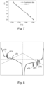
- the excitation element 2 is placed next to the bistable magnetic wire 1, the longitudinal axis of the excitation element 2 is essentially parallel to the longitudinal axis of the bistable magnetic wire 1, wherein the center of the coil of the excitation element 2 is moved with respect to the center of the bistable magnetic wire 1 by the value X recorded in figure 6 .
- the longitudinal axis of the excitation element 2 and the longitudinal axis of the bistable magnetic wire 1 are placed in a position, where if we intersect one common plain through them, this common plain is essentially perpendicular to the surface of the steel part.
- the measuring system is insensitive to the inaccuracies of the placement of the individual elements, it is only essential, that the elongations of the measured material are reliably transferred to the bistable magnetic wire 1.
- the positional asymmetry of the excitation element 2 leads to the desired difference of the magnetic field at the first end 11 and at the second end 12, which together with the properties of the bistable magnetic wire 1 leads to magnetization by a single Barkhausen jump from the first end 11 to the second end 12.
- the excitation element 2 generates a magnetic field with a triangle-shaped amplitude waveform and the response of the bistable magnetic wire 1 is captured with a sensor element 3, which is connected to the control unit 4, where the response is evaluated.
- the signal obtained in the sensing element 3 is overall monotonic and with a high repeated accuracy.
- a heat-sensitive bistable magnetic wire 1 is placed on the cell surface.
- the system also comprises a planar coil of the excitation element 2 and a smaller coil of the sensing element 3. The measurement was performed in the temperature range from -20 to +100 °C.
- the analog signal from the bistable magnetic wire 2 in the form of two peaks (minimum and maximum) is monitored by an oscilloscope.
- the position time of the signal peaks T1 (maximum) and T2 (minimum) is processed and transformed into a digital signal in the control unit 4 and is subsequently displayed on the PC.
- the measured and evaluated signal shows an almost linear dependence between the temperature and the magnetic response of the bistable magnetic wire 1, which is defined by the sum of the values T1 + T2.
- the parameters from the detected dependence were used to adjustment the parameters of the software that shows the actual temperature.
- a calibration polynomial can be defined to be used to assign the raw data to the actual temperature.
- the sampling frequency is 2 samples/second with a sensitivity of 0.4 °C (K), which corresponds to a 288-point change at 120 ° C interval.
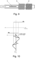
- bistable magnetic wire 1 which is connected to a moving piston, is used for measurement the linear position with high accuracy.
- the bistable magnetic wire 1 in this example with the composition Fe 77.5 Si 7.5 B 15 has a positive magnetostriction, has a length of 30 mm, a metal core diameter of 39 ⁇ m and a diameter with the glass layer of 71 ⁇ m.
- the excitation element 2 and the sensing element 3 are formed by coils, which loosely surround the sliding piston.
- the longitudinal axes of the excitation element 2, the sensing element 3 and the piston are identical.
- the bistable magnetic wire 1 is mounted on the surface of the piston, so it has only an approximately coaxial position with the excitation element 2 and the sensing element 3, which, however, does not affect the accuracy of the position measurement.
- the asymmetry of the magnetic field in this example is achieved by positional asymmetry, wherein in each position of the piston the center of the bistable magnetic wire 1 is placed outside of the center of the excitation element 2. Moreover, in this example applies, that also both ends 11, 12 are in each position placed outside of the center of the excitation element 2.
- the position of the excitation element 2 is thus set so that at the end position of the piston, one end of the bistable magnetic wire 1 extends inside the coil of the excitation element 2, but does not reach the center of the excitation element 2. Subsequently, the piston with the bistable magnetic wire 1 extends even more from the inside of the coil of the excitation element 2.
- the system according to this example detects the magnetization proportional to the position of the bistable magnetic wire 1.
- a reliable induction method is used for detection of magnetization.
- the excitation field has a triangle-shaped amplitude waveform and the switching time is measured, where T1 and T2 express the magnetization time (positive and negative switching) between the two stable magnetic states according to figure 10 .
- the switching time corresponds to the time when the maximum voltage is induced.
- the maximum and minimum of the received signal can be clearly identified, the background does not affect the interpretation possibilities.
- the correctly amplified and filtered sensed signal is connected to the digital input of a single-chip computer with a time resolution of within 10 ns.
- the simple electronics in the control unit 4 is sufficient to achieve very high accuracy and measurement speed.
- the digital unit of the microcontroller generates a PWM signal of the desired frequency, in this example 135 Hz. After filtering the received signal and transforming it, the times T1 + T2 are sum up by a timer.
- the advantage of the system according to this example is the sharp maximum of the signal induced during the magnetization and the high sensitivity at the level of 10 ⁇ m.
- the system is also independent of the ambient temperature, the measurement error due to temperature sensitivity is less than 0.19%.
- the coil of the excitation element 2 is wound unevenly so that it has an increased number of threads at one end.
- the bistable magnetic wire 1 is positioned so that at a given time of non-zero excitation, the amplitude of the magnetic field excited by the excitation element 2 at the first end 11 is at least 5% different from the amplitude of the magnetic field excited by the excitation element 2 on the second end 12.
Landscapes
- Physics & Mathematics (AREA)
- General Physics & Mathematics (AREA)
- Measurement Of Length, Angles, Or The Like Using Electric Or Magnetic Means (AREA)
- Measuring Magnetic Variables (AREA)
- Transmission And Conversion Of Sensor Element Output (AREA)
Priority Applications (21)
| Application Number | Priority Date | Filing Date | Title |
|---|---|---|---|
| ES22166892T ES2994175T3 (en) | 2022-04-06 | 2022-04-06 | Physical quantity measurement system and/or position measurement with bistable magnetic wire, method of measurement |
| RS20241111A RS66045B1 (sr) | 2022-04-06 | 2022-04-06 | Sistem za merenje fizičkih veličina i/ili za merenje položaja sa bistabilnom magnetnom žicom, postupak merenja |
| HUE22166892A HUE069307T2 (hu) | 2022-04-06 | 2022-04-06 | Fizikai mennyiség mérõrendszer és/vagy helyzetmérés bistabil mágneses huzallal, mérési módszer |
| EP22166892.4A EP4257929B1 (en) | 2022-04-06 | 2022-04-06 | Physical quantity measurement system and/or position measurement with bistable magnetic wire, method of measurement |
| PL22166892.4T PL4257929T3 (pl) | 2022-04-06 | 2022-04-06 | Układ do pomiaru wielkości fizycznych i/lub położenia wykorzystujący bistabilny przewód magnetyczny, sposób pomiaru |
| HRP20241383TT HRP20241383T1 (hr) | 2022-04-06 | 2022-04-06 | Sustav za mjerenje fizičkih veličina i/ili za mjerenje položaja sa bistabilnom magnetnom žicom, postupak mjerenja |
| SM20240401T SMT202400401T1 (it) | 2022-04-06 | 2022-04-06 | Sistema di misurazione di grandezza fisica e/o misurazione di posizione con filo magnetico bistabile, metodo di misurazione |
| PCT/IB2023/053187 WO2023194852A1 (en) | 2022-04-06 | 2023-03-30 | Physical quantity measurement system and/or for position measurement with bistable magnetic wire, method of measurement |
| AU2023250422A AU2023250422B2 (en) | 2022-04-06 | 2023-03-30 | Physical quantity measurement system and/or for position measurement with bistable magnetic wire, method of measurement |
| PE2024002162A PE20250248A1 (es) | 2022-04-06 | 2023-03-30 | Sistema de medicion de cantidades fisicas y/o para medicion de posicion con hilo magnetico biestable, metodo de medicion |
| US18/854,006 US20250224258A1 (en) | 2022-04-06 | 2023-03-30 | Physical quantity measurement system and/or for position measurement with bistable magnetic wire, method of measurement |
| KR1020247036922A KR20240169706A (ko) | 2022-04-06 | 2023-03-30 | 쌍안정 자기 와이어를 사용한 물리량 측정 및/또는 포지션 측정 시스템, 측정 방법 |
| CA3246030A CA3246030A1 (en) | 2022-04-06 | 2023-03-30 | SYSTEM FOR MEASURING PHYSICAL QUANTITY AND/OR POSITION WITH A BISTABLE MAGNETIC WIRE, MEASUREMENT METHOD |
| CN202380032712.9A CN118974522A (zh) | 2022-04-06 | 2023-03-30 | 利用双稳态磁线进行物理量测量和/或位置测量的系统,测量方法 |
| JP2024556634A JP2025510817A (ja) | 2022-04-06 | 2023-03-30 | 双安定磁性ワイヤを用いた物理量測定用及び/又は位置測定用システムおよび測定方法 |
| IL316093A IL316093A (en) | 2022-04-06 | 2023-03-30 | A system for measuring a physical quantity or for measuring position using a two-state magnetic wire, a measurement method |
| UY0001040208A UY40208A (es) | 2022-04-06 | 2023-03-31 | Sistema de medida de magnitudes físicas y/o para medida de posición con hilo magnético biestable*** |
| ARP230100849A AR129001A1 (es) | 2022-04-06 | 2023-04-05 | Sistema de medición de magnitudes físicas y/o medición de posición con hilo magnético biestable y método de medición |
| MX2024012232A MX2024012232A (es) | 2022-04-06 | 2024-10-03 | Sistema de medicion de cantidades fisicas y/o para medicion de posiciones con cable magnetico biestable, metodo de medicion |
| CL2024003017A CL2024003017A1 (es) | 2022-04-06 | 2024-10-04 | Sistema de medición de cantidades físicas y/o para medición posición con cable magnético biestable |
| CONC2024/0013915A CO2024013915A2 (es) | 2022-04-06 | 2024-10-16 | Sistema de medición de magnitud física y/o para la medición de posición con alambre magnético biestable, método de medición |
Applications Claiming Priority (1)
| Application Number | Priority Date | Filing Date | Title |
|---|---|---|---|
| EP22166892.4A EP4257929B1 (en) | 2022-04-06 | 2022-04-06 | Physical quantity measurement system and/or position measurement with bistable magnetic wire, method of measurement |
Publications (3)
| Publication Number | Publication Date |
|---|---|
| EP4257929A1 EP4257929A1 (en) | 2023-10-11 |
| EP4257929C0 EP4257929C0 (en) | 2024-08-21 |
| EP4257929B1 true EP4257929B1 (en) | 2024-08-21 |
Family
ID=81940690
Family Applications (1)
| Application Number | Title | Priority Date | Filing Date |
|---|---|---|---|
| EP22166892.4A Active EP4257929B1 (en) | 2022-04-06 | 2022-04-06 | Physical quantity measurement system and/or position measurement with bistable magnetic wire, method of measurement |
Country Status (21)
| Country | Link |
|---|---|
| US (1) | US20250224258A1 (pl) |
| EP (1) | EP4257929B1 (pl) |
| JP (1) | JP2025510817A (pl) |
| KR (1) | KR20240169706A (pl) |
| CN (1) | CN118974522A (pl) |
| AR (1) | AR129001A1 (pl) |
| AU (1) | AU2023250422B2 (pl) |
| CA (1) | CA3246030A1 (pl) |
| CL (1) | CL2024003017A1 (pl) |
| CO (1) | CO2024013915A2 (pl) |
| ES (1) | ES2994175T3 (pl) |
| HR (1) | HRP20241383T1 (pl) |
| HU (1) | HUE069307T2 (pl) |
| IL (1) | IL316093A (pl) |
| MX (1) | MX2024012232A (pl) |
| PE (1) | PE20250248A1 (pl) |
| PL (1) | PL4257929T3 (pl) |
| RS (1) | RS66045B1 (pl) |
| SM (1) | SMT202400401T1 (pl) |
| UY (1) | UY40208A (pl) |
| WO (1) | WO2023194852A1 (pl) |
Families Citing this family (1)
| Publication number | Priority date | Publication date | Assignee | Title |
|---|---|---|---|---|
| DE102024135702B3 (de) * | 2024-12-02 | 2025-11-13 | Schaeffler Technologies AG & Co. KG | Wellgetriebe und Kragenhülse für ein Wellgetriebe mit einer Sensorvorrichtung |
Family Cites Families (20)
| Publication number | Priority date | Publication date | Assignee | Title |
|---|---|---|---|---|
| DE2817169C2 (de) | 1978-04-20 | 1986-10-23 | Robert Bosch Gmbh, 7000 Stuttgart | Einrichtung zur Abgabe von Impulsen |
| JPS55105141U (pl) * | 1979-01-18 | 1980-07-22 | ||
| US4484090A (en) | 1980-02-22 | 1984-11-20 | Echlin Manufacturing Company | Pulse generator with shaped magnetic field |
| DE3008581A1 (de) * | 1980-03-06 | 1981-09-10 | Fa. Dr. Eugen Dürrwächter DODUCO, 7530 Pforzheim | Induktiver weggeber |
| DE3008527C2 (de) * | 1980-03-06 | 1982-04-29 | Fa. Dr. Eugen Dürrwächter DODUCO, 7530 Pforzheim | Schaltungsanordnung zur digitalen Fernübertragung von Signalen |
| DE3427582C2 (de) | 1984-07-26 | 1986-11-27 | Doduco KG Dr. Eugen Dürrwächter, 7530 Pforzheim | Verfahren zum Auslösen von Wiegand-Impulsen |
| JPH03252577A (ja) | 1990-03-02 | 1991-11-11 | Unitika Ltd | 磁界検出法および磁界センサ |
| EP0484716B1 (de) | 1990-11-09 | 1999-01-13 | Siemens Aktiengesellschaft | Elektromagnetischer Geber zur Bestimmung der Drehzahl und/oder Drehrichtung eines Rotors |
| SU1753425A1 (ru) | 1990-12-10 | 1992-08-07 | Ленинградский электротехнический институт им.В.И.Ульянова (Ленина) | Устройство дл определени параметров вращени |
| DE4107847C1 (en) | 1991-03-12 | 1992-09-24 | Mercedes-Benz Aktiengesellschaft, 7000 Stuttgart, De | Impulse sensor using Wiegand effect - has winding connected to single pole switch for short circuiting winding when physical quantity e.g. temp., pressure, acceleration etc. changes |
| DE4407474C2 (de) * | 1994-03-07 | 2000-07-13 | Asm Automation Sensorik Messte | Drehwinkelsensor |
| JP3673413B2 (ja) * | 1998-09-18 | 2005-07-20 | ヒロセ電機株式会社 | パルス信号発生装置 |
| JP3106144B2 (ja) * | 1999-03-30 | 2000-11-06 | 昭 松下 | 複合磁性体の起電力発生装置 |
| GB2374084A (en) | 2001-04-03 | 2002-10-09 | Fourwinds Group Inc | Alloys having bistable magnetic behaviour |
| CN101246203A (zh) * | 2008-04-02 | 2008-08-20 | 吉林大学 | 非晶合金弱磁场传感器 |
| EP2343506B1 (de) * | 2009-12-22 | 2013-06-26 | SICK STEGMANN GmbH | Längenmessvorrichtung |
| CN101887048A (zh) * | 2010-06-25 | 2010-11-17 | 南京航空航天大学 | 高速运行条件下的巴克豪森检测系统及方法 |
| DE102011002179B4 (de) * | 2011-04-19 | 2023-10-12 | Avago Technologies International Sales Pte. Limited | Verfahren und Anordnung zur Synchronisation eines Segmentzählers mit einem Feinpositionssensor |
| US9350216B2 (en) * | 2012-12-28 | 2016-05-24 | Quicksilver Controls, Inc. | Integrated multi-turn absolute position sensor for high pole count motors |
| GB2582123B (en) * | 2018-01-25 | 2021-04-28 | Endomagnetics Ltd | Systems and methods for detecting magnetic markers for surgical guidance |
-
2022
- 2022-04-06 RS RS20241111A patent/RS66045B1/sr unknown
- 2022-04-06 HU HUE22166892A patent/HUE069307T2/hu unknown
- 2022-04-06 SM SM20240401T patent/SMT202400401T1/it unknown
- 2022-04-06 ES ES22166892T patent/ES2994175T3/es active Active
- 2022-04-06 PL PL22166892.4T patent/PL4257929T3/pl unknown
- 2022-04-06 EP EP22166892.4A patent/EP4257929B1/en active Active
- 2022-04-06 HR HRP20241383TT patent/HRP20241383T1/hr unknown
-
2023
- 2023-03-30 WO PCT/IB2023/053187 patent/WO2023194852A1/en not_active Ceased
- 2023-03-30 KR KR1020247036922A patent/KR20240169706A/ko active Pending
- 2023-03-30 US US18/854,006 patent/US20250224258A1/en active Pending
- 2023-03-30 JP JP2024556634A patent/JP2025510817A/ja active Pending
- 2023-03-30 IL IL316093A patent/IL316093A/en unknown
- 2023-03-30 CA CA3246030A patent/CA3246030A1/en active Pending
- 2023-03-30 AU AU2023250422A patent/AU2023250422B2/en active Active
- 2023-03-30 PE PE2024002162A patent/PE20250248A1/es unknown
- 2023-03-30 CN CN202380032712.9A patent/CN118974522A/zh active Pending
- 2023-03-31 UY UY0001040208A patent/UY40208A/es unknown
- 2023-04-05 AR ARP230100849A patent/AR129001A1/es unknown
-
2024
- 2024-10-03 MX MX2024012232A patent/MX2024012232A/es unknown
- 2024-10-04 CL CL2024003017A patent/CL2024003017A1/es unknown
- 2024-10-16 CO CONC2024/0013915A patent/CO2024013915A2/es unknown
Non-Patent Citations (1)
| Title |
|---|
| ZHUKOVA VALENTINA ET AL: "Review of Domain Wall Dynamics Engineering in Magnetic Microwires", NANOMATERIALS, vol. 10, no. 12, 1 December 2020 (2020-12-01), pages 2407, XP093135727, ISSN: 2079-4991, DOI: 10.3390/nano10122407 * |
Also Published As
| Publication number | Publication date |
|---|---|
| WO2023194852A4 (en) | 2023-12-21 |
| MX2024012232A (es) | 2024-12-06 |
| HRP20241383T1 (hr) | 2024-12-20 |
| AU2023250422A1 (en) | 2024-10-10 |
| AU2023250422B2 (en) | 2025-08-14 |
| CA3246030A1 (en) | 2023-10-12 |
| CN118974522A (zh) | 2024-11-15 |
| UY40208A (es) | 2023-08-31 |
| PE20250248A1 (es) | 2025-01-29 |
| RS66045B1 (sr) | 2024-11-29 |
| IL316093A (en) | 2024-12-01 |
| WO2023194852A1 (en) | 2023-10-12 |
| ES2994175T3 (en) | 2025-01-20 |
| AR129001A1 (es) | 2024-07-03 |
| JP2025510817A (ja) | 2025-04-15 |
| SMT202400401T1 (it) | 2024-11-15 |
| EP4257929A1 (en) | 2023-10-11 |
| EP4257929C0 (en) | 2024-08-21 |
| PL4257929T3 (pl) | 2024-12-23 |
| CL2024003017A1 (es) | 2024-12-13 |
| KR20240169706A (ko) | 2024-12-03 |
| HUE069307T2 (hu) | 2025-02-28 |
| US20250224258A1 (en) | 2025-07-10 |
| CO2024013915A2 (es) | 2024-10-31 |
Similar Documents
| Publication | Publication Date | Title |
|---|---|---|
| CN101563585B (zh) | 被测物相对于传感器的位置和/或位置变化的测定方法及测定用的传感器装置 | |
| EP2938983A2 (en) | Non-contact magnetostrictive sensing systems and methods | |
| US9574865B2 (en) | Method and apparatus for sensing magnetic fields | |
| EP0855018A4 (en) | INDUCTIVE SENSOR FOR MONITORING THE LEVEL AND OF THE DISPLACEMENT OF A FLUID AND OF DISPLACEMENTS | |
| JP2016509232A (ja) | 磁気リニアまたはロータリエンコーダ | |
| US4769599A (en) | Magnetometer with magnetostrictive member of stress variable magnetic permeability | |
| EP4257929B1 (en) | Physical quantity measurement system and/or position measurement with bistable magnetic wire, method of measurement | |
| US20130221950A1 (en) | Method and measurement arrangement for measuring mechanical stresses in ferromagnetic workpieces | |
| US6192754B1 (en) | Sensor system for measuring displacements | |
| Deng et al. | A new model of the signal generation mechanism on magnetostrictive position sensor | |
| Chi et al. | A new multifunctional tactile sensor for three-dimensional force measurement | |
| Ricken et al. | Improved multi-sensor for force measurement of pre-stressed steel cables by means of the eddy current technique | |
| Jacko et al. | Linear position sensor using magnetically bistable microwire | |
| Xue et al. | Rotation angle detection based on low-frequency giant magnetoimpedance effect | |
| MD4257929T2 (ro) | Sistem de măsurare a mărimilor fizice și/sau de măsurare a poziției cu fir magnetic bistabil, metodă de măsurare | |
| Fosalau et al. | Circular displacement sensor using magnetostrictive amorphous wires | |
| JP3500966B2 (ja) | 応力測定方法及び近似関数の特定方法 | |
| JPH0331782A (ja) | 磁気式エンコーダー | |
| Inozemtsev et al. | Selection and experimental study of the linear displacement converter for the automated monitoring system of mine roofs | |
| SU1260670A1 (ru) | Способ неразрушающего контрол изделий | |
| CN113296035B (zh) | 一种磁场检测组件、一种铁磁性及磁性材料探测器 | |
| Pandaram et al. | Automated Deformation Detection System for Tubes and Rods in Manufacturing Industries Using Quasi Digital Sensors | |
| Hilko et al. | Determination of magnetic field intensity on open sample | |
| RU2622509C1 (ru) | Электромагнитный многосекторный дефектоскоп | |
| WO2024023807A1 (en) | Device and method for measuring topologically protected surface magnon |
Legal Events
| Date | Code | Title | Description |
|---|---|---|---|
| REG | Reference to a national code |
Ref country code: HR Ref legal event code: TUEP Ref document number: P20241383T Country of ref document: HR |
|
| PUAI | Public reference made under article 153(3) epc to a published international application that has entered the european phase |
Free format text: ORIGINAL CODE: 0009012 |
|
| STAA | Information on the status of an ep patent application or granted ep patent |
Free format text: STATUS: THE APPLICATION HAS BEEN PUBLISHED |
|
| AK | Designated contracting states |
Kind code of ref document: A1 Designated state(s): AL AT BE BG CH CY CZ DE DK EE ES FI FR GB GR HR HU IE IS IT LI LT LU LV MC MK MT NL NO PL PT RO RS SE SI SK SM TR |
|
| STAA | Information on the status of an ep patent application or granted ep patent |
Free format text: STATUS: REQUEST FOR EXAMINATION WAS MADE |
|
| 17P | Request for examination filed |
Effective date: 20231220 |
|
| RAV | Requested validation state of the european patent: fee paid |
Extension state: TN Effective date: 20231220 Extension state: MD Effective date: 20231220 Extension state: MA Effective date: 20231220 Extension state: KH Effective date: 20231220 |
|
| RAX | Requested extension states of the european patent have changed |
Extension state: ME Payment date: 20231220 Extension state: BA Payment date: 20231220 |
|
| RBV | Designated contracting states (corrected) |
Designated state(s): AL AT BE BG CH CY CZ DE DK EE ES FI FR GB GR HR HU IE IS IT LI LT LU LV MC MK MT NL NO PL PT RO RS SE SI SK SM TR |
|
| GRAP | Despatch of communication of intention to grant a patent |
Free format text: ORIGINAL CODE: EPIDOSNIGR1 |
|
| STAA | Information on the status of an ep patent application or granted ep patent |
Free format text: STATUS: GRANT OF PATENT IS INTENDED |
|
| RIC1 | Information provided on ipc code assigned before grant |
Ipc: G01P 3/481 20060101ALN20240305BHEP Ipc: G01D 5/14 20060101AFI20240305BHEP |
|
| INTG | Intention to grant announced |
Effective date: 20240320 |
|
| GRAS | Grant fee paid |
Free format text: ORIGINAL CODE: EPIDOSNIGR3 |
|
| GRAA | (expected) grant |
Free format text: ORIGINAL CODE: 0009210 |
|
| STAA | Information on the status of an ep patent application or granted ep patent |
Free format text: STATUS: THE PATENT HAS BEEN GRANTED |
|
| AK | Designated contracting states |
Kind code of ref document: B1 Designated state(s): AL AT BE BG CH CY CZ DE DK EE ES FI FR GB GR HR HU IE IS IT LI LT LU LV MC MK MT NL NO PL PT RO RS SE SI SK SM TR |
|
| REG | Reference to a national code |
Ref country code: GB Ref legal event code: FG4D |
|
| REG | Reference to a national code |
Ref country code: CH Ref legal event code: EP |
|
| REG | Reference to a national code |
Ref country code: IE Ref legal event code: FG4D |
|
| REG | Reference to a national code |
Ref country code: DE Ref legal event code: R096 Ref document number: 602022005413 Country of ref document: DE |
|
| U01 | Request for unitary effect filed |
Effective date: 20240917 |
|
| U07 | Unitary effect registered |
Designated state(s): AT BE BG DE DK EE FI FR IT LT LU LV MT NL PT RO SE SI Effective date: 20241007 |
|
| REG | Reference to a national code |
Ref country code: GR Ref legal event code: EP Ref document number: 20240402377 Country of ref document: GR Effective date: 20241111 |
|
| REG | Reference to a national code |
Ref country code: HR Ref legal event code: T1PR Ref document number: P20241383 Country of ref document: HR |
|
| REG | Reference to a national code |
Ref country code: MD Ref legal event code: VAGR Ref document number: 4257929 Country of ref document: MD Date of ref document: 20241231 Kind code of ref document: T2 |
|
| REG | Reference to a national code |
Ref country code: ES Ref legal event code: FG2A Ref document number: 2994175 Country of ref document: ES Kind code of ref document: T3 Effective date: 20250120 |
|
| REG | Reference to a national code |
Ref country code: SK Ref legal event code: T3 Ref document number: E 45453 Country of ref document: SK |
|
| REG | Reference to a national code |
Ref country code: HU Ref legal event code: AG4A Ref document number: E069307 Country of ref document: HU |
|
| U20 | Renewal fee for the european patent with unitary effect paid |
Year of fee payment: 4 Effective date: 20250303 |
|
| PGFP | Annual fee paid to national office [announced via postgrant information from national office to epo] |
Ref country code: MC Payment date: 20250320 Year of fee payment: 4 |
|
| PGFP | Annual fee paid to national office [announced via postgrant information from national office to epo] |
Ref country code: HR Payment date: 20250319 Year of fee payment: 4 Ref country code: IS Payment date: 20250319 Year of fee payment: 4 |
|
| REG | Reference to a national code |
Ref country code: HR Ref legal event code: ODRP Ref document number: P20241383 Country of ref document: HR Payment date: 20250319 Year of fee payment: 4 |
|
| PGFP | Annual fee paid to national office [announced via postgrant information from national office to epo] |
Ref country code: SM Payment date: 20250325 Year of fee payment: 4 |
|
| PGFP | Annual fee paid to national office [announced via postgrant information from national office to epo] |
Ref country code: IE Payment date: 20250317 Year of fee payment: 4 |
|
| PGFP | Annual fee paid to national office [announced via postgrant information from national office to epo] |
Ref country code: NO Payment date: 20250314 Year of fee payment: 4 |
|
| PGFP | Annual fee paid to national office [announced via postgrant information from national office to epo] |
Ref country code: GR Payment date: 20250318 Year of fee payment: 4 |
|
| PGFP | Annual fee paid to national office [announced via postgrant information from national office to epo] |
Ref country code: CZ Payment date: 20250314 Year of fee payment: 4 Ref country code: PL Payment date: 20250303 Year of fee payment: 4 |
|
| PGFP | Annual fee paid to national office [announced via postgrant information from national office to epo] |
Ref country code: SK Payment date: 20250313 Year of fee payment: 4 |
|
| PGFP | Annual fee paid to national office [announced via postgrant information from national office to epo] |
Ref country code: RS Payment date: 20250320 Year of fee payment: 4 |
|
| PGFP | Annual fee paid to national office [announced via postgrant information from national office to epo] |
Ref country code: TR Payment date: 20250310 Year of fee payment: 4 |
|
| VSFP | Annual fee paid to validation state [announced via postgrant information from national office to epo] |
Ref country code: MD Payment date: 20250321 Year of fee payment: 4 |
|
| PLBE | No opposition filed within time limit |
Free format text: ORIGINAL CODE: 0009261 |
|
| STAA | Information on the status of an ep patent application or granted ep patent |
Free format text: STATUS: NO OPPOSITION FILED WITHIN TIME LIMIT |
|
| PGFP | Annual fee paid to national office [announced via postgrant information from national office to epo] |
Ref country code: ES Payment date: 20250507 Year of fee payment: 4 |
|
| PGFP | Annual fee paid to national office [announced via postgrant information from national office to epo] |
Ref country code: HU Payment date: 20250314 Year of fee payment: 4 |
|
| PGFP | Annual fee paid to national office [announced via postgrant information from national office to epo] |
Ref country code: CH Payment date: 20250501 Year of fee payment: 4 |
|
| 26N | No opposition filed |
Effective date: 20250522 |
|
| PGFP | Annual fee paid to national office [announced via postgrant information from national office to epo] |
Ref country code: CY Payment date: 20250318 Year of fee payment: 4 |