EP4257828A1 - Deckel für eine blattheizwärmepumpe und wärmepumpe - Google Patents
Deckel für eine blattheizwärmepumpe und wärmepumpe Download PDFInfo
- Publication number
- EP4257828A1 EP4257828A1 EP23165164.7A EP23165164A EP4257828A1 EP 4257828 A1 EP4257828 A1 EP 4257828A1 EP 23165164 A EP23165164 A EP 23165164A EP 4257828 A1 EP4257828 A1 EP 4257828A1
- Authority
- EP
- European Patent Office
- Prior art keywords
- heating
- section
- heating element
- temperature
- heat pump
- Prior art date
- Legal status (The legal status is an assumption and is not a legal conclusion. Google has not performed a legal analysis and makes no representation as to the accuracy of the status listed.)
- Granted
Links
Images


Classifications
-
- F—MECHANICAL ENGINEERING; LIGHTING; HEATING; WEAPONS; BLASTING
- F24—HEATING; RANGES; VENTILATING
- F24H—FLUID HEATERS, e.g. WATER OR AIR HEATERS, HAVING HEAT-GENERATING MEANS, e.g. HEAT PUMPS, IN GENERAL
- F24H1/00—Water heaters, e.g. boilers, continuous-flow heaters or water-storage heaters
- F24H1/10—Continuous-flow heaters, i.e. heaters in which heat is generated only while the water is flowing, e.g. with direct contact of the water with the heating medium
- F24H1/101—Continuous-flow heaters, i.e. heaters in which heat is generated only while the water is flowing, e.g. with direct contact of the water with the heating medium using electric energy supply
- F24H1/102—Continuous-flow heaters, i.e. heaters in which heat is generated only while the water is flowing, e.g. with direct contact of the water with the heating medium using electric energy supply with resistance
-
- F—MECHANICAL ENGINEERING; LIGHTING; HEATING; WEAPONS; BLASTING
- F04—POSITIVE - DISPLACEMENT MACHINES FOR LIQUIDS; PUMPS FOR LIQUIDS OR ELASTIC FLUIDS
- F04D—NON-POSITIVE-DISPLACEMENT PUMPS
- F04D29/00—Details, component parts, or accessories
- F04D29/58—Cooling; Heating; Diminishing heat transfer
- F04D29/586—Cooling; Heating; Diminishing heat transfer specially adapted for liquid pumps
-
- F—MECHANICAL ENGINEERING; LIGHTING; HEATING; WEAPONS; BLASTING
- F04—POSITIVE - DISPLACEMENT MACHINES FOR LIQUIDS; PUMPS FOR LIQUIDS OR ELASTIC FLUIDS
- F04D—NON-POSITIVE-DISPLACEMENT PUMPS
- F04D29/00—Details, component parts, or accessories
- F04D29/40—Casings; Connections of working fluid
- F04D29/406—Casings; Connections of working fluid especially adapted for liquid pumps
-
- F—MECHANICAL ENGINEERING; LIGHTING; HEATING; WEAPONS; BLASTING
- F04—POSITIVE - DISPLACEMENT MACHINES FOR LIQUIDS; PUMPS FOR LIQUIDS OR ELASTIC FLUIDS
- F04D—NON-POSITIVE-DISPLACEMENT PUMPS
- F04D29/00—Details, component parts, or accessories
- F04D29/60—Mounting; Assembling; Disassembling
- F04D29/605—Mounting; Assembling; Disassembling specially adapted for liquid pumps
-
- F—MECHANICAL ENGINEERING; LIGHTING; HEATING; WEAPONS; BLASTING
- F24—HEATING; RANGES; VENTILATING
- F24H—FLUID HEATERS, e.g. WATER OR AIR HEATERS, HAVING HEAT-GENERATING MEANS, e.g. HEAT PUMPS, IN GENERAL
- F24H15/00—Control of fluid heaters
- F24H15/20—Control of fluid heaters characterised by control inputs
- F24H15/212—Temperature of the water
-
- H—ELECTRICITY
- H05—ELECTRIC TECHNIQUES NOT OTHERWISE PROVIDED FOR
- H05B—ELECTRIC HEATING; ELECTRIC LIGHT SOURCES NOT OTHERWISE PROVIDED FOR; CIRCUIT ARRANGEMENTS FOR ELECTRIC LIGHT SOURCES, IN GENERAL
- H05B1/00—Details of electric heating devices
- H05B1/02—Automatic switching arrangements specially adapted to apparatus ; Control of heating devices
- H05B1/0227—Applications
- H05B1/023—Industrial applications
- H05B1/0244—Heating of fluids
-
- H—ELECTRICITY
- H05—ELECTRIC TECHNIQUES NOT OTHERWISE PROVIDED FOR
- H05B—ELECTRIC HEATING; ELECTRIC LIGHT SOURCES NOT OTHERWISE PROVIDED FOR; CIRCUIT ARRANGEMENTS FOR ELECTRIC LIGHT SOURCES, IN GENERAL
- H05B3/00—Ohmic-resistance heating
- H05B3/02—Details
- H05B3/06—Heater elements structurally combined with coupling elements or holders
-
- H—ELECTRICITY
- H05—ELECTRIC TECHNIQUES NOT OTHERWISE PROVIDED FOR
- H05B—ELECTRIC HEATING; ELECTRIC LIGHT SOURCES NOT OTHERWISE PROVIDED FOR; CIRCUIT ARRANGEMENTS FOR ELECTRIC LIGHT SOURCES, IN GENERAL
- H05B3/00—Ohmic-resistance heating
- H05B3/40—Heating elements having the shape of rods or tubes
- H05B3/42—Heating elements having the shape of rods or tubes non-flexible
- H05B3/44—Heating elements having the shape of rods or tubes non-flexible heating conductor arranged within rods or tubes of insulating material
-
- A—HUMAN NECESSITIES
- A47—FURNITURE; DOMESTIC ARTICLES OR APPLIANCES; COFFEE MILLS; SPICE MILLS; SUCTION CLEANERS IN GENERAL
- A47L—DOMESTIC WASHING OR CLEANING; SUCTION CLEANERS IN GENERAL
- A47L15/00—Washing or rinsing machines for crockery or tableware
- A47L15/42—Details
- A47L15/4285—Water-heater arrangements
-
- F—MECHANICAL ENGINEERING; LIGHTING; HEATING; WEAPONS; BLASTING
- F24—HEATING; RANGES; VENTILATING
- F24H—FLUID HEATERS, e.g. WATER OR AIR HEATERS, HAVING HEAT-GENERATING MEANS, e.g. HEAT PUMPS, IN GENERAL
- F24H2250/00—Electrical heat generating means
- F24H2250/02—Resistances
-
- H—ELECTRICITY
- H05—ELECTRIC TECHNIQUES NOT OTHERWISE PROVIDED FOR
- H05B—ELECTRIC HEATING; ELECTRIC LIGHT SOURCES NOT OTHERWISE PROVIDED FOR; CIRCUIT ARRANGEMENTS FOR ELECTRIC LIGHT SOURCES, IN GENERAL
- H05B2203/00—Aspects relating to Ohmic resistive heating covered by group H05B3/00
- H05B2203/014—Heaters using resistive wires or cables not provided for in H05B3/54
-
- H—ELECTRICITY
- H05—ELECTRIC TECHNIQUES NOT OTHERWISE PROVIDED FOR
- H05B—ELECTRIC HEATING; ELECTRIC LIGHT SOURCES NOT OTHERWISE PROVIDED FOR; CIRCUIT ARRANGEMENTS FOR ELECTRIC LIGHT SOURCES, IN GENERAL
- H05B2203/00—Aspects relating to Ohmic resistive heating covered by group H05B3/00
- H05B2203/021—Heaters specially adapted for heating liquids
Definitions
- the present disclosure relates to the technical field of heating appliance, in particular to a blade-heating heat pump cover and a heat pump.
- automated home appliances provide more functions to assist people's live, such as automatic dishwashers, water heaters, and water dispensers, etc. those appliances can drive the water flow through the pump body and heat the liquid in the pump body at the same time, thus providing convenience for people's live.
- the heat tubes in the commercially available heat pumps are all tubular and provided in the interior of the pump body. Since the heating tubes are in direct contact with the liquid medium, the heating tubes are prone to corrosion with the increase of usage time, which can lead to current leakage, and result in the risk of electric shock during the use of the user.
- the heating tubes of the heat pump in the prior art are tubular structures provided in the interior of the pump body, and the heating tubes are in direct contact with the liquid medium, which makes the heating tubes be easily corroded to cause current leakage, and brings the hidden danger to the users in installation and use, the present disclosure provides a blade-heating heat pump cover and a heat pump.
- the first end comprises a heating section and a non-heating section
- the non-heating section is located on one side of the heating section away from the second end
- the heating section is fixedly connected to the second surface inside the mounting slot.
- a length of the non-heating section is 3mm - 80mm.
- the non-heating section is bent relative to the second surface at a predetermined angle.
- a ratio of a length along the radial direction of the heating element to a length along the axial direction of the heating element is not less than 2.3.
- the heating element further comprises a bending section, the bending section is provided on the second end, a power density at a surface of the bending section is less than a power density at a surface of each other sections on the heating element.
- a clamp section is provided inside the mounting slot, the clamp section is provided to protrude from the first surface to the second surface;
- a matching section is provided on a part of the heating element corresponding to the clamp section, a shape of the matching section is adapted to a shape of the clamp section, the matching section is provided along a center line of the heating section, the heating wire is set on two sides of the matching section.
- the heating section is set to have a predetermined distance between an inner side wall and an outer side wall of the mounting slot, and the predetermined distance is 1mm to 100mm.
- an electrically-connected section is provided on the second end, the electrically-connected section is connected to the heating wire in circuit;
- the blade-heating heat pump cover further comprises a temperature-controlling assembly, the temperature-controlling assembly is connected to the electrically-connected section in circuit, the temperature-controlling assembly is set on one side of the heating element corresponding to the second surface.
- the electrically-connected section comprises a first wiring post and a second wiring post, and two ends of the heating wire are respectively connected to the first wiring post and the second wiring post;
- the heating element further comprises a sheath, and an insulating filler, the heating wire is set inside the sheath, the insulating filler is filled in a position between the heating wire and the sheath.
- the temperature-controlling assembly comprises a first plug and a second plug, the first plug is connected to the first wiring post in circuit, and the second plug is connected to the second wiring post in circuit.
- the temperature-controlling assembly comprises:
- a safety device a bottom of the safety device is embedded on a position of the positioning plate corresponding to the temperature-sensing piece.
- the temperature-sensing piece further comprises a first side plate and a second side plate, the first side plate and the second side plate are respectively fixedly connected to an inner side and an outer side of the heating element, and one side of the first side plate facing the cover body and one side of the second side plate facing the cover body are respectively fixedly connected to the second surface of the cover body.
- the temperature-controlling assembly further comprises a controlling plug, the controlling plug is fixedly set on the temperature controller and the safety device.
- the controlling plug further comprises a third plug and a fourth plug, a distance between the third plug and the fourth plug is 5mm ⁇ 0.5mm, the third plug and the fourth plug are configured to connect a power supply.
- a first mounting post and a second mounting post are fixedly provided on the temperature-sensing piece, the positioning plate is detachably fitted onto the first mounting post and the second mounting post.
- a cross-sectional contour shape of the clamp section is one of a triangle, a semicircle, a rectangle, and a trapezoid.
- a heat pump the heat pump comprises the blade-heating heat pump cover according to any one of above.
- the beneficial effects of the present disclosure are at least as follows: by providing the mounting slot on the cover body in a direction of protruding from the second surface to the first surface, and providing the heating element in the mounting slot, the present disclosure makes the heating element be provided on the cover body without contacting the liquid medium, and the liquid medium be heated through the cover body, thus avoiding the occurrence of leakage caused by corrosion of the heating element by the liquid medium; by providing the heating wire in the heating element, and bending and providing the heating wire in the first end of the heating element for heating, and one part of the heating wire being located on the second end of the heating element being connected to the external circuit, the present disclosure is easy to install, assembly and maintain.
- the heating tubes in the commercially available heat pump are tubular.
- the heating tubes are provided in the interior of the pump body, and the heating tubes are in direct contact with the liquid medium, with the increase of usage time the heating tubes are prone to corrosion, which leads to the risk of leakage, thus resulting in the risk of electric shock during the use of the user.
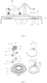
- the blade-heating heat pump cover comprises a cover body 100, the cover body 100 comprises a first surface 101 contacting a liquid, and a second surface 102 opposed to the first surface 101, characterized in that the cover body 100 is provided with a mounting slot 110 protruding from the second surface 102 to the first surface 101, the mounting slot 110 is provided in a shape of a ring; a heating element 200, the heating element 200 is embeddedly provided in the mounting slot 110, the heating element 200 comprises a first end 210 positioned in the mounting slot 110, and a second end 220 protruding from the mounting slot 110, the heating element 200 is provided with a heating wire 230, the heating wire 230 is bent and provided in the first end 210, and the heating wire is connected to an external circuit at the second end 220.
- the present disclosure by providing the mounting slot 110 protruding from from the second surface 102 to the first surface 101 on the cover body 100, and providing a heating element 200 inside the mounting slot 110, so that the heating element 200 is provided on the cover body 100 without contacting a liquid medium, by heating the liquid medium through the cover body 100, thus avoiding the occurrence of leakage caused by corrosion of the heating element 200 by the liquid medium, by providing the heating wire 230 inside the heating element 200, the heating wire 230 is bent and provided inside the first end 210 of the heating element 200 for heating, and a section of the heating wire 230 positioned at the second end 220 of the heating element 200 is connected to the external circuit, which is easy to install assembly and maintain.
- a main body of the blade-heating heat pump cover of the present disclosure is the cover body 100, which is used to connect and fix with a pump housing in household appliances, and the heating element 200 provided on the cover body 100 generates heat during a working process, which can realize the heating of a liquid medium contacting the cover body 100, so that users can use a heated liquid, and in this embodiment, in order to avoid the problem of short circuit easily occurring after a contact between the heating element 200 and the liquid medium with aging of usage time, the present disclosure provides the heating element 200 on one side of the cover body 100, and when the heating element 200 starts working, one side of a contact surface on the cover body 100 can heat the liquid medium by a heat conduction through the cover body 100.
- one side of the cover body 100 contacting the liquid medium is the first surface 101
- one side of the cover body 100 opposed to the first surface 101 is the second surface 102
- the mounting slot 110 is provided protrudingly from one side of the second surface 102 on the cover body 100 to one side of the first surface 101, so that the heating element 200 is embedded and fixed in the mounting slot 110, and also a contact area between the cover body 100 and the liquid medium is increased, thus achieving an effect of increasing a heating speed of the liquid medium.
- a shape of the heating element 200 in the present disclosure is a rectangular shape similar to a blade, herein a purpose is to increase a contact area between the heating element 200 and the mounting slot 110, while to ensure that the heating element 200 and the mounting slot 110 fit closely, in an actual setting, the heating element 200 and the mounting slot 110 can be fixed by brazing and soldering and other welding methods, it should be noted to choose a heat-conducting material as a fixed material, while to completely fill a gap between the heating element 200 and the mounting slot 110 in order to improve a heat-conducting efficiency.
- the heating wire 230 is also provided inside the heating element 200, and the heating wire 230 is made of a high-resistance alloy material, which can convert electrical energy into heat energy, and in this application, an electric heating wire is bent and provided inside the heating element 200 to ensure an uniformity of heat conduction, and for convenient description, the heating element 200 is also divided into the first end 210 and the second end 220 in the present disclosure, wherein the first end 210 of the heating element 200 is embedded in the mounting slot 110 for heating, and the second end 220 of the heating element 200 is protrudingly provided on an outside of the mounting slot 110, and the second end 220 is connected to the external circuit, herein easy to assemble in a producing process, while not to affect a length of the heating element 200 fitted with the mounting slot 110 to ensure a heating effect.
- the first end 210 also comprises a heating section 211 and a non-heating section 212, wherein the non-heating section 212 is located on one side of the heating section 211 away from the second end 220, and the heating section 211 is fixedly connected to the second surface 102 inside the mounting slot 110 herein providing the non-heating section 212 is to make an avoidance space occur between two ends of the heating element 200 surrounding the mounting slot 110, mainly aiming to facilitate an installation of a temperature-controlling assembly 300, so that the temperature-controlling assembly is not only sensitive to a temperature of the blade-heating heating element 200 but also sensitive to a temperature of the liquid, thus a fixed temperature difference existed between a sensed temperature by the temperature-controlling assembly 300 and the liquid in contact with the first surface 101 of the pump, and improving a temperature-controlling accuracy.
- a length of the non-heating section 212 is from 3mm to 80mm, which can be adjusted by the skilled in the art
- the first end 210 of the heating element 200 has two forms of settings, one of which is to set the non-heating section 212 directly fitted to an inside of the mounting slot 110, and another of which is to bend the non-heating section 212 relative to the second surface 102 at a predetermined angle to facilitate an installation staff, and in an embodiment, it is also preferred to provide a plug 240 on the non-heating section 212 for protecting the heating element 200, and the plug 240 is made of an insulating material, which can realize a wrapping of one end of the heating element 200 to avoid a short circuit caused by the liquid entering into the heating element 200.
- a ratio of a length of the heating element 200 along a radial direction to a length of an heating body along an axial direction in this application should be not less than 2.3, i.e. the heating element 200 in this application is set in a shape similar to a blade, so that the heating element 200 can be closely fitted in the mounting slot 110 during assembly, thus increasing a contact area between the heating element 200 and a bottom plate of the mounting slot 110, and improving a ratio of heat supply to ensure a fast heating process.
- the heating element 200 also comprises a bending section 250, the bending section 250 is set on the second end 220, an angle is set between the bending section 250 and the second surface 102 of the cover body 100, to achieve setting the second end 220 protruding out of the mounting slot 110, in a specific setting, a power density at a surface of the bending section 250 should be less than a power density at a surface of other sections of the heating body, i.e. the second end 220 where the bending section 250 is located is not involved in a heat conduction to the sheath 280, thus reducing a heat generated by the second end 220 to reduce energy loss.
- the embodiment also providing a clamp section 111 inside the mounting slot 110 the clamp section is provided along one side of the first surface 101 of the cover body 100 protruding to one side of the second surface 102, correspondingly, in the embodiment also providing a matching section 260 on a part of the heating element 200 corresponding to the clamp section 111, a shape of the matching section 260 is adapted to a shape of the clamp section 111, and in an actual setting, it is preferred to set the matching section 260 along a center line of the heating section 211, and at the same time, in the interior of the heating element 200, the bent heating wire 230 is fitted to two sides of the matching section 260 to achieve an effect of uniform heat conduction.
- the heating element 200 When the heating element 200 is fitted to the bottom of the mounting slot 110, the heating element 200 is set riding across the clamp section 111, increasing a contact area between the heating element 200 and the cover body 100 while also being able to position the heating element 200, effectively avoiding a problem of different mounting positions of the product heating element 200 due to factors such as welding, mounting order etc. during a producing process, and ensuring a consistency of a producing quality of the blade-heating heat pump cover.
- a cross-sectional contour of the clamp section 111 may be set as triangle, semicircle, rectangle, trapezoid, etc.
- a predetermined distance is set between one side of the heating element 200 and an inner side wall of the mounting slot 110, and a predetermined distance is set between one side of the heating element 200 and an outer side wall of the mounting slot 110, with the predetermined distance ranging from 1mm to 100mm, there is an advantage of making a heat generated by the heating element 200 concentrate on a bottom part of the heating element 200 not involved in providing heat, and facilitating a part of the heating element 200 not involved in providing heat can quickly dissipate heat.
- the inner side wall and the outer side wall of the mounting slot 110 are not in direct contact with the heating element 200, thus also avoiding a risk of aging and accidental fire caused by a high temperature at a matching of an inlet pipe and a corresponding assembled pump housing with plastic and rubber material, and improving the pump body's life and increasing safety.
- an electrically-connected section 270 is set on the second end 220, the electrically-connected section 270 is connected to the heating wire 230 in circuit when in an actual setting, one function of the electrically-connected section 270 is to close the second end 220 of the heating element 200 to avoid water vapor, liquid, etc.
- the above blade-heating heat pump cover also comprises the temperature-controlling assembly 300, the temperature-controlling assembly 300 is connected to the above electrical heating section 211 in circuit, and the temperature-controlling assembly 300 is fitted and set on one side of the above heating element 200 corresponding to the second surface 102.
- the above electrically-connected section 270 comprises a first wiring post 271 and a second wiring post 272, and two ends of the above heating wire 230 are respectively connected with the first wiring post 271 and the second wiring post 272, and at the same time, a first plug 301 and a second plug 302 are set in the above temperature-controlling assembly 300, and the first plug 301 is connected with the above first wiring post 271 in circuit, the second plug 302 is connected with the second wiring post 272 in circuit, so that the temperature-controlling assembly 300 is connected with the heating wire 230 in the heating element 200 in circuit, in use through the temperature-controlling assembly 300 to supply electrical energy to the heating wire 230, achieving the heating wire 230 emergently powered off through the temperature-controlling assembly 300 when a temperature of the heating wire 230 overheating, thus avoiding an occurrence of electrical accidents.
- the above heating element 200 also comprises the sheath 280, and an insulating filler 281, the above heating wire 230 is set inside the sheath 280, in order to avoid the heating wire 230 inside the heating element 200 from contacting the sheath 280 to occur a short circuit, the insulating filler 281 is filled in a gap between the heating wire 230 and the sheath 280, so as to achieve a fixed position of the heating wire 230 and an insulation, and a heat conduction.
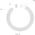
- the heating element 200 can be set up in a form of FIG. 10 in addition to structures of FIG. 1-FIG. 9 to achieve a same technical effect.
- the above heating wire 230 can be set inside the sheath 280, and the gap between the heating wire 230 and the sheath 280 filled with the insulating filler 281.
- a middle part of the heating wire 230 is bent, and then squeezed to form the blade type structure defined in this application, the advantage of which is that in an absence of special equipment to process the blade heating element 200 of Figures 1-9 , a technical effect of professional equipment can be achieved through existing general-purpose equipment, reducing an amount of investment.
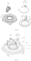
- the above temperature-controlling assembly 300 specifically comprises: a temperature-sensing piece 310, a positioning plate 320, a temperature controller 330, a safety device 340, wherein the temperature-sensing piece 310 is used to form a fit with the above heating element 200 to achieve heat conduction, the positioning plate is used to fix the temperature controller 330 and the safety device, in an actual setting, the positioning plate 320 is provided with holes, bottom of the temperature controller 330 and the safety device 340 are respectively fixedly embedded in the holes, and are respectively against the temperature-sensing piece 310, thus achieving an effect of monitoring an temperature of the heating element 200.
- the above temperature-sensing piece 310 also comprises a first side plate 311 and a second side plate 312, wherein the first side plate 311 and the second side plate 312 are respectively clamped to an inner side and an outer side of the heating element 200, and are fixedly connected to the heating element 200, while one side of the first side plate 311 facing the cover body 100 and one side of the second side plate 312 facing the cover body 100 are respectively fixedly connected to the second surface 102 of the cover body 100 so that a heat of the liquid inside the pump can be conducted to the temperature-sensing piece 310 through the cover body 100.
- the advantage of such a setting is that through the temperature-sensing piece 310 the temperature-controlling assembly 300 is sensitive not only to a temperature of the heating element 200, but also to a temperature of the liquid inside the pump, thus forming a temperature difference between the temperature-sensing piece 310 and the temperature of the liquid in a normal working stage, the temperature difference can improve a control accuracy of the temperature-controlling assembly 300 to the liquid temperature.
- the present disclosure also provides one way of setting, as shown in FIG. 8 , the temperature-sensing piece 310 in an actual setting may be set without the first side plate 311 and the second side plate 312, i.e. fixing the temperature-sensing piece 310 with the heating element 200 only by fitting the temperature-sensing piece 310 to the heating element 200.
- a part of the temperature-sensing piece 310 is correspondingly provided in the heating section 211 of the heating element 200, and another part of the temperature-sensing piece 310 is provided in the non-heating section 212 of the heating element 200.
- a heat of the liquid in the pump may be conducted to the temperature-sensing piece 310 through the cover body 100 and a pipe wall of the non-heating section 212 of the heating element 200, so that the temperature-sensing sheet 300 may detect the heat of the liquid in the pump conducted through the non-heating section 212, and may also detect the heat of the heating element 200 conducted through the heating section 211, so that the temperature-controlling device mounted to the temperature-sensing piece 310 is sensitive to both the temperature of the heating element 200 and the temperature of the liquid.
- the above temperature-controlling assembly 300 also comprises a control plug 350, the control plug 350 is fixedly set on the temperature controller 330 and the safety device 340, in an actual setting, the control plug 350 may be specifically set using a connector such as RAST5 etc. to achieve an effect of connecting with power supply.
- the control plug 350 may be specifically set using a connector such as RAST5 etc. to achieve an effect of connecting with power supply.
- the temperature controller 330 and the safety device 340 may be wrapped by a housing of the control plug 350 to ensure a stability of mounting
- two sides of the control plug 350 are also provided reinforcing bars, the reinforcing bars are used to support the two sides of the control plug 350 to avoid a deformation of the control plug 350 due to long-term stress concentration
- the above first plug 301 and the above second plug 302 are connected with the temperature controller 330 and safety device 340 in circuit respectively, thus achieve an effect of controlling a temperature of the heating body through the circuit.
- the control plug 350 also comprises a third plug 351 and a fourth plug 352, the third plug 351 and the fourth plug 352 are set at intervals and are parallel to each other, and the third plug 351 and the fourth plug 352 are respectively connected to the temperature controller 330 and the safety device 340 in circuit, through the third plug 351 and the fourth plug 352, connecting the control plug 350 to an external power supply may be achieved.
- a distance between the third plug 351 and the fourth plug 352 should be limited to 5mm ⁇ 0.5mm to achieve an effect of matching with a matching power connector.
- a first anti-shedding hole is also provided on the above third plug 351, and the first anti-shedding hole is pass-through set in the third plug 351, a tight connection between the third plug 351 and the matching power plug can be realized through the first anti-shedding hole to prevent shedding; correspondingly, a second anti-shedding hole is also pass-through set in the fourth plug 352.
- a second anti-shedding hole is also pass-through set in the fourth plug 352.
- contour shapes of the temperature-sensing piece 310 and the positioning plate 320 are adapted to each other, and in order to realize a fixation of the temperature-controlling assembly 300, in this embodiment also providing a first mounting post 313 and a second mounting post 314 on the temperature-sensing piece 310, and the temperature-sensing piece 310 and the positioning plate 320 are fixed by fitting the positioning plate 320 onto the first mounting post 313 and the second mounting post 314, and the positioning plate 320 may be also limited by nuts.
- a second embodiment, as shown in FIG. 5 to FIG. 6 in this embodiment, in the blade-heating heat pump cover, the mounting slot 110 of the cover body 100 is provided with the clamp section 111, a shape of the matching section 260 on the heating element 200 is adapted to a shape of the clamp section 111, the heating element 200 is set riding across the clamp section 111, and a plug 240 is also provided on one end of the non-heating section 212 of the heating element 200 for protection, and at the same time, in this embodiment not setting the first side plate 311 and the second side plate 312 on the temperature-sensing piece 310, and the temperature-sensing piece 310 is fitted on the heating section 211 and the non-heating section 212 on the heating element 200 to achieve an effect of monitoring the temperature of the liquid in the pump. And please refer to the description above for settings of other structures in this embodiment.
- a bottom plate of the mounting slot 110 of the cover body 100 is set horizontally, i.e. not setting the clamp section 111, correspondingly, one side of the heating element 200 corresponding to the mounting slot 110 is set to be flat, and the heating element 200 is directly embedded in the mounting slot 110, and at the same time, not setting the first side plate 311 and the second side plate 312 on the temperature-sensing piece 310.
- the temperature-sensing piece 310 is fitted on the heating section 211 and the non-heating section 212 of the heating element 200 to achieve the effect of monitoring the temperature of the liquid in the pump.
- not setting the plug 240 on the heating element 200, and the first end 210 of the heating element 200 is completely fitted in the mounting slot 110.
- the present disclosure also provides a heat pump, the heat pump comprises the blade-heating heat pump cover as described in any one of the above embodiments, the blade-heating heat pump cover specifically comprises: a cover body 100, the cover body 100 comprising a first surface 101 in contact with a liquid, and a second surface 102 opposed to the first surface 101, characterized in that the cover body 100 is provided with a mounting slot 110 set protruding from the second surface 102 to the first surface 101, and the mounting slot 110 is provided in a shape of a ring; a heating element 200, the heating element 200 being embeddedly provided on the mounting slot 110, the heating element 200 comprising a first end 210 located in the mounting slot 110, and a second end 220 protruding from the mounting slot 110, the heating element 200 being provided with a heating wire 230, the heating wire 230 being bent and provided in the first end 210, and the heating wire 230 being connected to an external circuit on the second end 220.
- the present disclosure makes the heating element 200 be provided on the cover body 100 without contacting the liquid medium, and the liquid medium be heated through the cover body 100, thus avoiding the occurrence of leakage caused by corrosion of the heating element 200 by the liquid medium; by providing the heating wire 230 in the heating element 200, and bending and providing the heating wire 230 in the first end 210 of the heating element 200 for heating, and one part of the heating wire 230 being located on the second end 220 of the heating element 200 being connected to the external circuit, the present disclosure is easy to install, assembly and maintain.
- the present disclosure provides a blade-heating heat pump cover and a heat pump, wherein, the blade-heating heat pump cover specifically comprises: a cover body 100, the cover body 100 comprising a first surface 101 in contact with a liquid, and a second surface 102 opposed to the first surface 101, characterized in that the cover body 100 is provided with a mounting slot 110 set protruding from the second surface 102 to the first surface 101, and the mounting slot 110 is provided in a shape of a ring; a heating element 200, the heating element 200 being embeddedly provided on the mounting slot 110, the heating element 200 comprising a first end 210 located in the mounting slot 110, and a second end 220 protruding from the mounting slot 110, the heating element 200 being provided with a heating wire 230, the heating wire 230 being bent and provided in the first end 210, and the heating wire 230 being connected to an external circuit on the second end 220.
- the present disclosure makes the heating element 200 be provided on the cover body 100 without contacting the liquid medium, and the liquid medium be heated through the cover body 100, thus avoiding the occurrence of leakage caused by corrosion of the heating element 200 by the liquid medium; by providing the heating wire 230 in the heating element 200, and bending and providing the heating wire 230 in the first end 210 of the heating element 200 for heating, and one part of the heating wire 230 being located on the second end 220 of the heating element 200 being connected to the external circuit, the present disclosure is easy to install, assembly and maintain.
Landscapes
- Engineering & Computer Science (AREA)
- Mechanical Engineering (AREA)
- General Engineering & Computer Science (AREA)
- Physics & Mathematics (AREA)
- Thermal Sciences (AREA)
- Chemical & Material Sciences (AREA)
- Combustion & Propulsion (AREA)
- Structures Of Non-Positive Displacement Pumps (AREA)
- Cookers (AREA)
Applications Claiming Priority (1)
| Application Number | Priority Date | Filing Date | Title |
|---|---|---|---|
| CN202210361619.XA CN114738321B (zh) | 2022-04-07 | 2022-04-07 | 一种刀片式加热泵盖及加热泵 |
Publications (2)
| Publication Number | Publication Date |
|---|---|
| EP4257828A1 true EP4257828A1 (de) | 2023-10-11 |
| EP4257828B1 EP4257828B1 (de) | 2026-01-28 |
Family
ID=82279744
Family Applications (1)
| Application Number | Title | Priority Date | Filing Date |
|---|---|---|---|
| EP23165164.7A Active EP4257828B1 (de) | 2022-04-07 | 2023-03-29 | Deckel für eine blattheizwärmepumpe und wärmepumpe |
Country Status (3)
| Country | Link |
|---|---|
| US (1) | US20230324077A1 (de) |
| EP (1) | EP4257828B1 (de) |
| CN (1) | CN114738321B (de) |
Families Citing this family (1)
| Publication number | Priority date | Publication date | Assignee | Title |
|---|---|---|---|---|
| CN116538140A (zh) * | 2023-04-26 | 2023-08-04 | 贝克电热科技(深圳)有限公司 | 一种加热泵盖及加热泵 |
Citations (3)
| Publication number | Priority date | Publication date | Assignee | Title |
|---|---|---|---|---|
| US20050201878A1 (en) * | 2004-03-05 | 2005-09-15 | Hans-Juergen Kraffzik | Centrifugal pump |
| EP2821654A1 (de) * | 2013-07-01 | 2015-01-07 | Whirlpool Corporation | Pumpenanordnung für Haushaltsgeräte |
| CN113864242A (zh) * | 2020-06-30 | 2021-12-31 | 三花亚威科电器设备(芜湖)有限公司 | 一种加热泵和具有该加热泵的洗碗机 |
Family Cites Families (10)
| Publication number | Priority date | Publication date | Assignee | Title |
|---|---|---|---|---|
| DE102005018597B3 (de) * | 2005-04-21 | 2006-11-09 | Bleckmann Gmbh & Co. Kg | Heizsystem mit Temperatursicherungseinrichtungen und Wärmeübertragungselement hierfür |
| DE202008015058U1 (de) * | 2008-11-13 | 2009-02-19 | Eichenauer Heizelemente Gmbh & Co. Kg | Beheizbares Pumpengehäuseteil |
| CN103573674B (zh) * | 2013-08-20 | 2015-09-23 | 杭州热威机电有限公司 | 外加热式泵用加热器 |
| WO2015107510A1 (en) * | 2014-01-20 | 2015-07-23 | I.R.C.A. S.P.A. Industria Resistenze Corazzate E Affini | Heater for household appliances |
| EP3013116A1 (de) * | 2014-10-21 | 2016-04-27 | Bleckmann GmbH & Co. KG | Heizungssystemkomponente und Verfahren zur Herstellung davon |
| DE102017118217A1 (de) * | 2017-08-10 | 2019-02-14 | Eichenauer Heizelemente Gmbh & Co. Kg | Beheizbares Pumpengehäuseteil |
| CN108167230B (zh) * | 2017-12-19 | 2020-03-31 | 佛山市威灵洗涤电机制造有限公司 | 加热泵及洗涤电器 |
| CN108852232A (zh) * | 2018-06-15 | 2018-11-23 | 广东威灵电机制造有限公司 | 洗碗机的泵体装置和具有其的洗碗机 |
| CN112294219B (zh) * | 2019-07-29 | 2022-07-12 | 佛山市威灵洗涤电机制造有限公司 | 加热泵及具有其的家用电器 |
| CN216895056U (zh) * | 2022-01-20 | 2022-07-05 | 贝克电热科技(深圳)有限公司 | 一种加热泵盖以及加热泵 |
-
2022
- 2022-04-07 CN CN202210361619.XA patent/CN114738321B/zh active Active
-
2023
- 2023-03-29 EP EP23165164.7A patent/EP4257828B1/de active Active
- 2023-03-30 US US18/128,541 patent/US20230324077A1/en active Pending
Patent Citations (3)
| Publication number | Priority date | Publication date | Assignee | Title |
|---|---|---|---|---|
| US20050201878A1 (en) * | 2004-03-05 | 2005-09-15 | Hans-Juergen Kraffzik | Centrifugal pump |
| EP2821654A1 (de) * | 2013-07-01 | 2015-01-07 | Whirlpool Corporation | Pumpenanordnung für Haushaltsgeräte |
| CN113864242A (zh) * | 2020-06-30 | 2021-12-31 | 三花亚威科电器设备(芜湖)有限公司 | 一种加热泵和具有该加热泵的洗碗机 |
Also Published As
| Publication number | Publication date |
|---|---|
| EP4257828B1 (de) | 2026-01-28 |
| CN114738321B (zh) | 2022-11-22 |
| CN114738321A (zh) | 2022-07-12 |
| US20230324077A1 (en) | 2023-10-12 |
Similar Documents
| Publication | Publication Date | Title |
|---|---|---|
| EP4257828A1 (de) | Deckel für eine blattheizwärmepumpe und wärmepumpe | |
| CN219014624U (zh) | 一种铸铝发热器 | |
| CN209435446U (zh) | Ptc水加热器及加热装置 | |
| CN216895056U (zh) | 一种加热泵盖以及加热泵 | |
| US11892009B2 (en) | Blade-heating heat pump cover and heat pump | |
| CN216619783U (zh) | 新型蒸汽发生器 | |
| CN214315647U (zh) | 一种加热装置和具有该加热装置的泵 | |
| CN212438220U (zh) | 一种炒菜机 | |
| CN208371549U (zh) | 液体加热器 | |
| CN210967367U (zh) | 复合加热式储热型烙铁 | |
| CN216256672U (zh) | Ntc固定结构以及养生壶加热装置 | |
| WO2023019695A1 (zh) | 加热泵的加热组件及加热泵、洗涤电器 | |
| CN215818654U (zh) | 一种厚膜发热管端子固定结构 | |
| CN220793455U (zh) | 一种便于组装的发热模组 | |
| CN223035279U (zh) | 加热泵和洗碗机 | |
| CN221684774U (zh) | 即热式加热器及具有其的电热水器 | |
| CN215864065U (zh) | 加热部件、水暖毯主机及水暖毯 | |
| CN222560256U (zh) | U型嵌套式不锈钢即热器 | |
| CN222925755U (zh) | 一种可任意折弯的硅胶加热器 | |
| CN217816685U (zh) | 一种蒸汽发生集成模块 | |
| CN114909335B (zh) | 泵盖、加热泵和家用电器 | |
| CN217715475U (zh) | 温控器装配结构、发热装置及暖风机 | |
| CN222032085U (zh) | 一种铝型材加热器 | |
| CN219693583U (zh) | 一种热水器 | |
| CN222352533U (zh) | 一种加热装置及具有其的泵 |
Legal Events
| Date | Code | Title | Description |
|---|---|---|---|
| PUAI | Public reference made under article 153(3) epc to a published international application that has entered the european phase |
Free format text: ORIGINAL CODE: 0009012 |
|
| STAA | Information on the status of an ep patent application or granted ep patent |
Free format text: STATUS: REQUEST FOR EXAMINATION WAS MADE |
|
| 17P | Request for examination filed |
Effective date: 20230329 |
|
| AK | Designated contracting states |
Kind code of ref document: A1 Designated state(s): AL AT BE BG CH CY CZ DE DK EE ES FI FR GB GR HR HU IE IS IT LI LT LU LV MC ME MK MT NL NO PL PT RO RS SE SI SK SM TR |
|
| STAA | Information on the status of an ep patent application or granted ep patent |
Free format text: STATUS: EXAMINATION IS IN PROGRESS |
|
| 17Q | First examination report despatched |
Effective date: 20240313 |
|
| GRAP | Despatch of communication of intention to grant a patent |
Free format text: ORIGINAL CODE: EPIDOSNIGR1 |
|
| STAA | Information on the status of an ep patent application or granted ep patent |
Free format text: STATUS: GRANT OF PATENT IS INTENDED |
|
| INTG | Intention to grant announced |
Effective date: 20250924 |
|
| GRAS | Grant fee paid |
Free format text: ORIGINAL CODE: EPIDOSNIGR3 |
|
| GRAA | (expected) grant |
Free format text: ORIGINAL CODE: 0009210 |
|
| STAA | Information on the status of an ep patent application or granted ep patent |
Free format text: STATUS: THE PATENT HAS BEEN GRANTED |
|
| RAP3 | Party data changed (applicant data changed or rights of an application transferred) |
Owner name: BACKER HEATING TECHNOLOGIES (SHENZHEN) CO., LTD. |
|
| AK | Designated contracting states |
Kind code of ref document: B1 Designated state(s): AL AT BE BG CH CY CZ DE DK EE ES FI FR GB GR HR HU IE IS IT LI LT LU LV MC ME MK MT NL NO PL PT RO RS SE SI SK SM TR |
|
| REG | Reference to a national code |
Ref country code: CH Ref legal event code: F10 Free format text: ST27 STATUS EVENT CODE: U-0-0-F10-F00 (AS PROVIDED BY THE NATIONAL OFFICE) Effective date: 20260128 Ref country code: GB Ref legal event code: FG4D |