EP4257544B1 - Vorrichtung und verfahren zur herstellung eines alkohol-synthesegases - Google Patents
Vorrichtung und verfahren zur herstellung eines alkohol-synthesegases Download PDFInfo
- Publication number
- EP4257544B1 EP4257544B1 EP23000050.7A EP23000050A EP4257544B1 EP 4257544 B1 EP4257544 B1 EP 4257544B1 EP 23000050 A EP23000050 A EP 23000050A EP 4257544 B1 EP4257544 B1 EP 4257544B1
- Authority
- EP
- European Patent Office
- Prior art keywords
- synthesis gas
- bubble column
- plasma
- designed
- producing
- Prior art date
- Legal status (The legal status is an assumption and is not a legal conclusion. Google has not performed a legal analysis and makes no representation as to the accuracy of the status listed.)
- Active
Links
Images

Classifications
-
- C—CHEMISTRY; METALLURGY
- C01—INORGANIC CHEMISTRY
- C01B—NON-METALLIC ELEMENTS; COMPOUNDS THEREOF; METALLOIDS OR COMPOUNDS THEREOF NOT COVERED BY SUBCLASS C01C
- C01B3/00—Hydrogen; Gaseous mixtures containing hydrogen; Separation of hydrogen from mixtures containing it; Purification of hydrogen; Reversible storage of hydrogen
- C01B3/02—Production of hydrogen; Production of gaseous mixtures containing hydrogen
- C01B3/32—Production of hydrogen; Production of gaseous mixtures containing hydrogen by reaction of gaseous or liquid organic compounds with gasifying agents, e.g. water, carbon dioxide or air
- C01B3/34—Production of hydrogen; Production of gaseous mixtures containing hydrogen by reaction of gaseous or liquid organic compounds with gasifying agents, e.g. water, carbon dioxide or air by reaction of hydrocarbons with gasifying agents
- C01B3/342—Production of hydrogen; Production of gaseous mixtures containing hydrogen by reaction of gaseous or liquid organic compounds with gasifying agents, e.g. water, carbon dioxide or air by reaction of hydrocarbons with gasifying agents with the aid of electrical means, electromagnetic or mechanical vibrations, or particle radiations
-
- B—PERFORMING OPERATIONS; TRANSPORTING
- B01—PHYSICAL OR CHEMICAL PROCESSES OR APPARATUS IN GENERAL
- B01J—CHEMICAL OR PHYSICAL PROCESSES, e.g. CATALYSIS OR COLLOID CHEMISTRY; THEIR RELEVANT APPARATUS
- B01J19/00—Chemical, physical or physico-chemical processes in general; Their relevant apparatus
- B01J19/08—Processes employing the direct application of electric or wave energy, or particle radiation; Apparatus therefor
- B01J19/087—Processes employing the direct application of electric or wave energy, or particle radiation; Apparatus therefor employing electric or magnetic energy
- B01J19/088—Processes employing the direct application of electric or wave energy, or particle radiation; Apparatus therefor employing electric or magnetic energy giving rise to electric discharges
-
- C—CHEMISTRY; METALLURGY
- C01—INORGANIC CHEMISTRY
- C01B—NON-METALLIC ELEMENTS; COMPOUNDS THEREOF; METALLOIDS OR COMPOUNDS THEREOF NOT COVERED BY SUBCLASS C01C
- C01B13/00—Oxygen; Ozone; Oxides or hydroxides in general
- C01B13/02—Preparation of oxygen
- C01B13/0222—Preparation of oxygen from organic compounds
-
- C—CHEMISTRY; METALLURGY
- C01—INORGANIC CHEMISTRY
- C01B—NON-METALLIC ELEMENTS; COMPOUNDS THEREOF; METALLOIDS OR COMPOUNDS THEREOF NOT COVERED BY SUBCLASS C01C
- C01B13/00—Oxygen; Ozone; Oxides or hydroxides in general
- C01B13/02—Preparation of oxygen
- C01B13/0229—Purification or separation processes
- C01B13/0248—Physical processing only
- C01B13/0251—Physical processing only by making use of membranes
-
- B—PERFORMING OPERATIONS; TRANSPORTING
- B01—PHYSICAL OR CHEMICAL PROCESSES OR APPARATUS IN GENERAL
- B01J—CHEMICAL OR PHYSICAL PROCESSES, e.g. CATALYSIS OR COLLOID CHEMISTRY; THEIR RELEVANT APPARATUS
- B01J2219/00—Chemical, physical or physico-chemical processes in general; Their relevant apparatus
- B01J2219/08—Processes employing the direct application of electric or wave energy, or particle radiation; Apparatus therefor
- B01J2219/0803—Processes employing the direct application of electric or wave energy, or particle radiation; Apparatus therefor employing electric or magnetic energy
- B01J2219/0805—Processes employing the direct application of electric or wave energy, or particle radiation; Apparatus therefor employing electric or magnetic energy giving rise to electric discharges
- B01J2219/0807—Processes employing the direct application of electric or wave energy, or particle radiation; Apparatus therefor employing electric or magnetic energy giving rise to electric discharges involving electrodes
- B01J2219/0809—Processes employing the direct application of electric or wave energy, or particle radiation; Apparatus therefor employing electric or magnetic energy giving rise to electric discharges involving electrodes employing two or more electrodes
-
- B—PERFORMING OPERATIONS; TRANSPORTING
- B01—PHYSICAL OR CHEMICAL PROCESSES OR APPARATUS IN GENERAL
- B01J—CHEMICAL OR PHYSICAL PROCESSES, e.g. CATALYSIS OR COLLOID CHEMISTRY; THEIR RELEVANT APPARATUS
- B01J2219/00—Chemical, physical or physico-chemical processes in general; Their relevant apparatus
- B01J2219/08—Processes employing the direct application of electric or wave energy, or particle radiation; Apparatus therefor
- B01J2219/0803—Processes employing the direct application of electric or wave energy, or particle radiation; Apparatus therefor employing electric or magnetic energy
- B01J2219/0805—Processes employing the direct application of electric or wave energy, or particle radiation; Apparatus therefor employing electric or magnetic energy giving rise to electric discharges
- B01J2219/0807—Processes employing the direct application of electric or wave energy, or particle radiation; Apparatus therefor employing electric or magnetic energy giving rise to electric discharges involving electrodes
- B01J2219/0824—Details relating to the shape of the electrodes
- B01J2219/0826—Details relating to the shape of the electrodes essentially linear
-
- B—PERFORMING OPERATIONS; TRANSPORTING
- B01—PHYSICAL OR CHEMICAL PROCESSES OR APPARATUS IN GENERAL
- B01J—CHEMICAL OR PHYSICAL PROCESSES, e.g. CATALYSIS OR COLLOID CHEMISTRY; THEIR RELEVANT APPARATUS
- B01J2219/00—Chemical, physical or physico-chemical processes in general; Their relevant apparatus
- B01J2219/08—Processes employing the direct application of electric or wave energy, or particle radiation; Apparatus therefor
- B01J2219/0869—Feeding or evacuating the reactor
-
- B—PERFORMING OPERATIONS; TRANSPORTING
- B01—PHYSICAL OR CHEMICAL PROCESSES OR APPARATUS IN GENERAL
- B01J—CHEMICAL OR PHYSICAL PROCESSES, e.g. CATALYSIS OR COLLOID CHEMISTRY; THEIR RELEVANT APPARATUS
- B01J2219/00—Chemical, physical or physico-chemical processes in general; Their relevant apparatus
- B01J2219/08—Processes employing the direct application of electric or wave energy, or particle radiation; Apparatus therefor
- B01J2219/0873—Materials to be treated
- B01J2219/0881—Two or more materials
- B01J2219/0884—Gas-liquid
-
- B—PERFORMING OPERATIONS; TRANSPORTING
- B01—PHYSICAL OR CHEMICAL PROCESSES OR APPARATUS IN GENERAL
- B01J—CHEMICAL OR PHYSICAL PROCESSES, e.g. CATALYSIS OR COLLOID CHEMISTRY; THEIR RELEVANT APPARATUS
- B01J2219/00—Chemical, physical or physico-chemical processes in general; Their relevant apparatus
- B01J2219/08—Processes employing the direct application of electric or wave energy, or particle radiation; Apparatus therefor
- B01J2219/0873—Materials to be treated
- B01J2219/0881—Two or more materials
- B01J2219/0886—Gas-solid
-
- C—CHEMISTRY; METALLURGY
- C01—INORGANIC CHEMISTRY
- C01B—NON-METALLIC ELEMENTS; COMPOUNDS THEREOF; METALLOIDS OR COMPOUNDS THEREOF NOT COVERED BY SUBCLASS C01C
- C01B2203/00—Integrated processes for the production of hydrogen or synthesis gas
- C01B2203/02—Processes for making hydrogen or synthesis gas
- C01B2203/0205—Processes for making hydrogen or synthesis gas containing a reforming step
- C01B2203/0211—Processes for making hydrogen or synthesis gas containing a reforming step containing a non-catalytic reforming step
- C01B2203/0216—Processes for making hydrogen or synthesis gas containing a reforming step containing a non-catalytic reforming step containing a non-catalytic steam reforming step
-
- C—CHEMISTRY; METALLURGY
- C01—INORGANIC CHEMISTRY
- C01B—NON-METALLIC ELEMENTS; COMPOUNDS THEREOF; METALLOIDS OR COMPOUNDS THEREOF NOT COVERED BY SUBCLASS C01C
- C01B2203/00—Integrated processes for the production of hydrogen or synthesis gas
- C01B2203/02—Processes for making hydrogen or synthesis gas
- C01B2203/0205—Processes for making hydrogen or synthesis gas containing a reforming step
- C01B2203/0211—Processes for making hydrogen or synthesis gas containing a reforming step containing a non-catalytic reforming step
- C01B2203/0222—Processes for making hydrogen or synthesis gas containing a reforming step containing a non-catalytic reforming step containing a non-catalytic carbon dioxide reforming step
-
- C—CHEMISTRY; METALLURGY
- C01—INORGANIC CHEMISTRY
- C01B—NON-METALLIC ELEMENTS; COMPOUNDS THEREOF; METALLOIDS OR COMPOUNDS THEREOF NOT COVERED BY SUBCLASS C01C
- C01B2203/00—Integrated processes for the production of hydrogen or synthesis gas
- C01B2203/08—Methods of heating or cooling
- C01B2203/0805—Methods of heating the process for making hydrogen or synthesis gas
- C01B2203/0861—Methods of heating the process for making hydrogen or synthesis gas by plasma
Definitions
- the invention relates to a device for producing an alcohol synthesis gas, in particular a methanol synthesis gas. Furthermore, the invention relates to a method for producing such a synthesis gas.
- the production of methanol from methanol synthesis gas is known from the prior art.
- the methanol synthesis gas contains, in particular, hydrogen and carbon monoxide as essential components.
- various solutions for producing methanol synthesis gas are described in the prior art. It is known to obtain methanol synthesis gas from biomass or another organic substrate.
- the object of the invention is to provide a device and a method for the efficient, reliable and cost-effective production of an alcohol synthesis gas while overcoming the disadvantages of the prior art.
- Alcohol synthesis gas is understood to be a gas mixture characterized by a precisely adjusted atomic composition, in particular a specific numerical ratio of carbon, hydrogen, and oxygen atoms to one another, hereinafter also referred to as the C:H:O ratio.
- the C:H:O ratio results from the chemical formula of the alcohol to be produced and refers to the sum of all C, all H, and all O atoms in the formula.
- the C:H:O ratio for methanol (CH3OH or CH4O) is 1:4:1, and for ethanol (C2H5OH or C2H6O) it is 2:6:1.
- the C:H:O ratio of the organic substrate in particular, can be subject to natural fluctuations that cannot always be precisely compensated, the C:H:O ratio also lies within a certain tolerance corridor.
- a C:H:O ratio in the range 1 to 3.8 to 4.2 to 0.95 to 1.05 is considered in accordance with the invention.
- the alcohol synthesis gas can always be present in a mixture with a water vapor stream, although this superimposed water vapor stream is not included in the calculation of the C:H:O ratio.
- the superimposed water vapor stream is understood here to mean, in particular, water that has been synthesized alongside the alcohol after the alcohol synthesis.
- the alcohol synthesis gas serves, in particular, to produce an alcohol by further reaction.
- the alcohol can be, in particular, methanol, hereinafter also referred to as CH3OH, but is not limited to this.
- the alcohol synthesis gas is also referred to as synthesis gas in the following.
- the synthesis gas may contain as components hydrogen, hereinafter also H2 and carbon monoxide, hereinafter also CO, as well as the other components in particular oxygen, hereinafter also O2, carbon dioxide, hereinafter also CO2 and water, hereinafter also H2O, as well as methane, hereinafter also CH4.
- a synthesis gas intermediate is defined as a gas mixture that contains synthesis gas and also a high proportion of O2.
- a high proportion of O2 is defined as a numerically higher ratio of oxygen atoms to carbon or hydrogen atoms than is advantageous for alcohol synthesis and exceeds the tolerance defined above for the alcohol synthesis gas with respect to the O content. For example, for the production of methanol synthesis gas, an oxygen content is considered high if the C:H:O ratio has an O content that is more than 5 percent higher than stoichiometrically required for the synthesis of methanol.
- the alcohol synthesis gas reactor according to the invention has as basic components a reactor vessel, a plasma generator and an oxygen separator.
- the reactor vessel is designed as a bubble column reactor and has an organic substrate-water supply line, a reaction chamber, a gassing device and a withdrawal line.
- an organic substrate and water preferably in the form of an organic substrate-water suspension, are introduced into the reaction chamber.
- an organic substrate is understood here as a mixture of substances that can consist of a wide variety of compounds, but which essentially consist of molecules of organic chemistry.
- "essentially consisting" means that more than 90 percent of all atoms in the organic substrate are either carbon, hydrogen, or oxygen.
- the organic substrate can be biomass, such as that produced by shredding wood or plastic packaging. It can also be the following materials: biogenic waste, sewage sludge from wastewater treatment plants, fermentation residues from a biogas plant, shredded packaging and household waste, black water, animal or human feces, or substances contaminated with medication. Waste contaminated with organic chemicals or chemicals.
- the organic substrate-water supply line is also referred to as the supply line.
- the reaction chamber is designed to accommodate the organic substrate-water suspension, which can be introduced via the supply line or produced in the reaction chamber from the organic substrate and the water.
- the gassing device is designed to supply a process gas into the reaction chamber.
- the gassing device has a plurality of small outlet nozzles for supplying the process gas, at least partially in a lower region of the reaction chamber.
- the gassing device is designed for a dispersed distribution of the process gas.
- a process gas within the meaning of the present invention is understood to be a vaporous or gaseous fluid that is deliberately added to adjust the carbon to hydrogen ratio (hereinafter also referred to as the C:H ratio) of the alcohol synthesis gas and has a different C:H ratio than the organic substrate. It can also be, in particular, the following substances: H2, H2O, CH4, CO2, or CO, as well as mixtures thereof.
- the gassing device is thus designed to generate a bubble column in the reaction chamber by means of an arrangement of outlet nozzles.
- the bubble column simultaneously provides a fine distribution of the process gas in the organic substrate-water suspension, thus creating a three-phase dispersion consisting of the organic substrate as the solid phase, the water as the liquid phase, and the process gas as the gaseous phase.
- the bubble column ensures a continuous fine distribution of all three phases. Viewed vertically, the bubble column begins at the bottom where the process gas enters via the gassing device and ends at the top at the outer surface of the three-phase dispersion.
- the withdrawal line of the reactor is preferably arranged in an upper section of the reaction chamber and is designed for withdrawal of the synthesis gas or a synthesis gas intermediate product.
- the device according to the invention comprises the plasma generator.
- This is arranged in the bubble column and has anodes and cathodes, collectively referred to as the plasma electrodes.
- the plasma generator is designed to generate a plasma, producing the synthesis gas intermediate.
- the plasma generator can be arranged, in particular, at the base of the bubble column or distributed decentrally within the bubble column.
- Plasma is defined as the state that a portion of the process gas or synthesis gas intermediate enters after it has been passed through an electric field and electrical power has been coupled in.
- the plasma itself is so energetic due to the coupled electrical power that it can dissolve (dissociate) molecular bonds in the organic-water substrate.
- the device according to the invention comprises the oxygen separator as a further basic component.
- the oxygen separator is designed to separate oxygen from the synthesis gas intermediate and thus obtain the synthesis gas.
- the oxygen separator can preferably be arranged in the reaction chamber, thus separating the oxygen close to its source.
- the synthesis gas is extracted via the extraction line.
- the solution according to the invention also encompasses an arrangement outside the reaction vessel, in which case the synthesis gas intermediate is extracted via the extraction line and fed to the oxygen separator.
- the oxygen separator prevents the oxygen separated from the organic substrate by the plasma generator from forming undesirable compounds, for example with CO to form CO2 or with H2 to form H2O.
- the oxygen separator can preferably be designed in particular as a ceramic separator, also as an SOEC (Solid Oxide Electrolyzer Cell) or SOFC (Solid Oxide Fuel Cell) separator.
- SOEC Solid Oxide Electrolyzer Cell
- SOFC Solid Oxide Fuel Cell
- the device according to the invention has the following particular advantages.
- a technically simple and particularly trouble-free solution has been found for generating a synthesis gas by using a bubble column to create a three-phase dispersion and arranging a plasma generator within the bubble column.
- plasma formation can be carried out particularly efficiently due to the large internal surface area at the boundary layers of the gaseous phase.
- the gaseous portion of the plasma is entrained by the bubble column and introduced into the three-phase dispersion.
- the composition of the gaseous phase changes along the vertical extent, with the proportion of process gas decreasing and the proportion of the synthesis gas intermediate, or depending on the design of the oxygen separator, also the synthesis gas, increasing.
- the resulting synthesis gas can then be converted into an alcohol, particularly methanol, after further treatment, such as purification.
- Methanol (CH3OH) can be represented stoichiometrically as C + H2O + H2.
- the material energy of the methanol is provided by approximately two-thirds of the material energy of the organic substrate and approximately one-third of the electrical energy for generating the plasma.
- the device for producing an alcohol synthesis gas is characterized in that the plasma generator has a plurality of elongated and vertically arranged plasma electrodes.
- the plasma electrodes are preferably rod-shaped and vertically immersed in the three-phase dispersion in the reaction chamber in the region of the bubble column.
- the plasma electrodes can preferably be designed as round rods and arranged in parallel. This advantageously achieves plasma formation spatially distributed over a wide area of the bubble column. This simultaneously achieves a low plasma concentration and good plasma distribution. It was surprisingly found that this can suppress an undesirable rapid reaction of the oxygen component of the synthesis gas intermediate.
- the device for producing an alcohol synthesis gas is characterized in that the anodes and cathodes are arranged in a checkerboard manner in a horizontal section.
- a checkerboard arrangement means that anodes and cathodes alternate in both a row and a line. This ensures particularly effective plasma formation and, at the same time, its largely homogeneous distribution across the plasma electrode surface.
- the device for producing an alcohol synthesis gas is characterized in that the oxygen separator is designed as at least one elongated and vertically arranged ceramic dip tube and is arranged in the bubble column.
- the surface of the oxygen separator is advantageously distributed longitudinally within the bubble column. This advantageously enables spatially distributed oxygen separation from the synthesis gas intermediate.
- the device for producing an alcohol synthesis gas is characterized in that the plasma electrodes and the ceramic immersion tube are arranged substantially parallel to one another.
- This refinement provides a particularly advantageous combination of spatially distributed plasma generation with spatially distributed oxygen separation. This separates the oxygen component of the synthesis gas intermediate close to its source, effectively counteracting undesirable reactions with other components of the three-phase dispersion, particularly the synthesis gas intermediate.
- the alcohol synthesis gas is also referred to below as synthesis gas in relation to the process and contains in particular hydrogen and carbon monoxide.
- the organic substrate and water are prepared and introduced into the reaction chamber.
- the organic substrate and water are prepared as a fine suspension and introduced into the reaction chamber, so that a process-ready suspension is present.
- process step b) the process gas is provided and introduced into the reaction chamber via the gassing device.
- a bubble column is generated by means of the process gas and a distribution of the process gas in the organic substrate-water suspension is generated, thus providing a finely dispersed 3-phase dispersion of the organic substrate, the water and the process gas.
- a plasma is generated in the bubble column by means of the plasma generator, thus forming the synthesis gas intermediate.
- the chemical bonds, particularly of the organic substrate are completely or partially broken at the plasma electrodes by supplying electrical energy, thus forming the synthesis gas intermediate, which has a high oxygen content.
- the plasma electrodes are preferably designed as vertical rods are arranged in the bubble column so that the plasma is formed over a large area in the bubble column and is quickly carried away from the plasma electrodes by the flow of the bubble column and enters the 3-phase dispersion.
- the oxygen component of the synthesis gas intermediate is finally at least partially removed by means of the oxygen separator.
- the result of the process is the synthesis gas, which is then available for further processing, in particular for the formation of an alcohol.
- this is characterized in that in the method step e) a separation of oxygen distributed along the bubble column is carried out by means of a ceramic immersion tube which is designed to be longitudinally extended and arranged vertically in the bubble column, and the synthesis gas is withdrawn by means of the withdrawal line.
- the oxygen is advantageously separated close to its source, allowing it to be removed promptly and its undesirable reaction to be largely prevented.
- This approach can advantageously influence the composition of the synthesis gas. Since, according to this refinement, the synthesis gas intermediate is already converted into synthesis gas within the three-phase dispersion in the reaction vessel, the extraction takes place as synthesis gas via the extraction line.
- Fig. 1 shows the structure of an apparatus for producing an alcohol synthesis gas in one embodiment.
- the reactor vessel 10 is designed as an upright vessel of essentially cylindrical design.
- the organic substrate-water supply line 11 leads laterally into the reaction chamber 12.
- the organic substrate-water suspension is supplied via this supply line 11 and then essentially fills the reaction chamber 12.
- the outlet nozzles of the gassing device 13, through which the process gas is introduced, are located in the lower section of the reaction chamber 12.
- the process gas supply is schematically represented by the horizontal arrow from right to left.
- the supplied process gas rises in the organic substrate-water suspension in small bubbles, thus creating the bubble column 40.
- the fine distribution of the bubbles in the organic substrate-water suspension forms the three-phase dispersion consisting of the organic substrate as the solid phase, the water as the liquid phase, and the process gas as the gaseous phase.
- the plasma generator 20 is shown, the plasma electrodes 21 of which are arranged as vertically arranged rod electrodes in the bubble column 40. With The plasma electrodes thus generate the plasma in the bubble column and thus the synthesis gas intermediate, which rises in the bubbles in the bubble column 40.
- the oxygen separator 30 has several ceramic dip tubes 31, which in the exemplary embodiment are also arranged in the bubble column parallel to the plasma electrodes.
- the synthesis gas intermediate thus comes into contact with the ceramic dip tubes 31 immediately after its production, where a high proportion of the oxygen is separated and discharged.
- the discharge of the oxygen is represented by the horizontal arrow from left to right and the designation O2.
- the synthesis gas continues to rise in the bubbles in the bubble column 40 and is discharged from the reaction chamber 12 via the extraction line 14. This is represented by the vertical arrow pointing upwards in the reaction chamber 12 and the horizontal arrow pointing to the right, both in bold, following the end of the extraction line 14.
- the synthesis gas can then be further treated, which, however, is not part of the device and method according to the invention.
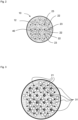
- Fig. 2 shows, in a horizontal section, initially only the arrangement of the plasma electrodes 21 in the reaction chamber 12 of the reactor vessel 10. They are arranged in the bubble column 4, with the anodes 21 and the cathodes 22 alternating in each row and each line, thus forming a checkerboard-like arrangement.
- Fig. 3 shows in addition to Fig. 2 also the arrangement of the ceramic immersion tubes 31. They are each arranged in a diagonal offset in the spaces spanned by the plasma electrodes 21 and are located in an electrically neutral zone due to the arrangement of the polarities of the plasma electrodes.
Landscapes
- Chemical & Material Sciences (AREA)
- Organic Chemistry (AREA)
- Inorganic Chemistry (AREA)
- General Health & Medical Sciences (AREA)
- Health & Medical Sciences (AREA)
- Chemical Kinetics & Catalysis (AREA)
- Engineering & Computer Science (AREA)
- Toxicology (AREA)
- Analytical Chemistry (AREA)
- Physics & Mathematics (AREA)
- Electromagnetism (AREA)
- Mechanical Engineering (AREA)
- Combustion & Propulsion (AREA)
- Organic Low-Molecular-Weight Compounds And Preparation Thereof (AREA)
Applications Claiming Priority (1)
| Application Number | Priority Date | Filing Date | Title |
|---|---|---|---|
| DE102022001148.4A DE102022001148A1 (de) | 2022-04-04 | 2022-04-04 | Vorrichtung und Verfahren zur Herstellung eines Alkohol-Synthesegases |
Publications (3)
| Publication Number | Publication Date |
|---|---|
| EP4257544A2 EP4257544A2 (de) | 2023-10-11 |
| EP4257544A3 EP4257544A3 (de) | 2023-11-15 |
| EP4257544B1 true EP4257544B1 (de) | 2025-03-12 |
Family
ID=85795328
Family Applications (1)
| Application Number | Title | Priority Date | Filing Date |
|---|---|---|---|
| EP23000050.7A Active EP4257544B1 (de) | 2022-04-04 | 2023-03-28 | Vorrichtung und verfahren zur herstellung eines alkohol-synthesegases |
Country Status (6)
| Country | Link |
|---|---|
| EP (1) | EP4257544B1 (pl) |
| DE (1) | DE102022001148A1 (pl) |
| DK (1) | DK4257544T3 (pl) |
| ES (1) | ES3030320T3 (pl) |
| FI (1) | FI4257544T3 (pl) |
| PL (1) | PL4257544T3 (pl) |
Families Citing this family (1)
| Publication number | Priority date | Publication date | Assignee | Title |
|---|---|---|---|---|
| WO2025056102A1 (de) * | 2023-09-14 | 2025-03-20 | EurA AG | Vorrichtung und verfahren zur herstellung eines alkohol-synthesegases |
Family Cites Families (7)
| Publication number | Priority date | Publication date | Assignee | Title |
|---|---|---|---|---|
| JP2003062579A (ja) * | 2001-08-27 | 2003-03-04 | Kobe Steel Ltd | 液体の処理方法及びその装置 |
| AUPS220302A0 (en) * | 2002-05-08 | 2002-06-06 | Chang, Chak Man Thomas | A plasma formed within bubbles in an aqueous medium and uses therefore |
| DE102006012313A1 (de) | 2006-03-17 | 2007-10-04 | Müller, Bernd | Rückführung von CO2 Emissionen zu einem Kraftstoff mit Hilfe von Festelektrolyten |
| DE102012010542A1 (de) | 2011-12-20 | 2013-06-20 | CCP Technology GmbH | Verfahren und anlage zur erzeugung von synthesegas |
| US9315735B2 (en) | 2013-03-15 | 2016-04-19 | Renewable Opportunities Inc. | System and method for producing a consistent quality syngas from diverse waste materials with heat recovery based power generation, and renewable hydrogen co-production |
| PL3498665T3 (pl) | 2017-12-18 | 2021-04-06 | Clariant International Ltd | Sposób otrzymywania gazu syntezowego |
| WO2022056456A1 (en) | 2020-09-14 | 2022-03-17 | Solena Group, Llc | Methods, processes and systems for the production of hydrogen from waste, biogenic waste and biomass |
-
2022
- 2022-04-04 DE DE102022001148.4A patent/DE102022001148A1/de active Pending
-
2023
- 2023-03-28 DK DK23000050.7T patent/DK4257544T3/da active
- 2023-03-28 ES ES23000050T patent/ES3030320T3/es active Active
- 2023-03-28 PL PL23000050.7T patent/PL4257544T3/pl unknown
- 2023-03-28 EP EP23000050.7A patent/EP4257544B1/de active Active
- 2023-03-28 FI FIEP23000050.7T patent/FI4257544T3/fi active
Also Published As
| Publication number | Publication date |
|---|---|
| DK4257544T3 (da) | 2025-05-26 |
| ES3030320T3 (en) | 2025-06-27 |
| DE102022001148A1 (de) | 2023-10-05 |
| EP4257544A3 (de) | 2023-11-15 |
| PL4257544T3 (pl) | 2025-07-07 |
| EP4257544A2 (de) | 2023-10-11 |
| FI4257544T3 (fi) | 2025-06-10 |
Similar Documents
| Publication | Publication Date | Title |
|---|---|---|
| DE69107992T2 (de) | Verfahren zur elektrolytischen Herstellung von Ozon und Vorrichtung dazu. | |
| DE102015201132A1 (de) | Verfahren und Elektrolysesystem zur Kohlenstoffdioxid-Verwertung | |
| DE112013004853T5 (de) | Wasserstofferzeugungsvorrichtung und Brennstoffzellensystem mit Wasserstofferzeugungsvorrichtung | |
| DE102017126886B3 (de) | Verfahren und Vorrichtung zur plasmainduzierten Wasserspaltung | |
| DE102018210303A1 (de) | Elektrochemische Niedertemperatur Reverse-Watergas-Shift Reaktion | |
| DE102016207420A1 (de) | Vorrichtung und Verfahren zur Herstellung eines Produktgases, insbesondere Synthesegases | |
| EP4257544B1 (de) | Vorrichtung und verfahren zur herstellung eines alkohol-synthesegases | |
| DE69006462T2 (de) | Verfahren zur Abwasserbehandlung mit hochkonzentriertem Ozonwasser. | |
| DE102017212278A1 (de) | CO2-Elektrolyseur | |
| DE102016218235A1 (de) | Verfahren zur Herstellung von Propanol, Propionaldehyd und/oder Propionsäure aus Kohlendioxid, Wasser und elektrischer Energie | |
| EP4010514A1 (de) | Elektrolyseur und verfahren zur kohlenstoffdioxidreduktion | |
| WO2021089183A1 (de) | Verfahren und anlage zur herstellung von monoethylenglycol | |
| DE102010049792B4 (de) | Kleinkraftwerk sowie Verfahren und Vorrichtung zur Gewinnung von hochreinem Wasserstoff | |
| WO2025056102A1 (de) | Vorrichtung und verfahren zur herstellung eines alkohol-synthesegases | |
| DE112011105521T5 (de) | Vorrichtung zum Aufbereiten von Wasserstoff und Verfahren zum Verwenden derselben | |
| DE102020208604B4 (de) | Energiewandlungssystem | |
| DE69806548T2 (de) | Elektrokatalytische methode zur sauerstoffentfernung aus meerwasser | |
| DE2125741B2 (de) | Verfahren zur Reinigung von Abwässern und Vorrichtung zur Durchführung dieses Verfahrens | |
| DE19910639A1 (de) | Reaktor für eine Flüssigkeitsbehandlungsanlage mit eingebauter Ozonerzeugung zur Begasung der Reaktorflüssigkeit | |
| DE4126349C2 (de) | Verfahren zur elektrolytischen Herstellung von Methanol und Methan durch Reduktion von Kohlendioxid | |
| WO2017167605A1 (de) | Vorrichtung und verfahren zur herstellung eines produktgases, insbesondere synthesegases | |
| EP3714084A1 (de) | Anlage zur elektrochemischen herstellung eines co-haltigen gasprodukts | |
| DE19927849A1 (de) | Verfahren und Vorrichtung zur Herstellung von Reinstwasser | |
| DE102021110695B3 (de) | Vorrichtung und Verfahren zur elektrolytischen Erzeugung von Ozon | |
| DE102019216601A1 (de) | Elektrolyseur zur Kohlenstoffdioxidreduktion |
Legal Events
| Date | Code | Title | Description |
|---|---|---|---|
| PUAI | Public reference made under article 153(3) epc to a published international application that has entered the european phase |
Free format text: ORIGINAL CODE: 0009012 |
|
| STAA | Information on the status of an ep patent application or granted ep patent |
Free format text: STATUS: THE APPLICATION HAS BEEN PUBLISHED |
|
| AK | Designated contracting states |
Kind code of ref document: A2 Designated state(s): AL AT BE BG CH CY CZ DE DK EE ES FI FR GB GR HR HU IE IS IT LI LT LU LV MC ME MK MT NL NO PL PT RO RS SE SI SK SM TR |
|
| PUAL | Search report despatched |
Free format text: ORIGINAL CODE: 0009013 |
|
| AK | Designated contracting states |
Kind code of ref document: A3 Designated state(s): AL AT BE BG CH CY CZ DE DK EE ES FI FR GB GR HR HU IE IS IT LI LT LU LV MC ME MK MT NL NO PL PT RO RS SE SI SK SM TR |
|
| RIC1 | Information provided on ipc code assigned before grant |
Ipc: C25B 1/04 20210101ALI20231010BHEP Ipc: C01B 13/02 20060101ALI20231010BHEP Ipc: C01B 3/34 20060101AFI20231010BHEP |
|
| STAA | Information on the status of an ep patent application or granted ep patent |
Free format text: STATUS: REQUEST FOR EXAMINATION WAS MADE |
|
| 17P | Request for examination filed |
Effective date: 20240515 |
|
| RBV | Designated contracting states (corrected) |
Designated state(s): AL AT BE BG CH CY CZ DE DK EE ES FI FR GB GR HR HU IE IS IT LI LT LU LV MC ME MK MT NL NO PL PT RO RS SE SI SK SM TR |
|
| GRAP | Despatch of communication of intention to grant a patent |
Free format text: ORIGINAL CODE: EPIDOSNIGR1 |
|
| STAA | Information on the status of an ep patent application or granted ep patent |
Free format text: STATUS: GRANT OF PATENT IS INTENDED |
|
| RIC1 | Information provided on ipc code assigned before grant |
Ipc: B01J 19/08 20060101ALN20241029BHEP Ipc: C01B 13/02 20060101ALI20241029BHEP Ipc: C01B 3/34 20060101AFI20241029BHEP |
|
| INTG | Intention to grant announced |
Effective date: 20241113 |
|
| RIN1 | Information on inventor provided before grant (corrected) |
Inventor name: SCHMIDT, DIRK Inventor name: KLIEMKE, HARDY |
|
| GRAS | Grant fee paid |
Free format text: ORIGINAL CODE: EPIDOSNIGR3 |
|
| GRAA | (expected) grant |
Free format text: ORIGINAL CODE: 0009210 |
|
| STAA | Information on the status of an ep patent application or granted ep patent |
Free format text: STATUS: THE PATENT HAS BEEN GRANTED |
|
| AK | Designated contracting states |
Kind code of ref document: B1 Designated state(s): AL AT BE BG CH CY CZ DE DK EE ES FI FR GB GR HR HU IE IS IT LI LT LU LV MC ME MK MT NL NO PL PT RO RS SE SI SK SM TR |
|
| REG | Reference to a national code |
Ref country code: GB Ref legal event code: FG4D Free format text: NOT ENGLISH |
|
| REG | Reference to a national code |
Ref country code: CH Ref legal event code: EP |
|
| REG | Reference to a national code |
Ref country code: DE Ref legal event code: R096 Ref document number: 502023000658 Country of ref document: DE |
|
| REG | Reference to a national code |
Ref country code: IE Ref legal event code: FG4D Free format text: LANGUAGE OF EP DOCUMENT: GERMAN |
|
| REG | Reference to a national code |
Ref country code: NL Ref legal event code: FP |
|
| REG | Reference to a national code |
Ref country code: DK Ref legal event code: T3 Effective date: 20250521 |
|
| REG | Reference to a national code |
Ref country code: FI Ref legal event code: FGE Ref country code: SE Ref legal event code: TRGR |
|
| REG | Reference to a national code |
Ref country code: ES Ref legal event code: FG2A Ref document number: 3030320 Country of ref document: ES Kind code of ref document: T3 Effective date: 20250627 |
|
| PG25 | Lapsed in a contracting state [announced via postgrant information from national office to epo] |
Ref country code: RS Free format text: LAPSE BECAUSE OF FAILURE TO SUBMIT A TRANSLATION OF THE DESCRIPTION OR TO PAY THE FEE WITHIN THE PRESCRIBED TIME-LIMIT Effective date: 20250612 |
|
| PGFP | Annual fee paid to national office [announced via postgrant information from national office to epo] |
Ref country code: MC Payment date: 20250626 Year of fee payment: 3 |
|
| PGFP | Annual fee paid to national office [announced via postgrant information from national office to epo] |
Ref country code: FI Payment date: 20250523 Year of fee payment: 3 |
|
| PGFP | Annual fee paid to national office [announced via postgrant information from national office to epo] |
Ref country code: PL Payment date: 20250429 Year of fee payment: 3 Ref country code: DE Payment date: 20250508 Year of fee payment: 3 |
|
| PGFP | Annual fee paid to national office [announced via postgrant information from national office to epo] |
Ref country code: ES Payment date: 20250522 Year of fee payment: 3 Ref country code: DK Payment date: 20250602 Year of fee payment: 3 |
|
| REG | Reference to a national code |
Ref country code: LT Ref legal event code: MG9D |
|
| PGFP | Annual fee paid to national office [announced via postgrant information from national office to epo] |
Ref country code: NO Payment date: 20250507 Year of fee payment: 3 |
|
| PGFP | Annual fee paid to national office [announced via postgrant information from national office to epo] |
Ref country code: BE Payment date: 20250507 Year of fee payment: 3 Ref country code: IT Payment date: 20250331 Year of fee payment: 3 |
|
| PG25 | Lapsed in a contracting state [announced via postgrant information from national office to epo] |
Ref country code: HR Free format text: LAPSE BECAUSE OF FAILURE TO SUBMIT A TRANSLATION OF THE DESCRIPTION OR TO PAY THE FEE WITHIN THE PRESCRIBED TIME-LIMIT Effective date: 20250312 |
|
| PG25 | Lapsed in a contracting state [announced via postgrant information from national office to epo] |
Ref country code: LV Free format text: LAPSE BECAUSE OF FAILURE TO SUBMIT A TRANSLATION OF THE DESCRIPTION OR TO PAY THE FEE WITHIN THE PRESCRIBED TIME-LIMIT Effective date: 20250312 |
|
| PGFP | Annual fee paid to national office [announced via postgrant information from national office to epo] |
Ref country code: FR Payment date: 20250422 Year of fee payment: 3 |
|
| PG25 | Lapsed in a contracting state [announced via postgrant information from national office to epo] |
Ref country code: GR Free format text: LAPSE BECAUSE OF FAILURE TO SUBMIT A TRANSLATION OF THE DESCRIPTION OR TO PAY THE FEE WITHIN THE PRESCRIBED TIME-LIMIT Effective date: 20250613 Ref country code: BG Free format text: LAPSE BECAUSE OF FAILURE TO SUBMIT A TRANSLATION OF THE DESCRIPTION OR TO PAY THE FEE WITHIN THE PRESCRIBED TIME-LIMIT Effective date: 20250312 |
|
| PGFP | Annual fee paid to national office [announced via postgrant information from national office to epo] |
Ref country code: TR Payment date: 20250603 Year of fee payment: 3 |
|
| PGFP | Annual fee paid to national office [announced via postgrant information from national office to epo] |
Ref country code: SE Payment date: 20250429 Year of fee payment: 3 |
|
| PG25 | Lapsed in a contracting state [announced via postgrant information from national office to epo] |
Ref country code: SM Free format text: LAPSE BECAUSE OF FAILURE TO SUBMIT A TRANSLATION OF THE DESCRIPTION OR TO PAY THE FEE WITHIN THE PRESCRIBED TIME-LIMIT Effective date: 20250312 |
|
| PG25 | Lapsed in a contracting state [announced via postgrant information from national office to epo] |
Ref country code: PT Free format text: LAPSE BECAUSE OF FAILURE TO SUBMIT A TRANSLATION OF THE DESCRIPTION OR TO PAY THE FEE WITHIN THE PRESCRIBED TIME-LIMIT Effective date: 20250714 |
|
| REG | Reference to a national code |
Ref country code: DE Ref legal event code: R082 Ref document number: 502023000658 Country of ref document: DE Representative=s name: WEIHRAUCH, FRANK, DR., DE |
|
| PG25 | Lapsed in a contracting state [announced via postgrant information from national office to epo] |
Ref country code: CZ Free format text: LAPSE BECAUSE OF FAILURE TO SUBMIT A TRANSLATION OF THE DESCRIPTION OR TO PAY THE FEE WITHIN THE PRESCRIBED TIME-LIMIT Effective date: 20250312 Ref country code: EE Free format text: LAPSE BECAUSE OF FAILURE TO SUBMIT A TRANSLATION OF THE DESCRIPTION OR TO PAY THE FEE WITHIN THE PRESCRIBED TIME-LIMIT Effective date: 20250312 |
|
| PG25 | Lapsed in a contracting state [announced via postgrant information from national office to epo] |
Ref country code: RO Free format text: LAPSE BECAUSE OF FAILURE TO SUBMIT A TRANSLATION OF THE DESCRIPTION OR TO PAY THE FEE WITHIN THE PRESCRIBED TIME-LIMIT Effective date: 20250312 |
|
| PG25 | Lapsed in a contracting state [announced via postgrant information from national office to epo] |
Ref country code: SK Free format text: LAPSE BECAUSE OF FAILURE TO SUBMIT A TRANSLATION OF THE DESCRIPTION OR TO PAY THE FEE WITHIN THE PRESCRIBED TIME-LIMIT Effective date: 20250312 |
|
| PG25 | Lapsed in a contracting state [announced via postgrant information from national office to epo] |
Ref country code: IS Free format text: LAPSE BECAUSE OF FAILURE TO SUBMIT A TRANSLATION OF THE DESCRIPTION OR TO PAY THE FEE WITHIN THE PRESCRIBED TIME-LIMIT Effective date: 20250712 |
|
| PG25 | Lapsed in a contracting state [announced via postgrant information from national office to epo] |
Ref country code: LU Free format text: LAPSE BECAUSE OF NON-PAYMENT OF DUE FEES Effective date: 20250328 |
|
| REG | Reference to a national code |
Ref country code: DE Ref legal event code: R097 Ref document number: 502023000658 Country of ref document: DE |
|
| PLBE | No opposition filed within time limit |
Free format text: ORIGINAL CODE: 0009261 |
|
| STAA | Information on the status of an ep patent application or granted ep patent |
Free format text: STATUS: NO OPPOSITION FILED WITHIN TIME LIMIT |
|
| PG25 | Lapsed in a contracting state [announced via postgrant information from national office to epo] |
Ref country code: IE Free format text: LAPSE BECAUSE OF NON-PAYMENT OF DUE FEES Effective date: 20250328 |
|
| REG | Reference to a national code |
Ref country code: CH Ref legal event code: L10 Free format text: ST27 STATUS EVENT CODE: U-0-0-L10-L00 (AS PROVIDED BY THE NATIONAL OFFICE) Effective date: 20260121 |
|
| 26N | No opposition filed |
Effective date: 20251215 |
|
| PGFP | Annual fee paid to national office [announced via postgrant information from national office to epo] |
Ref country code: AT Payment date: 20260301 Year of fee payment: 4 |