EP4255641B1 - Installation de revêtement et procédé de fonctionnement associé présentant une simulation de la quantité d'agent de revêtement nécessaire - Google Patents
Installation de revêtement et procédé de fonctionnement associé présentant une simulation de la quantité d'agent de revêtement nécessaire Download PDFInfo
- Publication number
- EP4255641B1 EP4255641B1 EP23712485.4A EP23712485A EP4255641B1 EP 4255641 B1 EP4255641 B1 EP 4255641B1 EP 23712485 A EP23712485 A EP 23712485A EP 4255641 B1 EP4255641 B1 EP 4255641B1
- Authority
- EP
- European Patent Office
- Prior art keywords
- pig
- coating
- station
- coating agent
- component
- Prior art date
- Legal status (The legal status is an assumption and is not a legal conclusion. Google has not performed a legal analysis and makes no representation as to the accuracy of the status listed.)
- Active
Links
- 239000011248 coating agent Substances 0.000 title claims description 194
- 238000000576 coating method Methods 0.000 title claims description 89
- 238000004088 simulation Methods 0.000 title claims description 32
- 238000011017 operating method Methods 0.000 title claims description 13
- 238000009434 installation Methods 0.000 title claims 14
- 239000003973 paint Substances 0.000 claims description 147
- 238000010422 painting Methods 0.000 claims description 29
- 241000282887 Suidae Species 0.000 claims description 6
- 230000001419 dependent effect Effects 0.000 claims description 6
- 238000004519 manufacturing process Methods 0.000 claims description 4
- 239000000853 adhesive Substances 0.000 claims description 2
- 230000001070 adhesive effect Effects 0.000 claims description 2
- 230000004888 barrier function Effects 0.000 claims description 2
- 238000011156 evaluation Methods 0.000 claims description 2
- 230000006870 function Effects 0.000 claims description 2
- 230000001939 inductive effect Effects 0.000 claims description 2
- 239000011810 insulating material Substances 0.000 claims description 2
- 239000011159 matrix material Substances 0.000 claims description 2
- 238000011144 upstream manufacturing Methods 0.000 claims description 2
- 238000003825 pressing Methods 0.000 claims 1
- 238000000034 method Methods 0.000 description 38
- 239000000314 lubricant Substances 0.000 description 22
- 239000003999 initiator Substances 0.000 description 9
- 238000002156 mixing Methods 0.000 description 5
- 238000007591 painting process Methods 0.000 description 5
- 238000011010 flushing procedure Methods 0.000 description 4
- 230000032258 transport Effects 0.000 description 3
- 238000004891 communication Methods 0.000 description 2
- 238000004364 calculation method Methods 0.000 description 1
- 238000011109 contamination Methods 0.000 description 1
- 238000011161 development Methods 0.000 description 1
- 230000018109 developmental process Effects 0.000 description 1
- 230000000694 effects Effects 0.000 description 1
- 238000009503 electrostatic coating Methods 0.000 description 1
- 230000010354 integration Effects 0.000 description 1
- 238000012423 maintenance Methods 0.000 description 1
- 239000000565 sealant Substances 0.000 description 1
- 238000000926 separation method Methods 0.000 description 1
Images


Classifications
-
- B—PERFORMING OPERATIONS; TRANSPORTING
- B05—SPRAYING OR ATOMISING IN GENERAL; APPLYING FLUENT MATERIALS TO SURFACES, IN GENERAL
- B05B—SPRAYING APPARATUS; ATOMISING APPARATUS; NOZZLES
- B05B12/00—Arrangements for controlling delivery; Arrangements for controlling the spray area
- B05B12/08—Arrangements for controlling delivery; Arrangements for controlling the spray area responsive to condition of liquid or other fluent material to be discharged, of ambient medium or of target ; responsive to condition of spray devices or of supply means, e.g. pipes, pumps or their drive means
- B05B12/12—Arrangements for controlling delivery; Arrangements for controlling the spray area responsive to condition of liquid or other fluent material to be discharged, of ambient medium or of target ; responsive to condition of spray devices or of supply means, e.g. pipes, pumps or their drive means responsive to conditions of ambient medium or target, e.g. humidity, temperature position or movement of the target relative to the spray apparatus
- B05B12/122—Arrangements for controlling delivery; Arrangements for controlling the spray area responsive to condition of liquid or other fluent material to be discharged, of ambient medium or of target ; responsive to condition of spray devices or of supply means, e.g. pipes, pumps or their drive means responsive to conditions of ambient medium or target, e.g. humidity, temperature position or movement of the target relative to the spray apparatus responsive to presence or shape of target
-
- B—PERFORMING OPERATIONS; TRANSPORTING
- B05—SPRAYING OR ATOMISING IN GENERAL; APPLYING FLUENT MATERIALS TO SURFACES, IN GENERAL
- B05B—SPRAYING APPARATUS; ATOMISING APPARATUS; NOZZLES
- B05B12/00—Arrangements for controlling delivery; Arrangements for controlling the spray area
- B05B12/14—Arrangements for controlling delivery; Arrangements for controlling the spray area for supplying a selected one of a plurality of liquids or other fluent materials or several in selected proportions to a spray apparatus, e.g. to a single spray outlet
- B05B12/1481—Arrangements for controlling delivery; Arrangements for controlling the spray area for supplying a selected one of a plurality of liquids or other fluent materials or several in selected proportions to a spray apparatus, e.g. to a single spray outlet comprising pigs, i.e. movable elements sealingly received in supply pipes, for separating different fluids, e.g. liquid coating materials from solvent or air
Definitions
- the invention relates to a coating system for coating components with a coating agent, in particular for painting motor vehicle body components with a paint.
- the invention also relates to a corresponding operating method for such a coating system.
- rotary atomizers guided by painting robots are usually used as application devices.
- the painting robots are arranged in a painting booth, with the vehicle body components to be painted being conveyed through the painting booth by a conveyor and then painted in the painting booth.
- the paint to be applied is provided by a paint supply device and conveyed through a pig line to the respective robot station in the paint booth.
- the required amount of paint is first determined, which depends on the component type of the vehicle body to be painted and also on the type of paint to be applied.
- the required amount of paint is then filled into the pig line by the paint supply device at a pig source station and conveyed by a pig package along the pig line to a pig target station at the respective robot station.
- the paint is then removed from the pig package and used to paint the respective vehicle body.
- the paint remaining in the pig package is then conveyed along the pig line back to the pig source station as part of a so-called reflow process.
- the so-called reflow paint can then be removed from the pig package again, which enables the paint to be recycled.
- the problem with such painting systems is determining the required amount of paint that is filled into the pig package and transported through the pig line to the robot station. It has already been mentioned above that the amount of paint required depends on the component type and the type of paint. However, due to the large number of component types used and the equally large number of paint types used, it is hardly possible to have the required amount of paint available in an allocation table for all combinations of component types and paint types. During ongoing painting operations, a great deal of maintenance is therefore required to keep these allocation tables up to date, for example if a new paint type or a new component type has to be added.
- the technical background of the invention also includes EP 1 837 726 A1 , EP 1 270 083 A1 , US 2006/0 086 407 A1 , EP 1 380 350 A1 , DE 101 20 272 A1 , DE 198 30 029 A1 , US 6 936 106 B2 , EN 10 2015 006 666 A1 , JP 2002 172 350 A , EN 10 2004 046 351 A1 and DE 101 36 328 A1 .
- the invention is therefore based on the object of solving the above-described problem of to determine the exact amount of coating agent required depending on the type of coating agent and the component type.
- the invention comprises the general technical teaching of determining the amount of coating agent required for coating a component as a function of the respective coating agent type and the respective component type within the framework of a simulation, as will be explained in detail below.
- the coating system according to the invention initially has, in accordance with the known coating system described at the outset, at least one coating station (e.g. paint booth) with a robot station in which a coating robot is arranged in order to coat the components with the coating agent.
- at least one coating station e.g. paint booth
- robot station in which a coating robot is arranged in order to coat the components with the coating agent.
- the coating station is a paint booth that has largely closed booth walls except for the inlet and/or outlet.
- the invention is not limited to a largely closed paint booth, but can also be implemented, for example, with coating stations that are only functionally closed, but not spatially closed.
- the invention is not limited to motor vehicle body components with regard to the components to be coated. Rather, the inventive concept is also suitable for coating other types of components.
- the invention is not limited to paint with regard to the coating agent to be applied.
- the coating agent can also be an adhesive, an insulating material or a sealant, to name just a few examples.
- the coating robot uses a rotary atomizer as the application device.
- the invention is also Application devices are not limited to rotary atomizers.
- air atomizers or so-called print heads which are known from the state of the art, can also be used as application devices.
- the coating system according to the invention in accordance with the known coating system described at the beginning, has a conveyor for conveying the components to be coated into the coating station and for conveying them out of the coating station again.
- Such conveyors are known per se from conventional painting systems for painting motor vehicle body components and therefore do not need to be described in more detail.
- the coating system according to the invention in accordance with the known coating system described at the outset, has an information source which provides a component identifier which is assigned to the component conveyed into the coating station, wherein the component identifier respectively indicates the component type of the component conveyed into the coating station by the conveyor and the coating agent type of the coating agent to be applied to the respective component.
- this information source is a reading point that is arranged upstream of the coating station with respect to the conveyor, in particular at the inlet of the coating station, as is known per se from conventional painting systems for painting motor vehicle body components.
- This reading point can then read the component identifier attached to the component or to a component carrier ("skid"), with this reading process preferably taking place wirelessly.
- this reading process can take place using RFID (RFID: radio-frequency identification), using a barcode, using a light barrier matrix or using an inductive sensor solution, to name just a few examples.
- RFID radio-frequency identification
- the information source for providing the component identifier assigned to the component being fed in is a production control system.
- the production control system of a paint shop knows the component type of the vehicle body component being fed in and also the type of paint to be applied. In this case, no real reading point is required, since the production control system provides a virtual reading point.
- the coating system according to the invention in accordance with the known coating system described at the outset, has a paint supply device in order to provide the coating agent to be applied with a specific amount of coating agent that is required for coating the respective component according to the respective component type and the respective coating agent type.
- this paint supply device is usually arranged in a so-called paint mixing room, which is located spatially away from the paint booth.
- the coating system according to the invention also has a pig source station at the paint supply device and a pig target station at the respective robot station in the coating station, wherein the pig source station is connected to the pig target station by a pig line in order to convey the amount of coating agent required for coating the component at the robot station from the paint supply device through the pig line to the robot station.
- the paint supply device is controlled by a paint supply control system, which specifies the required amount of coating agent, which is then filled into the pig line at the pig source station.
- the invention is distinguished from the known coating system described at the beginning in that a simulation computer is provided which simulates a coating process for the respective component.
- the simulation computer takes into account the component identifier provided by the information source with the component type and the coating agent type.
- the simulation computer calculates the amount of coating agent required for coating, taking into account the component type and the coating agent type, and makes the value of the required amount of coating agent determined during the simulation available to the paint supply control.
- the paint supply control then controls the paint supply device so that exactly the previously determined required amount of coating agent is filled into the pig line. It should be mentioned here that in addition to the required amount of coating agent, a reflow amount can also be filled into the pig package, whereby the reflow amount ensures that the pig package is not moved back dry during a reflow process.
- the paint supply control can have a paint quantity memory in which the required standard quantity is stored for different component types and different coating agent types. If there is a disruption in the reception of the required coating agent quantity from the simulation computer, the paint supply control can then read the standard quantity corresponding to the component type and the coating agent type from the paint quantity memory, so that the pig source station then fills the pig line with the read standard quantity. If there is a disruption in communication between the simulation computer and the paint supply control, the coating system according to the invention can therefore work in a similar way to the known coating agent system described at the beginning, in which the allocation table with the allocation between component type and coating agent type on the one hand and the required coating agent quantity on the other hand has to be laboriously maintained.
- the required amount of coating agent is conveyed from the pig source station at the paint supply device to the pig target station at the robot station.
- the required amount of coating agent is filled into a pig package in the pig line, whereby the pig package comprises two pigs that convey the required amount of coating agent between themselves.
- the pig source station then transports the pig package filled with the required amount of coating agent along the pig line to the pig target station, where the required amount of coating agent can be removed from the pig package.
- a certain amount of coating agent usually remains in the pig package, which is available for a so-called reflow process.
- the pig package is transported back from the pig target station to the pig source station with a certain amount of the coating agent contained therein.
- This backward movement of the pig package should not take place empty, i.e. without the pig package being filled with coating agent, as the friction of the pig package in the pig line also depends on the amount of coating agent in the pig package.
- the backward movement of the pig package during the reflow process should not take place with the pig package being filled with too much coating agent.
- the pig package should therefore be filled with a precisely defined amount of coating agent if possible, as the amount of coating agent also influences the speed of movement of the pig package during the backward movement to the pig source station. If the pig package moves too quickly during the reflow process, this can damage the pigs. On the other hand, if the movement speed of the pig package during the reflow process is too low, this costs cycle time, i.e. the entire process is slowed down.
- the calculation of the required amount of coating agent according to the invention now makes it possible for the amount of coating agent remaining in the pig package during the reflow process to be almost constant, which also leads to a correspondingly constant movement speed of the pig package during the reflow process.
- the return speed of the pig package during the return from the pig target station to the pig source station can therefore be largely independent of the type of coating agent and the type of component, whereby the type-dependent deviations can be limited to a maximum of 30%, 90%, 10% or even 5%.
- the movement of the pig package between the pig source station and the pig destination station can in the conventional manner by introducing compressed air into the pig line in order to push the pig package to the pig source station or to the pig target station.
- the robot station can have a station control that controls the operation of the robot station.
- the above-mentioned simulation computer according to the invention can then be integrated either into the station control or into the paint supply control.
- the invention also includes a corresponding operating method for such a coating system.
- the individual process steps of the operating method according to the invention are already apparent from the above description of the coating system according to the invention, so that a separate description of the individual process steps can be dispensed with.
- the paint supply system has a pig source station 1, which is supplied with paint via several paint connections QFa-QFd.
- the pig source station 1 is connected via a pig line 2 to a pig target station 3, which forwards the paint to be applied via a connection ZF to the rotary atomizer (not shown).
- a lubricant valve 4 is arranged in the pig line 2, which will be described in more detail. At this point, it should only be mentioned briefly that the lubricant valve 4 is intended to introduce lubricant into the pig line 2 in order to reduce the friction in the pig line 2.
- a movable pig package in the pig line 2 which consists of two pigs, namely a pushout pig 5 and a reflow pig 6.
- a paint column 7 can be clamped between the pushout pig 5 and the reflow pig 6, which is transported from the pig source station 1 to the pig target station 3 in a pushout process and in the opposite direction from the pig target station 3 to the pig source station 1 in a reflow process.
- the movement of the pig package from the pig source station 1 to the pig target station 3 takes place in a pushout process by introducing a pushing medium (e.g. compressed air) into the pig line 2 at the pig source station 1 via a QMS connection, whereby the pushing medium then transports the pig package with the pushout pig 5 and the reflow pig 6 along the pig line 2 to the pig target station 3.
- a pushing medium e.g. compressed air
- a pushing medium e.g. compressed air
- the paint column 7 returned to the pig source station 1 can then be returned to the paint connections QFa-QFd in order to enable reuse.
- the pig package with the pushout pig 5 and the reflow pig 6 and the paint column 7 clamped between them moves in the otherwise dry pig line 2, i.e. the pig line 2 is empty between the pushout pig 5 and the pig source station 1.
- the invention therefore provides that during a reflow process, a lubricant is fed into the pig line 2 between the push-out pig 5 and the pig source station 1, wherein the lubricant then forms a lubricant column 8 in the pig line 2, which during the reflow process is located in front of the push-out pig 5 with respect to the direction of movement of the push-out pig 5.
- This reduces the friction of the push-out pig 5 during the reflow process in the otherwise empty pig line 2, which enables a greater movement speed of the pig package during the reflow process.
- the lubricant is introduced into the pig line 2 through the lubricant valve 4 mentioned above, which is arranged in the pig line 2.
- the lubricant is introduced into the pig line 2
- it must be prevented that the lubricant is fed into the paint column 7, which is clamped in the pig package between the push-out pig 5 and the reflow pig 6. This would lead to contamination of the paint in the paint column 7, which would prevent the paint from being reused.
- the paint supply according to the invention therefore has a sensor 9 which is arranged on the pig line 2 near the pig target station 3 and detects the filling state of the pig line 2.
- a sensor 9 which is arranged on the pig line 2 near the pig target station 3 and detects the filling state of the pig line 2.
- the position of the lubricant valve 4 is important here, and should be as close as possible to the pig target station 3 so that the pushout pig 5 is lubricated as far as possible during its entire backward movement from the pig target station 3 to the pig source station 1 as part of the reflow process.
- the distance between the lubricant valve 4 and the pig target station 3 along the pig line can therefore be less than 10 cm, for example.
- the position of the sensor 9 along the pig line 2 is important.
- the sensor 9 and its measuring point should be as close as possible to the lubricant feed point of the lubricant valve 4. This is important so that the sensor 9 can then detect the filling state of the pig line 2 at the lubricant feed point of the lubricant valve 4.
- the pig source station 1 is at an electrical ground potential during operation.
- the pig target station 3 can be set to either ground potential or high-voltage potential in order to enable electrostatic coating agent charging.
- the pig line 2 is completely emptied and cleaned in order to form the greatest possible electrical resistance, which enables potential separation between the pig source station 1 on the one hand and the pig target station 3 on the other.
- Figure 2 described which include the integration of the above described and in Figure 1 shows the pigging system in a painting plant.
- the painting system has a painting booth 12, wherein a conveyor 13 conveys the motor vehicle bodies 14 to be painted through the painting booth 12 in the direction of the arrow, as is only schematically indicated by an arrow in the drawing.
- the pig target station 3 is located in the paint booth 12 and is used to supply paint to a Painting robot 15.
- the drawing shows a paint mixing room 16 with the pig source station 1 arranged therein.
- FIG. 1 shows that the already Figure 1
- the control unit 11 shown controls the pig source station 1 so that the pig source station 1 fills the required amount of paint into a pig package 17, which consists of the push-out pig 5 and the reflow pig 6.
- the required amount of paint is determined by a simulation computer 18 as part of a simulation of the painting process.
- the simulation computer 18 takes into account the type of motor vehicle body 14 to be painted and also the type of paint to be applied, since both variables (paint type and body type) influence the required amount of paint.
- the painting system has a reading point 19, which is arranged at the inlet of the painting booth 12 and reads a component identifier on the incoming motor vehicle body 14.
- This reading process can be carried out, for example, using an RFID transponder on the motor vehicle body 14 or by reading a barcode on the motor vehicle body 14.
- the read component identifier contains the component type of the motor vehicle body 14 and the type of paint to be applied.
- This information is transmitted from the reading point 19 to the simulation computer 18, which then simulates the actual painting process and determines the required amount of paint. This value is then transferred to the control unit 11 for the paint mixing room 16.
- the control unit 11 then controls the pig source station 1 so that the required amount of paint is filled into the pig line 2.
- the control unit 11 then also controls the pig source station 1 so that the pig package 17 with the amount of paint filled into it is conveyed to the pig target station 3.
- compressed air is introduced into the pig line 2 at the pig source station 1 behind the pig package 17, whereby the compressed air then pushes the pig package 17 to the pig target station 3.
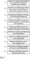
- a first step S1 the paint type and the type of motor vehicle body 14 to be painted are first read out at the reading point 19.
- step S2 the painting process is simulated according to the paint type and the body type, whereby the required amount of paint is determined during the simulation.
- the required amount of paint is then transmitted to the control unit 11 of the paint mixing room 16 in a step S3.
- the control unit 11 then controls the pig source station 1 in a step S4 so that the required amount of paint is filled into the pig package 17 in the pig line 2.
- the filled pig package 17 with the required amount of paint contained therein is then conveyed along the pig line 2 to the robot station with the pig target station 3.
- step S6 then provides that the paint is removed from the pig package 17 at the pig target station 3.
- the vehicle body 14 can then be painted with the removed paint at the robot station.
- step S8 of the pig package 17 After completion of the painting process, a so-called reflow takes place in step S8 of the pig package 17 with the remaining paint from the pig target station 3 back to the pig source station 1.
- the paint remaining in the pig package 17 can then be removed from the pig package 17, which takes place in a step S9.
- the paint removed during the reflow process can then either be disposed of or reused.
Claims (17)
- Installation de revêtement pour le revêtement de composants (14) avec un produit de revêtement, plus particulièrement pour la peinture de carrosseries de véhicules automobiles (14) avec une peinture, aveca) une station de revêtement (12) avec au moins une station robotique disposée dans la station de revêtement (12), dans laquelle la station robotique comprend un robot de revêtement (15) afin de revêtir les composants (14) avec le produit de revêtement,b) un convoyeur (13) pour l'introduction des composants (14) à revêtir dans la station de revêtement (12),c) une source d'informations (19) pour la mise à disposition d'un identifiant de composant, qui correspond au composant (14) introduit dans la station de revêtement (12), dans laquelle l'identifiant de composant indique respectivement le type de composant du composant (14) introduit par le convoyeur (13) dans la station de revêtement (12) et le type de produit de revêtement du produit de revêtement à appliquer sur le composant (14) respectif,d) un dispositif d'alimentation en peinture (16) pour la mise à disposition du produit de revêtement à appliquer avec une quantité de produit de revêtement déterminée, qui est nécessaire pour le revêtement du composant (14) respectif, en fonction du type de composant respectif et du type de produit de revêtement respectif,e) une station source de racleurs (1) sur le dispositif d'alimentation en peinture (16),f) une station cible de racleurs (3) au niveau de la station robotique dans la station de revêtement (12),g) une conduite à racleur (2), qui relie la station source de racleurs (1) et la station cible de racleurs (3), afin de transporter la quantité de produit de revêtement nécessaire pour le revêtement du composant (14) du dispositif d'alimentation en peinture (16) vers la station robotique en passant par la conduite à racleur (2) eth) une commande d'alimentation en peinture (11) pour le contrôle de la quantité de produit de revêtement qui est introduit du dispositif d'alimentation en peinture (16) au niveau de la station source de racleurs (1) vers la conduite à racleur (2) et qui est transportée par la conduite à racleur (2) vers la station cible de racleurs (3), caractérisée en ce quei) un calculateur de simulation (18) est prévu, qui simule un revêtement du composant (14) respectif,j) le calculateur de simulation (18) reçoit, de la part de la source d'informations (19), l'identifiant de composant avec le type de composant et le type de produit de revêtement correspondant au composant (14) respectif, qui est introduit par le convoyeur (13) dans la station de revêtement (12),k) le calculateur de simulation (18) calcule, à partir du type de composant et du type de produit de revêtement, grâce à la simulation du revêtement, la quantité de produit de revêtement nécessaire, qui est nécessaire au niveau de la station robotique pour le revêtement du composant (14) respectif etl) le calculateur de simulation (18) de la commande d'alimentation en peinture (11) transmet la quantité de produit de revêtement nécessaire, de sorte que la commande d'alimentation en peinture (11) introduit la quantité de produit de revêtement nécessaire avec la station source de racleurs (1) dans la conduite à racleur (2).
- Installation de revêtement selon la revendication 1, caractérisée en ce que la commande d'alimentation en peinture (11) définit, dans le cas d'une réception perturbée de la quantité de produit de revêtement nécessaire par le calculateur de simulation (18), une quantité standard pour la quantité de produit de revêtement nécessaire, de sorte que la station source de racleurs (1) remplit la conduite à racleur (2) avec la quantité standard.
- Installation de revêtement selon la revendication 1, caractérisée en ce quea) la commande d'alimentation en peinture (11) comprend une mémoire de quantité de peinture, dans laquelle est enregistrée la quantité standard nécessaire respectivement pour différents types de composants et différents types de produits de revêtement,b) la commande d'alimentation en peinture (11) lit, dans le cas d'une réception perturbée de la quantité de produit de revêtement nécessaire par le calculateur de simulation (18), la quantité standard dans la mémoire de quantité de peinture, de sorte que la station source de racleurs (1) remplit la conduite à racleur (2) avec la quantité standard.
- Installation de revêtement selon l'une des revendications précédentes, caractérisée en ce que le calculateur de simulation (18) enregistre, pour une analyse ultérieure, un ensemble de données correspondant respectivement à chacun des composants (14), qui contient les données suivantes :a) le type de composant du composant (14) à revêtir,b) le type de produit de revêtement du produit de revêtement à appliquer etc) la quantité de produit de revêtement nécessaire pour le revêtement du composant (14) au niveau de la station robotique, qui a été déterminée par le calculateur de simulation (18).
- Installation de revêtement selon l'une des revendications précédentes, caractérisée en ce quea) la station source de racleurs (1) introduit la quantité de produit de revêtement nécessaire dans un groupe de racleurs (17) dans la conduite à racleur (2), dans laquelle le groupe de racleurs (17) comprend deux racleurs (5, 6) qui emprisonnent la quantité de produit de revêtement nécessaire entre eux,b) la station source de racleurs (1) transporte le groupe de racleurs (17) rempli de la quantité de produit de revêtement nécessaire le long de la conduite à racleur (2) vers la station cible de racleurs (3) etc) la station cible de racleurs (3) prélève la quantité de produit de revêtement nécessaire dans le groupe de racleurs (17).
- Installation de revêtement selon la revendication 5, caractérisée en ce quea) la station cible de racleurs (3) transporte, après la fin du revêtement d'un composant, le groupe de racleurs (17), avec le produit de revêtement restant, avec une vitesse de retour déterminée, le long de la conduite à racleurs (2), à nouveau vers la station source de racleurs (1) etb) la station source de racleurs (1) prélève le produit de revêtement dans le groupe de racleurs (17) retourné pour une réutilisation ou pour une élimination.
- Installation de revêtement selon la revendication 6, caractérisée en ce quea) la quantité de produit de revêtement retourné est globalement constante indépendamment du type de produit de revêtement et indépendamment du type de composant, plus particulièrement avec des écarts en fonction du type de 30 %, 20 %, 10 % ou 5 % maximum et/oub) la vitesse de retour du groupe de racleurs (17) lors du retour du produit de revêtement de la station cible de racleurs (3) vers la station source de racleurs (1) est globalement constante indépendamment du type de produit de revêtement et indépendamment du type de composant, plus particulièrement avec des écarts en fonction du type de 30 %, 20 %, 10 % ou 5 % maximum.
- Installation de revêtement selon la revendication 6 ou 7, caractérisée en ce quea) la station source de racleurs (1) transporte le groupe de racleurs (17) vers la station cible de racleurs (3) grâce au fait que la station source de racleurs (1) introduit de l'air comprimé dans la conduite de racleurs (2), dans laquelle l'air comprimé pousse le groupe de racleurs (17) vers la station cible de racleurs (3) et/oub) la station cible de racleurs (3) transporte le groupe de racleurs (17) vers la station source de racleurs (1) grâce au fait que la station cible de racleurs (3) introduit de l'air comprimé dans la conduite de racleurs (2), dans laquelle l'air comprimé pousse le groupe de racleurs (17) vers la station source de racleurs (1).
- Installation de revêtement selon l'une des revendications précédentes, caractérisée en ce quea) la station robotique comprend une commande de station qui contrôle le fonctionnement de la station robotique etb) le calculateur de simulation (18) est intégré dans la commande de station ou dans la commande d'alimentation en peinture (11).
- Installation de revêtement selon l'une des revendications précédentes, caractérisée en ce quea) la station de revêtement (12) est une cabine de revêtement (12) qui est délimitée par des parois de cabine et/oub) la cabine de revêtement (12)b1) comprend une seule entrée afin d'introduire les composants (14) à travers l'entrée dans la cabine de revêtement (12) et de les évacuer de nouveau à travers l'entrée hors de la cabine de revêtement (12) oub2) comprend une entrée et une sortie, dans laquelle les composants (14) à revêtir sont introduits à travers l'entrée dans la cabine de revêtement (12) et sont évacués hors de la cabine de revêtement (12) à travers la sortie et/ouc) le produit de revêtement est une peinture, une colle ou un matériau isolant et/oud) les composants (14) à revêtir sont des composants de carrosseries de véhicules automobiles et/oue) le robot de revêtement (15), en tant qu'appareil d'application, contrôle un pulvérisateur rotatif, un pulvérisateur pneumatique ou une tête d'impression pour l'application de la peinture.
- Installation de revêtement selon l'une des revendications précédentes, caractérisée en ce quea) la source d'informations (19) pour la mise à disposition de l'identifiant de composant correspondant au composant (14) introduit, est un point de lecture (19) qui est disposé, par rapport au convoyeur (13), en amont de la station de revêtement (12), plus particulièrement à l'entrée de la station de revêtement (12), dans laquelle le point de lecture (19) lit l'identifiant de composant sur le composant (14) ou sur un support de composant, plus particulièrement sans fil, para1) RFIDa2) code barrea3) une matrice de barrière photo-électrique oua4) une solution de capteur inductif oub) la source d'informations (19) pour la mise à disposition de l'identifiant de composant correspondant au composant (14) est une commande de production.
- Procédé de fonctionnement pour une installation de revêtement de composants (14) avec un produit de revêtement, plus particulièrement pour une installation de revêtement selon l'une des revendications précédentes, avec les étapes suivantes :a) détermination d'un type de composant du composant (14) à revêtir,b) détermination d'un type de produit de revêtement du produit de revêtement à appliquer sur le composant (14),c) détermination de la quantité de produit de revêtement nécessaire au niveau d'une station robotique dans une station de revêtement (12), pour le revêtement du composant (14), en fonction du type de composant et du type de produit de revêtement,d) transport de la quantité de produit de revêtement nécessaire pour le revêtement du composant (14) à travers une conduite de racleurs (2) d'une station source de racleurs (1), au niveau d'un dispositif d'alimentation en peinture (16), vers une station cible de racleurs (3) au niveau de la station robotique,e) prélèvement de la quantité de produit de revêtement nécessaire dans la conduite de racleurs (2) au niveau de la station cible de racleurs (3) etf) revêtement du composant (14) avec la quantité de produit de revêtement nécessaire prélevée dans la conduite de racleurs (2),caractérisé par l'étape suivante pour la détermination de la quantité de produit de revêtement nécessaire :
g) simulation d'un processus de revêtement au moyen d'un calculateur de simulation (18) en fonction du type de composant du composant (14) à revêtir et du type de produit de revêtement du produit de revêtement à appliquer sur le composant (14). - Procédé de fonctionnement selon la revendication 12, caractérisé par les étapes suivantes :a) introduction du composant (14) à revêtir dans la station de revêtement (12)à au moyen d'un convoyeur (13) etb) lecture d'un identifiant de composant du composant (14) introduit dans la station de revêtement (12) au moyen d'un point de lecture (19), dans lequel l'identifiant de composant indique respectivement le type de composant du composant (14) introduit par le convoyeur (13) dans la station de revêtement (12) et le type de produit de revêtement du produit de revêtement à appliquer.
- Procédé de fonctionnement selon la revendication 12 ou 13, caractérisé par les étapes suivantes pour le transport de la quantité de produit de revêtement nécessaire de la station source de racleurs (1) vers la station cible de racleurs (3) :a) introduction de la quantité de produit de revêtement nécessaire, au niveau de la station source de racleurs (1), dans un groupe de racleurs (17) avec deux racleurs (5, 6),b) transport du groupe de racleurs (17) avec la quantité de produit de revêtement s'y trouvant de la station source de racleurs (1) vers la station cible de racleurs (3) le long de la conduite de racleurs (2) etc) prélèvement de la quantité de produit de revêtement nécessaire au niveau de la station cible de racleurs (3), dans le groupe de racleurs (17).
- Procédé de fonctionnement selon la revendication 14, caractérisé en ce quea) la station cible de racleurs (3), après la fin d'un revêtement de composant, transporte le groupe de racleurs (17), avec le produit de revêtement restant, avec une vitesse de retour déterminée, le long de la conduite de racleurs (2), à nouveau vers la station source de racleurs (1) etb) la station source de racleurs (1) prélève le produit de revêtement dans le groupe de racleurs (17) retourné pour une réutilisation ou pour une élimination.
- Procédé de fonctionnement selon la revendication 15, caractérisé en ce quea) la station source de racleurs (1) transporte le groupe de racleurs (17) vers la station cible de racleurs (3) grâce au fait que la station source de racleurs (1) introduit de l'air comprimé dans la conduite de racleurs (2), dans lequel l'air comprimé pousse le groupe de racleurs (17) vers la station cible de racleurs (3) et/oub) la station cible de racleurs (3) transporte le groupe de racleurs (17) vers la station source de racleurs (1) grâce au fait que la station cible de racleurs (3) introduit de l'air comprimé dans la conduite de racleurs (2), dans lequel l'air comprimé pousse le groupe de racleurs (17) vers la station source de racleurs (1).
- Procédé de fonctionnement selon la revendication 16, caractérisé en ce quea) la quantité de produit de revêtement retourné est globalement constante indépendamment du type de produit de revêtement du produit de revêtement à appliquer et indépendamment du type de composant du composant (14) à revêtir, plus particulièrement avec des écarts en fonction du type de 30 %, 20 %, 10 % ou 5 % maximum et/oub) la vitesse de retour du groupe de racleurs (17) lors du retour du produit de revêtement de la station cible de racleurs (3) vers la station source de racleurs (1) est globalement constante indépendamment du type de produit de revêtement du type de produit de revêtement du produit de revêtement à appliquer et indépendamment du type de composant du composant (14) à revêtir, plus particulièrement avec des écarts en fonction du type de 30 %, 20 %, 10 % ou 5 % maximum.
Applications Claiming Priority (2)
| Application Number | Priority Date | Filing Date | Title |
|---|---|---|---|
| DE102022106432.8A DE102022106432A1 (de) | 2022-03-18 | 2022-03-18 | Beschichtungsanlage und zugehöriges Betriebsverfahren mit einer Simulation der benötigten Beschichtungsmittelmenge |
| PCT/EP2023/056674 WO2023156685A1 (fr) | 2022-03-18 | 2023-03-15 | Installation de revêtement et procédé de fonctionnement associé présentant une simulation de la quantité d'agent de revêtement nécessaire |
Publications (2)
| Publication Number | Publication Date |
|---|---|
| EP4255641A1 EP4255641A1 (fr) | 2023-10-11 |
| EP4255641B1 true EP4255641B1 (fr) | 2024-04-17 |
Family
ID=85724653
Family Applications (1)
| Application Number | Title | Priority Date | Filing Date |
|---|---|---|---|
| EP23712485.4A Active EP4255641B1 (fr) | 2022-03-18 | 2023-03-15 | Installation de revêtement et procédé de fonctionnement associé présentant une simulation de la quantité d'agent de revêtement nécessaire |
Country Status (4)
| Country | Link |
|---|---|
| EP (1) | EP4255641B1 (fr) |
| CN (1) | CN117836066A (fr) |
| DE (1) | DE102022106432A1 (fr) |
| WO (1) | WO2023156685A1 (fr) |
Citations (1)
| Publication number | Priority date | Publication date | Assignee | Title |
|---|---|---|---|---|
| EP1172152A1 (fr) * | 2000-07-13 | 2002-01-16 | Dürr Systems GmbH | Système d'alimentation en peinture avec conduits raclables pour un appareil de revêtement électrostatique |
Family Cites Families (11)
| Publication number | Priority date | Publication date | Assignee | Title |
|---|---|---|---|---|
| DE19830029A1 (de) * | 1998-07-04 | 2000-01-05 | Audi Ag | Anlage zum Beschichten von Gegenständen, insbesondere von Fahrzeug-Karosserien |
| US6528109B1 (en) * | 2000-09-13 | 2003-03-04 | Ford Global Technologies, Inc. | Integrated paint quality control system |
| JP3938661B2 (ja) * | 2000-12-06 | 2007-06-27 | 関東自動車工業株式会社 | 自動車ボデーの塗膜シュミレーション方法 |
| DE10120272A1 (de) | 2001-04-25 | 2002-10-31 | Duerr Systems Gmbh | Verfahren zur Betriebssteuerung einer Beschichtungsanlage |
| DE10131562A1 (de) | 2001-06-29 | 2003-01-16 | Duerr Systems Gmbh | Verfahren und System zur Versorgung einer Beschichtungsvorrichtung |
| US7584771B2 (en) | 2002-05-07 | 2009-09-08 | Durr Systems, Inc. | Method and apparatus for delivering paint to an applicator and flushing same |
| DE10231421A1 (de) | 2002-07-11 | 2004-01-22 | Dürr Systems GmbH | Verfahren und System zur Versorgung eines Pulverbeschichtungsgerätes |
| DE102004046351A1 (de) * | 2004-09-24 | 2006-03-30 | Daimlerchrysler Ag | Verfahren zur automatischen Konservierung der Hohlräume eines Kraftfahrzeugs |
| US8050798B2 (en) | 2006-03-20 | 2011-11-01 | Paccar Inc | Dynamic program module generation for manipulating vehicle frame |
| DE102015006666A1 (de) * | 2015-05-22 | 2016-11-24 | Dürr Systems Ag | Beschichtungsanlage und zugehöriges Betriebsverfahren |
| DE102021131136A1 (de) | 2021-11-26 | 2023-06-01 | Dürr Systems Ag | Beschichtungsmittel-Versorgungseinrichtung |
-
2022
- 2022-03-18 DE DE102022106432.8A patent/DE102022106432A1/de active Pending
-
2023
- 2023-03-15 CN CN202380013257.8A patent/CN117836066A/zh active Pending
- 2023-03-15 WO PCT/EP2023/056674 patent/WO2023156685A1/fr unknown
- 2023-03-15 EP EP23712485.4A patent/EP4255641B1/fr active Active
Patent Citations (1)
| Publication number | Priority date | Publication date | Assignee | Title |
|---|---|---|---|---|
| EP1172152A1 (fr) * | 2000-07-13 | 2002-01-16 | Dürr Systems GmbH | Système d'alimentation en peinture avec conduits raclables pour un appareil de revêtement électrostatique |
Also Published As
| Publication number | Publication date |
|---|---|
| EP4255641A1 (fr) | 2023-10-11 |
| CN117836066A (zh) | 2024-04-05 |
| DE102022106432A1 (de) | 2023-09-21 |
| WO2023156685A1 (fr) | 2023-08-24 |
Similar Documents
| Publication | Publication Date | Title |
|---|---|---|
| EP2268415B1 (fr) | Robot de peinture et procédé d'utilisation correspondant | |
| DE10059041C2 (de) | Verfahren und Vorrichtung zum Fördern von elektrisch leitfähigen Lacken zwischen unterschiedlichen Spannungspotenzialen | |
| EP0796664B1 (fr) | Installation de revêtement à réservoir interchangeable | |
| DE19830029A1 (de) | Anlage zum Beschichten von Gegenständen, insbesondere von Fahrzeug-Karosserien | |
| EP2089164B1 (fr) | Pulverisateur universel et procede correspondant permettant son fonctionnement | |
| EP0796665A2 (fr) | Système et procédé d'alimentation en peinture d'une installation de revetment | |
| EP1344572B1 (fr) | Installation de peinture pour revêtir des objets par un revêtement liquide | |
| DE69831227T2 (de) | Einrichtung zum zuführen von farbe zu einer vorrichtung zur sprühbeschichtung | |
| EP4255641B1 (fr) | Installation de revêtement et procédé de fonctionnement associé présentant une simulation de la quantité d'agent de revêtement nécessaire | |
| EP0895485B1 (fr) | Installation de revetement pour recouvrir des objets d'un materiau colorant, a changement frequent de materiaux colorants | |
| EP1862269B1 (fr) | Prodédé pour déterminer la quantité de laque nécessaire | |
| EP1369183B1 (fr) | Méthode et système d'alimentation de peinture pour une installation de revêtement électrostatique | |
| EP1523384A1 (fr) | Procede permettant d'alimenter un dispositif d'application de peinture en peinture | |
| WO2023094339A1 (fr) | Dispositif d'apport en matériau d'enduction | |
| WO2012045380A1 (fr) | Procédé de commande d'une pompe à agent de revêtement et commande de pompe correspondante | |
| DE10342643A1 (de) | Verfahren zum Betrieb einer Medien-Förderanlage | |
| WO2001014067A1 (fr) | Procede et dispositif servant a l'acheminement de peinture electriquement conductrice | |
| DE19940542A1 (de) | Verfahren und Anordnung zum Transport von elektrisch leitfähigem Lack | |
| WO2019042845A1 (fr) | Procédé pour le refoulement d'un fluide de travail | |
| EP1985559A1 (fr) | Procédé et dispositif destinés à l'application d'agents de séparation sur des éléments de verre plat | |
| EP1522348B1 (fr) | Procédé et système d'alimentation en produit d'un dispositif consommateur par un circuit nettoyé par raclage | |
| EP3743216B1 (fr) | Centre d'alimentation en poudre à plusieurs couleurs pour l'alimentation en cas de besoin d'au moins un dispositif de pulvérisation de poudre avec une poudre de revêtement de différent types | |
| EP3743217B1 (fr) | Centre d'alimentation en poudre multicolore destiné à alimenter selon les besoins au moins un équipement d'aspersion de poudre en poudre de revêtement de types différents | |
| DE102007011736A1 (de) | Förderanlage für ein Pulver | |
| DE102022111988A1 (de) | Dosierventil für eine Dosiereinrichtung |
Legal Events
| Date | Code | Title | Description |
|---|---|---|---|
| STAA | Information on the status of an ep patent application or granted ep patent |
Free format text: STATUS: UNKNOWN |
|
| STAA | Information on the status of an ep patent application or granted ep patent |
Free format text: STATUS: THE INTERNATIONAL PUBLICATION HAS BEEN MADE |
|
| PUAI | Public reference made under article 153(3) epc to a published international application that has entered the european phase |
Free format text: ORIGINAL CODE: 0009012 |
|
| STAA | Information on the status of an ep patent application or granted ep patent |
Free format text: STATUS: REQUEST FOR EXAMINATION WAS MADE |
|
| 17P | Request for examination filed |
Effective date: 20230706 |
|
| AK | Designated contracting states |
Kind code of ref document: A1 Designated state(s): AL AT BE BG CH CY CZ DE DK EE ES FI FR GB GR HR HU IE IS IT LI LT LU LV MC ME MK MT NL NO PL PT RO RS SE SI SK SM TR |
|
| GRAP | Despatch of communication of intention to grant a patent |
Free format text: ORIGINAL CODE: EPIDOSNIGR1 |
|
| STAA | Information on the status of an ep patent application or granted ep patent |
Free format text: STATUS: GRANT OF PATENT IS INTENDED |
|
| INTG | Intention to grant announced |
Effective date: 20231211 |
|
| GRAS | Grant fee paid |
Free format text: ORIGINAL CODE: EPIDOSNIGR3 |
|
| GRAA | (expected) grant |
Free format text: ORIGINAL CODE: 0009210 |
|
| STAA | Information on the status of an ep patent application or granted ep patent |
Free format text: STATUS: THE PATENT HAS BEEN GRANTED |
|
| P01 | Opt-out of the competence of the unified patent court (upc) registered |
Effective date: 20240215 |
|
| AK | Designated contracting states |
Kind code of ref document: B1 Designated state(s): AL AT BE BG CH CY CZ DE DK EE ES FI FR GB GR HR HU IE IS IT LI LT LU LV MC ME MK MT NL NO PL PT RO RS SE SI SK SM TR |
|
| DAV | Request for validation of the european patent (deleted) | ||
| DAX | Request for extension of the european patent (deleted) | ||
| REG | Reference to a national code |
Ref country code: GB Ref legal event code: FG4D Free format text: NOT ENGLISH |
|
| REG | Reference to a national code |
Ref country code: CH Ref legal event code: EP |
|
| REG | Reference to a national code |
Ref country code: DE Ref legal event code: R096 Ref document number: 502023000009 Country of ref document: DE |