EP4254917B1 - Elektronische vorrichtung mit scharnierstruktur - Google Patents
Elektronische vorrichtung mit scharnierstruktur Download PDFInfo
- Publication number
- EP4254917B1 EP4254917B1 EP22746110.0A EP22746110A EP4254917B1 EP 4254917 B1 EP4254917 B1 EP 4254917B1 EP 22746110 A EP22746110 A EP 22746110A EP 4254917 B1 EP4254917 B1 EP 4254917B1
- Authority
- EP
- European Patent Office
- Prior art keywords
- arm shaft
- arm
- rotation
- cam
- rotated
- Prior art date
- Legal status (The legal status is an assumption and is not a legal conclusion. Google has not performed a legal analysis and makes no representation as to the accuracy of the status listed.)
- Active
Links
Images










Classifications
-
- G—PHYSICS
- G06—COMPUTING OR CALCULATING; COUNTING
- G06F—ELECTRIC DIGITAL DATA PROCESSING
- G06F1/00—Details not covered by groups G06F3/00 - G06F13/00 and G06F21/00
- G06F1/16—Constructional details or arrangements
- G06F1/1613—Constructional details or arrangements for portable computers
- G06F1/1633—Constructional details or arrangements of portable computers not specific to the type of enclosures covered by groups G06F1/1615 - G06F1/1626
- G06F1/1675—Miscellaneous details related to the relative movement between the different enclosures or enclosure parts
- G06F1/1681—Details related solely to hinges
-
- H—ELECTRICITY
- H04—ELECTRIC COMMUNICATION TECHNIQUE
- H04M—TELEPHONIC COMMUNICATION
- H04M1/00—Substation equipment, e.g. for use by subscribers
- H04M1/02—Constructional features of telephone sets
- H04M1/0202—Portable telephone sets, e.g. cordless phones, mobile phones or bar type handsets
- H04M1/0206—Portable telephones comprising a plurality of mechanically joined movable body parts, e.g. hinged housings
- H04M1/0208—Portable telephones comprising a plurality of mechanically joined movable body parts, e.g. hinged housings characterized by the relative motions of the body parts
- H04M1/0214—Foldable telephones, i.e. with body parts pivoting to an open position around an axis parallel to the plane they define in closed position
- H04M1/0216—Foldable in one direction, i.e. using a one degree of freedom hinge
-
- F—MECHANICAL ENGINEERING; LIGHTING; HEATING; WEAPONS; BLASTING
- F16—ENGINEERING ELEMENTS AND UNITS; GENERAL MEASURES FOR PRODUCING AND MAINTAINING EFFECTIVE FUNCTIONING OF MACHINES OR INSTALLATIONS; THERMAL INSULATION IN GENERAL
- F16C—SHAFTS; FLEXIBLE SHAFTS; ELEMENTS OR CRANKSHAFT MECHANISMS; ROTARY BODIES OTHER THAN GEARING ELEMENTS; BEARINGS
- F16C11/00—Pivots; Pivotal connections
- F16C11/04—Pivotal connections
-
- G—PHYSICS
- G06—COMPUTING OR CALCULATING; COUNTING
- G06F—ELECTRIC DIGITAL DATA PROCESSING
- G06F1/00—Details not covered by groups G06F3/00 - G06F13/00 and G06F21/00
- G06F1/16—Constructional details or arrangements
- G06F1/1613—Constructional details or arrangements for portable computers
- G06F1/1633—Constructional details or arrangements of portable computers not specific to the type of enclosures covered by groups G06F1/1615 - G06F1/1626
- G06F1/1637—Details related to the display arrangement, including those related to the mounting of the display in the housing
- G06F1/1652—Details related to the display arrangement, including those related to the mounting of the display in the housing the display being flexible, e.g. mimicking a sheet of paper, or rollable
-
- G—PHYSICS
- G09—EDUCATION; CRYPTOGRAPHY; DISPLAY; ADVERTISING; SEALS
- G09F—DISPLAYING; ADVERTISING; SIGNS; LABELS OR NAME-PLATES; SEALS
- G09F9/00—Indicating arrangements for variable information in which the information is built-up on a support by selection or combination of individual elements
- G09F9/30—Indicating arrangements for variable information in which the information is built-up on a support by selection or combination of individual elements in which the desired character or characters are formed by combining individual elements
- G09F9/301—Indicating arrangements for variable information in which the information is built-up on a support by selection or combination of individual elements in which the desired character or characters are formed by combining individual elements flexible foldable or roll-able electronic displays, e.g. thin LCD, OLED
-
- H—ELECTRICITY
- H04—ELECTRIC COMMUNICATION TECHNIQUE
- H04M—TELEPHONIC COMMUNICATION
- H04M1/00—Substation equipment, e.g. for use by subscribers
- H04M1/02—Constructional features of telephone sets
- H04M1/0202—Portable telephone sets, e.g. cordless phones, mobile phones or bar type handsets
- H04M1/0206—Portable telephones comprising a plurality of mechanically joined movable body parts, e.g. hinged housings
- H04M1/0208—Portable telephones comprising a plurality of mechanically joined movable body parts, e.g. hinged housings characterized by the relative motions of the body parts
- H04M1/0214—Foldable telephones, i.e. with body parts pivoting to an open position around an axis parallel to the plane they define in closed position
- H04M1/0216—Foldable in one direction, i.e. using a one degree of freedom hinge
- H04M1/022—The hinge comprising two parallel pivoting axes
-
- H—ELECTRICITY
- H04—ELECTRIC COMMUNICATION TECHNIQUE
- H04M—TELEPHONIC COMMUNICATION
- H04M1/00—Substation equipment, e.g. for use by subscribers
- H04M1/02—Constructional features of telephone sets
- H04M1/0202—Portable telephone sets, e.g. cordless phones, mobile phones or bar type handsets
- H04M1/026—Details of the structure or mounting of specific components
- H04M1/0266—Details of the structure or mounting of specific components for a display module assembly
- H04M1/0268—Details of the structure or mounting of specific components for a display module assembly including a flexible display panel
Definitions
- the disclosure relates to an electronic device including a hinge structure.
- a portable electronic device such as a smartphone provides various functions, such as voice communications, replay of videos, or searches through the internet, based on various kinds of applications.
- a user may intend to use the various functions through a wider screen.
- portability may be lowered.
- a foldable electronic device including a flexible display, in which a partial area thereof is bent to a curved surface or a flat surface such that a wide screen is provided while portability is secured has been developed.
- the foldable electronic device includes a hinge structure, to which adjacent housings are connected to be rotated.
- the hinge structure includes a gear interlocking structure, in which the first housing and the second housing are connected to each other by gears such that the first housing and the second housing are folded at the same angle in opposite directions.
- gear interlocking structure includes a first gear corresponding to rotation of the first housing, a second gear corresponding to rotation of the second housing, and an idle gear that connects the first gear and the second gear.
- a backlash may occur between the engaged gears. Due to the backlash, the first housing and the second housing may not interlock with each other.
- the hinge structure includes a center bar that supports a rear surface of the display.
- the center bar may be moved in correspondence to a shape of the display.
- the center bar may interlock with the first housing and the second housing. Then, the center bar cannot maintain a horizontal state when the first housing and the second housing do not interlock with each other.
- an aspect of the disclosure is to provide a hinge structure that may cause a first housing and a second housing to interlock with each other and maintain a horizontal state of a center bar by decreasing a backlash.
- an electronic device in accordance with an aspect of the disclosure, includes a first housing, a second housing, a hinge structure connected to the first housing and the second housing such that the first housing is rotated about a first rotation axis parallel to an axial direction thereof and the second housing is rotated about a second rotation axis that is parallel to the axial direction, and a display covering the first housing, the second housing, and the hinge structure, in which the display includes a folding area that is flat in an unfolded state and curved in a folded state.
- the hinge structure includes a first arm shaft extending in a direction that is parallel to the axial direction, connected to a fixing structure to be rotatable, and rotated in correspondence to rotation of the first rotation structure, a second arm shaft extending in a direction that is parallel to the axial direction, connected to the fixing structure to be rotatable, and rotated in correspondence to rotation of the second rotation structure, a link structure including a first part coupled to the first arm shaft, a second part coupled to the second arm shaft, and a central part connecting the first part and the second part, and configured to be linearly moved in the axial direction according to rotation of the first arm shaft and the second arm shaft, and a center bar at least partially overlapping the folding area of the display when viewed from above, wherein the center bar is coupled to the link structure and is configured to be moved in a direction that is perpendicular to the axial direction in correspondence to linear movement of the link structure.
- the hinge structure according to embodiments of the disclosure may alleviate a phenomenon, in which the first housing and the second housing fail to interlock with each other by providing an improved backlash as compared with a gear interlocking structure.
- the hinge structure includes the link structure that causes the first housing and the second housing to interlock with each other while being moved in the axial direction in the folding operation and the unfolding operation, and is configured such that the center bar is moved in conjunction with movement of the link structure whereby the center bar may maintain a horizontal state even when the first housing and the second housing are tilted.
- FIG. 1 is an exploded perspective view of an electronic device according to an embodiment of the disclosure.
- an electronic device 100 may include a first housing 110, a second housing 120, a hinge housing 130, a hinge structure 200, and a display 140.
- the first housing 110 may be connected to the second housing 120 by using the hinge structure 200.
- the first housing 110 may include a first plate 111, on which the display 140 is seated, and a first frame 112 that surrounds at least a portion of the first plate 111.
- the first frame 112 may define a portion of a surface (e.g., a side surface) of the electronic device 100.
- portions of a first area 141 and a folding area 143 of the display 140 may be disposed in the first plate 111.
- a first rotation structure 210 of the hinge structure 200 may be connected to the first plate 111.
- at least a portion of the first housing 110 may be bonded to the first area 141 of the display 140.
- a portion of a periphery of a front surface of the first housing 110 may be bonded to a periphery of the first area 141 of the display 140.
- a bonding layer may be disposed between the first plate 111 of the first housing 110 and the first area 141 of the display 140.
- At least a portion of an inside of the first housing 110 may have a hollow shape.
- a first circuit board 151, a first battery 153, and a camera module 156 may be disposed in an interior of the first housing 110.
- the first circuit board 151 and the first battery 153 may be electrically connected to a second circuit board 152 and a second battery 154, which are disposed in an interior of the second housing 120, through a flexible board.
- a processor and a memory may be disposed in the first circuit board 151.
- the first battery 153 and the first circuit board 151 may be disposed in the first plate 111.
- the first housing 110 may be formed of a metallic material, or at least a portion thereof may be formed of a nonmetallic material.
- the first housing 110 may be formed of a material having a strength of a specific magnitude to support at least a portion of the display 140.
- at least a portion of a part of the first housing 110, which faces the second housing 120 may have a recessed portion having a specific curvature such that the hinge housing 130 is disposed therein.
- the first housing 110 may include a first rear cover 119 that defines a surface of the electronic device 100 while facing the first plate 111.
- the first rear cover 119 may define the rear surface of the electronic device 100 in the unfolded state (e.g., FIG. 2A ), and the display 140 may define the front surface of the electronic device.
- the second housing 120 may be connected to the first housing 110 through the hinge structure 200.
- the second housing 120 may include a second plate 121, on which the display 140 is seated, and a second frame 122 that surrounds at least a portion of the second plate 121.
- the second frame 122 may define a portion of a surface (e.g., the side surface) of the electronic device 100.
- portions of a second area 142 and the folding area 143 may be disposed in the second plate 121.
- a second rotation structure 220 of the hinge structure 200 may be connected to the second plate 121.
- at least a portion of the second housing 120 may be bonded to the second area 142 of the display 140.
- a portion of a periphery of a front surface of the second housing 120 may be bonded to a periphery of the second area 142 of the display 140.
- a bonding layer may be disposed between the second plate 121 of the second housing 120 and the second area 142 of the display 140.
- At least a portion of an inside of the second housing 120 may have a hollow shape.
- the second circuit board 152 and the second battery 154 may be disposed in an interior of the second housing 120.
- the second circuit board 152 and the second battery 154 may be electrically connected to the first circuit board 151 and/or the first battery 153, which are disposed in an interior of the first housing 110, through the flexible board.
- the second battery 154 and the second circuit board 152 may be disposed in the second plate 121.
- at least a portion of the second housing 120 for example, may be formed of a metallic material, or at least a portion thereof may be formed of a nonmetallic material.
- the second housing 120 may be formed of a material having a strength of a specific magnitude to support at least a portion of the display 140.
- at least a portion of a part of the second housing 120, which faces the first housing 110, may have a recessed portion having a specific curvature such that the hinge housing 130 is disposed therein.
- the second housing 120 may include a second rear cover 129 that defines a surface of the electronic device 100 while facing the second plate 121.
- the second rear cover 129 may define the rear surface of the electronic device 100 in the unfolded state (e.g., FIG. 2A ), and the display 140 may define the front surface of the electronic device.
- a lattice structure (not illustrated) and/or a bracket (not illustrated) disposed between the display 140 and the bonding layer may be further included.
- the lattice structure may include a slit area including a plurality of slits that at least partially overlap each other, in the folding area 143.
- the plurality of slits may extend long in an extension direction (e.g., the -y axis) of the folding area 143.
- the plurality of slits may support the folding area 143 that is a flat surface in the unfolded state (e.g., FIG. 2A ), and may be configured such that the folding area 143 is deformed in a folding operation or an unfolding operation.
- only a portion of the lattice structure or the bracket may be stacked on the display 140.
- the display 140 may be flexible.
- the display 140 may include the first area 141 disposed on the first housing 110, the second area 142 disposed on the second housing 120, and the folding area 143 located between the first area 141 and the second area 142.
- the first area 141 and the second area 142 may be flat, and the folding area 143 may be formed to be deformed to be flat or curved.
- the hinge structure 200 may include the first rotation structure 210 connected to the first housing 110, and the second rotation structure 220 connected to the second housing 120.
- the hinge structure 200 may be configured such that the first rotation structure 210 and the second rotation structure 220 are rotated about rotation axes (e.g., imaginary axes that are parallel to the y axis direction) thereof.
- rotation axes e.g., imaginary axes that are parallel to the y axis direction
- the hinge structure 200 may include a center bar 280 that at least partially overlaps the folding area 143 of the display 140 when viewed in the z axis direction.
- the center bar 280 may support a rear surface of the folding area 143 such that the folding area 143 is maintained flatly in the unfolded state, and may be moved in the -z axis direction not to contact the folding area 143 in the folding operation.
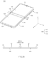
- FIG. 2A is a view illustrating an unfolded state of an electronic device according to an embodiment of the disclosure.
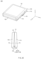
- FIG. 2B is a view illustrating a folded state of an electronic device according to an embodiment of the disclosure.
- FIG 2C is a view of the fully folded state of the electronic device according to an embodiment of the disclosure.
- an axial direction that is parallel to the rotation axes of the first housing 110 and the second housing 120 may be defined.
- the axial direction may be defined as an extension direction of the folding area 143 of the display 140.
- the axial direction may be defined as a long-side direction of the folding area 143.
- the axial direction may mean a direction that is parallel to the y axis of FIG. 1 .
- a first periphery P1 of the electronic device 100 and a second periphery P2 of the electronic device 100, which are parallel to the axial direction may be defined.
- a third periphery P3 of the electronic device 100 and a fourth periphery P4 of the electronic device 100, which are perpendicular to the axial direction may be defined.
- the first periphery P1 and the third periphery P3 may include a portion of the first frame 112 of the first housing 110.
- the second periphery P2 and the fourth periphery P4 may include a portion of the second frame 122 of the second housing 120.
- the unfolded state of the electronic device will be described with reference to FIG. 2A .
- the folded state may include a state, in which the folding area 143 of the display 140 is curved.
- the folded state may include a state, in which the first normal vector n1 of the first area 141 and the second normal vector n2 of the second area 142 define a specific angle.
- the folded state may include a state, in which the third periphery P3 and the fourth periphery P4 define a specific angle other than 180 degrees.
- the fully folded state may mean a state, in which the first periphery P1 and the second periphery P2 substantially contact each other in the folded state.
- the folding area 143 in the fully folded state may have a curved surface having a curvature that is larger than that of the folding area 143 in the folded state.
- the hinge housing 130 in the folded state and the fully folded state, at least a portion of the hinge housing 130 may define a surface of the electronic device 100.
- the hinge housing 130 may be visually exposed between the first housing 110 and the second housing 120.
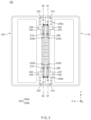
- FIG. 3 is a view illustrating a first housing, a second housing, and a hinge structure of an electronic device according to an embodiment of the disclosure.
- the electronic device 100 may include the hinge structure 200 that is connected to the first housing 110 and the second housing 120.
- the hinge structure 200 may connect the first housing 110 and the second housing 120 such that the first housing 110 and the second housing 120 are rotated about a first rotation axis R1 and a second rotation axis R2.
- the hinge structure 200 may include a first hinge structure 200a, and a second hinge structure 200b that is spaced apart from the first hinge structure 200a in an axial direction (e.g., the y axis direction).
- the first rotation structure 210 of the hinge structure 200 may be connected to the first housing 110.
- the first rotation structure 210 may be rotated about the first rotation axis R1.
- the second rotation structure 220 of the hinge structure 200 may be connected to the second housing 120.
- the second rotation structure 220 may be rotated about the second rotation axis R2.
- the hinge structure 200 may further include a first arm shaft 240S, a first arm part 240, a second arm shaft 250S, a second arm part 250, a first torque structure 201, a second torque structure 202, link structures 260 and 270, and the center bar 280.
- the first arm part 240 may be coupled to the first arm shaft 240S to be rotated about the first arm shaft 240S.
- the first arm part 240 may interwork with rotation of the first rotation structure 210. For example, as the first rotation structure 210 is rotated about the first rotation axis R1 in the unfolding operation or the folding operation, the first arm part 240 may be rotated about the first arm shaft 240S together with the first arm shaft 240S.
- the second arm part 250 may be coupled to the second arm shaft 250S to be rotated about the second arm shaft 250S.
- the second arm part 250 may interwork with rotation of the second rotation structure 220.
- a first link structure 260 may cause rotations of the first housing 110 and the second housing 120 to interwork with each other.
- the first link structure 260 may cause rotations of the first arm shaft 240S and the second arm shaft 250S to interlock with each other when the first housing 110 and the second housing 120 are rotated in opposite directions.
- the first link structure 260 may be configured to be moved in the axial direction in correspondence to rotations of the first arm shaft 240S and the second arm shaft 250S.
- the center bar 280 is moved in the z/-z axis direction.
- the center bar 280 supports a rear surface of the folding area 143 such that the folding area (e.g., the folding area 143 of FIG. 2A ) of the display (e.g., the display 140 of FIG. 2A ) is maintained on a plane in the unfolded state.
- the center bar 280 is moved in the -z axis direction in the folding operation to define a space, in which a portion of the folding area 143 of the display 140 is accommodated.
- the center bar 280 is moved in correspondence to movement of the link structures 260 and 270.
- the hinge structure 200 may include the first torque structure 201 that provides a frictional torque to the first arm shaft 240S.
- the first torque structure 201 may include cam structures and an elastic member, and the elastic member may be compressed by the cam structures to form a frictional torque that is applied in an opposite direction to a rotational direction of the first arm shaft 240S.
- the first torque structure 201 may prevent a folding operation or an unfolding operation of the electronic device, which is not intended, by providing a suitable frictional torque to the first arm shaft 240S.
- the hinge structure 200 may include the second torque structure 202 that provides a frictional torque to the second arm shaft 250S.
- the second torque structure 202 may include cam structures and an elastic member, and the elastic member may be compressed by the cam structures to form a frictional torque that is applied in an opposite direction to a rotational direction of the second arm shaft 250S.
- the second torque structure 202 may prevent a folding operation or an unfolding operation of the electronic device, which is not intended, by providing a suitable frictional torque to the second arm shaft 250S.
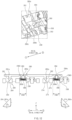
- FIG. 4 is a perspective view of the hinge structure according to an embodiment of the disclosure.
- FIG. 5 is a rear view of the hinge structure according to an embodiment of the disclosure.
- FIG. 6 is an exploded perspective view of the hinge structure according to an embodiment of the disclosure.
- FIG. 7 is an exploded perspective view of the hinge structure according to an embodiment of the disclosure.
- the axial direction may be defined.
- the axial direction may be a direction that is parallel to extension directions of the first rotation axis R1 and the second rotation axis R2.
- a first axial direction 1 may be a direction that faces a fixing structure 230
- a second axial direction 2 may be a direction that faces a second fixing member 238.
- the hinge structure 200 may include the fixing structure 230, the first rotation structure 210, the second rotation structure 220, a first fixing member 236, the second fixing member 238, the first arm shaft 240S, the second arm shaft 250S, the link structures 260 and 270, the first arm part 240, the second arm part 250, the first torque structure 201, and the second torque structure 202.
- the fixing structure 230 may be fixedly disposed in an interior of the hinge housing (e.g., the hinge housing 130 of FIG. 1 ).
- the first rotation structure 210 and the second rotation structure 220 may be coupled to the fixing structure 230 to be rotated.
- the fixing structure 230 may include a first opening area 2391, to which a first guide part 211 of the first rotation structure 210 is coupled.
- the fixing structure 230 may include a first guide rail 233 that guides a rotation path of the first rotation structure 210.
- the first guide rail 233 may be formed on a side wall of the first opening area 2391.
- the first guide rail 233 may be formed on at least one of opposite side walls of the first opening area 2391, which faces the axial direction of the first opening area 2391.
- a first protrusion 213 of the first rotation structure 210 may be accommodated in the first guide rail 233.
- the fixing structure 230 may include a second opening area 2392, to which a second guide part 221 of the second rotation structure 220 is coupled.
- the fixing structure 230 may include a second guide rail 234 that guides a rotation path of the second rotation structure 220.
- the second guide rail 234 may be formed on a side wall of the second opening area 2392.
- the second guide rail 234 may be formed on at least one of opposite side walls of the second opening area 2392, which faces the axial direction of the second opening area 2392.
- a second protrusion 223 of the second rotation structure 220 may be accommodated in the second guide rail 234.
- first fixing member 236 and the second fixing member 238 may be fixedly disposed in the hinge housing 130.
- the center bar 280 may be coupled to the first fixing member 236 and the second fixing member 238.
- a first fixing hole 2362 and a first hole 2361 may be formed in the first fixing member 236.
- the first fixing member 236 may be fixedly coupled to the hinge housing (e.g., the hinge housing 130 of FIG. 1 ) through the first fixing hole 2362 and a coupling member inserted into the first fixing hole 2362.
- the coupling member may include a screw.
- the screw may extend to the hinge housing 130 through the first fixing hole 2362.
- the first fixing member 236 may be coupled to the center bar 280 through the first hole 2361.
- a first protruding part 283 of the center bar 280 may be at least partially inserted into the first hole 2361. Referring to FIGS. 5 and 7 , the first protruding part 283 of the center bar 280 and a first screw 283a coupled to the first protruding part 283 may be inserted into the first hole 2361 of the first fixing member 236.
- a second fixing hole 2382 and a second hole 2381 may be formed in the second fixing member 238.
- the second fixing member 238 may be fixedly coupled to the hinge housing 130 through the second fixing hole 2382 and a coupling member inserted into the second fixing hole 2382.
- the coupling member may include a screw.
- the screw may extend to the hinge housing 130 through the second fixing hole 2382.
- the second fixing member 238 may be coupled to the center bar 280 through the second hole 2381.
- a second protruding part 284 of the center bar 280 may be at least partially inserted into the second hole 2381. Referring to FIGS. 5 and 7 , the second protruding part 284 of the center bar 280 and a second screw 284a coupled to the second protruding part 284 may be inserted into the second hole 2381 of the second fixing member 238.
- first arm shaft 240S and the second arm shaft 250S may pass through the first fixing member 236, and the first fixing member 236 may support rotations of the first arm shaft 240S and the second arm shaft 250S.
- first arm shaft 240S and the second arm shaft 250S may pass through the second fixing member 238, and the second fixing member 238 may support rotations of the first arm shaft 240S and the second arm shaft 250S.
- the first rotation structure 210 may be configured to be rotated in a specific path with respect to the fixing structure 230 fixedly disposed in the hinge housing (e.g., the hinge housing 130 of FIG. 1 ) when the first housing (e.g., the first housing 110 of FIG. 1 ) is folded or unfolded.
- the first rotation structure 210 may include the first guide part 211 coupled to the fixing structure 230 to be rotated, and a first connection part 212 coupled to the first housing 110.
- the first connection part 212 may be folded or unfolded together with the first housing 110 when the electronic device 100 is folded or unfolded.
- the first rotation structure 210 may include the first protrusion 213 that is formed in the first guide part 211.
- the first protrusion 213 may guide the rotation path of the first rotation structure 210 together with the first guide rail 233.
- the first arm part 240 may include a first coupling part 241, a second coupling part 242, and a first extending part 243.
- the first arm part 240 may be coupled to the first rotation structure 210 through a first sliding pin 246 to be slid.
- the first arm part 240 may be coupled to the first arm shaft 240S to be rotated together with the first arm shaft 240S through the first coupling part 241 and the second coupling part 242.
- the first coupling part 241 and the second coupling part 242 may be press-fitted with the first arm shaft 240S.
- the first sliding pin 246 of the first extending part 243 may be coupled to the first rotation structure 210.
- at least a portion of the first sliding pin 246 may be accommodated in a first sliding groove 215 of the first rotation structure 210.
- the first sliding pin 246 may be moved along the first sliding groove 215 when the first rotation structure 210 is rotated.
- the first rotation structure 210 is rotated about the first rotation axis R1
- the first arm part 240 may be rotated about the first arm shaft 240S
- the first arm part 240 may be slid with respect to the first rotation structure 210 at the same time.
- the first arm part 240 may be slid while the first sliding pin 246 is coupled to the first rotation structure 210.
- the first arm shaft 240S is coupled to the fixing structure 230 to be rotated.
- the first arm shaft 240S extends long from the fixing structure 230 in the second axial direction 2.
- the first arm shaft 240S may extend to pass through the first fixing member 236 and the second fixing member 238.
- rotation of the first arm shaft 240S may be supported by the first fixing member 236 and the second fixing member 238.
- an end of the first arm shaft 240S in the first axial direction 1 may be inserted into a recess or an opening formed in the fixing structure 230 to be rotated.
- a first fixing ring 2491 may be coupled to an end of the first arm shaft 240S in the second axial direction 2.
- the first fixing ring 2491 may be configured to restrict movement of the first arm shaft 240S in the axial direction.
- the first fixing ring 2491 may be at least partially inserted into a groove formed on an outer peripheral surface of the first arm shaft 240S.
- the first fixing ring 2491 may include a C-clip that surrounds at least a portion of the first arm shaft 240S.
- the first arm shaft 240S may pass through the first coupling part 241 and the second coupling part 242 of the first arm part 240.
- the first arm shaft 240S may be coupled to the first coupling part 241 and the second coupling part 242 to be rotated together with the first coupling part 241 and the second coupling part 242.
- the first coupling part 241 and the second coupling part 242 may be press-fitted by the first arm shaft 240S.
- the first arm part 240 may be rotated by the first sliding pin 246.
- the first arm shaft 240S may be rotated by the first coupling part 241 and the second coupling part 242.
- the second rotation structure 220 may be configured to be rotated in a specific path with respect to the fixing structure 230 fixedly disposed in the hinge housing (e.g., the hinge housing 130 of FIG. 1 ) when the first housing (e.g., the first housing 110 of FIG. 1 ) is folded or unfolded.
- the second rotation structure 220 may include the second guide part 221 coupled to the fixing structure 230 to be rotated, and a second connection part 222 connected to the second housing 120.
- the second connection part 222 may be folded or unfolded together with the second housing 120 when the electronic device 100 is folded or unfolded.
- the second rotation structure 220 may include the second protrusion 223 that is formed in the second guide part 221.
- the second protrusion 223 may guide the rotation path of the second rotation structure 220 together with the second guide rail 234.
- the second arm part 250 may include a third coupling part 251, a fourth coupling part 252, and a second extending part 253.
- the second arm part 250 may be coupled to the second rotation structure 220 through a second sliding pin 256 to be slid.
- the second arm part 250 may be coupled to the second arm shaft 250S to be rotated together with the second arm shaft 250S through the third coupling part 251 and the fourth coupling part 252.
- the third coupling part 251 and the fourth coupling part 252 may be press-fitted with the second arm shaft 250S.
- the second sliding pin 256 of the second extending part 253 may be coupled to the second rotation structure 220.
- at least a portion of the second sliding pin 256 may be accommodated in a second sliding groove 225 of the second rotation structure 220.
- the second sliding pin 256 may be moved along the second sliding groove 225 when the second rotation structure 220 is rotated.
- the second rotation structure 220 is rotated about the second rotation axis R2
- the second arm part 250 may be rotated about the second arm shaft 250S, and the second arm part 250 may be slid with respect to the second rotation structure 220 at the same time.
- the second arm part 250 may be slid while the second sliding pin 256 is coupled to the second rotation structure 220.
- the second arm shaft 250S is coupled to the fixing structure 230 to be rotated.
- the second arm shaft 250S extends long from the fixing structure 230 in the second axial direction 2.
- the second arm shaft may extend to pass through the first fixing member 236 and the second fixing member 238.
- rotation of the second arm shaft 250S may be supported by the first fixing member 236 and the second fixing member 238.
- an end of the second arm shaft 250S in the first axial direction 1 may be inserted into a recess or an opening formed in the fixing structure 230 to be rotated.
- a second fixing ring 2591 may be coupled to an end of the second arm shaft 250S in the second axial direction 2.
- the second fixing ring 2591 may be configured to restrict movement of the second arm shaft 250S in the axial direction.
- the second fixing ring 2591 may be at least partially inserted into a groove formed on an outer peripheral surface of the second arm shaft 250S.
- the second fixing ring 2591 may include a C-clip that surrounds at least a portion of the second arm shaft 250S.
- the second arm shaft 250S may pass through the third coupling part 251 and the fourth coupling part 252 of the second arm part 250.
- the second arm shaft 250S may be coupled to the third coupling part 251 and the fourth coupling part 252 to be rotated together with the third coupling part 251 and the fourth coupling part 252.
- the third coupling part 251 and the fourth coupling part 252 may be press-fitted with the second arm shaft 250S.
- the second arm part 250 may be rotated by the second sliding pin 256.
- the second arm shaft 250S may be rotated by the third coupling part 251 and the fourth coupling part 252.
- first rotation structure 210 and the second rotation structure 220 may interlock with each other to be rotated at the same angle in opposite directions, through the first arm shaft 240S, the second arm shaft 250S, and the link structures 260 and 270.
- the hinge structure 200 may include the first torque structure 201 that provides a torque to the first arm shaft 240S, and the second torque structure 202 that provides a torque to the second arm shaft 250S.
- the first torque structure 201 and the second torque structure 202 may provide frictional forces corresponding to a restoring torque of the display 140.
- a restoring force by which the display 140 is intended to return to the flat state again, may be applied to the display 140.
- the restoring force may apply a restoring torque to the first arm shaft 240S and the second arm shaft 250S, in the unfolding direction.
- the restoring torque may be applied to the first arm shaft 240S in the counterclockwise direction that is the unfolding direction, and may be applied to the second arm shaft 250S in the clockwise direction that is the unfolding direction.
- the hinge structure 200 may be configured to provide a specific frictional torque that offsets the restoring torque such that the display 140 is maintained in a specific folded state.
- the frictional torque may be proportional to a surface frictional force between the cam structures, and the surface frictional force may be increased by the compressed elastic members 295a, 295b, 295c, and 295d.
- the first torque structure 201 may include first cam structures 244, 245, 291, and 293 that compresses or prolong a third elastic member 295a and a fourth elastic member 295b. When the third elastic member 295a and the fourth elastic member 295b are compressed, surface frictional forces between the first cam structures 244, 245, 291, and 293 may increase and the frictional torque may increase.
- the second torque structure 202 may include second cam structures 254, 255, 292, and 294 that compresses or prolong a fifth elastic member 295c and the sixth elastic member 295d.
- second cam structures 254, 255, 292, and 294 that compresses or prolong a fifth elastic member 295c and the sixth elastic member 295d.
- the hinge structure 200 may include a first cam member 290a and a second cam member 290b.
- the first arm shaft 240S and the second arm shaft 250S may pass through the first cam member 290a.
- the first cam member 290a may be configured to be linearly moved along the first arm shaft 240S and the second arm shaft 250S.
- the first cam member 290a may include a first cam 291 engaged with a first arm cam 244 of the first arm part 240, and a second cam 292 engaged with a third arm cam 254 of the second arm part 250.
- the first arm shaft 240S and the second arm shaft 250S may pass through the second cam member 290b.
- the second cam member 290b may be configured to be linearly moved along the first arm shaft 240S and the second arm shaft 250S.
- the second cam member 290b may include a third cam 293 engaged with a second arm cam 245 of the first arm part 240, and a fourth cam 294 engaged with a fourth arm cam 255 of the second arm part 250.
- the first torque structure 201 may include the first arm cam 244 formed in the first arm part 240, the first cam 291 of the first cam member 290a, the third elastic member 295a, the fourth elastic member 295b, the third cam 293 of the second cam member 290b, and the second arm cam 245 of the first arm part 240. Then, the first arm cam 244 and the second arm cam 245 may be configured to be rotated together with the first arm shaft 240S, and the first cam member 290a and the second cam member 290b may be configured to be linearly in the axial direction.
- first arm cam 244 and the second arm cam 245 may be referenced as rotary cams, and the first cam 291 and the third cam 293 may be referenced as linear cams.
- the third elastic member 295a and the fourth elastic member 295b may be compressed or prolonged through movements of the first cam member 290a and the second cam member 290b.
- the third elastic member 295a may be disposed in the first arm shaft 240S.
- the third elastic member 295a may be disposed between the first cam 291 of the first cam member 290a and the first fixing member 236.
- the third elastic member 295a may be compressed when the first cam member 290a is moved in the second axial direction 2, and may be prolonged when the first cam member 290a is moved in the first axial direction 1.
- the fourth elastic member 295b may be disposed in the first arm shaft.
- the fourth elastic member 295b may be disposed between the third cam 293 of the second cam member 290b and the first fixing member 236.
- the fourth elastic member 295b may be compressed when the second cam member 290b is moved in the first axial direction 1, and may be prolonged when the second cam member 290b is moved in the second axial direction 2.
- the second torque structure 202 may include the third arm cam 254 formed in the second arm part 250, the second cam 292 of the first cam member 290a, the fifth elastic member 295c, the sixth elastic member 295d, the fourth cam 294 of the second cam member 290b, and the fourth arm cam 255 of the second arm part 250. Then, the third arm cam 254 and the fourth arm cam 255 may be configured to be rotated together with the second arm shaft 250S, and the first cam member 290a and the second cam member 290b may be configured to be linearly moved in the axial direction.
- the third arm cam 254 and the fourth arm cam 255 may be referenced as rotary cams, and the second cam 292 and the fourth cam 294 may be referenced as linear cams.
- the fifth elastic member 295c and the sixth elastic member 295d may be compressed or prolonged through movements of the first cam member 290a and the second cam member 290b.
- the fifth elastic member 295c may be disposed in the second arm shaft 250S.
- the fifth elastic member 295c may be disposed between the second cam 292 of the first cam member 290a and the first fixing member 236.
- the fifth elastic member 295c may be compressed when the first cam member 290a is moved in the second axial direction 2, and may be prolonged when the first cam member 290a is moved in the first axial direction 1.
- the sixth elastic member 295d may be disposed in the second arm shaft 250S.
- the sixth elastic member 295d may be disposed between the fourth cam 294 of the second cam member 290b and the first fixing member 236.
- the sixth elastic member 295d may be compressed when the second cam member 290b is moved in the first axial direction 1, and may be prolonged when the second cam member 290b is moved in the second axial direction 2.
- the link structures 260 and 270 may be coupled to the first arm shaft 240S and the second arm shaft 250S, and may be configured to be linearly moved in the axial direction in correspondence to rotations of the first arm shaft 240S and the second arm shaft 250S, respectively.
- the link structures 260 and 270 may cause the first arm shaft 240S and the second arm shaft 250S to interlock with each other such that the first rotation structure 210 and the second rotation structure 220 are rotated at the same angle in opposite directions.
- the link structures 260 and 270 may include a first link structure 260 and a second link structure 270.
- the first link structure 260 and the second link structure 270 may be spaced apart from each other in the axial direction.
- the first arm part 240, the second arm part 250, the first cam structures 244, 245, 291, and 293, the second cam structures 254, 255, 292, and 294, and the first fixing member 236 may be disposed between the first link structure 260 and the second link structure 270.
- the first link structure 260 may include a first part 260a, through which the first arm shaft 240S passes, a second part 260b, through which the second arm shaft 250S passes, and a first central part 260c connecting the first part 260a and the second part 260b.
- the first part 260a and the second part 260b may extend from the first central part 260c in a direction that is substantially perpendicular to the axial direction.
- a first guide groove 261 may be formed in the first part 260a.
- a first guide pin 248 of the first arm shaft 240S may be accommodated in the first guide groove 261.
- the first guide pin 248 may be moved along the first guide groove 261, and thus, the first link structure 260 may be moved to one side in the axial direction.
- the first guide groove 261 may have a spiral shape that surrounds the first arm shaft 240S.
- the first guide groove 261 may extend in a circumferential direction and an axial direction of the first arm shaft 240S.
- An axial extension length of the first guide groove 261 may correspond to an axial movement distance of the first link structure 260.
- a circumferential extension length of the first guide groove 261 may correspond to a rotational angle of the first link structure 260.
- a second guide groove 262 may be formed in the second part 260b.
- a third guide pin 258 of the second arm shaft 250S may be accommodated in the second guide groove 262.
- the third guide pin 258 may be moved along the second guide groove 262, and thus, the second link structure 270 may be moved to one side in the axial direction.
- the second guide groove 262 may have a spiral shape that surrounds the second arm shaft 250S.
- the second guide groove 262 may extend in a circumferential direction and an axial direction of the second arm shaft 250S.
- An axial extension length of the second guide groove 262 may correspond to an axial movement distance of the second link structure 270.
- a circumferential extension length of the second guide groove 262 may correspond to a rotational angle of the second link structure 270.
- first guide groove 261 and the second guide groove 262 may have shape that are symmetrical to each other with respect to a central axis.
- the central axis may be defined as an axis that is spaced apart from the first arm shaft 240S and the second arm shaft 250S by the same distance and is parallel to the axial direction.
- the first guide groove 261 and the second guide groove 262 may extend in the same axial direction by the same length, and may extend at the same angle in opposite circumferential directions. For example, in the folding operation and the unfolding operation, the first rotation structure 210 and the second rotation structure 220 may be rotated in opposite directions. Accordingly, the first arm shaft 240S and the second arm shaft 250S may be rotated in opposite directions.
- first guide groove 261 and the second guide groove 262 may be symmetrical to each other with respect to the central axis such that the first link structure 260 is moved in the same direction when the first arm shaft 240S and the second arm shaft 250S are rotated in opposite directions.
- the first guide groove 261 may extend in the axial direction by a first distance d1, and may extend at a first angle ⁇ 1 in the circumferential direction of the first arm shaft 240S.
- the second guide groove 262 may extend in the axial direction by the first distance d1, and may extend by the first angle ⁇ 1 in the circumferential direction of the second arm shaft 250S.
- the first angle ⁇ 1 and a second angle ⁇ 2 may be the same.
- the first distance d1 and a second distance d2 may be different.
- the first link structure 260 may cause the first arm shaft 240S and the second arm shaft 250S to interlock each other such that the first arm shaft 240S and the second arm shaft 250S are rotated in opposite directions but are rotated at the same angle.
- the second link structure 270 may include a third part 270a, through which the first arm shaft 240S passes, a fourth part 270b, through which the second arm shaft 250S passes, and a second central part 270c connecting the third part 270a and the fourth part 270b.
- the third part 270a and the fourth part 270b may extend from the second central part 270c in a direction that is substantially perpendicular to the axial direction.
- a third guide groove 271 may be formed in the third part 270a.
- a second guide pin 249 of the first arm shaft 240S may be accommodated in the third guide groove 271.
- the second guide pin 249 may be moved along the third guide groove 271, and thus, the second link structure 270 may be moved to one side in the axial direction.
- the third guide groove 271 may have a spiral shape that surrounds the first arm shaft 240S.
- the third guide groove 271 may extend in a circumferential direction and an axial direction of the first arm shaft 240S.
- An axial extension length of the first guide groove 261 may correspond to an axial movement distance of the second link structure 270.
- a circumferential extension length of the third guide groove 271 may correspond to a rotational angle of the second link structure 270.
- a fourth guide groove 272 may be formed in the fourth part 270b.
- a fourth guide pin 259 of the second arm shaft 250S may be accommodated in the fourth guide groove 272.
- the fourth guide pin 259 may be moved along the fourth guide groove 272, and thus, the second link structure 270 may be moved to one side in the axial direction.
- the fourth guide groove 272 may have a spiral shape that surrounds the second arm shaft 250S.
- the second guide groove 262 may extend in a circumferential direction and an axial direction of the second arm shaft 250S.
- An axial extension length of the second guide groove 262 may correspond to an axial movement distance of the second link structure 270.
- a circumferential extension length of the fourth guide groove 272 may correspond to a rotational angle of the second link structure 270.
- the third guide groove 271 and the fourth guide groove 272 may have a shape that are symmetrical to each other with respect to a central axis.
- the central axis may be defined as an axis that is spaced apart from the first arm shaft 240S and the second arm shaft 250S by the same distance and is parallel to the axial direction.
- the third guide groove 271 and the fourth guide groove 272 may extend in the same axial direction by the same length, and may extend at the same angle in opposite circumferential directions. For example, in the folding operation and the unfolding operation, the first rotation structure 210 and the second rotation structure 220 may be rotated in opposite directions. Accordingly, the first arm shaft 240S and the second arm shaft 250S may be rotated in opposite directions.
- the third guide groove 271 and the fourth guide groove 272 may be symmetrical to each other with respect to the central axis such that the second link structure 270 is moved in the same direction when the first arm shaft 240S and the second arm shaft 250S are rotated in opposite directions.
- the third guide groove 271 may extend in the axial direction by a second distance d2, and may extend at a second angle ⁇ 2 in the circumferential direction of the first arm shaft 240S.
- the fourth guide groove 272 may extend in the axial direction by the second distance d2, and may extend by the second angle ⁇ 2 in the circumferential direction of the second arm shaft 250S.
- the first angle ⁇ 1 and the second angle ⁇ 2 may be the same.
- the first distance d1 and the second distance d2 may be different.
- the second link structure 270 may cause the first arm shaft 240S and the second arm shaft 250S to interlock each other such that the first arm shaft 240S and the second arm shaft 250S are rotated in opposite directions but are rotated at the same angle.
- the center bar 280 is configured to support a rear surface of the display 140 such that the folding area (e.g., the folding area 143 of FIG. 2A ) of the display (e.g., the display 140 of FIG. 2A ) is maintained on a plane in the unfolded state.
- the center bar 280 is configured to support the folding area 143 of the display 140, which is at least partially curved in the folded state.
- the center bar 280 is configured to be moved in the z/-z axis direction in the folding operation and the unfolding operation.
- the center bar 280 may interlock with movements of the first link structure 260 and the second link structure 270.
- the center bar 280 may be coupled to the first fixing member 236, the second fixing member 238, the first link structure 260, and the second link structure 270. Referring to FIG. 4 , the center bar 280 may at least partially overlap the first central part 260c of the first link structure 260, the second central part 270c of the second link structure 270, the first fixing member 236, and the second fixing member 238, when the hinge structure 200 is viewed from a top. In an embodiment, the center bar 280 may extend long in the axial direction.
- the center bar 280 may include the first protruding part 283, the second protruding part 284, a first inclined protrusion 281, and a second inclined protrusion 282, which are formed on a rear surface of the center bar 280.
- a first elastic member 288 may be disposed in the first protruding part 283.
- the first elastic member 288 may surround at least a portion of the first protruding part 283.
- the first screw 283a may be coupled to the first protruding part 283.
- the first protruding part 283 may be at least partially inserted into the first hole 2361 of the first fixing member 236. Then, at least a portion of the first screw 283a may be located in an interior of the first hole 2361.
- a head of the first screw 283a may support one side of the first elastic member 288.
- the head of the first screw 283a may be referenced as a flange.
- a second elastic member 289 may be disposed in the second protruding part 284.
- the second elastic member 289 may surround at least a portion of the second protruding part 284.
- the second screw 284a may be coupled to the second protruding part 284.
- the second protruding part 284 may be at least partially inserted into the second hole 2381 of the second fixing member 238. Then, at least a portion of the second screw 284a may be located in an interior of the second hole 2381.
- a head of the second screw 284a may support one side of the second elastic member 289.
- the head of the second screw 284a may be referenced as a flange.
- the first protruding part 283 and the second protruding part 284 may extend long as compared with a z axis displacement, by which the center bar 280 may be moved. Accordingly, the center bar 280 may be moved in the z axis direction while the first protruding part 283 and the second protruding part 284 are accommodated in the first hole 2361 and the second hole 2381, respectively. That is, the first protruding part 283 and the second protruding part 284 may guide movement of the center bar 280.
- the first elastic member 288 may be at least partially located in an interior of the first hole 2361 of the first fixing member 236.
- the first elastic member 288 may provide an elastic force to the center bar 280.
- the first elastic member 288, for example, may be configured to be compressed as the center bar 280 is moved in the z axis direction and be prolonged as the center bar 280 is moved in the -z axis direction.
- the second elastic member 289 may be at least partially located in an interior of the second hole 2381 of the second fixing member 238.
- the second elastic member 289 may provide an elastic force to the center bar 280.
- the second elastic member 289 for example, may be configured to be compressed as the center bar 280 is moved in the z axis direction and be prolonged as the center bar 280 is moved in the -z axis direction.
- the first inclined protrusion 281 may include a third inclined surface 281a.
- the third inclined surface 281a may at least partially contact a first inclined surface 264 formed in the first central part 260c of the first link structure 260.
- the third inclined surface 281a may be pressed in the z axis direction by the first inclined surface 264.
- the second inclined protrusion 282 may include a fourth inclined surface 282a.
- the fourth inclined surface 282a may at least partially contact a second inclined surface 274 formed in the second central part 270c of the second link structure 270.
- the fourth inclined surface 282a may be pressed in the z axis direction by the second inclined surface 274.
- the center bar 280 may be configured to be moved in the z axis direction and the -z axis direction through movements of the first link structure 260 and the second link structure 270, and may be additionally moved by elastic forces of the first elastic member 288 and the second elastic member 289.
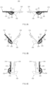
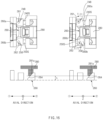
- FIGS. 8A, 8B, and 8C are views illustrating a rotation operation of the hinge structure according to various embodiments of the disclosure.
- FIGS. 8A to 8C are views of the hinge structure, when viewed in direction "A" illustrated in FIG. 3 .
- FIG. 8A is a view illustrating a hinge structure in the unfolded state.
- FIG. 8B is a view illustrating a hinge structure in the folded state.
- FIG. 8C is a view illustrating a hinge structure in the fully folded state.
- the first guide rail 233 and the second guide rail 234 may be formed in the fixing structure 230.
- the first guide rail 233 may have a substantially arc-shape.
- a center of the arc of the first guide rail 233 may be the first rotation axis R1. That is, the first guide rail 233 may guide the first rotation structure 210 such that the first rotation structure 210 is rotated along a rotation path, a center of which is the first rotation axis R1.
- the second guide rail 234 may have a substantially arc-shape.
- a center of the arc of the second guide rail 234 may be the second rotation axis R2. That is, the second guide rail 234 may guide the second rotation structure 220 such that the second rotation structure 220 is rotated along a rotation path, a center of which is the second rotation axis R2.
- the first rotation structure 210 may include the first connection part 212 and the first guide part 211.
- the first guide part 211 may have a substantially cylindrical shape.
- a cross-section of the first guide part 211 may have a substantially arc shape.
- the first rotation structure 210 may be rotated about the first rotation axis R1 while the first protrusion 213 of the first guide part 211 is accommodated in the first guide rail 233 of the fixing structure 230.
- the first rotation structure 210 may be rotated along a rotation path having an arc shape, a center of which is the first rotation axis R1.
- the second rotation structure 220 may include the second connection part 222 and the second guide part 221.
- the second guide part 221 may have a substantially cylindrical shape.
- a cross-section of the second guide part 221 may have a substantially arc shape.
- the second rotation structure 220 may be rotated about the second rotation axis R2 while the second protrusion 223 is accommodated in the second guide rail 234.
- the second rotation structure 220 may be rotated along a rotation path having an arc shape, a center of which is the second rotation axis R2.
- first rotation axis R1 and the second rotation axis R2 may be parallel to the axial direction of the hinge structure 200. In an embodiment, the first rotation axis R1 and the second rotation axis R2 may be formed at locations that are spaced apart from the first connection part 212 of the first rotation structure 210 and the second connection part 222 of the second rotation structure 220 in the z axis direction.
- the first connection part 212 may restrict a direction, in which the first rotation structure 210 may be rotated, to one in the unfolded state.
- a first end of the first guide rail 233 may be opened and another second end thereof may be covered by the first connection part 212.
- the first rotation structure 210 may be rotated about the first rotation axis R1 in the clockwise direction with reference to the drawings in the unfolded state and cannot be rotated in the counterclockwise direction.
- the second connection part 222 may restrict a direction, in which the second rotation structure 220 may be rotated, to one in the unfolded state.
- a third end of the second guide rail 234 may be opened and another fourth end thereof may be covered by the second connection part 222.
- the second rotation structure 220 may be rotated about the second rotation axis R2 in the counterclockwise direction with reference to the drawings in the unfolded state and cannot be rotated in the clockwise direction.
- FIGS. 9A, 9B, and 9C are views illustrating rotation operations and sliding operations of the arm part and the rotation structure of the hinge structure according to various embodiments of the disclosure.
- FIGS. 9A to 9C views illustrating the hinge structure, when viewed in direction "B" illustrated in FIG. 3 .
- FIG. 9A is a view illustrating a hinge structure in the unfolded state.
- FIG. 9B is a view illustrating a hinge structure in the folded state.
- FIG. 9C is a view illustrating a hinge structure in the fully folded state.
- the rotation structures 210 and 220 and the arm parts 240 and 250 may be rotated about different axes.
- the rotation structures 210 and 220 and the arm parts 240 and 250 may be rotated in different rotation paths. Due to the difference of the rotation paths of the rotation structures 210 and 220 and the arm parts 240 and 250, the arm parts 240 and 250 may be slid when the hinge structure 200 is folded or unfolded.
- the first rotation structure 210 may be rotated about the first rotation axis R1 in the first rotation direction.
- the first rotation structure 210 may be rotated in the clockwise direction.
- a point of the first rotation structure 210, at which the first sliding pin 246 is located may be defined as a first point A1.
- the first point A1 of the first rotation structure 210 may be moved along a first rotation path PA1.
- the first arm part 240 and the first sliding pin 246 may be rotated about the first arm shaft 240S.
- the first arm part 240 and the first sliding pin 246 may be rotated in the clockwise direction.
- the first sliding pin 246 in the unfolded state, may be located at the first point A1, and in the folded state, the first sliding pin 246 may be located at a location that is spaced apart from the first point A1 in a direction that is perpendicular to the axial direction.
- the first sliding pin 246 may be moved along a second rotation path PA2 in the folding and unfolding operations.
- first rotation path PA1 and the second rotation path PA2 may be different.
- first rotation axis R1 and the first arm shaft 240S may be parallel to each other but do not coincide with each other, and the rotation radii of the first rotation structure 210 and the first arm part 240 may not coincide with each other.
- the first arm part 240 and the first sliding pin 246 may be slid with respect to the first rotation structure 210.
- the sliding operations of the first sliding pin 246 and the first arm part 240 may be guided as the first sliding pin 246 is accommodated in the first sliding groove 215 of the first rotation structure 210.
- a distance between the first sliding pin 246 and the first point A1 may increase.
- the distance between the first sliding pin 246 and the first point A1 may decrease.
- the second rotation structure 220 may be rotated about the second rotation axis R2 in the second rotation direction.
- the second rotation structure 220 may be rotated in the counterclockwise direction.
- a point of the second rotation structure 220, at which the second sliding pin 256 is located may be defined as a second point A2.
- the second point A2 may be moved along a third rotation path PA3.
- the second arm part 250 and the second sliding pin 256 may be rotated about the second arm shaft 250S.
- the second arm part 250 and the second sliding pin 256 may be rotated in the counterclockwise direction.
- the second sliding pin 256 may be located at the second point A2
- the second sliding pin 256 may be located at a location that is spaced apart from the second point A2 in a direction that is perpendicular to the axial direction.
- the second sliding pin 256 may be moved along a fourth rotation path PA4 in the folding and unfolding operations.
- the third rotation path PA3 and the fourth rotation path PA4 may be different.
- the second rotation axis R2 and the second arm shaft 250S may be parallel to each other but do not coincide with each other, and the rotation radii of the second rotation structure 220 and the second arm part 250 may not coincide with each other.
- the second arm part 250 and the second sliding pin 256 may be slid with respect to the second rotation structure 220.
- the sliding operations of the second sliding pin 256 and the second arm part 250 may be guided as the second sliding pin 256 is accommodated in the second sliding groove 225 of the second rotation structure 220.
- a distance between the second sliding pin 256 and the second point A2 may increase.
- the distance between the second sliding pin 256 and the second point A2 may decrease.
- FIG. 10 is a view illustrating the link structure and the center bar of the hinge structure in the unfolded state according to an embodiment of the disclosure.
- FIG. 11 is a view illustrating the link structure and the center bar of the hinge structure in the fully folded state according to an embodiment of the disclosure.
- the link structures 260 and 270 may be configured to be moved in the axial direction.
- the first link structure 260 and the second link structure 270 may be disposed at locations that are spaced apart from each other in the axial direction.
- the first link structure 260 may be located at a location that is spaced apart from the second link structure 270 in the first axial direction 1.
- the second link structure 270 may be located at a location that is spaced apart from the first link structure 260 in the second axial direction 2.
- first coupling part 241 and the second coupling part 242 of the first arm part 240, the third coupling part 251 and the fourth coupling part 252 of the second arm part 250, the first fixing member 236, the first cam member 290a, the second cam member 290b, and the elastic members 295a, 295b, 295c, and 295d may be disposed between the first link structure 260 and the second link structure 270.
- the first link structure 260 may be configured such that the first part 260a is coupled to the first arm shaft 240S and the second part 260b is coupled to the second arm shaft 250S.
- the first link structure 260 may be moved in the axial direction along the first arm shaft 240S and the second arm shaft.
- the first guide pin 248 of the first arm shaft 240S may be located in the first guide groove 261 formed in the first part 260a.
- the third guide pin 258 of the second arm shaft 250S may be located in the second guide groove 262 formed in the second part 260b.
- the first link structure 260 may be disposed between the fixing structure 230 and the arm parts 240 and 250.
- the first part 260a of the first link structure 260 may be disposed between the fixing structure 230 and the first coupling part 241 of the first arm part 240
- the second part 260b may be disposed between the fixing structure 230 and the third coupling part 251 of the second arm part 250.
- the first link structure 260 may be disposed to be spaced apart from the fixing structure 230 and/or the arm parts 240 and 250 in the axial direction.
- the first link structure 260 may at least partially contact the fixing structure 230, and may be spaced apart from the first coupling part 241 of the first arm part 240 and the third coupling part 251 of the second arm part 250 by a first distance d1.
- the first distance d1 may be substantially the same as or larger than the axial movement displacement of the first link structure 260.
- FIG. 10 corresponding to the unfolded state
- the first link structure 260 may at least partially contact the first coupling part 241 of the first arm part 240 and the third coupling part 251 of the second arm part 250, and may be spaced apart from the fixing structure 230 by the first distance d1.
- the first distance d1 may be substantially the same as or larger than the axial movement displacement of the first link structure 260.
- the fixing structure 230 and the arm parts 240 and 250 may perform a stopper function of restricting a maximum movement distance of the first link structure 260.
- the first guide pin 248 may be located at a first end 261a of the first guide groove 261, and the third guide pin 258 may be located at a first end 262a of the second guide groove 262.
- the unfolded state may include a state, in which the first part 260a and the second part 260b of the first link structure 260 at least partially contact the fixing structure 230.
- the first guide pin 248 may be located at a second end 261b of the first guide groove 261, and the third guide pin 258 may be located at a second end 262b of the second guide groove 262.
- the fully folded state may include a state, in which the first part 260a of the first link structure 260 at least partially contacts the first coupling part 241 of the first arm part 240 and the second part 260b of the first link structure 260 at least partially contacts the third coupling part 251 of the second arm part 250.
- distances between the first ends 261a and 262a and the second ends 261b and 262b of the first guide groove 261 and the second guide groove 262, which are measured in the axial direction, may be substantially the same as the first distance d1.
- the second link structure 270 may be configured such that the third part 270a is coupled to the first arm shaft 240S and the fourth part 270b is coupled to the second arm shaft 250S.
- the second link structure 270 may be moved in the axial direction along the first arm shaft 240S and the second arm shaft 250S.
- the second guide pin 249 of the first arm shaft 240S may be located in the third guide groove 271 formed in the third part 270a.
- the fourth guide pin 259 of the second arm shaft 250S may be located in the fourth guide groove 272 formed in the fourth part 270b.
- the second link structure 270 may be disposed between the second fixing member 238 and the arm parts 240 and 250.
- the third part 270a of the second link structure 270 may be disposed between the second fixing member 238 and the second coupling part 242 of the first arm part 240
- the fourth part 270b may be disposed between the second fixing member 238 and the fourth coupling part 252 of the second arm part 250.
- the second link structure 270 may be disposed to be spaced apart from the second fixing member 238 and/or the arm parts 240 and 250 in the axial direction.
- the second link structure 270 may at least partially contact the second fixing member 238, and may be spaced apart from the second coupling part 242 of the first arm part 240 and the fourth coupling part 252 of the second arm part 250 by a second distance d2.
- the second distance d2 may be substantially the same as or larger than the axial movement displacement of the second link structure 270.
- FIG. 10 corresponding to the unfolded state
- the second link structure 270 may at least partially contact the second coupling part 242 of the first arm part 240 and the fourth coupling part 252 of the second arm part 250, and may be spaced apart from the second fixing member 238 by the second distance d2.
- the second distance d2 may be substantially the same as or larger than the axial movement displacement of the second link structure 270.
- the second fixing member 238 and the arm parts 240 and 250 may perform a stopper function of restricting a maximum movement distance of the second link structure 270.
- the second guide pin 249 may be located at a first end 271a of the third guide groove 271, and the fourth guide pin 259 may be located at a first end 272a of the fourth guide groove 272.
- the unfolded state may include a state, in which the third part 270a and the fourth part 270b of the second link structure 270 at least partially contact the second fixing member 238.
- the second guide pin 249 may be located at a second end 271b of the third guide groove 271, and the fourth guide pin 259 may be located at a second end 272b of the fourth guide groove 272.
- the fully folded state may include a state, in which the third part 270a of the second link structure 270 at least partially contacts the second coupling part 242 of the first arm part 240 and the fourth part 270b of the second link structure 270 at least partially contacts the fourth coupling part 252 of the second arm part 250.
- distances between the first ends 271a and 272a and the second ends 271b and 272b of the third guide groove 271 and the fourth guide groove 272, which are measured in the axial direction, may be substantially the same as the second distance d2.
- the first distance d1 and the second distance d2 may be the same.
- a displacement of the first link structure 260 and a displacement of the second link structure 270 may be the same.
- the displacement (e.g., the first distance d1) of the first link structure 260 and the displacement (e.g., the second distance d2) of the second link structure 270 are not limited to being necessarily the same.
- the second link structure 270 may be configured to have a displacement that is larger than that of the first link structure 260 in the axial direction.
- the third guide groove 271 and the fourth guide groove 272 of the second link structure 270 may extend longer in the axial direction, and the second fixing member 238 and the arm parts 240 and 250 may be disposed to have a larger distance in consideration of the increased displacements.
- the first rotation structure 210, the first arm part 240, and the first arm shaft 240S may be rotated in the clockwise direction when viewed in the second axial direction 2.
- the first guide pin 248 and the second guide pin 249 provided to the first arm shaft 240S may be rotated in the clockwise direction.
- the second rotation structure 220, the second arm part 250, and the second arm shaft 250S may be rotated in the counterclockwise direction when viewed in the second axial direction 2.
- the third guide pin 258 and the fourth guide pin 259 provided to the second arm shaft 250S may be rotated in the counterclockwise direction.
- the first link structure 260 may be configured to be moved in the second axial direction 2
- the second link structure 270 may be configured to be moved in the first axial direction .
- the center bar 280 may be moved in the -z axis direction in the folding operation.
- the center bar 280 may be moved in the -z axis direction while the second protruding part 284 of the center bar 280 is accommodated in the second hole 2381 of the second fixing member 238.
- the first rotation structure 210, the first arm part 240, and the first arm shaft 240S may be rotated in the counterclockwise direction when viewed in the second axial direction 2.
- the first guide pin 248 and the second guide pin 249 provided to the first arm shaft 240S may be rotated in the counterclockwise direction.
- the second rotation structure 220, the second arm part 250, and the second arm shaft 250S may be rotated in the clockwise direction when viewed in the second axial direction 2.
- the third guide pin 258 and the fourth guide pin 259 provided to the second arm shaft 250S may be rotated in the clockwise direction.
- the first link structure 260 may be configured to be moved in the first axial direction 1, and the second link structure 270 may be configured to be moved in the second axial direction 2.
- the center bar 280 may be moved in the z axis direction in the folding operation.
- the center bar 280 may be moved in the z axis direction while the second protruding part 284 of the center bar 280 is accommodated in the second hole 2381 of the second fixing member 238.
- movement directions of the first link structure 260 and the second link structure 270 may be related to extension directions of the guide grooves 261, 262, 271, and 272.
- the second ends 261b and 262b of the first guide groove 261 and the second guide groove 262 of the first link structure 260 may be located in the first axial direction 1 of the first ends 261a and 262a, and thus, the first link structure 260 may be moved in the second axial direction 2 in the folding operation.
- the second ends 271b and 272b of the third guide groove 271 and the fourth guide groove 272 of the second link structure 270 may be located in the second axial direction 2 of the first ends 271a and 272a, and thus, the second link structure 270 may be moved in the first axial direction 1 in the folding operation.
- FIGS. 10 and 11 illustrate that the first link structure 260 and the second link structure 270 are moved in opposite directions, but the hinge structure 200 according to embodiments disclosed in the disclosure is not limited to being necessarily moved in opposite directions.
- the first link structure 260 and the second link structure 270 may be configured to be moved in the same direction.
- the guide grooves 261 and 262 of the first link structure 260 and the guide grooves 271 and 272 of the second link structure 270 may extend in the same direction.
- FIG. 12 is a view illustrating the link structure of the hinge structure in the unfolded state according to an embodiment of the disclosure.
- FIG. 13 is a view illustrating the link structure of the hinge structure in the fully folded state according to an embodiment of the disclosure.
- a first opening 263 may be formed in the first central part 260c of the first link structure 260.
- a portion of a side wall of the first opening 263 may include the first inclined surface 264.
- the first inclined surface 264 may at least partially contact the third inclined surface 281a of the first inclined protrusion 281.
- the first inclined surface 264 may be formed to be inclined in the -z axis direction as it goes in the first axial direction 1.
- a second opening 273 may be formed in the second central part 270c of the second link structure 270.
- a portion of a side wall of the second opening 273 may include the second inclined surface 274.
- the second inclined surface 274 may at least partially contact the fourth inclined surface 282a of the second inclined protrusion 282.
- the second inclined surface 274 may be formed to be inclined in the z axis direction as it goes in the first axial direction 1.
- At least portions of the first protruding part 283 and the first elastic member 288 may be disposed in an interior of the first hole 2361 of the first fixing member 236.
- a first stepped portion 2363 that faces a first flange 283b of the first protruding part 283 or the head of the first screw 283a in the z axis direction may be formed on an inner surface of the first hole 2361.
- the first stepped portion 2363 may support the first elastic member 288.
- At least portions of the second protruding part 284 and the second elastic member 289 may be disposed in an interior of the second hole 2381 of the second fixing member 238.
- a second stepped portion 2383 that faces a second flange 284b of the second protruding part 284 or the head of the second screw 284a in the z axis direction may be formed on an inner surface of the second hole 2381.
- the second stepped portion 2383 may support the second elastic member 289.
- the center bar 280 may be coupled to the first link structure 260, the second link structure 270, the first fixing member 236, and the second fixing member 238 to be moved in the z axis direction.
- the center bar 280 may include the first inclined protrusion 281, the second inclined protrusion 282, the first protruding part 283, and the second protruding part 284, which protrude in the -z axis direction.
- the center bar 280 may be disposed such that the first inclined protrusion 281 is at least partially accommodated in the first opening 263 of the first link structure 260, the second inclined protrusion 282 is at least partially accommodated in the second opening 273 of the second link structure 270, the first protruding part 283 is at least partially accommodated in the first hole 2361 of the first fixing member 236, and the second protruding part 284 is at least partially accommodated in the second hole 2381 of the second fixing member 238.
- the first protruding part 283 may include the first flange 283b formed at the -z axis end thereof.
- the first flange 283b may support one side of the first elastic member 288.
- the first protruding part 283 may include a first protruding boss and the first screw 283a coupled to the first protruding boss.
- the head of the first screw 283a may define the first flange 283b.
- the first protruding part 283 is not limited to being formed through coupling of the first protruding boss and the first screw 283a, and the first protruding part 283 may include various stepped structures or flange structures that may support the first elastic member 288.
- the second protruding part 284 may include the second flange 284b formed at the -z axis end thereof.
- the second flange 284b may support one side of the second elastic member 289.
- the second protruding part 284 may include a second protruding boss and the second screw 284a coupled to the second protruding boss.
- the head of the second screw 284a may define the flange.
- the second protruding part 284 is not limited to being formed through coupling of the second protruding boss and the second screw 284a, and the second protruding part 284 may include various stepped structures or flange structures that may support the second elastic member 289.
- the first elastic member 288 may be disposed to surround at least a portion of the first protruding part 283.
- One side of the first elastic member 288 may be supported by the first flange 283b of the first protruding part 283 or the head of the first screw 283a, and an opposite side thereof may be supported by the first stepped portion 2363 of the first hole 2361 of the first fixing member 236.
- the first stepped portion 2363 may face the first flange 283b of the first protruding part 283 or the head of the first screw 283a in the z axis direction.
- the first elastic member 288 may be in a compressed state in the unfolded state of FIG.
- the first elastic member 288 may be a further compressed state in the unfolded state and the fully folded state as compared with an equilibrium state.
- the first elastic member 288 may be configured to be supported by the first stepped portion 2363 and press the first flange 283b of the first protruding part 283 in the -z axis direction in the unfolded state.
- the center bar 280 may be moved by a specific height "h" in the -z axis direction in the fully folded state, and may provide a space, in which the folded area 143 of the display 140 is located, in the folded state (e.g., FIG. 2B ) or the fully folded state (e.g., FIG. 2C ).
- the second elastic member 289 may be disposed to surround at least a portion of the second protruding part 284.
- One side of the second elastic member 289 may be supported by the second flange 284b of the second protruding part 284 or the head of the second screw 284a, and an opposite side thereof may be supported by the second stepped portion 2383 of the second hole 2381 of the second fixing member 238.
- the second stepped portion 2383 may face the second flange 284b of the second protruding part 284 or the head of the second screw 284a in the z axis direction.
- the second elastic member 289 may be in a compressed state in the unfolded state of FIG.
- the second elastic member 289 may be a further compressed state in the unfolded state and the fully folded state as compared with an equilibrium state.
- the second elastic member 289 may be configured to be supported by the second stepped portion 2383 and press the second flange 284b of the second protruding part 284 in the -z axis direction in the unfolded state.
- the center bar 280 may be moved by the specific height "h" in the -z axis direction in the fully folded state, and may provide a space, in which the folding area (e.g., the folding area 143 of FIG. 2B ) of the display (e.g., the display 140 of FIG. 2B ) is located, in the folded state (e.g., FIG. 2B ) or the fully folded state (e.g., FIG. 2C ).
- the first inclined protrusion 281 may include the third inclined surface 281a that at least partially contacts the first inclined surface 264 of the first link structure 260.
- the third inclined surface 281a may be formed to be inclined in the -z axis direction as it goes in the first axial direction 1.
- the third inclined surface 281a and the first inclined surface 264 may at least partially surface-contact each other.
- an inclination direction of the third inclined surface 281a may be related to a direction of the first inclined surface 264 of the first link structure 260 and a movement direction of the first link structure 260.
- the third inclined surface 281a may be inclined such that the center bar is moved in the -z axis direction in the folding operation.
- the inclination directions of the third inclined surface 281a and the first inclined surface 264 may be variously provided according to the movement direction of the first link structure 260.
- the second inclined protrusion 282 may include the fourth inclined surface 282a that at least partially contacts the second inclined surface 274 of the second link structure 270.
- the fourth inclined surface 282a may be formed to be inclined in the -z axis direction as it goes in the first axial direction 1.
- the fourth inclined surface 282a and the second inclined surface 274 may at least partially surface-contact each other.
- an inclination direction of the fourth inclined surface 282a may be related to a direction of the second inclined surface 274 of the second link structure 270 and a movement direction of the second link structure 270.
- the fourth inclined surface 282a may be inclined such that the center bar 280 is moved in the -z axis direction in the folding operation.
- the inclination directions of the fourth inclined surface 282a and the second inclined surface 274 may be variously provided according to the movement direction of the second link structure 270.
- the hinge structure 200 may be folded from the unfolded state illustrated in FIG. 12 to the folded state illustrated in FIG. 13 .
- the first rotation structure 210, the first arm part 240, and the first arm shaft 240S may be rotated in the clockwise direction.
- the second rotation structure 220, the second arm part 250, and the second arm shaft 250S may be rotated in the counterclockwise direction.
- the first link structure 260 may be moved in the second axial direction 2 by the first guide pin 248 and the third guide pin 258.
- the compressed first elastic member 288 may press the first flange 283b of the first protruding part 283 in the -z axis direction.
- the first inclined surface 264 may be moved in the second axial direction 2 along the third inclined surface 281a, and the third inclined surface 281a may be moved in the -z axis direction along the first inclined surface 264.
- the center bar 280 may be moved in the -z axis direction by pressing the first elastic member 288 and moving the first inclined surface 264 of the first link structure 260.
- the second link structure 270 may be moved in the first axial direction 1 by the second guide pin 249 and the fourth guide pin 259.
- the compressed second elastic member 289 may press the second flange 284b of the second protruding part 284 in the -z axis direction.
- the second inclined surface 274 may be moved in the first axial direction 1 along the fourth inclined surface 282a, and the fourth inclined surface may be moved in the -z axis direction along the second inclined surface 274.
- the center bar 280 may be moved in the -z axis direction by pressing the second elastic member 289 and moving the second inclined surface 274 of the second link structure 270.
- the center bar 280 may be moved by the specific height "h" in the -z axis direction in the folding operation, and thus, a space, in which the folding area (e.g., the folding area 143 of FIG. 2B ) of the display (e.g., the display 140 of FIG. 2B ) is accommodated, may be provided.
- the hinge structure 200 may be folded from the fully folded state illustrated in FIG. 13 to the unfolded state illustrated in FIG. 12 .
- the first rotation structure 210, the first arm part 240, and the first arm shaft 240S may be rotated in the counterclockwise direction.
- the second rotation structure 220, the second arm part 250, and the second arm shaft 250S may be rotated in the clockwise direction.
- the first link structure 260 may be moved in the first axial direction 1 by the first guide pin 248 and the third guide pin 258.
- the first inclined surface 264 may press the third inclined surface 281a in the z axis direction.
- the relatively prolonged first elastic member 288 may be gradually compressed while the unfolding operation is performed.
- the first inclined surface 264 may be moved in the first axial direction 1 along the third inclined surface 281a, and the third inclined surface 281a may be moved in the z axis direction along the first inclined surface 264.
- the center bar 280 may be moved in the z axis direction through movement of the first inclined surface 264 of the first link structure 260. Referring to FIGS.
- the second link structure 270 may be moved in the second axial direction 2 by the second guide pin 249 and the fourth guide pin 259.
- the second inclined surface 274 may press the fourth inclined surface 282a in the z axis direction.
- the relatively prolonged second elastic member 289 may be gradually compressed while the unfolding operation is performed.
- the second inclined surface 274 may be moved in the second axial direction 2 along the fourth inclined surface 282a, and the fourth inclined surface 282a may be moved in the z axis direction along the second inclined surface 274.
- the center bar 280 may be moved in the z axis direction through movement of the second inclined surface 274 of the second link structure 270.
- the center bar 280 may be moved in the z axis direction in the unfolding operation, and thus, may support a rear surface of the folding area 143 of the display 140 by a flat surface in the unfolded state.
- the inclined surfaces 264 and 274 of the link structures 260 and 270 may be inclined more upwards in the z axis direction as it goes in the movement directions of the link structures 260 and 270 during the folding operation.
- the first inclined surface 264 of the first link structure 260 may be inclined more upwards in the z axis direction as it goes in the second axial direction 2
- the second inclined surface 274 of the second link structure 270 may be inclined more upwards in the z axis direction as it goes in the first axial direction 1.
- the first inclined surface 264 and the third inclined surface 281a may be inclined to at least partially surface-contact each other.
- an inclination angle of the first inclined surface 264 may be determined in consideration of an axial displacement of the first link structure 260 and a z axis direction displacement of the center bar.
- the second inclined surface 274 and the fourth inclined surface 282a may be inclined to at least partially surface-contact each other.
- an inclination angle of the second inclined surface 274 may be determined in consideration of an axial displacement of the second link structure 270 and a z axis direction displacement of the center bar 280.
- the first distance d1 and the second distance d2 may be different, and thus, the inclination angle of the first inclined surface 264 and the inclination angle of the second inclined surface 274 may be different.
- FIG. 14 is a view illustrating the link structure of the hinge structure in the unfolded state according to an embodiment of the disclosure.
- FIG. 15 is a view illustrating the link structure of the hinge structure in the fully folded state according to an embodiment of the disclosure.
- the center bar 280 may be configured to maintain a horizontal state in the unfolded state and the folded state (e.g., the fully folded state of FIG. 15 ).
- the center bar 280 may be configured such that a normal vector of a surface that faces the rear surface of the display (e.g., the display 140 of FIG. 1 ) substantially faces the z axis direction.
- the center bar 280 may be moved while maintaining a horizontal state in the folding operation and the unfolding operation.
- the center bar 280 may include a first area 280-1, in which the first inclined protrusion 281 is formed, and a second area 280-2, in which the second inclined protrusion 282 is formed.
- the first area 280-1 and the second area 280-2 may be configured to have the same height in an arbitrary state such that the center bar 280 is maintained horizontal.
- the first area 280-1 and the second area 280-2 of the center bar 280 may have the same height in the z axis direction.
- the first area 280-1 and the second area 280-2 of the center bar 280 may have a first height h1 from a reference line.
- the first inclined protrusion 281 and the second inclined protrusion 282 of the center bar 280 may have the same z axis direction height in the unfolded state.
- the first area 280-1 and the second area 280-2 of the center bar 280 may have a second height h2 from the reference line.
- the first inclined protrusion 281 and the second inclined protrusion 282 of the center bar 280 may have the same z axis direction height in the fully folded state.
- the first area 280-1 and the second area 280-2 of the center bar 280 may have a height that is small than the first height h1 and is larger than the second height h2.
- the first inclined protrusion 281 and the second inclined protrusion 282 of the center bar 280 may have the same z axis direction height in the arbitrary folded state.
- a difference between the first height h1 and the second height h2 may be substantially the same as the specific height illustrated in FIGS. 12 and 13 .
- first inclined surface 264 of the first link structure 260 and the second inclined surface 274 of the second link structure 270 may have different inclinations.
- first inclined surface 264 and the second inclined surface 274 may be configured such that the first area 280-1 and the second area 280-2 of the center bar 280 have the same z axis direction height in the arbitrary state between the fully folded state and the unfolded state.
- the third inclined surface 281a, the fourth inclined surface 282a, the first inclined surface 264, and the second inclined surface 274 may be substantially flat surfaces.
- FIG. 16 is a view illustrating maintenance of a horizontal state of the center bar when the hinge structure is tilted according to an embodiment of the disclosure.
- FIG. 6 illustrates only the first link structure, but the following contents may be applied to the second link structure in the same way.
- the hinge structure 200 may be tilted.
- the tilting may include a state, in which the first link structure 260 is rotated about an axis that is parallel to the z axis.
- the tilting may mean that movement distances of the first part 260a and the second part 260b of the first link structure 260 becomes different due to a difference between rotational angles of the first arm shaft 240S and the second arm shaft 250S.
- the rotational angles of the first arm shaft 240S and the second arm shaft 250S may become different.
- the difference between the rotational angles may cause a difference between a rotational angle of the first guide pin 248 and a rotational angle of the third guide pin 258, and may cause a difference between axial displacements of the first part 260a and the second part 260b of the first link structure 260.
- the first link structure 260 may be rotated about an axis that is parallel to the z axis in the counterclockwise direction to be tilted.
- the center bar 280 may maintain a horizontal state even when the hinge structure 200 is tilted.
- the center bar 280 may be supported by the first inclined surface 264 of the first link structure 260 in the z axis direction. Accordingly, the first inclined surface 264 may have a uniform z axis direction height regardless of tilting.
- the center bar 280 of the hinge structure 200 may be configured to maintain a horizontal state even when the first link structure 260 is tilted.
- the hinge structure according to a comparative example includes a gear structure that causes the first rotation structure and the second rotation structure to interlock with each other.
- the gear structure may include a first gear corresponding to rotation of the first rotation structure, a second gear corresponding to rotation of the second rotation structure, and an idle gear that connects the first gear and the second gear.
- a backlash may occur between the engaged gears. Due to the backlash, the first rotation structure and the second rotation structure may not interlock with each other (e.g., tilting).
- the hinge structure 200 may cause the first rotation structure 210 and the second rotation structure 220 to interlock with each other through the spiral guide grooves 261, 262, 271, and 272 of the link structures 260 and 270 and the guide pins 248, 249, 258, and 259 of the arm shafts 240S and 250S. Accordingly, by the hinge structure including the gear structure, the backlash may be reduced or eliminated. Furthermore, because the link structures 260 and 270 require a relatively small space as compared with the gear structure of the comparative example, the hinge structure 200 and/or the electronic device 100 may be more slimmed.
- the hinge structure according to a comparative example includes the center bar that is driven by the first rotation structure and the second rotation structure.
- the center bar may not maintain a horizontal state.
- the hinge structure 200 is configured such that the center bar 280 interlocks through the link structures 260 and 270 that are moved in the axial direction in the folding operation and the unfolding operation, and thus the center bar 280 may maintain a horizontal state even when the first rotation structure 210 and the second rotation structure 220 do not interlock with each other (e.g., the tilting).
- FIG. 17A is a view illustrating an example of the cam structures according to an embodiment of the disclosure.
- FIG. 17B is a view illustrating an engagement state of the cam structures according to an embodiment of the disclosure.
- a cam 1700a may be applied to at least one of the cam structures described above in FIGS. 4 to 7 .
- the cam 1700a (or the cam structure) according to an embodiment may include a cam support part B0, a plurality of mountains M1, M2, and M3, and a plurality of valleys V1 and V2.
- the illustrated drawings suggest that the three mountains M1, M2, and M3 and the two valleys V1 and V2 (a valley covered by a first mountain M1 is not illustrated), the disclosure is not limited thereto.
- the cam 1700a may have a structure including two or more cams and valleys. All of the plurality of mountains M1, M2, and M3 may have the same structure. Alternatively, at least one of the plurality of mountains M1, M2, and M3 may be different from the others.
- a second part PT2 corresponding to a center of at least one mountain may have a structure having a specific inclination angle (an inclination angle that is larger than 0 degrees, for example, around 5 degrees), and a central part of a remaining at least one mountain may have a flat structure.
- At least one of the plurality of mountains M1, M2, and M3, for example, the first mountain M1, as illustrated, may include a first part PT1 having a first inclination angle as1, the second part PT2 having a second inclination angle as2, and a third part PT3 having a third inclination angle as3.
- One side (e.g., a -x axis end) of the first part PT1 may be connected to one side (e.g., an x axis end) of a first valley V1, and an opposite side (e.g., an x axis end) of the first part PT1 may be connected to one side (e.g., a -x axis end) of the second part PT2.
- the first part PT1 may have a ridge having the first inclination angle as1 with respect to the x axis.
- the first inclination angle as1 may include an acute angle that is smaller than 90 degrees from the -x axis to the x axis direction with respect to the y axis.
- One side (e.g., a -x axis end) of the second part PT2 may be connected to an opposite side (e.g., an x axis end) of the first part PT1, and an opposite side (e.g., an x axis end) of the second part PT2 may be connected to one side (e.g., a -x axis end) of the third part PT3.
- the second part PT2 may further protrude than the first part PT1 and the third part PT3 in the y axis.
- a border area of the first part PT1 and the second part PT2 may be rounded at a first curvature CV1.
- the second part PT2 may have the second inclination angle as2 with respect to the x axis.
- the second inclination angle as2 may include an acute angle that is smaller than 90 degrees from the -x axis to the x axis direction with respect to the y axis, and an absolute angle of the second inclination angle as2 may be smaller than an absolute angle of the first inclination angle as1.
- One side (e.g., a -x axis end) of the third part PT3 may be connected to an opposite side (e.g., an x axis end) of the second part PT2, and an opposite side (e.g., an x axis end) of the third part PT3 may be connected to one side (e.g., a -x axis end) of a second valley V2.
- the third part PT3 may be formed to have a specific inclination, by which it is inclined from the second part PT2 in the x axis.
- a border area of the second part PT2 and the third part PT3 may be rounded at a second curvature CV2.
- the second curvature CV2 may have a value that is smaller than the first curvature CV1 (e.g., the first curvature is gentler than the second curvature CV2).
- the third part PT3 may have the third inclination angle as3 with respect to the x axis.
- the third inclination angle as3 may include an acute angle that is smaller than 90 degrees from the x axis to the -x axis direction with respect to the y axis, and an absolute angle of the third inclination angle as3 may be greater than an absolute angle of the second inclination angle as2.
- the absolute value of the third inclination angle as3 may be the same as or larger than the absolute angle of the first inclination angle as1.
- the cam shape illustrated in FIG. 17A may be applied to the at least cam or the at least one cam structure described above in FIGS. 2A to 2C , 3 to 7 , 8A to 8C , 9A to 9C , and 10 to 16 .
- a protrusion of the cam 1700a may be disposed to protrude from the y axis to the -y axis direction
- a protrusion of a cam structure 1700b may be disposed to protrude from the -y axis to the y axis direction.
- a recessed part of the cam 1700a and a recessed part of the cam structure 1700b may be disposed to face each other.
- At least a portion of a second part 1700a_P2 of the cam 1700a and at least a portion of a second part 1700b_P2 of the cam structure 1700b may contact each other while the electronic device (e.g., the electronic device 100 of FIGS. 2A to 2C ) is in a free-stop section (a section, in which the electronic device is hold in a specific angle range by a frictional force between the cam 1700a and the cam structure 1700b).
- the display when the electronic device is in the free-stop state described in FIGS. 15 or 16 , the display (the display 160 of FIGS. 1 or 2A to 2C ) may exert a repulsive force for restoring the display to the unfolded state (the state of FIG. 14 ).
- the cam 1700a may be pushed in the x axis direction by the restoring force of the display (e.g., a repulsive force of the display is applied in the counterclockwise direction), and the cam structure 1700b may be pushed in the -x axis direction by the restoring force of the display (e.g., a repulsive force of the display is applied in the clockwise direction).
- the restoring force of the display e.g., a repulsive force of the display is applied in the counterclockwise direction
- the cam structure 1700b may be pushed in the -x axis direction by the restoring force of the display (e.g., a repulsive force of the display is applied in the clockwise direction).
- the cam 1700a and the cam structure 1700b may offset at least a portion of the repulsive force (or the restoring force) in the unfolding direction of the display whereby the pushing in the free-stop state that may occur regardless of an intention of the user (e.g., an angle between the first housing (e.g., the first housing 110 of FIGS. 1 or 2A to 2C ) and the second housing (e.g., the second housing 120 of FIGS. 1 or 2A to 2C ) is changed) may be restrained.
- an angle between the first housing e.g., the first housing 110 of FIGS. 1 or 2A to 2C
- the second housing e.g., the second housing 120 of FIGS. 1 or 2A to 2C
- the electronic device may be in a holding state (or a free-stop state) at a specific angle.
- the electronic device as illustrated, may be disposed to be engaged with the cam 1700a and the cam structure 1700b, and the repulsive force or the restoring force of the display may offset a force applied to the unfolded state as in FIG. 14 .
- FIG. 17B exemplifies a structure, in which apexes of the mountains of both of the cam 1700a and the cam structure 1700b have the second inclination angle as2, but the disclosure is not limited thereto.
- the second part PT2 having the second inclination angle as2 may be formed in only at least one of the cam 1700a or the cam structure 1700b.
- FIG. 17B is illustrated with reference to a direction, in which the cam 1700a is rotated in the -x axis (or the left side) to the x axis (or the right side) direction, but the disclosure is not limited thereto.
- a direction, in which the cam 1700a is rotated from the x axis to the -x axis direction may be a direction, in which the display is operated from the folded state to the unfolded state.
- each of such phrases as “A or B,” “at least one of A and B,” “at least one of A or B,” “A, B, or C,” “at least one of A, B, and C,” and “at least one of A, B, or C,” may include any one of, or all possible combinations of the items enumerated together in a corresponding one of the phrases.
- an expression “adapted to or configured to,” if used in this disclosure, may be used interchangeably with the expression “suitable for,” “having the capacity to,” “adapted to,” “made to,” “capable of,” or “designed to” in hardware or software, for example.
- the expression “a device configured to” may mean that the device is “capable of” operating together with another device or other components.
- a "processor set to (or configured to) perform A, B, and C” may mean a dedicated processor (e.g., an embedded processor) for performing corresponding operations or a generic-purpose processor (e.g., a central processing unit (CPU) or an application processor (AP)) that performs corresponding operations by executing one or more programs stored in a memory device (e.g., memory), for example.
- a dedicated processor e.g., an embedded processor
- a generic-purpose processor e.g., a central processing unit (CPU) or an application processor (AP)
- CPU central processing unit
- AP application processor
- module may include a unit implemented in hardware, software, or firmware, and may interchangeably be used with other terms, e.g., "logic,” “logic block,” “part,” or “circuitry.”
- a module may be a single integral component, or a minimum unit or part thereof, adapted to perform one or more functions.
- the “module” may be implemented mechanically or electronically and may include an application-specific integrated circuit (ASIC) chip, field-programmable gate arrays (FPGAs), or a programmable-logic device for performing some operations.
- ASIC application-specific integrated circuit
- FPGAs field-programmable gate arrays
- At least a part of an apparatus (e.g., modules or functions thereof) or a method (e.g., operations) in various embodiments may be implemented by instructions stored in computer-readable storage media (e.g., memory) in the form of a program module.
- the instructions when executed by a processor (e.g., a processor), may cause the processor to perform functions corresponding to the instructions.
- the computer-readable storage media may include a hard disk, a floppy disk, a magnetic media (e.g., a magnetic tape), an optical media (e.g., compact disc read only memory (CD-ROM), digital versatile disc (DVD), magneto-optical media (e.g., a floptical disk)), an embedded memory, or the like.
- the instructions may include a code made by a compiler or a code executable by an interpreter.
- each component e.g., a module or a program of the above-described components may include a single entity or multiple entities, and some of the multiple entities may be separately disposed in different components. According to various embodiments, one or more of the above-described components may be omitted, or one or more other components may be added. Alternatively or additionally, a plurality of components (e.g., modules or programs) may be integrated into a single component. In such a case, according to various embodiments, the integrated component may still perform one or more functions of each of the plurality of components in the same or similar manner as they are performed by a corresponding one of the plurality of components before the integration.
- operations performed by the module, the program, or another component may be carried out sequentially, in parallel, repeatedly, or heuristically, or one or more of the operations may be executed in a different order or omitted, or one or more other operations may be added.
Landscapes
- Engineering & Computer Science (AREA)
- Theoretical Computer Science (AREA)
- General Engineering & Computer Science (AREA)
- Computer Hardware Design (AREA)
- Physics & Mathematics (AREA)
- General Physics & Mathematics (AREA)
- Signal Processing (AREA)
- Human Computer Interaction (AREA)
- Mechanical Engineering (AREA)
- Telephone Set Structure (AREA)
- Pivots And Pivotal Connections (AREA)
- Casings For Electric Apparatus (AREA)
- Devices For Indicating Variable Information By Combining Individual Elements (AREA)
- Fittings On The Vehicle Exterior For Carrying Loads, And Devices For Holding Or Mounting Articles (AREA)
- Studio Devices (AREA)
Claims (15)
- Elektronische Vorrichtung, umfassend:ein erstes Gehäuse (110);ein zweites Gehäuse (120);eine Scharnierstruktur (200), die mit dem ersten Gehäuse (110) und dem zweiten Gehäuse (120) verbunden ist, wobei das erste Gehäuse (110) um eine erste Drehachse (R1) drehbar ist und das zweite Gehäuse um eine zweite Drehachse (R2) drehbar ist, wobei die erste Drehachse (R1) und die zweite Drehachse (R2) parallel zu einer axialen Richtung verlaufen; undeine Anzeige (160), die das erste Gehäuse (110), das zweite Gehäuse (120) und die Scharnierstruktur (200) abdeckt,wobei die Anzeige (160) einen Faltbereich (143) umfasst, der in einem entfalteten Zustand flach und in einem gefalteten Zustand gekrümmt ist, undwobei die Scharnierstruktur (200) umfasst:eine erste Armwelle (240S), die sich in einer Richtung erstreckt, die parallel zur axialen Richtung verläuft, wobei die erste Armwelle (240S) mit einer Befestigungsstruktur (230) verbunden und so konfiguriert ist, dass sie um die erste Drehachse (R1) drehbar ist, wobei die erste Armwelle entsprechend einer Drehung einer ersten Drehstruktur (210) gedreht wird;eine zweite Armwelle (250S), die sich in einer Richtung erstreckt, die parallel zur axialen Richtung verläuft, wobei die zweite Armwelle (250S) mit der Befestigungsstruktur (230) verbunden und so konfiguriert ist, dass sie um die zweite Drehachse (R2) drehbar ist, wobei die zweite Armwelle (250S) entsprechend einer Drehung einer zweiten Drehstruktur (220) gedreht wird;eine Verbindungsstruktur (260), die mit der ersten Armwelle (240S) und der zweiten Armwelle (250S) gekoppelt ist, wobei die Verbindungsstruktur (260) so konfiguriert ist, dass sie sich linear in der axialen Richtung entsprechend einer Drehung der ersten Armwelle (240S) und der zweiten Armwelle (250S) bewegt; undeine Mittelstange (280), die den Faltbereich (143) der Anzeige (160) zumindest teilweise überlappt, wenn die Scharnierstruktur von einer oberen Position aus betrachtet wird, die senkrecht zu einer Rückseite der Anzeige ist, wobei die Mittelstange (280) mit der Verbindungsstruktur (260) gekoppelt und in einer Richtung beweglich ist, die senkrecht zu der axialen Richtung entsprechend einer linearen Bewegung der Verbindungsstruktur (260) ist.
- Elektronische Vorrichtung nach Anspruch 1, wobei die erste Armwelle (240S) einen ersten Führungsstift (248) beinhaltet, der von einer äußeren Fläche desselben vorsteht,wobei die zweite Armwelle (250S) einen dritten Führungsstift (258) beinhaltet, der von einer äußeren Fläche desselben vorsteht, undwobei die Verbindungsstruktur (260) umfasst:einen ersten Teil (260a), der mit der ersten Armwelle (240S) gekoppelt ist, wobei der erste Führungsstift (248) zumindest teilweise in dem ersten Teil untergebracht ist;einen zweiten Teil (260b), der mit der zweiten Armwelle (250S) gekoppelt ist, wobei der dritte Führungsstift (258) zumindest teilweise in dem zweiten Teil untergebracht ist; undeinen Mittelteil (260c), der den ersten Teil (260a) und den zweiten Teil (260b) verbindet.
- Elektronische Vorrichtung nach Anspruch 2,wobei sich eine erste Führungsnut (261) über eine erste Länge in einer Erstreckungsrichtung der ersten Armwelle (240S) erstreckt und in einem ersten Winkel in einer Umfangsrichtung der ersten Armwelle (240S) verläuft,wobei sich eine zweite Führungsnut (262) über eine zweite Länge in einer Erstreckungsrichtung der zweiten Armwelle (250S) erstreckt und in einem zweiten Winkel in einer Umfangsrichtung der zweiten Armwelle (250S) verläuft,wobei die erste Länge und die zweite Länge im Wesentlichen gleich lang sind, undwobei der erste Winkel und der zweite Winkel im Wesentlichen den gleichen Größenwinkel aufweisen und in entgegengesetzte Richtungen weisen.
- Elektronische Vorrichtung nach Anspruch 1, wobei eine Richtung, die senkrecht zu der axialen Richtung ist, während sie dem Faltbereich (143) von der Mittelstange (280) in dem entfalteten Zustand zugewandt ist, als eine erste Richtung definiert ist:die Mittelstange (280) ist in einem Entfaltungsvorgang, bei dem die Scharnierstruktur (200) aus dem gefalteten Zustand in den entfalteten Zustand bewegt wird, in der ersten Richtung beweglich; unddie Mittelstange (280) ist in einem Faltungsvorgang, bei dem die Scharnierstruktur (200) aus dem entfalteten Zustand in den gefalteten Zustand bewegt wird, in einer zweiten Richtung, die der ersten Richtung entgegengesetzt ist, beweglich.
- Elektronische Vorrichtung nach Anspruch 4,wobei die Verbindungsstruktur (260) umfasst:einen ersten Teil (260a), der mit der ersten Armwelle (240S) gekoppelt ist;einen zweiten Teil (260b), der mit der zweiten Armwelle (250S) gekoppelt ist; undeinen Mittelteil (260c), der den ersten Teil (260a) und den zweiten Teil (260b) verbindet,wobei in dem Mittelteil (260c) der Verbindungsstruktur (260) eine Öffnung (263) ausgebildet ist,wobei eine Seitenwand der Öffnung (263) eine erste geneigte Fläche (264) mit einem spezifischen Neigungswinkel in Bezug auf die axiale Richtung beinhaltet,wobei die Mittelstange (280) einen geneigten Vorsprung (281) beinhaltet, wobei ein Teil des geneigten Vorsprungs (281) in einem Inneren der Öffnung (263) angeordnet ist,wobei der geneigte Vorsprung (281) eine dritte geneigte Fläche (281a) beinhaltet, die zumindest teilweise die erste geneigte Fläche (264) berührt, undwobei die erste geneigte Fläche (264) auf die dritte geneigte Fläche (182) drückt, so dass sich die Mittelstange (280) in Richtung der ersten Richtung oder der zweiten Richtung bewegt, wenn sich die Verbindungsstruktur (260) linear in der axialen Richtung bewegt.
- Elektronische Vorrichtung nach Anspruch 4,
wobei die Scharnierstruktur ferner umfasst:
die Befestigungsstruktur (230), die die erste Armwelle (240S) und die zweite Armwelle (250S) unterstützt; und
ein Befestigungselement (236, 238), das die erste Armwelle (240S) und die zweite Armwelle (250S) unterstützt und an einem Standort angeordnet ist, der in der axialen Richtung von der Befestigungsstruktur (230) beabstandet ist, wobei die Mittelstange (280) umfasst:einen vorstehenden Teil (283, 284), wobei sich mindestens ein Abschnitt des vorstehenden Teils (283, 284) in das Innere eines in dem Befestigungselement (236, 238) ausgebildeten Lochs (2361, 2381) erstreckt; undein elastisches Element (288, 289), das in dem vorstehenden Teil (283, 284) angeordnet und konfiguriert ist, um eine elastische Kraft auf die Mittelstange (280) auszuüben, undwobei das elastische Element (288, 289) ferner so konfiguriert ist, dass es im Entfaltungsvorgang zusammengedrückt und im Faltungsvorgang gedehnt wird. - Elektronische Vorrichtung nach Anspruch 5,wobei die Scharnierstruktur (200) ferner eine zweite Verbindungsstruktur (270) umfasst, die an einem Standort angeordnet ist, der von der Verbindungsstruktur (260) in der axialen Richtung beabstandet ist, wobei die zweite Verbindungsstruktur (270) konfiguriert ist, um sich linear in der axialen Richtung zu bewegen,wobei die zweite Verbindungsstruktur (270) umfasst:einen dritten Teil (270a), der mit der ersten Armwelle (240S) gekoppelt ist, wobei ein zweiter Führungsstift (249) der ersten Armwelle (240S) zumindest teilweise in dem dritten Teil (270a) untergebracht ist;einen vierten Teil (270b), der mit der zweiten Armwelle (250S) gekoppelt ist, wobei ein vierter Führungsstift (259) der zweiten Armwelle (250S) zumindest teilweise in dem vierten Teil (270b) untergebracht ist; undeinen zweiten Mittelteil (270c), der den dritten Teil (270a) und den vierten Teil (270b) verbindet,wobei in dem zweiten Mittelteil (270c) eine zweite Öffnung (273) ausgebildet ist,wobei eine Seitenwand der zweiten Öffnung (273) eine zweite geneigte Fläche (274) mit einem spezifischen Neigungswinkel in Bezug auf die axiale Richtung beinhaltet,wobei mindestens ein Abschnitt der Mittelstange (280) einen zweiten geneigten Vorsprung (282) beinhaltet, der sich im Inneren der zweiten Öffnung (273) befindet, undwobei der zweite geneigte Vorsprung (282) eine vierte geneigte Fläche (282a) beinhaltet, die zumindest teilweise die zweite geneigte Fläche (274) berührt.
- Elektronische Vorrichtung nach Anspruch 7,wobei sich die zweite Verbindungsstruktur (270) in eine Richtung bewegt, die eines von einer gleichen Richtung oder einer entgegengesetzten Richtung zu einer Bewegungsrichtung der Verbindungsstruktur (260) ist, undwobei die Verbindungsstruktur (260) so konfiguriert ist, dass sie die Mittelstange (280) in eine Richtung drückt, die dieselbe Richtung ist wie eine Richtung, in der die Mittelstange (280) von der ersten geneigten Fläche (264) gedrückt wird.
- Elektronische Vorrichtung nach Anspruch 1,wobei die Befestigungsstruktur (230) die erste Armwelle (240S) und die zweite Armwelle (250S) unterstützt; undwobei die Scharnierstruktur (200) ferner umfasst:
ein Befestigungselement (236, 238), das die erste Armwelle (240S) und die zweite Armwelle (250S) unterstützt und an einem Standort angeordnet ist, der in der axialen Richtung von der Befestigungsstruktur (230) beabstandet ist,wobei die Scharnierstruktur (200) ferner umfasst:einen ersten Armteil (240), der mit der ersten Armwelle (240S) gekoppelt ist, um zusammen mit der ersten Armwelle (240S) gedreht zu werden; undeinen zweiten Armteil (250), der mit der zweiten Armwelle (250S) gekoppelt ist, um zusammen mit der zweiten Armwelle (250S) gedreht zu werden, undwobei ein erster Teil (260a) der Verbindungsstruktur (260) zwischen dem ersten Armteil (240) und der Befestigungsstruktur (230) angeordnet ist und ein zweiter Teil (260b) der Verbindungsstruktur (260) zwischen dem zweiten Armteil (250) und der Befestigungsstruktur (230) angeordnet ist. - Elektronische Vorrichtung nach Anspruch 9, wobei die Verbindungsstruktur (260) im entfalteten Zustand zumindest teilweise den ersten Armteil (240), den zweiten Armteil (250) oder die Befestigungsstruktur (230) berührt.
- Elektronische Vorrichtung nach Anspruch 9,wobei die Scharnierstruktur (200) ferner umfasst:eine erste Nockenstruktur (244, 245, 291, 293), die mit der ersten Armwelle (240S) gekoppelt ist;ein erstes elastisches Element (295a, 295b), das durch die erste Nockenstruktur (244, 245, 291, 293) zusammengedrückt oder gedehnt wird;eine zweite Nockenstruktur (154, 255, 292. 294), die mit der zweiten Armwelle (250S) gekoppelt ist; undein zweites elastisches Element (295c, 295d), das durch die zweite Nockenstruktur (254, 255, 292, 294) zusammengedrückt oder gedehnt wird,wobei die erste Nockenstruktur (244, 245, 291, 293) umfasst:einen ersten Armnocken (244, 245), der in dem ersten Armteil (240) ausgebildet ist und zusammen mit dem ersten Armteil (240S) gedreht wird; undeinen ersten linearen Nocken (291, 293), der mit der ersten Armwelle (240S) gekoppelt ist, um linear bewegt zu werden, wobei der erste lineare Nocken (291, 293) mit dem ersten Armnocken (244, 245) in Eingriff steht, undwobei die zweite Nockenstruktur (254, 255, 292, 294) umfasst:einen zweiten Armnocken (244, 245), der in dem zweiten Armteil (250) ausgebildet ist und zusammen mit dem zweiten Armteil (250) gedreht wird; undeinen zweiten linearen Nocken (292, 294), der mit der zweiten Armwelle (250) gekoppelt ist, um linear bewegt zu werden, wobei der zweite lineare Nocken (292, 294) mit dem zweiten Armnocken (254, 255) in Eingriff steht.
- Elektronische Vorrichtung nach Anspruch 1, wobei die Scharnierstruktur (200) Folgendes umfasst:die Befestigungsstruktur (230);die erste Drehstruktur (210), die mit einer ersten Führungsschiene (233) der Befestigungsstruktur (230) gekoppelt ist, um um die erste Drehachse (R1) gedreht zu werden;einen ersten Armteil (240), der mit der ersten Armwelle (240S) gekoppelt ist, um um die erste Armwelle (240S) gedreht zu werden, wobei der erste Armteil (240) mit der ersten Drehstruktur (210) verbunden ist, um verschoben zu werden;die zweite Drehstruktur (220, die mit einer zweiten Führungsschiene (234) der Befestigungsstruktur (230) gekoppelt ist, um um die zweite Drehachse (R2) gedreht zu werden; undeinen zweiten Armteil (250), der mit der zweiten Armwelle (250S) gekoppelt ist, um um die zweite Armwelle (250S) gedreht zu werden, wobei der zweite Armteil (250) mit der zweiten Drehstruktur (220) verbunden ist, um verschoben zu werden,wobei sich die erste Armwelle (240S) in einer Richtung erstreckt, die parallel zur ersten Drehachse (R1) verläuft, mit der Befestigungsstruktur (230) drehbar verbunden ist und einen ersten Führungsstift (248) beinhaltet, der von einer äußeren Fläche der ersten Armwelle (240S) vorsteht,wobei sich die zweite Armwelle (250S) in einer Richtung erstreckt, die parallel zur zweiten Drehachse (R2) verläuft, mit der Befestigungsstruktur (230) drehbar verbunden ist und einen dritten Führungsstift (258) beinhaltet, der von einer äußeren Fläche der zweiten Armwelle (250S) vorsteht; undwobei die Verbindungsstruktur (260) umfasst:
einen ersten Teil (260a), in dem eine erste Führungsnut (261) ausgebildet ist, durch die die erste Armwelle (240S) verläuft und in der der erste Führungsstift (248) zumindest teilweise untergebracht ist:einem zweiten Teil (260b), in dem eine zweite Führungsnut (262) ausgebildet ist, durch die die zweite Armwelle (250S) verläuft und in der der dritte Führungsstift (258) zumindest teilweise untergebracht ist; undeinen Mittelteil (260c), der den ersten Teil (260a) und den zweiten Teil (260b) verbindet. - Elektronische Vorrichtung nach Anspruch 12, wobei die Verbindungsstruktur (260) konfiguriert ist, um zu bewirken, dass die erste Armwelle (240S) und die zweite Armwelle (250S) miteinander verriegelt werden, wenn die erste Armwelle (240S) und/oder die zweite Armwelle (250S) in entgegengesetzten Richtungen gedreht werden.
- Elektronische Vorrichtung nach Anspruch 12, wobei die erste Führungsnut (261) und die zweite Führungsnut (262) spiralförmig sind.
- Elektronische Vorrichtung nach Anspruch 12, wobei der erste Führungsstift (248) und der dritte Führungsstift (258) so konfiguriert sind, dass sie die Verbindungsstruktur in dieselbe Richtung drücken, wenn die erste Armwelle (240S) in eine erste Drehrichtung gedreht wird und die zweite Armwelle (250S) in eine zweite Drehrichtung entgegengesetzt zur ersten Drehrichtung gedreht wird.
Applications Claiming Priority (3)
| Application Number | Priority Date | Filing Date | Title |
|---|---|---|---|
| KR20210013653 | 2021-01-29 | ||
| KR1020210034842A KR102890990B1 (ko) | 2021-01-29 | 2021-03-17 | 힌지 구조물 및 이를 포함하는 전자 장치 |
| PCT/KR2022/000458 WO2022164081A1 (ko) | 2021-01-29 | 2022-01-11 | 힌지 구조물 및 이를 포함하는 전자 장치 |
Publications (4)
| Publication Number | Publication Date |
|---|---|
| EP4254917A1 EP4254917A1 (de) | 2023-10-04 |
| EP4254917A4 EP4254917A4 (de) | 2024-06-05 |
| EP4254917B1 true EP4254917B1 (de) | 2025-06-11 |
| EP4254917C0 EP4254917C0 (de) | 2025-06-11 |
Family
ID=82653655
Family Applications (1)
| Application Number | Title | Priority Date | Filing Date |
|---|---|---|---|
| EP22746110.0A Active EP4254917B1 (de) | 2021-01-29 | 2022-01-11 | Elektronische vorrichtung mit scharnierstruktur |
Country Status (6)
| Country | Link |
|---|---|
| US (1) | US20230353665A1 (de) |
| EP (1) | EP4254917B1 (de) |
| JP (1) | JP7785783B2 (de) |
| AU (1) | AU2022212670A1 (de) |
| WO (1) | WO2022164081A1 (de) |
| ZA (1) | ZA202307058B (de) |
Families Citing this family (11)
| Publication number | Priority date | Publication date | Assignee | Title |
|---|---|---|---|---|
| EP4283433A4 (de) * | 2021-06-29 | 2024-10-02 | Samsung Electronics Co., Ltd. | Scharnieranordnung und elektronische vorrichtung damit |
| CN115705074A (zh) * | 2021-08-12 | 2023-02-17 | 北京小米移动软件有限公司 | 铰链组件和电子设备 |
| EP4239989B1 (de) * | 2022-01-12 | 2025-03-19 | Samsung Electronics Co., Ltd. | Scharnier und klappbare elektronische vorrichtung damit |
| CN116498642B (zh) * | 2022-01-18 | 2024-03-29 | 荣耀终端有限公司 | 一种同步机构、转轴机构和电子设备 |
| CN117157465B (zh) * | 2022-03-31 | 2026-04-07 | 京东方科技集团股份有限公司 | 铰链装置及可折叠显示装置 |
| KR20230174797A (ko) * | 2022-06-21 | 2023-12-29 | 삼성디스플레이 주식회사 | 힌지 어셈블리 및 이를 포함하는 전자 기기 |
| US12181916B2 (en) | 2022-10-13 | 2024-12-31 | Microsoft Technology Licensing, Llc | Device push-to-open detection and power control |
| US12436576B2 (en) * | 2022-10-31 | 2025-10-07 | Lenovo (Singapore) Pte. Ltd. | Computing device |
| TWM641966U (zh) * | 2022-11-22 | 2023-06-01 | 信錦企業股份有限公司 | 折疊式電子裝置 |
| CN119146138A (zh) * | 2023-06-15 | 2024-12-17 | 华为技术有限公司 | 一种转轴机构及电子设备 |
| TWI888310B (zh) * | 2024-11-06 | 2025-06-21 | 鑫禾科技股份有限公司 | 可改變收合間距的雙軸鉸鏈 |
Family Cites Families (15)
| Publication number | Priority date | Publication date | Assignee | Title |
|---|---|---|---|---|
| US9500013B2 (en) * | 2013-07-25 | 2016-11-22 | Hewlett-Packard Development Company, L.P. | Hinge assembly for a computing device |
| CN104675844B (zh) * | 2013-12-03 | 2018-01-26 | 兆利科技工业股份有限公司 | 可同步联动的双轴式转轴 |
| JP5986156B2 (ja) * | 2014-08-08 | 2016-09-06 | レノボ・シンガポール・プライベート・リミテッド | ヒンジ機構及び電子機器 |
| US10365691B2 (en) * | 2015-04-09 | 2019-07-30 | Samsung Electronics Co., Ltd. | Foldable device |
| JP6797393B2 (ja) * | 2016-06-02 | 2020-12-09 | 株式会社ナチュラレーザ・ワン | 2軸ヒンジ並びにこの2軸ヒンジを用いた端末機器 |
| JP6240739B1 (ja) * | 2016-07-11 | 2017-11-29 | レノボ・シンガポール・プライベート・リミテッド | 携帯用情報機器 |
| KR102499448B1 (ko) * | 2016-07-21 | 2023-02-15 | 삼성전자주식회사 | 힌지 구조를 포함하는 전자 장치 |
| KR102426694B1 (ko) * | 2017-05-02 | 2022-07-29 | 삼성전자주식회사 | 플렉서블 디스플레이를 포함하는 전자 장치 |
| TWI660260B (zh) * | 2017-10-13 | 2019-05-21 | 富世達股份有限公司 | 軟性顯示設備及支撐裝置 |
| CN207777905U (zh) * | 2017-12-06 | 2018-08-28 | 杭州安费诺飞凤通信部品有限公司 | 一种内折柔性屏移动终端的铰链及内折柔性屏移动终端 |
| KR102108151B1 (ko) * | 2018-02-13 | 2020-05-11 | 주식회사 다이아벨 | 폴딩 힌지 장치 및 이를 구비하는 전자기기 |
| JP7149580B2 (ja) * | 2018-10-25 | 2022-10-07 | 株式会社ナチュラレーザ・ワン | 2軸ヒンジ装置、並びにこの2軸ヒンジ装置を用いた電子機器 |
| KR102587589B1 (ko) * | 2019-02-19 | 2023-10-12 | 삼성전자주식회사 | 힌지 구조물 및 이를 포함하는 전자 장치 |
| TWI715023B (zh) * | 2019-04-30 | 2021-01-01 | 兆利科技工業股份有限公司 | 折疊式裝置的轉軸模組(六) |
| KR102375556B1 (ko) * | 2019-04-30 | 2022-03-17 | 삼성전자주식회사 | 힌지 구조물 및 이를 포함하는 전자 장치 |
-
2022
- 2022-01-11 EP EP22746110.0A patent/EP4254917B1/de active Active
- 2022-01-11 AU AU2022212670A patent/AU2022212670A1/en active Pending
- 2022-01-11 JP JP2023546149A patent/JP7785783B2/ja active Active
- 2022-01-11 WO PCT/KR2022/000458 patent/WO2022164081A1/ko not_active Ceased
-
2023
- 2023-07-07 US US18/348,776 patent/US20230353665A1/en active Pending
- 2023-07-13 ZA ZA2023/07058A patent/ZA202307058B/en unknown
Also Published As
| Publication number | Publication date |
|---|---|
| EP4254917A4 (de) | 2024-06-05 |
| AU2022212670A9 (en) | 2024-09-19 |
| EP4254917A1 (de) | 2023-10-04 |
| ZA202307058B (en) | 2024-11-27 |
| JP7785783B2 (ja) | 2025-12-15 |
| AU2022212670A1 (en) | 2023-07-20 |
| WO2022164081A1 (ko) | 2022-08-04 |
| US20230353665A1 (en) | 2023-11-02 |
| EP4254917C0 (de) | 2025-06-11 |
| JP2024506546A (ja) | 2024-02-14 |
Similar Documents
| Publication | Publication Date | Title |
|---|---|---|
| EP4254917A1 (de) | Scharnierstruktur und elektronische vorrichtung damit | |
| EP3909228B1 (de) | Scharniermodul und klappbare elektronische vorrichtung damit | |
| EP4216520B1 (de) | Elektronische vorrichtung mit scharnierstruktur | |
| EP4191368B1 (de) | Scharnierstruktur und elektronische vorrichtung damit | |
| EP4199485B1 (de) | Elektronische vorrichtung mit drehmomentstruktur | |
| US10963020B2 (en) | Hinge structure and electronic device including the same | |
| EP4030740B1 (de) | Falteinheit und elektronische vorrichtung | |
| CN114779889B (zh) | 铰接模块和包括铰接模块的可折叠电子设备 | |
| KR102892033B1 (ko) | 힌지 모듈 및 그를 포함하는 전자 장치 | |
| EP4155562B1 (de) | Scharnierstruktur und elektronische vorrichtung damit | |
| KR102890990B1 (ko) | 힌지 구조물 및 이를 포함하는 전자 장치 | |
| EP2615331B1 (de) | Öffnungs- und schliessvorrichtung | |
| EP4300927A1 (de) | Scharniervorrichtung mit nockenstruktur und elektronische vorrichtung mit scharniervorrichtung | |
| CN217718537U (zh) | 折叠机构及电子设备 | |
| CN112460136A (zh) | 双转轴机构、折叠组件及电子设备 | |
| EP4224277A1 (de) | Elektronische vorrichtung mit drehmomentstruktur | |
| US20240247683A1 (en) | Hinge device of foldable mobile device using flexible display panel | |
| KR20220087995A (ko) | 힌지 모듈 및 그를 포함하는 전자 장치 | |
| KR20210103873A (ko) | 힌지 구조물 및 이를 포함하는 전자 장치 | |
| CN116762328A (zh) | 铰链结构以及包括该铰链结构的电子装置 | |
| RU2845349C1 (ru) | Шарнирная конструкция и электронное устройство, содержащее такую конструкцию | |
| KR102952525B1 (ko) | 힌지 장치 및 힌지 장치를 포함하는 전자 장치 | |
| KR102856125B1 (ko) | 캠 구조를 포함하는 힌지 장치 및 힌지 장치를 포함하는 전자 장치 | |
| RU2845556C2 (ru) | Шарнирный модуль и складное электронное устройство, включающее в себя такой модуль | |
| US20260044189A1 (en) | Hinge structure and foldable electronic device including the same |
Legal Events
| Date | Code | Title | Description |
|---|---|---|---|
| STAA | Information on the status of an ep patent application or granted ep patent |
Free format text: STATUS: THE INTERNATIONAL PUBLICATION HAS BEEN MADE |
|
| PUAI | Public reference made under article 153(3) epc to a published international application that has entered the european phase |
Free format text: ORIGINAL CODE: 0009012 |
|
| STAA | Information on the status of an ep patent application or granted ep patent |
Free format text: STATUS: REQUEST FOR EXAMINATION WAS MADE |
|
| 17P | Request for examination filed |
Effective date: 20230630 |
|
| AK | Designated contracting states |
Kind code of ref document: A1 Designated state(s): AL AT BE BG CH CY CZ DE DK EE ES FI FR GB GR HR HU IE IS IT LI LT LU LV MC MK MT NL NO PL PT RO RS SE SI SK SM TR |
|
| DAV | Request for validation of the european patent (deleted) | ||
| DAX | Request for extension of the european patent (deleted) | ||
| A4 | Supplementary search report drawn up and despatched |
Effective date: 20240503 |
|
| RIC1 | Information provided on ipc code assigned before grant |
Ipc: G06F 1/16 20060101ALI20240427BHEP Ipc: G09F 9/30 20060101ALI20240427BHEP Ipc: H04M 1/02 20060101AFI20240427BHEP |
|
| GRAP | Despatch of communication of intention to grant a patent |
Free format text: ORIGINAL CODE: EPIDOSNIGR1 |
|
| STAA | Information on the status of an ep patent application or granted ep patent |
Free format text: STATUS: GRANT OF PATENT IS INTENDED |
|
| RIC1 | Information provided on ipc code assigned before grant |
Ipc: G06F 1/16 20060101ALI20241218BHEP Ipc: G09F 9/30 20060101ALI20241218BHEP Ipc: H04M 1/02 20060101AFI20241218BHEP |
|
| INTG | Intention to grant announced |
Effective date: 20250121 |
|
| GRAS | Grant fee paid |
Free format text: ORIGINAL CODE: EPIDOSNIGR3 |
|
| GRAA | (expected) grant |
Free format text: ORIGINAL CODE: 0009210 |
|
| STAA | Information on the status of an ep patent application or granted ep patent |
Free format text: STATUS: THE PATENT HAS BEEN GRANTED |
|
| AK | Designated contracting states |
Kind code of ref document: B1 Designated state(s): AL AT BE BG CH CY CZ DE DK EE ES FI FR GB GR HR HU IE IS IT LI LT LU LV MC MK MT NL NO PL PT RO RS SE SI SK SM TR |
|
| REG | Reference to a national code |
Ref country code: GB Ref legal event code: FG4D |
|
| REG | Reference to a national code |
Ref country code: CH Ref legal event code: EP |
|
| REG | Reference to a national code |
Ref country code: DE Ref legal event code: R096 Ref document number: 602022015854 Country of ref document: DE |
|
| REG | Reference to a national code |
Ref country code: IE Ref legal event code: FG4D |
|
| U01 | Request for unitary effect filed |
Effective date: 20250625 |
|
| U07 | Unitary effect registered |
Designated state(s): AT BE BG DE DK EE FI FR IT LT LU LV MT NL PT RO SE SI Effective date: 20250702 |
|
| PG25 | Lapsed in a contracting state [announced via postgrant information from national office to epo] |
Ref country code: ES Free format text: LAPSE BECAUSE OF FAILURE TO SUBMIT A TRANSLATION OF THE DESCRIPTION OR TO PAY THE FEE WITHIN THE PRESCRIBED TIME-LIMIT Effective date: 20250611 |
|
| PG25 | Lapsed in a contracting state [announced via postgrant information from national office to epo] |
Ref country code: NO Free format text: LAPSE BECAUSE OF FAILURE TO SUBMIT A TRANSLATION OF THE DESCRIPTION OR TO PAY THE FEE WITHIN THE PRESCRIBED TIME-LIMIT Effective date: 20250911 Ref country code: GR Free format text: LAPSE BECAUSE OF FAILURE TO SUBMIT A TRANSLATION OF THE DESCRIPTION OR TO PAY THE FEE WITHIN THE PRESCRIBED TIME-LIMIT Effective date: 20250912 |
|
| PG25 | Lapsed in a contracting state [announced via postgrant information from national office to epo] |
Ref country code: HR Free format text: LAPSE BECAUSE OF FAILURE TO SUBMIT A TRANSLATION OF THE DESCRIPTION OR TO PAY THE FEE WITHIN THE PRESCRIBED TIME-LIMIT Effective date: 20250611 |
|
| PG25 | Lapsed in a contracting state [announced via postgrant information from national office to epo] |
Ref country code: RS Free format text: LAPSE BECAUSE OF FAILURE TO SUBMIT A TRANSLATION OF THE DESCRIPTION OR TO PAY THE FEE WITHIN THE PRESCRIBED TIME-LIMIT Effective date: 20250911 |
|
| PG25 | Lapsed in a contracting state [announced via postgrant information from national office to epo] |
Ref country code: IS Free format text: LAPSE BECAUSE OF FAILURE TO SUBMIT A TRANSLATION OF THE DESCRIPTION OR TO PAY THE FEE WITHIN THE PRESCRIBED TIME-LIMIT Effective date: 20251011 |
|
| PGFP | Annual fee paid to national office [announced via postgrant information from national office to epo] |
Ref country code: GB Payment date: 20251222 Year of fee payment: 5 |
|
| PG25 | Lapsed in a contracting state [announced via postgrant information from national office to epo] |
Ref country code: SM Free format text: LAPSE BECAUSE OF FAILURE TO SUBMIT A TRANSLATION OF THE DESCRIPTION OR TO PAY THE FEE WITHIN THE PRESCRIBED TIME-LIMIT Effective date: 20250611 |
|
| PG25 | Lapsed in a contracting state [announced via postgrant information from national office to epo] |
Ref country code: CZ Free format text: LAPSE BECAUSE OF FAILURE TO SUBMIT A TRANSLATION OF THE DESCRIPTION OR TO PAY THE FEE WITHIN THE PRESCRIBED TIME-LIMIT Effective date: 20250611 |
|
| PG25 | Lapsed in a contracting state [announced via postgrant information from national office to epo] |
Ref country code: PL Free format text: LAPSE BECAUSE OF FAILURE TO SUBMIT A TRANSLATION OF THE DESCRIPTION OR TO PAY THE FEE WITHIN THE PRESCRIBED TIME-LIMIT Effective date: 20250611 |
|
| PG25 | Lapsed in a contracting state [announced via postgrant information from national office to epo] |
Ref country code: SK Free format text: LAPSE BECAUSE OF FAILURE TO SUBMIT A TRANSLATION OF THE DESCRIPTION OR TO PAY THE FEE WITHIN THE PRESCRIBED TIME-LIMIT Effective date: 20250611 |
|
| U20 | Renewal fee for the european patent with unitary effect paid |
Year of fee payment: 5 Effective date: 20260122 |
|
| PLBE | No opposition filed within time limit |
Free format text: ORIGINAL CODE: 0009261 |
|
| STAA | Information on the status of an ep patent application or granted ep patent |
Free format text: STATUS: NO OPPOSITION FILED WITHIN TIME LIMIT |
|
| REG | Reference to a national code |
Ref country code: CH Ref legal event code: L10 Free format text: ST27 STATUS EVENT CODE: U-0-0-L10-L00 (AS PROVIDED BY THE NATIONAL OFFICE) Effective date: 20260423 |