EP4253765A2 - Vorrichtung zur aufrechterhaltung einer hydraulikversorgung eines nutzfahrzeugs - Google Patents
Vorrichtung zur aufrechterhaltung einer hydraulikversorgung eines nutzfahrzeugs Download PDFInfo
- Publication number
- EP4253765A2 EP4253765A2 EP23160529.6A EP23160529A EP4253765A2 EP 4253765 A2 EP4253765 A2 EP 4253765A2 EP 23160529 A EP23160529 A EP 23160529A EP 4253765 A2 EP4253765 A2 EP 4253765A2
- Authority
- EP
- European Patent Office
- Prior art keywords
- pressure
- hydraulic
- accumulator
- valve
- hydraulic circuit
- Prior art date
- Legal status (The legal status is an assumption and is not a legal conclusion. Google has not performed a legal analysis and makes no representation as to the accuracy of the status listed.)
- Granted
Links
Images


Classifications
-
- F—MECHANICAL ENGINEERING; LIGHTING; HEATING; WEAPONS; BLASTING
- F15—FLUID-PRESSURE ACTUATORS; HYDRAULICS OR PNEUMATICS IN GENERAL
- F15B—SYSTEMS ACTING BY MEANS OF FLUIDS IN GENERAL; FLUID-PRESSURE ACTUATORS, e.g. SERVOMOTORS; DETAILS OF FLUID-PRESSURE SYSTEMS, NOT OTHERWISE PROVIDED FOR
- F15B1/00—Installations or systems with accumulators; Supply reservoir or sump assemblies
- F15B1/02—Installations or systems with accumulators
- F15B1/022—Installations or systems with accumulators used as an emergency power source, e.g. in case of pump failure
-
- B—PERFORMING OPERATIONS; TRANSPORTING
- B60—VEHICLES IN GENERAL
- B60R—VEHICLES, VEHICLE FITTINGS, OR VEHICLE PARTS, NOT OTHERWISE PROVIDED FOR
- B60R16/00—Electric or fluid circuits specially adapted for vehicles and not otherwise provided for; Arrangement of elements of electric or fluid circuits specially adapted for vehicles and not otherwise provided for
- B60R16/08—Electric or fluid circuits specially adapted for vehicles and not otherwise provided for; Arrangement of elements of electric or fluid circuits specially adapted for vehicles and not otherwise provided for fluid
-
- F—MECHANICAL ENGINEERING; LIGHTING; HEATING; WEAPONS; BLASTING
- F15—FLUID-PRESSURE ACTUATORS; HYDRAULICS OR PNEUMATICS IN GENERAL
- F15B—SYSTEMS ACTING BY MEANS OF FLUIDS IN GENERAL; FLUID-PRESSURE ACTUATORS, e.g. SERVOMOTORS; DETAILS OF FLUID-PRESSURE SYSTEMS, NOT OTHERWISE PROVIDED FOR
- F15B1/00—Installations or systems with accumulators; Supply reservoir or sump assemblies
- F15B1/02—Installations or systems with accumulators
- F15B1/027—Installations or systems with accumulators having accumulator charging devices
-
- F—MECHANICAL ENGINEERING; LIGHTING; HEATING; WEAPONS; BLASTING
- F15—FLUID-PRESSURE ACTUATORS; HYDRAULICS OR PNEUMATICS IN GENERAL
- F15B—SYSTEMS ACTING BY MEANS OF FLUIDS IN GENERAL; FLUID-PRESSURE ACTUATORS, e.g. SERVOMOTORS; DETAILS OF FLUID-PRESSURE SYSTEMS, NOT OTHERWISE PROVIDED FOR
- F15B1/00—Installations or systems with accumulators; Supply reservoir or sump assemblies
- F15B1/02—Installations or systems with accumulators
- F15B1/027—Installations or systems with accumulators having accumulator charging devices
- F15B1/033—Installations or systems with accumulators having accumulator charging devices with electrical control means
-
- F—MECHANICAL ENGINEERING; LIGHTING; HEATING; WEAPONS; BLASTING
- F15—FLUID-PRESSURE ACTUATORS; HYDRAULICS OR PNEUMATICS IN GENERAL
- F15B—SYSTEMS ACTING BY MEANS OF FLUIDS IN GENERAL; FLUID-PRESSURE ACTUATORS, e.g. SERVOMOTORS; DETAILS OF FLUID-PRESSURE SYSTEMS, NOT OTHERWISE PROVIDED FOR
- F15B1/00—Installations or systems with accumulators; Supply reservoir or sump assemblies
- F15B1/02—Installations or systems with accumulators
- F15B1/04—Accumulators
-
- F—MECHANICAL ENGINEERING; LIGHTING; HEATING; WEAPONS; BLASTING
- F15—FLUID-PRESSURE ACTUATORS; HYDRAULICS OR PNEUMATICS IN GENERAL
- F15B—SYSTEMS ACTING BY MEANS OF FLUIDS IN GENERAL; FLUID-PRESSURE ACTUATORS, e.g. SERVOMOTORS; DETAILS OF FLUID-PRESSURE SYSTEMS, NOT OTHERWISE PROVIDED FOR
- F15B1/00—Installations or systems with accumulators; Supply reservoir or sump assemblies
- F15B1/02—Installations or systems with accumulators
- F15B1/04—Accumulators
- F15B1/08—Accumulators using a gas cushion; Gas charging devices; Indicators or floats therefor
- F15B1/24—Accumulators using a gas cushion; Gas charging devices; Indicators or floats therefor with rigid separating means, e.g. pistons
-
- F—MECHANICAL ENGINEERING; LIGHTING; HEATING; WEAPONS; BLASTING
- F15—FLUID-PRESSURE ACTUATORS; HYDRAULICS OR PNEUMATICS IN GENERAL
- F15B—SYSTEMS ACTING BY MEANS OF FLUIDS IN GENERAL; FLUID-PRESSURE ACTUATORS, e.g. SERVOMOTORS; DETAILS OF FLUID-PRESSURE SYSTEMS, NOT OTHERWISE PROVIDED FOR
- F15B13/00—Details of servomotor systems ; Valves for servomotor systems
- F15B13/02—Fluid distribution or supply devices characterised by their adaptation to the control of servomotors
- F15B13/027—Check valves
-
- F—MECHANICAL ENGINEERING; LIGHTING; HEATING; WEAPONS; BLASTING
- F15—FLUID-PRESSURE ACTUATORS; HYDRAULICS OR PNEUMATICS IN GENERAL
- F15B—SYSTEMS ACTING BY MEANS OF FLUIDS IN GENERAL; FLUID-PRESSURE ACTUATORS, e.g. SERVOMOTORS; DETAILS OF FLUID-PRESSURE SYSTEMS, NOT OTHERWISE PROVIDED FOR
- F15B19/00—Testing; Calibrating; Fault detection or monitoring; Simulation or modelling of fluid-pressure systems or apparatus not otherwise provided for
- F15B19/005—Fault detection or monitoring
-
- F—MECHANICAL ENGINEERING; LIGHTING; HEATING; WEAPONS; BLASTING
- F15—FLUID-PRESSURE ACTUATORS; HYDRAULICS OR PNEUMATICS IN GENERAL
- F15B—SYSTEMS ACTING BY MEANS OF FLUIDS IN GENERAL; FLUID-PRESSURE ACTUATORS, e.g. SERVOMOTORS; DETAILS OF FLUID-PRESSURE SYSTEMS, NOT OTHERWISE PROVIDED FOR
- F15B20/00—Safety arrangements for fluid actuator systems; Applications of safety devices in fluid actuator systems; Emergency measures for fluid actuator systems
- F15B20/004—Fluid pressure supply failure
-
- B—PERFORMING OPERATIONS; TRANSPORTING
- B60—VEHICLES IN GENERAL
- B60T—VEHICLE BRAKE CONTROL SYSTEMS OR PARTS THEREOF; BRAKE CONTROL SYSTEMS OR PARTS THEREOF, IN GENERAL; ARRANGEMENT OF BRAKING ELEMENTS ON VEHICLES IN GENERAL; PORTABLE DEVICES FOR PREVENTING UNWANTED MOVEMENT OF VEHICLES; VEHICLE MODIFICATIONS TO FACILITATE COOLING OF BRAKES
- B60T13/00—Transmitting braking action from initiating means to ultimate brake actuator with power assistance or drive; Brake systems incorporating such transmitting means, e.g. air-pressure brake systems
- B60T13/10—Transmitting braking action from initiating means to ultimate brake actuator with power assistance or drive; Brake systems incorporating such transmitting means, e.g. air-pressure brake systems with fluid assistance, drive, or release
- B60T13/12—Transmitting braking action from initiating means to ultimate brake actuator with power assistance or drive; Brake systems incorporating such transmitting means, e.g. air-pressure brake systems with fluid assistance, drive, or release the fluid being liquid
- B60T13/14—Transmitting braking action from initiating means to ultimate brake actuator with power assistance or drive; Brake systems incorporating such transmitting means, e.g. air-pressure brake systems with fluid assistance, drive, or release the fluid being liquid using accumulators or reservoirs fed by pumps
- B60T13/148—Arrangements for pressure supply
-
- B—PERFORMING OPERATIONS; TRANSPORTING
- B62—LAND VEHICLES FOR TRAVELLING OTHERWISE THAN ON RAILS
- B62D—MOTOR VEHICLES; TRAILERS
- B62D5/00—Power-assisted or power-driven steering
- B62D5/06—Power-assisted or power-driven steering fluid, i.e. using a pressurised fluid for most or all the force required for steering a vehicle
- B62D5/30—Safety devices, e.g. alternate emergency power supply or transmission means to ensure steering upon failure of the primary steering means
-
- F—MECHANICAL ENGINEERING; LIGHTING; HEATING; WEAPONS; BLASTING
- F15—FLUID-PRESSURE ACTUATORS; HYDRAULICS OR PNEUMATICS IN GENERAL
- F15B—SYSTEMS ACTING BY MEANS OF FLUIDS IN GENERAL; FLUID-PRESSURE ACTUATORS, e.g. SERVOMOTORS; DETAILS OF FLUID-PRESSURE SYSTEMS, NOT OTHERWISE PROVIDED FOR
- F15B11/00—Servomotor systems without provision for follow-up action; Circuits therefor
- F15B11/16—Servomotor systems without provision for follow-up action; Circuits therefor with two or more servomotors
- F15B11/161—Servomotor systems without provision for follow-up action; Circuits therefor with two or more servomotors with sensing of servomotor demand or load
- F15B11/165—Servomotor systems without provision for follow-up action; Circuits therefor with two or more servomotors with sensing of servomotor demand or load for adjusting the pump output or bypass in response to demand
-
- F—MECHANICAL ENGINEERING; LIGHTING; HEATING; WEAPONS; BLASTING
- F15—FLUID-PRESSURE ACTUATORS; HYDRAULICS OR PNEUMATICS IN GENERAL
- F15B—SYSTEMS ACTING BY MEANS OF FLUIDS IN GENERAL; FLUID-PRESSURE ACTUATORS, e.g. SERVOMOTORS; DETAILS OF FLUID-PRESSURE SYSTEMS, NOT OTHERWISE PROVIDED FOR
- F15B2201/00—Accumulators
- F15B2201/20—Accumulator cushioning means
- F15B2201/205—Accumulator cushioning means using gas
-
- F—MECHANICAL ENGINEERING; LIGHTING; HEATING; WEAPONS; BLASTING
- F15—FLUID-PRESSURE ACTUATORS; HYDRAULICS OR PNEUMATICS IN GENERAL
- F15B—SYSTEMS ACTING BY MEANS OF FLUIDS IN GENERAL; FLUID-PRESSURE ACTUATORS, e.g. SERVOMOTORS; DETAILS OF FLUID-PRESSURE SYSTEMS, NOT OTHERWISE PROVIDED FOR
- F15B2201/00—Accumulators
- F15B2201/30—Accumulator separating means
- F15B2201/31—Accumulator separating means having rigid separating means, e.g. pistons
-
- F—MECHANICAL ENGINEERING; LIGHTING; HEATING; WEAPONS; BLASTING
- F15—FLUID-PRESSURE ACTUATORS; HYDRAULICS OR PNEUMATICS IN GENERAL
- F15B—SYSTEMS ACTING BY MEANS OF FLUIDS IN GENERAL; FLUID-PRESSURE ACTUATORS, e.g. SERVOMOTORS; DETAILS OF FLUID-PRESSURE SYSTEMS, NOT OTHERWISE PROVIDED FOR
- F15B2201/00—Accumulators
- F15B2201/50—Monitoring, detection and testing means for accumulators
-
- F—MECHANICAL ENGINEERING; LIGHTING; HEATING; WEAPONS; BLASTING
- F15—FLUID-PRESSURE ACTUATORS; HYDRAULICS OR PNEUMATICS IN GENERAL
- F15B—SYSTEMS ACTING BY MEANS OF FLUIDS IN GENERAL; FLUID-PRESSURE ACTUATORS, e.g. SERVOMOTORS; DETAILS OF FLUID-PRESSURE SYSTEMS, NOT OTHERWISE PROVIDED FOR
- F15B2201/00—Accumulators
- F15B2201/50—Monitoring, detection and testing means for accumulators
- F15B2201/51—Pressure detection
-
- F—MECHANICAL ENGINEERING; LIGHTING; HEATING; WEAPONS; BLASTING
- F15—FLUID-PRESSURE ACTUATORS; HYDRAULICS OR PNEUMATICS IN GENERAL
- F15B—SYSTEMS ACTING BY MEANS OF FLUIDS IN GENERAL; FLUID-PRESSURE ACTUATORS, e.g. SERVOMOTORS; DETAILS OF FLUID-PRESSURE SYSTEMS, NOT OTHERWISE PROVIDED FOR
- F15B2201/00—Accumulators
- F15B2201/50—Monitoring, detection and testing means for accumulators
- F15B2201/515—Position detection for separating means
-
- F—MECHANICAL ENGINEERING; LIGHTING; HEATING; WEAPONS; BLASTING
- F15—FLUID-PRESSURE ACTUATORS; HYDRAULICS OR PNEUMATICS IN GENERAL
- F15B—SYSTEMS ACTING BY MEANS OF FLUIDS IN GENERAL; FLUID-PRESSURE ACTUATORS, e.g. SERVOMOTORS; DETAILS OF FLUID-PRESSURE SYSTEMS, NOT OTHERWISE PROVIDED FOR
- F15B2211/00—Circuits for servomotor systems
- F15B2211/20—Fluid pressure source, e.g. accumulator or variable axial piston pump
- F15B2211/205—Systems with pumps
- F15B2211/20507—Type of prime mover
- F15B2211/20523—Internal combustion engine
-
- F—MECHANICAL ENGINEERING; LIGHTING; HEATING; WEAPONS; BLASTING
- F15—FLUID-PRESSURE ACTUATORS; HYDRAULICS OR PNEUMATICS IN GENERAL
- F15B—SYSTEMS ACTING BY MEANS OF FLUIDS IN GENERAL; FLUID-PRESSURE ACTUATORS, e.g. SERVOMOTORS; DETAILS OF FLUID-PRESSURE SYSTEMS, NOT OTHERWISE PROVIDED FOR
- F15B2211/00—Circuits for servomotor systems
- F15B2211/20—Fluid pressure source, e.g. accumulator or variable axial piston pump
- F15B2211/205—Systems with pumps
- F15B2211/2053—Type of pump
- F15B2211/20546—Type of pump variable capacity
- F15B2211/20553—Type of pump variable capacity with pilot circuit, e.g. for controlling a swash plate
-
- F—MECHANICAL ENGINEERING; LIGHTING; HEATING; WEAPONS; BLASTING
- F15—FLUID-PRESSURE ACTUATORS; HYDRAULICS OR PNEUMATICS IN GENERAL
- F15B—SYSTEMS ACTING BY MEANS OF FLUIDS IN GENERAL; FLUID-PRESSURE ACTUATORS, e.g. SERVOMOTORS; DETAILS OF FLUID-PRESSURE SYSTEMS, NOT OTHERWISE PROVIDED FOR
- F15B2211/00—Circuits for servomotor systems
- F15B2211/20—Fluid pressure source, e.g. accumulator or variable axial piston pump
- F15B2211/21—Systems with pressure sources other than pumps, e.g. with a pyrotechnical charge
- F15B2211/212—Systems with pressure sources other than pumps, e.g. with a pyrotechnical charge the pressure sources being accumulators
-
- F—MECHANICAL ENGINEERING; LIGHTING; HEATING; WEAPONS; BLASTING
- F15—FLUID-PRESSURE ACTUATORS; HYDRAULICS OR PNEUMATICS IN GENERAL
- F15B—SYSTEMS ACTING BY MEANS OF FLUIDS IN GENERAL; FLUID-PRESSURE ACTUATORS, e.g. SERVOMOTORS; DETAILS OF FLUID-PRESSURE SYSTEMS, NOT OTHERWISE PROVIDED FOR
- F15B2211/00—Circuits for servomotor systems
- F15B2211/30—Directional control
- F15B2211/305—Directional control characterised by the type of valves
- F15B2211/30505—Non-return valves, i.e. check valves
-
- F—MECHANICAL ENGINEERING; LIGHTING; HEATING; WEAPONS; BLASTING
- F15—FLUID-PRESSURE ACTUATORS; HYDRAULICS OR PNEUMATICS IN GENERAL
- F15B—SYSTEMS ACTING BY MEANS OF FLUIDS IN GENERAL; FLUID-PRESSURE ACTUATORS, e.g. SERVOMOTORS; DETAILS OF FLUID-PRESSURE SYSTEMS, NOT OTHERWISE PROVIDED FOR
- F15B2211/00—Circuits for servomotor systems
- F15B2211/50—Pressure control
- F15B2211/505—Pressure control characterised by the type of pressure control means
- F15B2211/50554—Pressure control characterised by the type of pressure control means the pressure control means controlling a pressure downstream of the pressure control means, e.g. pressure reducing valve
-
- F—MECHANICAL ENGINEERING; LIGHTING; HEATING; WEAPONS; BLASTING
- F15—FLUID-PRESSURE ACTUATORS; HYDRAULICS OR PNEUMATICS IN GENERAL
- F15B—SYSTEMS ACTING BY MEANS OF FLUIDS IN GENERAL; FLUID-PRESSURE ACTUATORS, e.g. SERVOMOTORS; DETAILS OF FLUID-PRESSURE SYSTEMS, NOT OTHERWISE PROVIDED FOR
- F15B2211/00—Circuits for servomotor systems
- F15B2211/50—Pressure control
- F15B2211/515—Pressure control characterised by the connections of the pressure control means in the circuit
-
- F—MECHANICAL ENGINEERING; LIGHTING; HEATING; WEAPONS; BLASTING
- F15—FLUID-PRESSURE ACTUATORS; HYDRAULICS OR PNEUMATICS IN GENERAL
- F15B—SYSTEMS ACTING BY MEANS OF FLUIDS IN GENERAL; FLUID-PRESSURE ACTUATORS, e.g. SERVOMOTORS; DETAILS OF FLUID-PRESSURE SYSTEMS, NOT OTHERWISE PROVIDED FOR
- F15B2211/00—Circuits for servomotor systems
- F15B2211/60—Circuit components or control therefor
- F15B2211/63—Electronic controllers
- F15B2211/6303—Electronic controllers using input signals
- F15B2211/6306—Electronic controllers using input signals representing a pressure
-
- F—MECHANICAL ENGINEERING; LIGHTING; HEATING; WEAPONS; BLASTING
- F15—FLUID-PRESSURE ACTUATORS; HYDRAULICS OR PNEUMATICS IN GENERAL
- F15B—SYSTEMS ACTING BY MEANS OF FLUIDS IN GENERAL; FLUID-PRESSURE ACTUATORS, e.g. SERVOMOTORS; DETAILS OF FLUID-PRESSURE SYSTEMS, NOT OTHERWISE PROVIDED FOR
- F15B2211/00—Circuits for servomotor systems
- F15B2211/60—Circuit components or control therefor
- F15B2211/63—Electronic controllers
- F15B2211/6303—Electronic controllers using input signals
- F15B2211/6306—Electronic controllers using input signals representing a pressure
- F15B2211/6309—Electronic controllers using input signals representing a pressure the pressure being a pressure source supply pressure
-
- F—MECHANICAL ENGINEERING; LIGHTING; HEATING; WEAPONS; BLASTING
- F15—FLUID-PRESSURE ACTUATORS; HYDRAULICS OR PNEUMATICS IN GENERAL
- F15B—SYSTEMS ACTING BY MEANS OF FLUIDS IN GENERAL; FLUID-PRESSURE ACTUATORS, e.g. SERVOMOTORS; DETAILS OF FLUID-PRESSURE SYSTEMS, NOT OTHERWISE PROVIDED FOR
- F15B2211/00—Circuits for servomotor systems
- F15B2211/60—Circuit components or control therefor
- F15B2211/63—Electronic controllers
- F15B2211/6303—Electronic controllers using input signals
- F15B2211/6343—Electronic controllers using input signals representing a temperature
-
- F—MECHANICAL ENGINEERING; LIGHTING; HEATING; WEAPONS; BLASTING
- F15—FLUID-PRESSURE ACTUATORS; HYDRAULICS OR PNEUMATICS IN GENERAL
- F15B—SYSTEMS ACTING BY MEANS OF FLUIDS IN GENERAL; FLUID-PRESSURE ACTUATORS, e.g. SERVOMOTORS; DETAILS OF FLUID-PRESSURE SYSTEMS, NOT OTHERWISE PROVIDED FOR
- F15B2211/00—Circuits for servomotor systems
- F15B2211/80—Other types of control related to particular problems or conditions
- F15B2211/85—Control during special operating conditions
-
- F—MECHANICAL ENGINEERING; LIGHTING; HEATING; WEAPONS; BLASTING
- F15—FLUID-PRESSURE ACTUATORS; HYDRAULICS OR PNEUMATICS IN GENERAL
- F15B—SYSTEMS ACTING BY MEANS OF FLUIDS IN GENERAL; FLUID-PRESSURE ACTUATORS, e.g. SERVOMOTORS; DETAILS OF FLUID-PRESSURE SYSTEMS, NOT OTHERWISE PROVIDED FOR
- F15B2211/00—Circuits for servomotor systems
- F15B2211/80—Other types of control related to particular problems or conditions
- F15B2211/86—Control during or prevention of abnormal conditions
- F15B2211/863—Control during or prevention of abnormal conditions the abnormal condition being a hydraulic or pneumatic failure
- F15B2211/8633—Pressure source supply failure
Definitions
- the invention relates to a device for maintaining a hydraulic supply to a commercial vehicle, comprising a hydraulic pump whose delivery volume can be adjusted via a pressure control input for supplying a hydraulic circuit with hydraulic fluid.
- Such a hydraulic circuit is used, among other things, in agricultural vehicles to supply energy to various hydraulic consumers, which also include safety-relevant devices such as a hydraulic steering or braking system.
- the devices in question are supplied with pressurized hydraulic fluid from a hydraulic circuit of the commercial vehicle, with the hydraulic fluid being supplied by means of a hydraulic high-pressure pump.
- the hydraulic high-pressure pump is a variable displacement pump whose delivery volume can be changed depending on a control pressure transmitted to a pressure control input (so-called load sensing system or LS system), so that an adjustment to the actual energy requirement of the pump can be achieved supplying hydraulic consumer is possible.
- the device for maintaining a hydraulic supply to a commercial vehicle comprises a hydraulic pump that can be adjusted in terms of its delivery volume via a pressure control input for supplying a hydraulic circuit with hydraulic fluid and a pressure accumulator that can be charged on the hydraulic circuit via a check valve, with a pressure connection between the hydraulic circuit and the pressure control input being established by means of a charging valve via a sensor line the hydraulic pump can be established, and a supply connection between the pressure accumulator and the hydraulic circuit can be established by means of an unloading valve by bridging the check valve.
- the loading valve is opened, the working pressure currently present in the hydraulic circuit is transmitted to the pressure control input of the hydraulic pump via the sensor line. This is in the event that the hydraulic pump is currently in the Standby mode is in the order of 30 to 50 bar. As a result, this leads to the hydraulic pump swinging out and an associated increase in the delivery volume in the direction of the hydraulic circuit and thus the pressure accumulator.
- the pressure accumulator is filled with hydraulic fluid via the check valve until the maximum delivery pressure that can be provided by the hydraulic pump is reached. The maximum storage pressure that can be achieved in this way is approximately 180 to 190 bar.
- the charging valve is then closed again and the hydraulic pump returns to standby mode.
- the check valve ensures that the maximum storage pressure built up during filling is maintained in the pressure accumulator.
- the hydraulic fluid in the pressure accumulator can be discharged into the hydraulic circuit bypassing the check valve.
- the supply connection established in this way makes it possible to continue to operate at least certain hydraulic consumers of the commercial vehicle in the manner usual for the operator for a limited period of time, which results from the hydraulic energy contained in the pressure accumulator, even if the hydraulic pump fails.
- the operator is given the opportunity to safely steer the commercial vehicle into a suitable parking position and bring it to a standstill there.
- the device according to the invention can be implemented with comparatively little additional effort.
- the supply connection is preferably established via a pressure limiting element arranged between the pressure accumulator and the hydraulic circuit. This is connected in series with the unloading valve within the supply connection.
- the pressure limiting element is a throttle valve, which can in particular be structurally integrated into the unloading valve.
- the pressure limiting element is designed in such a way that a working pressure of approximately 65 bar is established in the hydraulic circuit when the unloading valve is open.
- the loading valve or the unloading valve is preferably actuated depending on the delivery pressure of the hydraulic pump or the accumulator pressure in the pressure accumulator.
- a drop in delivery pressure usually indicates a functional impairment or even failure of the hydraulic pump. Accordingly, it can be provided that the unloading valve assumes an open position when the delivery pressure of the hydraulic pump falls below a predetermined minimum.
- the minimum delivery pressure to be maintained is of the order of magnitude 90 to 95% of the working pressure in the hydraulic circuit intended for standby operation of the hydraulic pump.
- an actuating device that is electrically and/or mechanically controlled based on pressure detection is present for opening the unloading valve and/or the loading valve.
- a conventional pressure sensor can be used, the signals of which are used by a control unit to evaluate and electrically control a solenoid provided for valve actuation.
- the valve is actuated by direct pressure on an associated actuating element.
- the pressure accumulator can be a piston accumulator that can be preloaded using a gaseous operating medium.
- piston accumulators are characterized by a particularly compact design and usually consist of a Cylinder tube designed as a high-pressure container, which is closed on its end faces with a respective lid.
- a piston that can be moved in the cylinder tube divides the cylinder tube into a gas space and a liquid space.
- the pressurized gaseous operating medium usually nitrogen gas, is supplied to the gas space via a first connection until a predetermined pre-filling pressure is reached. This is done at the factory or during a visit to the workshop.
- the piston shifts in the direction of the gas space with corresponding reversible compression of the gaseous operating medium located therein.
- the work done determines the hydraulic energy that is stored or can be stored in the piston accumulator.
- a control unit is in a predetermined memory state in accordance with a Pre-filling pressure detected by sensors indicates the current energy storage capacity of the pressure accumulator. If it turns out that the nominal pre-filling pressure specified for the specified storage state has not been reached, driver information is issued by the control unit via a user interface. This can be displayed in particular in the form of a text instruction on a display of the user interface and indicate the need to make a corresponding pressure correction by refilling the gaseous operating medium.
- the nominal pre-filling pressure to be maintained can refer to a completely or partially emptied storage state of the piston accumulator. While complete emptying is typically reserved for a maintenance-related visit to the workshop, partial emptying can in principle also be integrated into the normal operation of the commercial vehicle. In this context, it is conceivable to unload the piston accumulator to a defined accumulator pressure by opening the unloading valve and to compare the resulting pre-filling pressure with a nominal pre-filling pressure specified for the relevant accumulator pressure.
- control unit can also draw conclusions about the current energy storage capacity of the piston accumulator depending on charging and/or discharging characteristics detected by sensors, which reflect the course of the piston position as a function of the pre-filling pressure, the accumulator pressure and an operating temperature.
- the current energy storage capacity results then by comparing the recorded characteristics with corresponding nominal characteristics, which in turn result from the specifications of the piston accumulator used.
- control unit draws conclusions about the current energy storage capacity of the piston accumulator by comparing a sensor-detected pre-filling pressure with a sensor-detected piston position that corresponds to the respective pre-filling pressure.
- the current energy storage capacity results from an observed misalignment of the piston compared to a nominal piston position specified for the relevant pre-filling pressure.
- hydraulic fluid can be supplied to the hydraulic circuit via a further check valve, in particular from an additional hydraulic supply that can be connected via a releasable hydraulic coupling.
- a switching valve establishes a connection between a return line of the hydraulic circuit and a reservoir of the additional hydraulic supply, preferably in such a way that the amount of hydraulic fluid contained in the hydraulic circuit of the commercial vehicle remains essentially the same.
- this enables an external supply of the hydraulic consumers connected to the hydraulic circuit from a hydraulic pressure source present in a tow vehicle.
- a hydraulic pressure source present in a tow vehicle it is also conceivable to charge the pressure accumulator using a simple hydraulic hand pump to such an extent that the commercial vehicle can be placed on a low-loader for further transport.
- the hydraulic hand pump can be fed with hydraulic fluid from a reservoir in the commercial vehicle.
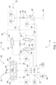
- Fig. 1 shows a schematically illustrated exemplary embodiment of the device 10 according to the invention for maintaining a Hydraulic supply of a commercial vehicle 12, in this case an agricultural tractor 14, not shown in detail.
- a hydraulic system 16 included in the agricultural tractor 14 is used to supply various hydraulic consumers 18, including a hydraulic steering or braking system 20, 22. More precisely, the hydraulic system 16 includes a hydraulic circuit 24 provided for operating the hydraulic consumers 18, which is operated by means of a Hydraulic pump 28, which is adjustable in terms of its delivery volume, is fed with hydraulic fluid from a reservoir 30 via a pressure control input 26.
- a first check valve 36 arranged between a delivery outlet 32 of the hydraulic pump 28 and a feed point 34 of the hydraulic circuit 24 prevents an undesirable loss of pressure in the hydraulic circuit 24 in the event of a failure of the hydraulic pump 28.
- the hydraulic pump 28 is driven by an internal combustion engine (not shown) present in the agricultural tractor 14.
- the device 10 further comprises a pressure accumulator 38, a loading valve 40 and a discharge valve 42.
- the two valves are 2/2-way valves that can be electrically actuated via associated solenoids 44, 46 formed, which are closed in the de-energized state.
- the pressure accumulator 38 is a piston accumulator 48 that can be preloaded by means of a gaseous operating medium.
- the piston accumulator 48 consists of a cylinder tube 50 designed as a high-pressure container, which is closed on its end faces with a respective cover 52, 54.
- a piston 56 that can be moved in the cylinder tube 50 divides the cylinder tube 50 into a gas space 58 and a liquid space 60.
- the pressurized gaseous operating medium in this case nitrogen gas, is supplied to the gas space 58 via a first connection 62 at the factory or during a workshop stay , supplied until a predetermined pre-filling pressure is reached.
- the piston accumulator 48 has a first pressure sensor 66 for detecting the current pre-filling pressure in the gas space 58 and a second pressure sensor 68 for detecting the current accumulator pressure in the liquid space 60.
- An inductive position sensor 70 is used to determine the current piston position within the cylinder tube 50 without contact. The sensor signals generated in this way are fed to a control unit 72 for evaluation.
- the storage volume of the pressure accumulator 38 differs from the illustration in Fig. 1 can also be divided into two piston accumulators 48 connected in parallel. This not only allows the use of comparatively small and therefore cost-effective piston accumulators 48, but also usually makes better use of the installation space available in the agricultural tractor 14.
- the piston accumulator 48 is charged by the hydraulic circuit 24 via a second check valve 74 by using the charging valve 40 to establish a pressure connection between the hydraulic circuit 24 and the pressure control input 26 of the hydraulic pump 28 via a sensor line 76.
- the charging valve 40 is actuated at the instigation of the control unit 72 depending on the current storage pressure in the liquid space 60 of the piston accumulator 48 detected by means of the second pressure sensor 68.
- the control unit 72 thus concludes that a charging process is necessary if it detects that the second pressure sensor 68 detected storage pressure and thus the hydraulic energy contained in the piston accumulator 48 is not sufficient to adequately ensure the operation of the hydraulic consumers 18. This is the case if the storage pressure falls below a minimum storage pressure that must be maintained.
- the minimum storage pressure to be maintained is specified in the range of 80 to 90% of the maximum storage pressure in the piston accumulator 48.
- the loading valve 40 is opened by the control unit 72 with the unloading valve 42 closed by energizing the associated solenoid 44, which results in the working pressure currently present in the hydraulic circuit 24 being transmitted to the pressure control input 26 of the hydraulic pump 28 via the sensor line 76 .
- the hydraulic pump 28 is currently in standby mode, this is in the order of 30 to 50 bar.
- this leads to the hydraulic pump 28 swinging out and an associated increase in the delivery volume in the direction of the hydraulic circuit 24 and thus the piston accumulator 48.
- the piston accumulator 48 is activated via the second check valve 74 until a maximum delivery pressure that can be achieved by the hydraulic pump 28 is reached filled with hydraulic fluid.
- the maximum storage pressure that can be achieved in this way is approximately 180 to 190 bar.
- the charging valve 40 is then closed again by the control unit 72 and the hydraulic pump 28 returns to standby mode.
- the second check valve 74 ensures that the maximum storage pressure built up during filling is maintained in the piston accumulator 48.
- a drop in the delivery pressure usually indicates a functional impairment, if not a failure, of the hydraulic pump 28. Accordingly, it is provided that the unloading valve 42 is actuated at the instigation of the control unit 72 depending on the current delivery pressure of the hydraulic pump 28 detected by a third pressure sensor 78. In other words, the unloading valve 42 is opened by the control unit 72 by energizing the associated solenoid 46 when it detects that the minimum delivery pressure of the hydraulic pump 28 that must be maintained is undershot.
- the minimum delivery pressure to be maintained is in the order of 90 to 95% of the working pressure intended for standby operation of the hydraulic pump 28.
- the hydraulic fluid located in the piston accumulator 48 can be discharged into the hydraulic circuit 24 bypassing the second check valve 74.
- the supply connection established in this way makes it possible, even if the hydraulic pump 28 fails, to continue to operate at least certain hydraulic consumers 18 of the agricultural tractor 14 in the manner usual for the operator for a limited period of time, which results from the hydraulic energy contained in the piston accumulator 48.
- the operator is given the opportunity to steer the agricultural tractor 14 safely into a suitable parking position and bring it to a standstill there.
- the supply connection is established via a pressure limiting element 80 arranged between the piston accumulator 48 and the hydraulic circuit 24. This is connected in series with the unloading valve 42 within the supply connection.
- the pressure limiting element 80 is a throttle valve that can be structurally integrated into the unloading valve 42.
- compliance with a predetermined, therefore defined working pressure in the hydraulic circuit 24 is desired, so that the pressure limiting element 80 is designed as a pressure control valve 82.
- the pressure control valve 82 is designed such that when the unloading valve 42 is open, a working pressure of approximately 65 bar is established in the hydraulic circuit 24.
- a pressure control input 84 communicates with the hydraulic circuit 24 via its own sensor line 86, bridging the unloading valve 42.
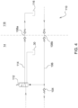
- Fig. 2 and 3 show optional modifications of the device 10 described above. The function is compared to that in Fig. 1 The embodiment shown remains unchanged, but the two modifications differ in terms of the type of operation of the loading and unloading valves 40, 42.
- valve actuation is not electrical by using a solenoid 44, but mechanically by direct pressure on an associated actuating element 88, which has a Control line 90 is acted upon by the storage pressure prevailing in the liquid space 60 of the piston accumulator 48.
- the sensor line 76 of the loading valve 40 cannot be connected directly to the hydraulic circuit 24, but rather via the unloading valve 42, which is now designed as a 3/2-way valve.
- the modification in Fig. 3 additionally provides a mechanical valve actuation of the unloading valve 42 instead of using the solenoid 46, this being done by direct pressure acting on an associated further actuating element 92, which is connected to the delivery output 32 of the hydraulic pump 28 via a further control line 94.
- the third pressure sensor 78 provided for detecting the delivery pressure is omitted in this case.
- control unit 72 is sensory in a predetermined storage state in accordance with a detected pre-filling pressure indicates a current energy storage capacity of the piston accumulator 48. If it turns out that a nominal pre-filling pressure specified for the predetermined storage state has not been reached, driver information is issued by the control unit 72 via a user interface 96. This is displayed in the form of a text instruction on a display 98 of the user interface 96 and indicates the need to make a corresponding pressure correction by refilling the gaseous operating medium.
- the nominal pre-filling pressure to be maintained refers to a completely or partially emptied storage state of the piston accumulator 48. If complete emptying is typically reserved for a maintenance-related visit to the workshop, partial emptying can in principle also be integrated into the normal operation of the agricultural tractor 14. In this context, it is conceivable to unload the piston accumulator 48 to a predefined accumulator pressure by opening the unloading valve 42 and to compare the resulting pre-filling pressure with a nominal pre-filling pressure specified for the relevant accumulator pressure.
- a (partial) emptying of the piston accumulator 48 required for storage diagnosis can be avoided if the control unit 72 is dependent on sensor-detected charging and/or discharging characteristics, which reflect the course of the piston position as a function of the pre-filling pressure, the storage pressure and an operating temperature a current energy storage capability of the piston accumulator 48 closes.
- the current energy storage capacity is then determined by comparing the recorded characteristics with corresponding nominal characteristics, which in turn result from the specifications of the piston accumulator 48 used.
- the latter are stored in a storage unit 100 that communicates with the control unit 72.
- the inductive position sensor 70 is used to sensorically detect the piston position, and the first or second pressure sensor 66, 68 is used to detect the pre-filling pressure or storage pressure.
- the operating temperature is also determined by sensory detection of an ambient temperature by means of a temperature sensor 102 connected to the control unit 72.
- control unit 72 draws conclusions about a current energy storage capacity of the piston accumulator 48 by comparing a sensor-detected pre-filling pressure with a sensor-detected piston position that corresponds to the respective pre-filling pressure.
- the current energy storage capacity results from an observed misalignment of the piston 56 compared to a nominal piston position specified for the relevant pre-filling pressure.
- the sensory detection of the piston position or the pre-filling pressure takes place by means of the inductive position sensor 70 or the first pressure sensor 66.
- the hydraulic circuit 24 is supplied with hydraulic fluid via a third check valve 104 via an inlet 106 from an over a releasable hydraulic clutch 108a, 108b can be supplied to a connectable additional hydraulic supply 110. More precisely, the hydraulic fluid is supplied via the feed point 34 of the hydraulic circuit 24.
- a switching valve 112 establishes a connection between a return line 114 of the hydraulic circuit 24 and a reservoir 116 of the additional hydraulic supply 110, in such a way that the im The amount of hydraulic fluid contained in the hydraulic circuit 24 of the agricultural tractor 14 remains essentially the same.
- This actuated state of the switching valve 112 is in Fig. 4 reproduced. This makes it possible for a hydraulic pressure source present in a tow vehicle 116 to externally supply the hydraulic steering and braking system 20, 22 connected to the hydraulic circuit 24 with energy.
- the towing vehicle 116 is, for example, another agricultural tractor, not shown in more detail.
Landscapes
- Engineering & Computer Science (AREA)
- Mechanical Engineering (AREA)
- Physics & Mathematics (AREA)
- Fluid Mechanics (AREA)
- General Engineering & Computer Science (AREA)
- Chemical & Material Sciences (AREA)
- Analytical Chemistry (AREA)
- Fluid-Pressure Circuits (AREA)
- Valves And Accessory Devices For Braking Systems (AREA)
- Control Of Fluid Gearings (AREA)
Abstract
Description
- Die Erfindung betrifft eine Vorrichtung zur Aufrechterhaltung einer Hydraulikversorgung eines Nutzfahrzeugs, umfassend eine über einen Drucksteuereingang bezüglich ihres Fördervolumens verstellbare Hydraulikpumpe zur Speisung eines Hydraulikkreises mit Hydraulikflüssigkeit.
- Ein derartiger Hydraulikkreis dient unter anderem in landwirtschaftlichen Nutzfahrzeugen der Energieversorgung diverser hydraulischer Verbraucher, zu denen auch sicherheitsrelevante Einrichtungen wie eine hydraulische Lenk- bzw. Bremsanlage gehören. Die betreffenden Einrichtungen werden hierbei mit unter Druck stehender Hydraulikflüssigkeit aus einem Hydraulikkreis des Nutzfahrzeugs versorgt, wobei die Zuführung der Hydraulikflüssigkeit mittels einer hydraulischen Hochdruckpumpe erfolgt. Genauer gesagt handelt es sich bei der hydraulischen Hochdruckpumpe um eine Verstellpumpe, deren Fördervolumen sich in Abhängigkeit eines an einen Drucksteuereingang übermittelten Steuerdrucks verändern lässt (sog. Load-Sensing-System bzw. LS-System), sodass eine Anpassung an den tatsächlichen Energiebedarf der zu versorgenden hydraulischen Verbraucher möglich ist.
- Da sich insbesondere eine hydraulische Lenk- bzw. Bremsanlage im Falle eines Ausfalls der hydraulischen Hochdruckpumpe manuell in der Regel nur schwer oder überhaupt nicht mehr betätigen lässt, verfügen manche Hydrauliksysteme in land- oder forstwirtschaftlichen Nutzfahrzeugen über eine elektrisch betriebene Hilfspumpe, die aus einer Fahrzeugbatterie mit Energie versorgt wird und so eine redundante Versorgung der betreffenden hydraulischen Verbraucher mit Hydraulikflüssigkeit erlaubt. Angesichts der insofern zu erbringenden Fördervolumina bzw. -drücke ist die Verwendung einer elektrisch betriebenen Hilfspumpe jedoch vergleichsweise aufwendig.
- Es ist daher Aufgabe der vorliegenden Erfindung, eine mit verhältnismäßig geringem Zusatzaufwand verwirklichbare Vorrichtung der eingangs genannten Art anzugeben.
- Diese Aufgabe wird durch eine Vorrichtung zur Aufrechterhaltung einer Hydraulikversorgung eines Nutzfahrzeugs mit den Merkmalen des Patentanspruchs 1 gelöst.
- Die Vorrichtung zur Aufrechterhaltung einer Hydraulikversorgung eines Nutzfahrzeugs umfasst eine über einen Drucksteuereingang bezüglich ihres Fördervolumens verstellbare Hydraulikpumpe zur Speisung eines Hydraulikkreises mit Hydraulikflüssigkeit und einen seitens des Hydraulikkreises über ein Rückschlagventil aufladbaren Druckspeicher, wobei mittels eines Ladeventils über eine Sensorleitung eine Druckverbindung zwischen dem Hydraulikkreis und dem Drucksteuereingang der Hydraulikpumpe herstellbar ist, und mittels eines Entladeventils durch Überbrückung des Rückschlagventils eine Versorgungsverbindung zwischen dem Druckspeicher und dem Hydraulikkreis herstellbar ist.
- Wird das Ladeventil geöffnet, so wird über die Sensorleitung der im Hydraulikkreis aktuell anliegende Arbeitsdruck an den Drucksteuereingang der Hydraulikpumpe übermittelt. Dieser liegt für den Fall, dass sich die Hydraulikpumpe gerade im Standby-Betrieb befindet, in der Größenordnung von 30 bis 50 bar. In der Folge führt dies zu einem Ausschwenken der Hydraulikpumpe sowie einer damit einhergehenden Erhöhung des Fördervolumens in Richtung des Hydraulikkreises und damit des Druckspeichers. Hierbei wird der Druckspeicher über das Rückschlagventil bis zum Erreichen eines von der Hydraulikpumpe erbringbaren maximalen Förderdrucks mit Hydraulikflüssigkeit befüllt. Der so erzielbare maximale Speicherdruck beträgt in etwa 180 bis 190 bar. Anschließend wird das Ladeventil wieder geschlossen, und die Hydraulikpumpe kehrt in den Standby-Betrieb zurück. Das Rückschlagventil stellt hierbei sicher, dass der beim Befüllen aufgebaute maximale Speicherdruck im Druckspeicher erhalten bleibt.
- Wird nun das Entladeventil geöffnet, so kann die im Druckspeicher befindliche Hydraulikflüssigkeit unter Umgehung des Rückschlagventils sich in den Hydraulikkreis entladen. Die derart hergestellte Versorgungsverbindung ermöglicht es, auch bei einem Ausfall der Hydraulikpumpe zumindest bestimmte hydraulische Verbraucher des Nutzfahrzeugs in für den Bediener gewohnter Weise für einen begrenzten Zeitraum, der sich aus der im Druckspeicher enthaltenen hydraulischen Energie ergibt, weiter zu betreiben. Für den Fall der hydraulischen Lenk- bzw. Bremsanlage erhält der Bediener so die Gelegenheit, das Nutzfahrzeug sicher in eine geeignete Parkposition zu lenken und dort zum Stillstand zu bringen.
- Aufgrund der Nutzung der ohnehin vorhandenen Hydraulikpumpe zum Laden des Druckspeichers lässt sich die erfindungsgemäße Vorrichtung mit vergleichsweise geringem Zusatzaufwand verwirklichen.
- Vorteilhafte Ausgestaltungen der erfindungsgemäßen Vorrichtung gehen aus den Unteransprüchen hervor.
- Um beim Öffnen des Entladeventils ein unkontrolliertes Entladen des Druckspeichers in den Hydraulikkreis zu verhindern, erfolgt die Herstellung der Versorgungsverbindung vorzugsweise über ein zwischen Druckspeicher und Hydraulikkreis angeordnetes Druckbegrenzungselement. Dieses ist innerhalb der Versorgungsverbindung in Serie mit dem Entladeventil geschaltet. Bei dem Druckbegrenzungselement handelt es sich im einfachsten Fall um ein Drosselventil, das insbesondere baulich in das Entladeventil integriert sein kann.
- Ist die Einhaltung eines vorgegebenen, mithin definierten Arbeitsdrucks im Hydraulikkreis erwünscht, so besteht auch die Möglichkeit, das Druckbegrenzungselement als Druckregelventil auszubilden. Das Druckregelventil wird derart ausgelegt, dass bei geöffnetem Entladeventil sich ein Arbeitsdruck von etwa 65 bar im Hydraulikkreis einstellt.
- Bevorzugt wird das Ladeventil bzw. das Entladeventil abhängig vom Förderdruck der Hydraulikpumpe bzw. vom Speicherdruck im Druckspeicher betätigt.
- So deutet ein Abfall des Förderdrucks in der Regel auf eine Funktionsbeeinträchtigung bis hin zum Ausfall der Hydraulikpumpe hin. Dementsprechend kann vorgesehen sein, dass das Entladeventil bei Unterschreiten eines vorgegebenen Mindestförderdrucks der Hydraulikpumpe eine geöffnete Stellung einnimmt. Der einzuhaltende Mindestförderdruck ist hierbei in der Größenordnung von 90 bis 95% des für den Standby-Betrieb der Hydraulikpumpe vorgesehenen Arbeitsdrucks im Hydraulikkreis vorgegeben.
- Umgekehrt kann auf die Notwendigkeit der Durchführung eines Ladevorgangs geschlossen werden, wenn erkannt wird, dass der Speicherdruck und damit die im Druckspeicher enthaltene hydraulische Energie nicht ausreicht, um den Betrieb der hydraulischen Verbraucher hinlänglich zu gewährleisten. Folglich ist es denkbar, dass das Ladeventil bei Unterschreiten eines für den Speicherdruck einzuhaltenden Mindestspeicherdrucks im Druckspeicher eine geöffnete Stellung einnimmt. Der einzuhaltende Mindestspeicherdruck ist hierbei im Bereich von 80 bis 90% des maximalen Speicherdrucks im Druckspeicher vorgegeben.
- Hierbei besteht die Möglichkeit, dass eine aufgrund einer Druckerfassung elektrisch und/oder mechanisch gesteuerte Betätigungseinrichtung zum Öffnen des Entladeventils und/oder des Ladeventils vorhanden ist. Im Falle einer elektrisch gesteuerten Betätigungseinrichtung kann ein herkömmlicher Drucksensor Verwendung finden, dessen Signale einer Kontrolleinheit zur Auswertung und elektrischen Ansteuerung eines zur Ventilbetätigung vorgesehenen Solenoids herangezogen werden. Bei Nutzung einer mechanisch gesteuerten Betätigungseinrichtung erfolgt die Ventilbetätigung hingegen durch unmittelbare Druckeinwirkung auf ein zugehöriges Stellelement.
- Bei dem Druckspeicher kann es sich um einen mittels eines gasförmigen Betriebsmediums vorspannbaren Kolbenspeicher handeln. Derartige Kolbenspeicher zeichnen sich durch eine besonders kompakte Bauform aus und bestehen üblicherweise aus einem als Hochdruckbehälter ausgebildeten Zylinderrohr, das an seinen Stirnseiten mit einem jeweiligen Deckel verschlossen ist. Ein in dem Zylinderrohr verschiebbarer Kolben unterteilt das Zylinderrohr in einen Gasraum und einen Flüssigkeitsraum. Zum Vorspannen des Kolbenspeichers wird dem Gasraum über einen ersten Anschluss das unter Druck stehende gasförmige Betriebsmedium, in der Regel Stickstoffgas, bis zum Erreichen eines vorgegebenen Vorfülldrucks zugeführt. Dies erfolgt werksseitig oder während eines Werkstattaufenthalts. Wird nun Hydraulikflüssigkeit aus dem Hydraulikkreis über einen zweiten Anschluss in den Flüssigkeitsraum gepresst, so verschiebt sich der Kolben in Richtung des Gasraums unter entsprechender reversibler Kompression des darin befindlichen gasförmigen Betriebsmediums. Die dabei geleistete Arbeit ist bestimmend für die im Kolbenspeicher gespeicherte bzw. speicherbare hydraulische Energie.
- An dieser Stelle sei erwähnt, dass grundsätzlich auch eine Verwendung andersartiger Speichertypen, wie beispielsweise eines Blasenspeichers oder dergleichen, denkbar ist. Aufgrund der gemessen an seiner kompakten Bauweise vergleichsweise hohen Ladekapazität wird jedoch ein Kolbenspeicher bevorzugt.
- Erfahrungsgemäß entweicht aufgrund von Leckagen das im Gasraum des Kolbenspeichers unter Druck stehende gasförmige Betriebsmedium im Laufe der Zeit. Dies führt zu einer schleichenden Abnahme des Vorfülldrucks und damit zu einer entsprechenden Degradation der gespeicherten bzw. speicherbaren hydraulischen Energie. Es kann daher vorgesehen sein, dass eine Kontrolleinheit nach Maßgabe eines in einem vorgegebenen Speicherzustand sensorisch erfassten Vorfülldrucks auf eine aktuelle Energiespeicherfähigkeit des Druckspeichers schließt. Ergibt sich, dass ein für den vorgegebenen Speicherzustand spezifizierter Nennvorfülldruck unterschritten ist, erfolgt die Ausgabe einer von der Kontrolleinheit über eine Nutzerschnittstelle veranlassten Fahrerinformation. Diese kann insbesondere in Form einer Textanweisung auf einem Display der Nutzerschnittstelle angezeigt werden und auf die Notwendigkeit hinweisen, eine entsprechende Druckkorrektur durch Nachfüllen des gasförmigen Betriebsmediums vorzunehmen.
- Der einzuhaltende Nennvorfülldruck kann sich hierbei auf einen vollständig oder teilweise entleerten Speicherzustand des Kolbenspeichers beziehen. Ist eine vollständige Entleerung typischerweise einem wartungsbedingten Werkstattaufenthalt vorbehalten, kann eine Teilentleerung grundsätzlich auch in den normalen Betrieb des Nutzfahrzeugs eingebunden werden. So ist es in diesem Zusammenhang vorstellbar, den Kolbenspeicher durch Öffnen des Entladeventils auf einen definierten Speicherdruck zu entladen sowie den sich daraus ergebenden Vorfülldruck mit einem für den betreffenden Speicherdruck spezifizierten Nennvorfülldruck zu vergleichen.
- Andererseits kann die Kontrolleinheit auch in Abhängigkeit sensorisch erfasster Lade- und/oder Entladekennlinien, die den Verlauf der Kolbenstellung als Funktion des Vorfülldrucks, des Speicherdrucks sowie einer Betriebstemperatur wiedergeben, auf eine aktuelle Energiespeicherfähigkeit des Kolbenspeichers schließen. Die aktuelle Energiespeicherfähigkeit ergibt sich dann durch Vergleich der erfassten Kennlinien mit entsprechenden Nennkennlinien, die sich ihrerseits aus den Spezifikationen des verwendeten Kolbenspeichers ergeben.
- Weiterhin kann auch vorgesehen sein, dass die Kontrolleinheit durch Vergleich eines sensorisch erfassten Vorfülldrucks mit einer sensorisch erfassten, mit dem jeweiligen Vorfülldruck korrespondierenden Kolbenstellung auf eine aktuelle Energiespeicherfähigkeit des Kolbenspeichers schließt. Die aktuelle Energiespeicherfähigkeit ergibt sich hierbei aus einer beobachteten Fehlstellung des Kolbens gegenüber einer für den betreffenden Vorfülldruck spezifizierten Nennkolbenstellung.
- Um das Nutzfahrzeug bei ausgefallener Hydraulikpumpe auch für den Fall eines unzulänglich geladenen Druckspeichers bis zur nächsten Werkstatt bewegen zu können, kann zur Verwirklichung eines Abschleppmodus vorgesehen sein, dass dem Hydraulikkreis über ein weiteres Rückschlagventil Hydraulikflüssigkeit insbesondere aus einer über eine lösbare Hydraulikkupplung anschließbaren Zusatzhydraulikversorgung zuführbar ist. Gleichzeitig stellt ein Umschaltventil abhängig von einer erkannten Hydraulikflüssigkeitszuführung eine Verbindung zwischen einem Rücklauf des Hydraulikkreises und einem Reservoir der Zusatzhydraulikversorgung her, vorzugsweise derart, dass die im Hydraulikkreis des Nutzfahrzeugs enthaltene Hydraulikflüssigkeitsmenge im Wesentlichen gleich bleibt. Unter anderem ermöglicht dies eine externe Versorgung der an dem Hydraulikkreis angeschlossenen hydraulischen Verbraucher seitens einer in einem Abschleppfahrzeug vorhandenen Hydraulikdruckquelle. Anstelle der Verwendung einer in einem Abschleppfahrzeugs vorhandenen Hydraulikdruckquelle ist es auch denkbar, den Druckspeicher mittels einer einfachen hydraulischen Handpumpe soweit aufzuladen, dass sich das Nutzfahrzeug auf einen Tieflader zum Weitertransport verbringen lässt. Die hydraulische Handpumpe kann hierbei mit Hydraulikflüssigkeit aus einem Reservoir des Nutzfahrzeugs gespeist werden.
- Die erfindungsgemäße Vorrichtung zur Aufrechterhaltung einer Hydraulikversorgung eines Nutzfahrzeugs wird im Folgenden anhand der beigefügten Zeichnungen näher beschrieben. Dabei beziehen sich identische Bezugszeichen auf übereinstimmende oder bezüglich ihrer Funktion vergleichbare Komponenten. Es zeigen:
- Fig. 1
- eine beispielhafte Ausführung der erfindungsgemäßen Vorrichtung zur Aufrechterhaltung einer Hydraulikversorgung eines Nutzfahrzeugs,
- Fig. 2
- eine erste konstruktive Abwandlung der in
Fig. 1 wiedergegebenen erfindungsgemäßen Vorrichtung, - Fig. 3
- eine zweite konstruktive Abwandlung der in
Fig. 1 wiedergegebenen erfindungsgemäßen Vorrichtung, und - Fig. 4
- ein optionaler Zusatzschaltkreis zur Verwirklichung eines Abschleppmodus durch Anschluss einer Zusatzhydraulikversorgung.
-
Fig. 1 zeigt ein schematisch dargestelltes Ausführungsbeispiel der erfindungsgemäßen Vorrichtung 10 zur Aufrechterhaltung einer Hydraulikversorgung eines Nutzfahrzeugs 12, vorliegend eines nicht näher wiedergegebenen landwirtschaftlichen Traktors 14. - Ein von dem landwirtschaftlichen Traktor 14 umfasstes Hydrauliksystem 16 dient der Versorgung diverser hydraulischer Verbraucher 18, unter anderem einer hydraulischen Lenk- bzw. Bremsanlage 20, 22. Genauer gesagt umfasst das Hydrauliksystem 16 einen zum Betrieb der hydraulischen Verbraucher 18 vorgesehenen Hydraulikkreis 24, der mittels einer über einen Drucksteuereingang 26 bezüglich ihres Fördervolumens verstellbaren Hydraulikpumpe 28 mit Hydraulikflüssigkeit aus einem Reservoir 30 gespeist wird. Ein zwischen einem Förderausgang 32 der Hydraulikpumpe 28 und einer Einspeisestelle 34 des Hydraulikkreises 24 angeordnetes erstes Rückschlagventil 36 beugt einem unerwünschten Druckverlust im Hydraulikkreis 24 bei einem Ausfall der Hydraulikpumpe 28 vor. Die Hydraulikpumpe 28 wird hierbei seitens eines im landwirtschaftlichen Traktor 14 vorhandenen Verbrennungsmotors (nicht gezeigt) angetrieben.
- Es sei angemerkt, dass neben den in
Fig. 1 dargestellten Komponenten auch weitere Hydraulikelemente vorhanden sein können. Die vorliegende Beschreibung soll sich jedoch aus Gründen der Verständlichkeit ausschließlich auf für die Funktion der Vorrichtung 10 erforderlichen Bestandteile beschränken. - Wie in
Fig. 1 erkennbar ist, umfasst die Vorrichtung 10 des Weiteren einen Druckspeicher 38, ein Ladeventil 40 sowie ein Entladeventil 42. Beispielsgemäß sind die beiden Ventile als über zugehörige Solenoide 44, 46 elektrisch betätigbare 2/2-Wegeventile ausgebildet, wobei diese in stromlosem Zustand geschlossen sind. - Bei dem Druckspeicher 38 handelt es sich um einen mittels eines gasförmigen Betriebsmediums vorspannbaren Kolbenspeicher 48. Der Kolbenspeicher 48 besteht aus einem als Hochdruckbehälter ausgebildeten Zylinderrohr 50, das an seinen Stirnseiten mit einem jeweiligen Deckel 52, 54 verschlossen ist. Ein in dem Zylinderrohr 50 verschiebbarer Kolben 56 unterteilt das Zylinderrohr 50 in einen Gasraum 58 und einen Flüssigkeitsraum 60. Zum Vorspannen des Kolbenspeichers 48 wird dem Gasraum 58 über einen ersten Anschluss 62 werksseitig bzw. während eines Werkstattaufenthalts das unter Druck stehende gasförmige Betriebsmedium, vorliegend Stickstoffgas, bis zum Erreichen eines vorgegebenen Vorfülldrucks zugeführt. Wird nun Hydraulikflüssigkeit aus dem Hydraulikkreis 24 über einen zweiten Anschluss 64 in den Flüssigkeitsraum 60 gepresst, so verschiebt sich der Kolben 56 in Richtung des Gasraums 58 unter entsprechender reversibler Kompression des darin befindlichen Stickstoffgases. Die dabei geleistete Arbeit ist bestimmend für die im Kolbenspeicher 48 gespeicherte bzw. speicherbare hydraulische Energie.
- Des Weiteren ist dem Kolbenspeicher 48 ein erster Drucksensor 66 zur Erfassung des aktuellen Vorfülldrucks im Gasraum 58 sowie ein zweiter Drucksensor 68 zur Erfassung des aktuellen Speicherdrucks im Flüssigkeitsraum 60 vorhanden. Ein induktiver Positionssensor 70 dient der berührungslosen Ermittlung der aktuellen Kolbenstellung innerhalb des Zylinderrohrs 50. Die solchermaßen erzeugten Sensorsignale werden einer Kontrolleinheit 72 zur Auswertung zugeführt.
- Es sei angemerkt, dass das Speichervolumen des Druckspeichers 38 abweichend von der Darstellung in
Fig. 1 auch auf zwei parallel geschaltete Kolbenspeicher 48 aufgeteilt sein kann. Dies erlaubt nicht nur eine Verwendung vergleichsweise kleiner und damit kostengünstiger Kolbenspeicher 48, sondern meist auch eine bessere Ausnutzung des im landwirtschaftlichen Traktor 14 zur Verfügung stehenden Bauraums. - Der Kolbenspeicher 48 wird seitens des Hydraulikkreises 24 über ein zweites Rückschlagventil 74 aufgeladen, indem mittels des Ladeventils 40 über eine Sensorleitung 76 eine Druckverbindung zwischen dem Hydraulikkreis 24 und dem Drucksteuereingang 26 der Hydraulikpumpe 28 hergestellt wird.
- Die Betätigung des Ladeventils 40 erfolgt auf Veranlassung der Kontrolleinheit 72 abhängig von dem mittels des zweiten Drucksensors 68 erfassten aktuellen Speicherdrucks im Flüssigkeitsraum 60 des Kolbenspeichers 48. So schließt die Kontrolleinheit 72 auf die Notwendigkeit der Durchführung eines Ladevorgangs, wenn diese erkennt, dass der mittels des zweiten Drucksensors 68 erfasste Speicherdruck und damit die im Kolbenspeicher 48 enthaltene hydraulische Energie nicht ausreicht, um den Betrieb der hydraulischen Verbraucher 18 hinlänglich zu gewährleisten. Dies ist dann der Fall, wenn für den Speicherdruck ein einzuhaltender Mindestspeicherdruck unterschritten ist. Der einzuhaltende Mindestspeicherdruck ist hierbei im Bereich von 80 bis 90% des maximalen Speicherdrucks im Kolbenspeicher 48 vorgegeben.
- Trifft dies zu, so wird das Ladeventil 40 von der Kontrolleinheit 72 bei geschlossenem Entladeventil 42 durch Bestromung des zugehörigen Solenoids 44 geöffnet, was dazu führt, dass über die Sensorleitung 76 der im Hydraulikkreis 24 aktuell anliegende Arbeitsdruck an den Drucksteuereingang 26 der Hydraulikpumpe 28 übermittelt wird. Dieser liegt für den Fall, dass sich die Hydraulikpumpe 28 gerade im Standby-Betrieb befindet, in der Größenordnung von 30 bis 50 bar. In der Folge führt dies zu einem Ausschwenken der Hydraulikpumpe 28 sowie einer damit einhergehenden Erhöhung des Fördervolumens in Richtung des Hydraulikkreises 24 und damit des Kolbenspeichers 48. Hierbei wird der Kolbenspeicher 48 über das zweite Rückschlagventil 74 bis zum Erreichen eines von der Hydraulikpumpe 28 erbringbaren maximalen Förderdrucks mit Hydraulikflüssigkeit befüllt. Der so erzielbare maximale Speicherdruck beträgt in etwa 180 bis 190 bar. Anschließend wird das Ladeventil 40 von der Kontrolleinheit 72 wieder geschlossen, und die Hydraulikpumpe 28 kehrt in den Standby-Betrieb zurück. Das zweite Rückschlagventil 74 stellt hierbei sicher, dass der beim Befüllen aufgebaute maximale Speicherdruck im Kolbenspeicher 48 erhalten bleibt.
- Soll andererseits die im Kolbenspeicher 48 enthaltende hydraulische Energie zum Betrieb der hydraulischen Verbraucher 18 abgerufen werden, wird mittels des Entladeventils 42 das zweite Rückschlagventil 74 überbrückt und so eine Versorgungsverbindung zwischen dem Flüssigkeitsraum 60 des Kolbenspeichers 48 und dem Hydraulikkreis 24 hergestellt.
- So deutet ein Abfall des Förderdrucks in der Regel auf eine Funktionsbeeinträchtigung, wenn nicht gar einen Ausfall der Hydraulikpumpe 28 hin. Dementsprechend ist vorgesehen, dass die Betätigung des Entladeventils 42 auf Veranlassung der Kontrolleinheit 72 abhängig von dem mittels eines dritten Drucksensors 78 erfassten aktuellen Förderdrucks der Hydraulikpumpe 28 erfolgt. Mit anderen Worten wird das Entladeventil 42 von der Kontrolleinheit 72 durch Bestromung des zugehörigen Solenoids 46 geöffnet, wenn diese erkennt, dass ein einzuhaltender Mindestförderdruck der Hydraulikpumpe 28 unterschritten ist. Der einzuhaltende Mindestförderdruck ist hierbei in der Größenordnung von 90 bis 95% des für den Standby-Betrieb der Hydraulikpumpe 28 vorgesehenen Arbeitsdrucks vorgegeben.
- Wird das Entladeventil 42 von der Kontrolleinheit 72 bei geschlossenen Ladeventil 40 geöffnet, so kann die im Kolbenspeicher 48 befindliche Hydraulikflüssigkeit unter Umgehung des zweiten Rückschlagventils 74 sich in den Hydraulikkreis 24 entladen. Die derart hergestellte Versorgungsverbindung ermöglicht es, auch bei einem Ausfall der Hydraulikpumpe 28 zumindest bestimmte hydraulische Verbraucher 18 des landwirtschaftlichen Traktors 14 in für den Bediener gewohnter Weise für einen begrenzten Zeitraum, der sich aus der im Kolbenspeicher 48 enthaltenen hydraulischen Energie ergibt, weiter zu betreiben. Für den Fall der hydraulischen Lenk- bzw. Bremsanlage 20, 22 erhält der Bediener so die Gelegenheit, den landwirtschaftlichen Traktor 14 sicher in eine geeignete Parkposition zu lenken und dort zum Stillstand zu bringen.
- Um beim Öffnen des Entladeventils 42 ein unkontrolliertes Entladen des Kolbenspeichers 48 in den Hydraulikkreis 24 zu verhindern, erfolgt die Herstellung der Versorgungsverbindung über ein zwischen Kolbenspeicher 48 und Hydraulikkreis 24 angeordnetes Druckbegrenzungselement 80. Dieses ist innerhalb der Versorgungsverbindung in Serie mit dem Entladeventil 42 geschaltet.
- Bei dem Druckbegrenzungselement 80 handelt es sich im einfachsten Fall um ein Drosselventil, das baulich in das Entladeventil 42 integriert sein kann. Vorliegend ist die Einhaltung eines vorgegebenen, mithin definierten Arbeitsdrucks im Hydraulikkreis 24 erwünscht, sodass das Druckbegrenzungselement 80 als Druckregelventil 82 ausgebildet ist. Das Druckregelventil 82 ist derart ausgelegt, dass bei geöffnetem Entladeventil 42 sich ein Arbeitsdruck von etwa 65 bar im Hydraulikkreis 24 einstellt. Hierzu kommuniziert ein Druckregeleingang 84 über eine eigene Sensorleitung 86 unter Überbrückung des Entladeventils 42 mit dem Hydraulikkreis 24.
-
Fig. 2 und3 zeigen optionale Abwandlungen der vorstehend beschriebenen Vorrichtung 10. Die Funktion ist gegenüber der inFig. 1 dargestellten Ausführung unverändert, die beiden Abwandlungen unterscheiden sich jedoch hinsichtlich der Art der Betätigung von Lade- und Entladeventil 40, 42. - So erfolgt im Falle des in
Fig. 2 dargestellten Ladeventils 40 die Ventilbetätigung nicht elektrisch durch Verwendung eines Solenoids 44, sondern mechanisch durch unmittelbare Druckeinwirkung auf ein zugehöriges Stellelement 88, das über eine Steuerleitung 90 mit dem im Flüssigkeitsraum 60 des Kolbenspeichers 48 herrschenden Speicherdruck beaufschlagt wird. Wie ferner zu erkennen ist, ist die Sensorleitung 76 des Ladeventils 40 nicht unmittelbar, sondern über das nunmehr als 3/2-Wegeventil ausgebildete Entladeventil 42 mit dem Hydraulickreis 24 verbindbar. - Die Abwandlung in
Fig. 3 sieht zusätzlich eine mechanische Ventilbetätigung des Entladeventils 42 anstelle der Verwendung des Solenoids 46 vor, wobei dies durch unmittelbare Druckeinwirkung auf ein zugehöriges weiteres Stellelement 92 erfolgt, das über eine weitere Steuerleitung 94 mit dem Förderausgang 32 der Hydraulikpumpe 28 in Verbindung steht. Der zur Erfassung des Förderdrucks vorgesehene dritte Drucksensor 78 entfällt in diesem Fall. - Erfahrungsgemäß entweicht aufgrund von Leckagen das im Gasraum 58 des Kolbenspeichers 48 unter Druck stehende Stickstoffgas im Laufe der Zeit. Dies führt zu einer schleichenden Abnahme des Vorfülldrucks im Gasraum 58 und damit zu einer entsprechenden Degradation der gespeicherten bzw. speicherbaren hydraulischen Energie. Die diesbezügliche Beurteilung des Zustands des Kolbenspeichers 48 erfolgt im Rahmen einer von der Kontrolleinheit 72 durchgeführten Speicherdiagnose. Insofern kann zwischen verschiedenen Vorgehensweisen gewählt werden.
- Im einfachsten Fall ist vorgesehen, dass die Kontrolleinheit 72 nach Maßgabe eines in einem vorgegebenen Speicherzustand sensorisch erfassten Vorfülldrucks auf eine aktuelle Energiespeicherfähigkeit des Kolbenspeichers 48 schließt. Ergibt sich, dass ein für den vorgegebenen Speicherzustand spezifizierter Nennvorfülldruck unterschritten ist, erfolgt die Ausgabe einer von der Kontrolleinheit 72 über eine Nutzerschnittstelle 96 veranlassten Fahrerinformation. Diese wird in Form einer Textanweisung auf einem Display 98 der Nutzerschnittstelle 96 angezeigt und weist auf die Notwendigkeit hin, eine entsprechende Druckkorrektur durch Nachfüllen des gasförmigen Betriebsmediums vorzunehmen.
- Der einzuhaltende Nennvorfülldruck bezieht sich hierbei auf einen vollständig oder teilweise entleerten Speicherzustand des Kolbenspeichers 48. Ist eine vollständige Entleerung typischerweise einem wartungsbedingten Werkstattaufenthalt vorbehalten, kann eine Teilentleerung grundsätzlich auch in den normalen Betrieb des landwirtschaftlichen Traktors 14 eingebunden werden. So ist es in diesem Zusammenhang vorstellbar, den Kolbenspeicher 48 durch Öffnen des Entladeventils 42 auf einen vordefinierten Speicherdruck zu entladen sowie den sich daraus ergebenden Vorfülldruck mit einem für den betreffenden Speicherdruck spezifizierten Nennvorfülldruck zu vergleichen.
- Andererseits lässt sich eine zur Speicherdiagnose erforderliche (Teil-) Entleerung des Kolbenspeichers 48 umgehen, wenn die Kontrolleinheit 72 in Abhängigkeit sensorisch erfasster Lade- und/oder Entladekennlinien, die den Verlauf der Kolbenstellung als Funktion des Vorfülldrucks, des Speicherdrucks sowie einer Betriebstemperatur wiedergeben, auf eine aktuelle Energiespeicherfähigkeit des Kolbenspeichers 48 schließt. Die aktuelle Energiespeicherfähigkeit ergibt sich dann durch Vergleich der erfassten Kennlinien mit entsprechenden Nennkennlinien, die sich ihrerseits aus den Spezifikationen des verwendeten Kolbenspeichers 48 ergeben. Letztere sind in einer mit der Kontrolleinheit 72 kommunizierenden Speichereinheit 100 hinterlegt. Zur sensorischen Erfassung der Kolbenstellung dient der induktive Positionssensor 70, von Vorfülldruck bzw. Speicherdruck der erste bzw. zweite Drucksensor 66, 68. Die Betriebstemperatur ergibt sich ferner durch sensorische Erfassung einer Umgebungstemperatur mittels eines mit der Kontrolleinheit 72 verbundenen Temperatursensors 102.
- Weiterhin kann auch vorgesehen sein, dass die Kontrolleinheit 72 durch Vergleich eines sensorisch erfassten Vorfülldrucks mit einer sensorisch erfassten, mit dem jeweiligen Vorfülldruck korrespondierenden Kolbenstellung auf eine aktuelle Energiespeicherfähigkeit des Kolbenspeichers 48 schließt. Die aktuelle Energiespeicherfähigkeit ergibt sich hierbei aus einer beobachteten Fehlstellung des Kolbens 56 gegenüber einer für den betreffenden Vorfülldruck spezifizierten Nennkolbenstellung. Die sensorische Erfassung der Kolbenstellung bzw. des Vorfülldrucks erfolgt mittels des induktiven Positionssensors 70 bzw. des ersten Drucksensors 66.
- Um den landwirtschaftlichen Traktor 14 bei ausgefallener Hydraulikpumpe 28 auch für den Fall eines unzulänglich geladenen Kolbenspeichers 48 bis zur nächsten Werkstatt bewegen zu können, ist zur Verwirklichung eines Abschleppmodus vorgesehen, dass dem Hydraulikkreis 24 über ein drittes Rückschlagventil 104 Hydraulikflüssigkeit über einen Zulauf 106 aus einer über eine lösbare Hydraulikkupplung 108a, 108b anschließbaren Zusatzhydraulikversorgung 110 zuführbar ist. Genauer gesagt erfolgt die Zuführung der Hydraulikflüssigkeit über die Einspeisestelle 34 des Hydraulikkreises 24. Gleichzeitig stellt ein Umschaltventil 112 abhängig von einer erkannten Hydraulikflüssigkeitszuführung eine Verbindung zwischen einem Rücklauf 114 des Hydraulikkreises 24 und einem Reservoir 116 der Zusatzhydraulikversorgung 110 her, und zwar derart, dass die im Hydraulikkreis 24 des landwirtschaftlichen Traktors 14 enthaltene Hydraulikflüssigkeitsmenge im Wesentlichen gleich bleibt. Dieser betätigte Zustand des Umschaltventils 112 ist in
Fig. 4 wiedergegeben. Dies ermöglicht seitens einer in einem Abschleppfahrzeug 116 vorhandenen Hydraulikdruckquelle, die an dem Hydraulikkreis 24 angeschlossene hydraulische Lenk- und Bremsanlage 20, 22 extern mit Energie zu versorgen. Bei dem Abschleppfahrzeug 116 handelt es sich beispielsweise um einen weiteren nicht näher wiedergegebenen landwirtschaftlichen Traktor.
Claims (11)
- Vorrichtung zur Aufrechterhaltung einer Hydraulikversorgung eines Nutzfahrzeugs, umfassend eine über einen Drucksteuereingang (26) bezüglich ihres Fördervolumens verstellbare Hydraulikpumpe (28) zur Speisung eines Hydraulikkreises (24) mit Hydraulikflüssigkeit, gekennzeichnet durch einen seitens des Hydraulikkreises (24) über ein Rückschlagventil (74) aufladbaren Druckspeicher (38), wobei mittels eines Ladeventils (40) über eine Sensorleitung (76) eine Druckverbindung zwischen dem Hydraulikkreis (24) und dem Drucksteuereingang (26) der Hydraulikpumpe (28) herstellbar ist, und mittels eines Entladeventils (42) durch Überbrückung des Rückschlagventils (74) eine Versorgungsverbindung zwischen dem Druckspeicher (38) und dem Hydraulikkreis (24) herstellbar ist.
- Vorrichtung nach Anspruch 1, dadurch gekennzeichnet, dass die Herstellung der Versorgungsverbindung über ein zwischen Druckspeicher (38) und Hydraulikkreis (24) angeordnetes Druckbegrenzungselement (80) erfolgt.
- Vorrichtung nach Anspruch 2, dadurch gekennzeichnet, dass das Druckbegrenzungselement (80) als Druckregelventil (82) zur Bereitstellung eines vorgegebenen Arbeitsdrucks im Hydraulikkreis (24) ausgebildet ist.
- Vorrichtung nach wenigstens einem der vorhergehenden Ansprüche, dadurch gekennzeichnet, dass das Entladeventil (42) bei Unterschreiten eines vorgegebenen Mindestförderdrucks der Hydraulikpumpe (28) eine geöffnete Stellung einnimmt.
- Vorrichtung nach wenigstens einem der vorhergehenden Ansprüche, dadurch gekennzeichnet, dass das Ladeventil (40) bei Unterschreiten eines für den Speicherdruck einzuhaltenden Mindestspeicherdrucks im Druckspeicher (38) eine geöffnete Stellung einnimmt.
- Vorrichtung nach wenigstens einem der Ansprüche 4 oder 5, dadurch gekennzeichnet, dass eine aufgrund einer Druckerfassung elektrisch und/oder mechanisch gesteuerte Betätigungseinrichtung (44, 46, 88, 92) zum Öffnen des Entladeventils (42) und/oder des Ladeventils (40) vorhanden ist.
- Vorrichtung nach einem der vorhergehenden Ansprüche, dadurch gekennzeichnet, dass es sich bei dem Druckspeicher (38) um einen mittels eines gasförmigen Betriebsmediums vorspannbaren Kolbenspeicher (48) handelt.
- Vorrichtung nach Anspruch 7, dadurch gekennzeichnet, dass eine Kontrolleinheit (72) nach Maßgabe eines in einem vorgegebenen Speicherzustand sensorisch erfassten Vorfülldrucks auf eine aktuelle Energiespeicherfähigkeit des Kolbenspeichers (48) schließt.
- Vorrichtung nach Anspruch 7, dadurch gekennzeichnet, dass eine Kontrolleinheit (72) in Abhängigkeit sensorisch erfasster Lade- und/oder Entladekennlinien, die den Verlauf der Kolbenstellung als Funktion des Vorfülldrucks, des Speicherdrucks sowie einer Betriebstemperatur wiedergeben, auf eine aktuelle Energiespeicherfähigkeit des Kolbenspeichers (48) schließt.
- Vorrichtung nach Anspruch 7, dadurch gekennzeichnet, dass eine Kontrolleinheit (72) durch Vergleich eines sensorisch erfassten Vorfülldrucks mit einer sensorisch erfassten, mit dem jeweiligen Vorfülldruck korrespondierenden Kolbenstellung auf eine aktuelle Energiespeicherfähigkeit des Kolbenspeichers (48) schließt.
- Vorrichtung nach wenigstens einem der vorhergehenden Ansprüche, dadurch gekennzeichnet, dass dem Hydraulikkreis (24) über ein weiteres Rückschlagventil (104) Hydraulikflüssigkeit insbesondere aus einer über eine lösbare Hydraulikkupplung (108a, 108b) anschließbaren Zusatzhydraulikversorgung (110) zuführbar ist, wobei ein Umschaltventil (112) abhängig von einer erkannten Hydraulikflüssigkeitszuführung gleichzeitig eine Verbindung zwischen einem Rücklauf (114) des Hydraulikkreises (24) und einem Reservoir der Zusatzhydraulikversorgung (110) herstellt, vorzugsweise derart, dass die im Hydraulickreis (24) des Nutzfahrzeugs (12) enthaltene Hydraulikflüssigkeitsmenge im Wesentlichen gleich bleibt.
Applications Claiming Priority (1)
| Application Number | Priority Date | Filing Date | Title |
|---|---|---|---|
| DE102022107684.9A DE102022107684A1 (de) | 2022-03-31 | 2022-03-31 | Vorrichtung zur Aufrechterhaltung einer Hydraulikversorgung eines Nutzfahrzeugs |
Publications (3)
| Publication Number | Publication Date |
|---|---|
| EP4253765A2 true EP4253765A2 (de) | 2023-10-04 |
| EP4253765A3 EP4253765A3 (de) | 2024-01-03 |
| EP4253765B1 EP4253765B1 (de) | 2025-08-20 |
Family
ID=85511226
Family Applications (1)
| Application Number | Title | Priority Date | Filing Date |
|---|---|---|---|
| EP23160529.6A Active EP4253765B1 (de) | 2022-03-31 | 2023-03-07 | Vorrichtung zur aufrechterhaltung einer hydraulikversorgung eines nutzfahrzeugs |
Country Status (3)
| Country | Link |
|---|---|
| US (1) | US12083974B2 (de) |
| EP (1) | EP4253765B1 (de) |
| DE (1) | DE102022107684A1 (de) |
Families Citing this family (1)
| Publication number | Priority date | Publication date | Assignee | Title |
|---|---|---|---|---|
| EP4614007A1 (de) * | 2024-03-06 | 2025-09-10 | Deere & Company | Verfahren zur zustandsüberprüfung eines hydrospeichers |
Family Cites Families (21)
| Publication number | Priority date | Publication date | Assignee | Title |
|---|---|---|---|---|
| US3820620A (en) | 1973-03-29 | 1974-06-28 | Deere & Co | Vehicle power steering electrohydraulic safety backup system |
| US4015681A (en) | 1975-11-06 | 1977-04-05 | International Harvester Company | Ground driven hydraulic emergency steering system |
| US3995711A (en) | 1976-03-18 | 1976-12-07 | Deere & Company | Vehicle power steering electro-hydraulic safety backup system |
| US4076096A (en) | 1976-11-24 | 1978-02-28 | Clark Equipment Company | Hydraulic steering system |
| US4160490A (en) | 1977-06-09 | 1979-07-10 | International Harvester Company | Auxiliary steering system |
| US4345660A (en) | 1979-12-26 | 1982-08-24 | Deere & Company | Vehicle emergency steering system |
| US4317499A (en) | 1979-12-26 | 1982-03-02 | Deere & Company | Vehicle emergency steering system |
| US4303089A (en) | 1980-10-14 | 1981-12-01 | Deere & Company | Steering including accumulator for supplying emergency reserve of fluid |
| US4326558A (en) | 1980-11-24 | 1982-04-27 | Deere & Company | Steering system including accumulator for supplying emergency reserve of fluid |
| US5201174A (en) | 1991-12-02 | 1993-04-13 | Deere & Company | Auxiliary hydraulic pump system |
| DE19917210A1 (de) * | 1999-04-16 | 2000-10-26 | Hydac Technology Gmbh | Verfahren zur Überwachung des Gas-Vorfülldruckes bei Hydrospeichern |
| US6935445B2 (en) | 2003-10-30 | 2005-08-30 | Deere & Company | Back-up steering system for track laying vehicles |
| WO2010117853A1 (en) * | 2009-04-06 | 2010-10-14 | Vanderbilt University | High energy density elastic accumulator and method of use thereof |
| US8561751B2 (en) * | 2011-08-09 | 2013-10-22 | Cnh America Llc | System for selectively charging and discharging a steering accumulator |
| DE102013200444A1 (de) * | 2013-01-15 | 2014-07-17 | Robert Bosch Gmbh | Verfahren zum Betreiben eines Hydrauliksystems |
| DE102014215567A1 (de) * | 2014-08-06 | 2016-02-11 | Robert Bosch Gmbh | Hydrostatischer Antrieb |
| GB2555472B (en) * | 2016-10-31 | 2020-02-05 | Caterpillar Sarl | Accumulator pressure monitoring system |
| US11346373B2 (en) * | 2017-01-10 | 2022-05-31 | Parker-Hannifin Corporation | Hydro-pneumatic accumulator with integrated nitrogen precharge regeneration system |
| SE542413C2 (en) * | 2018-02-27 | 2020-04-21 | Scania Cv Ab | Hydraulic Unit and Method for a hydraulic steering system of a vehicle |
| CN211852311U (zh) * | 2019-12-11 | 2020-11-03 | 西维智能控制技术(香河)有限公司 | 准确控氮气预充压力及蓄能器排油量的蓄能器系统 |
| DE102020200642B3 (de) * | 2020-01-21 | 2021-03-04 | Trelleborg Sealing Solutions Germany Gmbh | Kolbenspeichersystem sowie Überwachungsmodul und Überwachungsverfahren für ein Kolbenspeichersystem |
-
2022
- 2022-03-31 DE DE102022107684.9A patent/DE102022107684A1/de active Pending
-
2023
- 2023-03-07 EP EP23160529.6A patent/EP4253765B1/de active Active
- 2023-03-30 US US18/192,911 patent/US12083974B2/en active Active
Also Published As
| Publication number | Publication date |
|---|---|
| US12083974B2 (en) | 2024-09-10 |
| DE102022107684A1 (de) | 2023-10-05 |
| EP4253765B1 (de) | 2025-08-20 |
| US20230311796A1 (en) | 2023-10-05 |
| EP4253765A3 (de) | 2024-01-03 |
Similar Documents
| Publication | Publication Date | Title |
|---|---|---|
| DE10147118B4 (de) | Vorrichtung zur Diagnose eines Speichers auf der Grundlage des Fluiddrucks in seinem fluiddichten Zustand | |
| DE60101240T2 (de) | Selbstkalibrierendes System und Verfahren zum Steuern einer hydraulischen Vorrichtung | |
| DE112009002432T5 (de) | Leistungsentnahmesteuerungssystem angetrieben durch einen Elektrohybridfahrzeug-Antriebsmotor | |
| DE3101280A1 (de) | Fahrzeughoehenlageneinstellungs- oder fahrzeugnivelliersystem | |
| EP3724515B1 (de) | Druckluftversorgungsanlage zum betreiben einer pneumatikanlage, verfahren und fahrzeug | |
| EP3668766A1 (de) | Elektropneumatisches anhängerversorgungsmodul zum bereitstellen des anhängerversorgungsdrucks | |
| DE102008057859A1 (de) | Kraftstoffsparendes hydraulisches Servolenksystem | |
| EP1963118B1 (de) | Hydropneumatische achsfederung für fahrzeuge | |
| EP4253765B1 (de) | Vorrichtung zur aufrechterhaltung einer hydraulikversorgung eines nutzfahrzeugs | |
| DE102008021818B4 (de) | Verfahren zum Steuern einer Niveauregelanlage sowie Niveauregelanlage | |
| WO2010043594A1 (de) | Ventilanordnung und federanlage für ein fahrzeug | |
| EP1479584B1 (de) | Mehrkreisschutzventileinrichtung mit magnetventilgesteuerter Druckbegrenzersteuerung für druckluftbetätigte Aktuatoren eines Fahrzeugs | |
| DE3827507C2 (de) | Hydraulisches Bremssystem | |
| AT524855A4 (de) | Hydraulikaggregat zur Versorgung hydraulisch antreibbarer Rettungsgeräte | |
| DE19603593C1 (de) | Pneumatisches bzw. hydropneumatisches Federungssystem | |
| EP1022167A2 (de) | Niveauregelsystem für ein Kraftfahrzeug | |
| DE102015115082A1 (de) | Ventileinheit für pneumatische Anwendungen sowie Luftfederungsanlage | |
| DE3013853C2 (de) | ||
| EP3335917A1 (de) | Luftfederanlage für einen kraftwagen | |
| DE102004021242B4 (de) | Luftaufbereitungsanlage und Verfahren zum Versorgen einer Nutzkraftfahrzeugbremsanlage mit Druckluft | |
| DE2502308A1 (de) | Druckmittelsystem mit druckrueckkopplung | |
| EP1527974B1 (de) | Luftaufbereitungsanlage und Verfahren zum Versorgen einer Nutzkraftfahrzeugbremsanlage mit Druckluft | |
| DE4316339A1 (de) | Druckmittelversorgungseinrichtung | |
| DE4009687A1 (de) | Reifendruck-regeleinrichtung | |
| DE102020202907B4 (de) | Verfahren zum Betreiben eines Kupplungsbetätigungssystems |
Legal Events
| Date | Code | Title | Description |
|---|---|---|---|
| PUAI | Public reference made under article 153(3) epc to a published international application that has entered the european phase |
Free format text: ORIGINAL CODE: 0009012 |
|
| STAA | Information on the status of an ep patent application or granted ep patent |
Free format text: STATUS: THE APPLICATION HAS BEEN PUBLISHED |
|
| AK | Designated contracting states |
Kind code of ref document: A2 Designated state(s): AL AT BE BG CH CY CZ DE DK EE ES FI FR GB GR HR HU IE IS IT LI LT LU LV MC ME MK MT NL NO PL PT RO RS SE SI SK SM TR |
|
| PUAL | Search report despatched |
Free format text: ORIGINAL CODE: 0009013 |
|
| AK | Designated contracting states |
Kind code of ref document: A3 Designated state(s): AL AT BE BG CH CY CZ DE DK EE ES FI FR GB GR HR HU IE IS IT LI LT LU LV MC ME MK MT NL NO PL PT RO RS SE SI SK SM TR |
|
| RIC1 | Information provided on ipc code assigned before grant |
Ipc: F15B 11/16 20060101ALN20231128BHEP Ipc: A01B 69/00 20060101ALI20231128BHEP Ipc: B60T 13/12 20060101ALI20231128BHEP Ipc: B62D 49/00 20060101ALI20231128BHEP Ipc: B62D 5/30 20060101ALI20231128BHEP Ipc: B60T 17/00 20060101ALI20231128BHEP Ipc: B60D 1/62 20060101ALI20231128BHEP Ipc: F15B 19/00 20060101ALI20231128BHEP Ipc: F15B 1/027 20060101ALI20231128BHEP Ipc: F15B 1/033 20060101ALI20231128BHEP Ipc: F15B 20/00 20060101ALI20231128BHEP Ipc: F15B 1/24 20060101ALI20231128BHEP Ipc: F15B 1/02 20060101AFI20231128BHEP |
|
| STAA | Information on the status of an ep patent application or granted ep patent |
Free format text: STATUS: REQUEST FOR EXAMINATION WAS MADE |
|
| 17P | Request for examination filed |
Effective date: 20240703 |
|
| RBV | Designated contracting states (corrected) |
Designated state(s): AL AT BE BG CH CY CZ DE DK EE ES FI FR GB GR HR HU IE IS IT LI LT LU LV MC ME MK MT NL NO PL PT RO RS SE SI SK SM TR |
|
| GRAP | Despatch of communication of intention to grant a patent |
Free format text: ORIGINAL CODE: EPIDOSNIGR1 |
|
| STAA | Information on the status of an ep patent application or granted ep patent |
Free format text: STATUS: GRANT OF PATENT IS INTENDED |
|
| RIC1 | Information provided on ipc code assigned before grant |
Ipc: F15B 11/16 20060101ALN20250429BHEP Ipc: A01B 69/00 20060101ALI20250429BHEP Ipc: B60T 13/12 20060101ALI20250429BHEP Ipc: B62D 49/00 20060101ALI20250429BHEP Ipc: B62D 5/30 20060101ALI20250429BHEP Ipc: B60T 17/00 20060101ALI20250429BHEP Ipc: B60D 1/62 20060101ALI20250429BHEP Ipc: F15B 19/00 20060101ALI20250429BHEP Ipc: F15B 1/027 20060101ALI20250429BHEP Ipc: F15B 1/033 20060101ALI20250429BHEP Ipc: F15B 20/00 20060101ALI20250429BHEP Ipc: F15B 1/24 20060101ALI20250429BHEP Ipc: F15B 1/02 20060101AFI20250429BHEP |
|
| INTG | Intention to grant announced |
Effective date: 20250512 |
|
| GRAS | Grant fee paid |
Free format text: ORIGINAL CODE: EPIDOSNIGR3 |
|
| GRAA | (expected) grant |
Free format text: ORIGINAL CODE: 0009210 |
|
| STAA | Information on the status of an ep patent application or granted ep patent |
Free format text: STATUS: THE PATENT HAS BEEN GRANTED |
|
| AK | Designated contracting states |
Kind code of ref document: B1 Designated state(s): AL AT BE BG CH CY CZ DE DK EE ES FI FR GB GR HR HU IE IS IT LI LT LU LV MC ME MK MT NL NO PL PT RO RS SE SI SK SM TR |
|
| REG | Reference to a national code |
Ref country code: GB Ref legal event code: FG4D Free format text: NOT ENGLISH |
|
| REG | Reference to a national code |
Ref country code: CH Ref legal event code: EP |
|
| REG | Reference to a national code |
Ref country code: IE Ref legal event code: FG4D Free format text: LANGUAGE OF EP DOCUMENT: GERMAN |
|
| REG | Reference to a national code |
Ref country code: DE Ref legal event code: R096 Ref document number: 502023001595 Country of ref document: DE |
|
| REG | Reference to a national code |
Ref country code: NL Ref legal event code: MP Effective date: 20250820 |
|
| PG25 | Lapsed in a contracting state [announced via postgrant information from national office to epo] |
Ref country code: IS Free format text: LAPSE BECAUSE OF FAILURE TO SUBMIT A TRANSLATION OF THE DESCRIPTION OR TO PAY THE FEE WITHIN THE PRESCRIBED TIME-LIMIT Effective date: 20251220 |
|
| PG25 | Lapsed in a contracting state [announced via postgrant information from national office to epo] |
Ref country code: NO Free format text: LAPSE BECAUSE OF FAILURE TO SUBMIT A TRANSLATION OF THE DESCRIPTION OR TO PAY THE FEE WITHIN THE PRESCRIBED TIME-LIMIT Effective date: 20251120 |
|
| REG | Reference to a national code |
Ref country code: LT Ref legal event code: MG9D |
|
| PG25 | Lapsed in a contracting state [announced via postgrant information from national office to epo] |
Ref country code: PT Free format text: LAPSE BECAUSE OF FAILURE TO SUBMIT A TRANSLATION OF THE DESCRIPTION OR TO PAY THE FEE WITHIN THE PRESCRIBED TIME-LIMIT Effective date: 20251222 |
|
| PG25 | Lapsed in a contracting state [announced via postgrant information from national office to epo] |
Ref country code: FI Free format text: LAPSE BECAUSE OF FAILURE TO SUBMIT A TRANSLATION OF THE DESCRIPTION OR TO PAY THE FEE WITHIN THE PRESCRIBED TIME-LIMIT Effective date: 20250820 |
|
| PG25 | Lapsed in a contracting state [announced via postgrant information from national office to epo] |
Ref country code: HR Free format text: LAPSE BECAUSE OF FAILURE TO SUBMIT A TRANSLATION OF THE DESCRIPTION OR TO PAY THE FEE WITHIN THE PRESCRIBED TIME-LIMIT Effective date: 20250820 Ref country code: NL Free format text: LAPSE BECAUSE OF FAILURE TO SUBMIT A TRANSLATION OF THE DESCRIPTION OR TO PAY THE FEE WITHIN THE PRESCRIBED TIME-LIMIT Effective date: 20250820 |
|
| PG25 | Lapsed in a contracting state [announced via postgrant information from national office to epo] |
Ref country code: GR Free format text: LAPSE BECAUSE OF FAILURE TO SUBMIT A TRANSLATION OF THE DESCRIPTION OR TO PAY THE FEE WITHIN THE PRESCRIBED TIME-LIMIT Effective date: 20251121 |
|
| PG25 | Lapsed in a contracting state [announced via postgrant information from national office to epo] |
Ref country code: SE Free format text: LAPSE BECAUSE OF FAILURE TO SUBMIT A TRANSLATION OF THE DESCRIPTION OR TO PAY THE FEE WITHIN THE PRESCRIBED TIME-LIMIT Effective date: 20250820 |
|
| PG25 | Lapsed in a contracting state [announced via postgrant information from national office to epo] |
Ref country code: LV Free format text: LAPSE BECAUSE OF FAILURE TO SUBMIT A TRANSLATION OF THE DESCRIPTION OR TO PAY THE FEE WITHIN THE PRESCRIBED TIME-LIMIT Effective date: 20250820 |
|
| PG25 | Lapsed in a contracting state [announced via postgrant information from national office to epo] |
Ref country code: PL Free format text: LAPSE BECAUSE OF FAILURE TO SUBMIT A TRANSLATION OF THE DESCRIPTION OR TO PAY THE FEE WITHIN THE PRESCRIBED TIME-LIMIT Effective date: 20250820 Ref country code: BG Free format text: LAPSE BECAUSE OF FAILURE TO SUBMIT A TRANSLATION OF THE DESCRIPTION OR TO PAY THE FEE WITHIN THE PRESCRIBED TIME-LIMIT Effective date: 20250820 |
|
| PG25 | Lapsed in a contracting state [announced via postgrant information from national office to epo] |
Ref country code: RS Free format text: LAPSE BECAUSE OF FAILURE TO SUBMIT A TRANSLATION OF THE DESCRIPTION OR TO PAY THE FEE WITHIN THE PRESCRIBED TIME-LIMIT Effective date: 20251120 |
|
| PG25 | Lapsed in a contracting state [announced via postgrant information from national office to epo] |
Ref country code: ES Free format text: LAPSE BECAUSE OF FAILURE TO SUBMIT A TRANSLATION OF THE DESCRIPTION OR TO PAY THE FEE WITHIN THE PRESCRIBED TIME-LIMIT Effective date: 20250820 |
|
| PG25 | Lapsed in a contracting state [announced via postgrant information from national office to epo] |
Ref country code: SM Free format text: LAPSE BECAUSE OF FAILURE TO SUBMIT A TRANSLATION OF THE DESCRIPTION OR TO PAY THE FEE WITHIN THE PRESCRIBED TIME-LIMIT Effective date: 20250820 |
|
| PG25 | Lapsed in a contracting state [announced via postgrant information from national office to epo] |
Ref country code: DK Free format text: LAPSE BECAUSE OF FAILURE TO SUBMIT A TRANSLATION OF THE DESCRIPTION OR TO PAY THE FEE WITHIN THE PRESCRIBED TIME-LIMIT Effective date: 20250820 |
|
| PGFP | Annual fee paid to national office [announced via postgrant information from national office to epo] |
Ref country code: DE Payment date: 20260219 Year of fee payment: 4 |
|
| PGFP | Annual fee paid to national office [announced via postgrant information from national office to epo] |
Ref country code: AT Payment date: 20260301 Year of fee payment: 4 |
|
| PGFP | Annual fee paid to national office [announced via postgrant information from national office to epo] |
Ref country code: FR Payment date: 20260325 Year of fee payment: 4 |
|
| PG25 | Lapsed in a contracting state [announced via postgrant information from national office to epo] |
Ref country code: CZ Free format text: LAPSE BECAUSE OF FAILURE TO SUBMIT A TRANSLATION OF THE DESCRIPTION OR TO PAY THE FEE WITHIN THE PRESCRIBED TIME-LIMIT Effective date: 20250820 |
|
| PG25 | Lapsed in a contracting state [announced via postgrant information from national office to epo] |
Ref country code: SK Free format text: LAPSE BECAUSE OF FAILURE TO SUBMIT A TRANSLATION OF THE DESCRIPTION OR TO PAY THE FEE WITHIN THE PRESCRIBED TIME-LIMIT Effective date: 20250820 Ref country code: EE Free format text: LAPSE BECAUSE OF FAILURE TO SUBMIT A TRANSLATION OF THE DESCRIPTION OR TO PAY THE FEE WITHIN THE PRESCRIBED TIME-LIMIT Effective date: 20250820 |