EP4251007B1 - Glissière de tiroir téléscopique pour parties de meubles amovibles - Google Patents
Glissière de tiroir téléscopique pour parties de meubles amovibles Download PDFInfo
- Publication number
- EP4251007B1 EP4251007B1 EP21778471.9A EP21778471A EP4251007B1 EP 4251007 B1 EP4251007 B1 EP 4251007B1 EP 21778471 A EP21778471 A EP 21778471A EP 4251007 B1 EP4251007 B1 EP 4251007B1
- Authority
- EP
- European Patent Office
- Prior art keywords
- rail
- pull
- adjusting part
- differential
- roller
- Prior art date
- Legal status (The legal status is an assumption and is not a legal conclusion. Google has not performed a legal analysis and makes no representation as to the accuracy of the status listed.)
- Active
Links
Images


Classifications
-
- A—HUMAN NECESSITIES
- A47—FURNITURE; DOMESTIC ARTICLES OR APPLIANCES; COFFEE MILLS; SPICE MILLS; SUCTION CLEANERS IN GENERAL
- A47B—TABLES; DESKS; OFFICE FURNITURE; CABINETS; DRAWERS; GENERAL DETAILS OF FURNITURE
- A47B88/00—Drawers for tables, cabinets or like furniture; Guides for drawers
- A47B88/40—Sliding drawers; Slides or guides therefor
- A47B88/49—Sliding drawers; Slides or guides therefor with double extensible guides or parts
- A47B88/493—Sliding drawers; Slides or guides therefor with double extensible guides or parts with rollers, ball bearings, wheels, or the like
-
- A—HUMAN NECESSITIES
- A47—FURNITURE; DOMESTIC ARTICLES OR APPLIANCES; COFFEE MILLS; SPICE MILLS; SUCTION CLEANERS IN GENERAL
- A47B—TABLES; DESKS; OFFICE FURNITURE; CABINETS; DRAWERS; GENERAL DETAILS OF FURNITURE
- A47B88/00—Drawers for tables, cabinets or like furniture; Guides for drawers
- A47B88/40—Sliding drawers; Slides or guides therefor
- A47B88/44—Sequencing or synchronisation of drawer slides or functional units
- A47B88/447—Simultaneous movement of rails within drawer slides, i.e. with a coordination of movement with all rail elements moving at the same time
-
- A—HUMAN NECESSITIES
- A47—FURNITURE; DOMESTIC ARTICLES OR APPLIANCES; COFFEE MILLS; SPICE MILLS; SUCTION CLEANERS IN GENERAL
- A47B—TABLES; DESKS; OFFICE FURNITURE; CABINETS; DRAWERS; GENERAL DETAILS OF FURNITURE
- A47B88/00—Drawers for tables, cabinets or like furniture; Guides for drawers
- A47B88/40—Sliding drawers; Slides or guides therefor
- A47B88/473—Braking devices, e.g. linear or rotational dampers or friction brakes; Buffers; End stops
- A47B88/477—Buffers; End stops
-
- A—HUMAN NECESSITIES
- A47—FURNITURE; DOMESTIC ARTICLES OR APPLIANCES; COFFEE MILLS; SPICE MILLS; SUCTION CLEANERS IN GENERAL
- A47B—TABLES; DESKS; OFFICE FURNITURE; CABINETS; DRAWERS; GENERAL DETAILS OF FURNITURE
- A47B88/00—Drawers for tables, cabinets or like furniture; Guides for drawers
- A47B88/40—Sliding drawers; Slides or guides therefor
- A47B88/483—Sliding drawers; Slides or guides therefor with single extensible guides or parts
- A47B88/487—Sliding drawers; Slides or guides therefor with single extensible guides or parts with rollers, ball bearings, wheels, or the like
-
- A—HUMAN NECESSITIES
- A47—FURNITURE; DOMESTIC ARTICLES OR APPLIANCES; COFFEE MILLS; SPICE MILLS; SUCTION CLEANERS IN GENERAL
- A47B—TABLES; DESKS; OFFICE FURNITURE; CABINETS; DRAWERS; GENERAL DETAILS OF FURNITURE
- A47B88/00—Drawers for tables, cabinets or like furniture; Guides for drawers
- A47B88/50—Safety devices or the like for drawers
- A47B88/57—Safety devices or the like for drawers preventing complete withdrawal of the drawer
-
- A—HUMAN NECESSITIES
- A47—FURNITURE; DOMESTIC ARTICLES OR APPLIANCES; COFFEE MILLS; SPICE MILLS; SUCTION CLEANERS IN GENERAL
- A47B—TABLES; DESKS; OFFICE FURNITURE; CABINETS; DRAWERS; GENERAL DETAILS OF FURNITURE
- A47B88/00—Drawers for tables, cabinets or like furniture; Guides for drawers
- A47B88/40—Sliding drawers; Slides or guides therefor
- A47B88/423—Fastening devices for slides or guides
- A47B2088/4235—Fastening devices for slides or guides having a latch mechanism coupling or disconnecting a drawer with drawer side slide from the rest of the slide members
-
- A—HUMAN NECESSITIES
- A47—FURNITURE; DOMESTIC ARTICLES OR APPLIANCES; COFFEE MILLS; SPICE MILLS; SUCTION CLEANERS IN GENERAL
- A47B—TABLES; DESKS; OFFICE FURNITURE; CABINETS; DRAWERS; GENERAL DETAILS OF FURNITURE
- A47B88/00—Drawers for tables, cabinets or like furniture; Guides for drawers
- A47B88/40—Sliding drawers; Slides or guides therefor
- A47B88/407—Adjustably or detachably mounted drawers
-
- A—HUMAN NECESSITIES
- A47—FURNITURE; DOMESTIC ARTICLES OR APPLIANCES; COFFEE MILLS; SPICE MILLS; SUCTION CLEANERS IN GENERAL
- A47B—TABLES; DESKS; OFFICE FURNITURE; CABINETS; DRAWERS; GENERAL DETAILS OF FURNITURE
- A47B88/00—Drawers for tables, cabinets or like furniture; Guides for drawers
- A47B88/40—Sliding drawers; Slides or guides therefor
- A47B88/433—Drawers with a couple of pivotally retractable, roller-supporting arms at the rear of the drawer, e.g. for curved slides or guides
Definitions
- the invention relates to a differential pull-out guide for pull-out furniture parts, with a body rail that can be attached to a furniture body, a pull-out rail that can be attached to a pull-out furniture part and a middle rail arranged between the body rail and the pull-out rail, wherein the pull-out rail and the middle rail can be pulled out in a pull-out direction starting from a closed position of the differential pull-out guide to an open position of the differential pull-out guide and the pulling out of the middle rail from the body rail in the open position of the differential pull-out guide is limited by a stop element of the body rail, against which a stop surface of the middle rail runs, wherein on the middle rail in the area of the rear end of the middle rail an adjusting part is arranged between a release position, in which the middle rail can be tilted relative to the body rail about an axis lying horizontally and at right angles to the pull-out direction of the middle rail from a normal position to a tilting position, in which its rear end is lowered relative to the normal
- a differential extension guide of the type mentioned above is based on the EP 1 795 088 B1
- the middle rail moves synchronously with the pull-out rail when the pull-out rail is pulled out, covering half the distance of the pull-out rail.
- the middle rail has a load-transferring differential roller that rolls between the tracks of the pull-out rail and the body rail.
- all of the pull-out guide's rollers are rotatably mounted on the middle rail.
- the extension of the pull-out guide is limited by stops when the pull-out guide is in the open position, just as the pushing together of the pull-out guide is limited by stops when the pull-out guide is in the closed position.
- the body rail has a stop element against which a stop surface of the middle rail runs when the middle rail is extended.
- an adjusting part is arranged in the area of the rear end of the middle rail, which is adjustable between a release position and a lock position.
- the middle rail In the release position of the adjusting part, the middle rail can be tilted from a normal position to a tilted position relative to the body rail about a horizontal axis that is at right angles to the direction of extension of the middle rail. In the tilted position, the rear end of the middle rail is lowered compared to the normal position. This allows the stop surface of the middle rail to be lowered below the Stop element of the carcass rail can be guided past this and the middle rail can be pulled completely out of the carcass rail. When the adjusting part is in the locked position, the middle rail is blocked from tipping from the normal position to the tilt position, so that removal of the middle rail from the carcass rail is blocked.
- a roller is mounted on the adjusting part so that it can rotate about a horizontal axis that is at right angles to the pull-out direction and interacts with an upward-facing track on the carcass rail. If an attempt is made to tilt the middle rail from the normal position to the tilt position when the adjusting part is in the locked position, this roller on the adjusting part is pressed against the track on the carcass rail, which blocks tipping. In the release position, on the other hand, the adjusting part can pivot about a horizontal axis that is at right angles to the pull-out direction.
- a lateral guide roller is also mounted on the adjusting part so that it can rotate and interacts with a vertical web on the carcass rail. The lateral stability of the pull-out guide against a load on the middle rail towards the side facing away from the vertical bar of the body rail is thereby improved, particularly when the pull-out guide is open.
- pull-out guides with self-retraction devices in which the pull-out rail is automatically retracted over a final section of the insertion path. It is advantageous if such self-retraction devices are integrated into the pull-out guide.
- a pull-out guide with an integrated self-retraction device is, for example, available from the WO 2008/119091 A1
- the middle rail has in the area of its rear end, it has a cutout over part of its height. Above this cutout, at the rear end of the middle rail, there is, as usual, a roller which interacts with a downward-facing track on the body rail.
- auxiliary roller which interacts with the same tracks as the differential roller and which, when the pull-out guide is pushed in, can prevent the rear end of the middle rail and the rear end of the pull-out rail from tipping downwards, as is also usual with differential pull-outs. Due to the cutout in the middle rail behind the auxiliary roller, it is not possible to attach an adjusting part at this point which is adjustable between a release position and a locked position and which, in the release position, enables the middle rail to be tilted from a normal position to a tilted position in order to remove the middle rail from the body rail, and blocks such tilting in the locked position.
- a stop element arranged on the middle rail is thus itself adjustable between an active position, in which it interacts with a stop element of the body rail to limit the pulling out of the middle rail from the body rail, and a passive position, in which it is disengaged from the stop element of the body rail to enable the middle rail to be pulled out completely from the body rail.
- the design of an adjustable stop element is disadvantageous in terms of operation, construction and durability.
- the possible construction height of a self-retracting device is limited by the cutout at the rear end of the middle rail, which is only located in a lower part of the middle rail, so that limitations with regard to the design of the Self-retracting mechanism.
- the middle rail were shortened overall, the lateral stability of the extension guide would be reduced.
- the object of the invention is to provide an advantageous differential pull-out guide of the type mentioned at the beginning, which has as large an installation space as possible in the area of the rear end of the body rail for equipping the pull-out guide with a self-retracting device. According to the invention, this is achieved by a differential pull-out guide with the features of claim 1.
- the middle rail is shorter than the body rail and shorter than the pull-out rail and the rear end of the middle rail is offset forwards relative to the rear end of the body rail and relative to the rear end of the pull-out rail when the differential pull-out guide is pushed in.
- the lateral guide roller of the adjusting part arranged in the area of the rear end of the middle rail not only interacts with the vertical web of the body rail, but also interacts with a vertical web of the pull-out rail on the side of the adjusting part opposite the vertical web of the body rail, or an additional lateral guide roller is rotatably mounted on the base body of the adjusting part, which interacts with the vertical web of the pull-out rail on the side of the adjusting part opposite the vertical web of the body rail.
- the design according to the invention creates an installation space in the area of the rear end of the body rail provided, which extends essentially over the entire height of the carcass rail.
- the differential pull-out guide according to the invention has advantageous lateral stability in the closed position and over a first section of the extension, so that the pull-out furniture part guided by the differential pull-out guide is stable against a force acting in the sense of a rotation about a vertical axis.
- the running properties of the pull-out guide are improved by reducing friction.
- the body rail and the pull-out rail are the same length and, in the closed position of the differential pull-out guide, are flush with each other at both their front and rear ends.
- a roller is rotatably mounted on the base body of the adjusting part, which roller rolls at least starting from the closed state of the differential pull-out guide over a first section of the extension of the differential pull-out guide between an upwardly directed track of the body rail and a downwardly directed track of the pull-out rail and a load can be transferred from the pull-out rail to the body rail via this section of the extension of the differential pull-out guide.
- This also makes it possible to dispense with a further auxiliary roller arranged between the differential roller and the adjusting part, which over a first section of the extension of the differential extension guide between the upwardly directed track of the body rail and the downwardly directed track of the extension rail.
- the roller of the adjusting part could also only interact with the upwardly directed track of the body rail and an additional roller could be rotatably mounted on the base body of the adjusting part, which interacts with the downwardly directed track of the extension rail at least over a first section of the extension of the differential extension guide starting from the closed position of the differential extension guide, whereby a load can be transferred from the extension rail to the body rail via the additional roller, the base body of the adjusting part and the roller.
- the actuating part in the release position, can be pivoted relative to the central rail about a horizontal pivot axis that is at a right angle to the extension direction in order to lower the rear end of the central rail, and in the blocking position it is blocked against pivoting about the pivot axis, the pivot axis of the actuating part being arranged further forward than the lateral guide roller of the actuating part (13).
- the pivot axis of the actuating part can be moved relative to the central rail.
- the differential pull-out guide is designed as a roller pull-out.
- rollers which ensure that the rails can be moved relative to one another, are rotatably mounted on the rails.
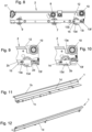
- the differential pull-out guide has a body rail 3, a pull-out rail 1 and a middle rail 2 arranged between the body rail 3 and the pull-out rail 1, whereby in the exemplary embodiment all rollers are rotatably mounted on the middle rail 2.
- the carcass rail 3 is used for attachment to a furniture carcass 4, of which only Fig. 3 a section is indicated with dashed lines.
- the pull-out rail 1 is used for attachment to a pull-out furniture part 5, for example a drawer, from which only Fig. 3 a section is indicated by dashed lines.
- the pull-out furniture part 5 rests on a lower horizontal bar 1c of the pull-out rail 1, which is connected to the lower end of a vertical bar 1d of the pull-out rail 1.
- the lower horizontal bar 1c could also be omitted and the pull-out furniture part 5 could be attached to the vertical bar 1d.
- a horizontal bar 1b of the pull-out rail 1 is connected to the upper end of the vertical bar 1d. If the lower horizontal bar 1c is present, the lower horizontal bar 1c and the horizontal bar 1b on opposite sides of the vertical bar 1d.
- the body rail 3 has a vertical bar 3d, to which an upper horizontal bar 3c and a lower horizontal bar 3b are connected at the upper and lower ends, so that the body rail has a C-shaped cross-section.
- the middle rail 2 has a vertical web 2a on which rollers of the differential pull-out guide are rotatably mounted.
- the middle rail additionally has a horizontal web 2c, which is connected on one side to the lower end of the vertical web 2a and on the opposite side to the lower end of a vertical section 2b of the middle rail 2, the height of which is less than half the height of the vertical web 2a.
- the rails 1-3 are guided synchronously, i.e. when the pull-out rail 1 is pulled out from the middle rail 2 in a pull-out direction 6, the middle rail 2 moves synchronously relative to the body rail 3 in the pull-out direction 6.
- the middle rail 2 thereby covers half the distance of the pull-out rail 1 relative to the body rail 3.
- the pull-out guide When the differential pull-out guide is completely pushed together, the pull-out guide is in the closed position, in which the middle rail 2 has a pushed-in position in which it is completely pushed into the body rail 3, and the pull-out rail 1 has a pushed-in position in which it is completely pushed into the middle rail 2.
- the pull-out guide When the pull-out guide is completely pulled apart, the pull-out guide is in the open position, in which the Middle rail 2 has an extended position in which it is completely pulled out of the carcass rail, and the pull-out rail 1 has an extended position in which it is completely pulled out of the middle rail 2.
- a rotating differential roller 7 arranged on the middle rail, which rolls between a downward-facing track 1a of the pull-out rail 1 arranged on the underside of the horizontal bar 1b of the pull-out rail and an upward-facing track 3a of the body rail 3 arranged on the top side of the lower horizontal bar 3b of the body rail 3 and in doing so transfers part of the load of the pull-out rail 1 directly to the body rail 3.
- the differential roller 7 has a play in the vertical direction. In the closed position of the pull-out guide, the differential roller is located in the area of the longitudinal center of the pull-out guide.
- the middle rail 2 has a support roller 8 which is rotatably mounted on the vertical web 2a of the middle rail 2 and which, in the extended position of the pull-out rail 1, can support the rear end of the pull-out rail 1 against pivoting upwards.
- all rollers are arranged on the middle rail 2, as is preferred in differential pull-out guides.
- a roller 9 which interacts with the upwardly directed track 3a of the third rail 3 and, in a rear region of the middle rail 2, a roller 10 which interacts with a downwardly directed track of the body rail 3 arranged on the underside of an upper horizontal web 3c of the body rail 3.
- the roller 10 is rotatably mounted on the vertical web 2a of the middle rail 2.
- the differential roller 7 and the roller 9 are rotatably mounted between a lower section of the vertical web 2a and the opposite vertical section 2b of the middle rail 2.
- the lower end of the vertical web 2a and the vertical section 2b are connected to opposite edges of the lower horizontal web 2c of the middle rail 2.
- the lower section of the vertical web 2a, the lower horizontal web 2c and the vertical section 2b together form a U-shaped section of the middle rail 2 when viewed from the front or in the cross section of the middle rail.
- a stop element 11 of the body rail is used, with which a stop surface 12 of the middle rail 2 interacts.
- the stop element 11 of the body rail 3 is formed by a tongue punched out of the upper horizontal web 3c and bent downwards.
- the stop surface 12 of the middle rail 2 is formed by the front surface of a section of the vertical web 2a of the middle rail 2 that projects upwards in the area of the rear end of the middle rail 2. In the extended position of the middle rail 2, the stop surface 12 runs against the Stop element 11, as shown in Fig. 24 is evident.
- an adjusting part 13 is arranged on the middle rail 2, which is explained in more detail below and which, in a locking position, prevents the middle rail 2 from lowering its rear end from a normal position into a tilting position (cf. Fig. 21 ) in which the stop surface 12 can be guided under the stop element 11.
- the insertion of the middle rail 2 into the pull-out rail 1 is limited by a contact surface 3e of the body rail 3, against which the adjusting part 13 runs in the inserted position of the middle rail 2, as will be explained in more detail below.
- a locking part 17 is mounted at the front end of the middle rail 2 so as to be rotatable about a horizontal axis, which in the locking position shown in the figures prevents the pull-out rail 1 from being unhooked from the middle rail 2.
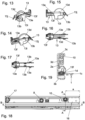
- the adjusting part 13 is adjustable between a locking position (cf. Fig. 1-3 , 6-8 , 23 and 24 ) and a release position (cf. Fig. 9, 10 , 21 and 22 ) adjustably mounted.
- the release position the actuating part 13 can be pivoted about a pivot axis 14 that is horizontal and at a right angle to the pull-out direction 6.
- the locked position the pivoting of the actuating part 13 about the pivot axis 14 is blocked.
- the pivot axis 14 is formed by axle pins 13a of the actuating part 13, which are arranged on the outer sides of two arms 13b projecting forwards of a base body 13e of the actuating part 13.
- the axle pins 13a engage in elongated holes 15 in the middle rail 2.
- the elongated holes 15 are arranged in opposite vertical sections of the middle rail 2. One of these vertical sections, in which one of the elongated holes 15 is arranged, is formed by the lower section of the vertical web 2a of the middle rail 2.
- the opposite elongated hole 15 is arranged in the vertical section 2b of the middle rail.
- the elongated holes 15 extend at least essentially in a horizontal direction parallel to the pull-out direction ("essentially” in this context means a deviation of less than +/- 10°).
- the axle pins 13a can be moved in the elongated holes 15, which means that the pivot axis 14 can be moved.
- the actuating part 13 is in the locking position.
- the actuating part 13 is in the release position.
- the elongated holes 15 preferably have constrictions in a central area.
- the arms 13b can be inserted into In order to hold the axle pins 13a even more securely in the elongated holes 15, the arms 13b could be connected at their front ends by a spring element that counteracts compression.
- this contact point 13c is formed by the lowest point of a roller 13d of the actuating part 13 that is rotatably mounted on the base body 13e of the actuating part 13, as is preferred.
- the roller 13d is arranged in the space between the arms 13b.
- the lower horizontal web 2c of the middle rail 2 has a cutout in the area of the roller 13d.
- the embodiment shown could also be modified in such a way that an additional auxiliary roller is rotatably mounted on the center rail 2 in the area between the differential roller and the actuating part 13, which interacts with the same tracks as the differential roller 7.
- auxiliary rollers are known in conventional differential pull-out guides.
- the roller 13d rotatably mounted on the actuating part could also be omitted.
- the contact point 13d formed by the lowest point of the roller the lower end of a contact section 13i of the base body 13e would then form such a contact point.
- the base body 13e shown in the embodiment can therefore be used both with the roller 13d as shown and in applications without the roller 13d.
- this retaining surface 2d is formed by a rearwardly projecting extension of the vertical section 2b of the middle rail 2, located above the base body 13e of the actuating part 13.
- the contact section 13i could also have a projection projecting forwards, which interacts with a projection of the central rail which projects in the area next to the roller 13d from the lower end of the vertical section 2b in the direction of the roller 13d and which forms the retaining surface.
- the base body 13e comes out of engagement with the retaining surface 2d (i.e. lies behind it). This enables the control element to pivot about the pivot axis 14 while raising the contact point 13c. This allows the center rail 2 to be tilted from its normal position, which it assumes in the locking position of the control element 13, to a tilted position in which the rear end of the center rail 2 is lowered compared to the normal position.
- Fig. 23 The normal position of the middle rail 2 is shown with the control element 13 in the locked position.
- the control element is in the release position adjusted, but the middle rail is still in the normal position.
- tongue-shaped spring elements 13j of the base body 13e come into contact with the section of the lower horizontal web 2c of the middle rail 2 located in front of the cutout for the roller 13d and are elastically deflected. These spring elements 13j therefore cause a restoring force on the actuating part 13 in the sense of pivoting it back into the position in which it can be adjusted to the locking position. At least one spring element for restoring the pivoted actuating part could also be designed in a different way.
- the middle rail 2 is pushed into the carcass rail 3 with the adjusting part 13 in the release position, the base body 13e of the adjusting part 13 runs against the contact surface 3e of the carcass rail 3 shortly before the middle rail 2 reaches the pushed-in position, cf. Fig. 22 If the middle rail 2 is retracted further into the retracted position, the actuating part 13 is moved into the locking position by the contact surface 3e, cf. Fig. 23 .
- the contact surface 3e is formed by a tab punched out of the vertical web 3d and bent over.
- the roller 13d of the actuating part 13 rolls over a first section of the extension of the differential extension guide, starting from the closed position of the differential extension guide, between the upwardly directed track 3a of the body rail and the downwardly directed track 1a of the extension rail 1. If a section of the extension rail 1 located behind the differential roller 7 is loaded sufficiently, a load can be transferred from the extension rail 1 directly to the body rail 3 via the roller 13e.
- the roller 13d also takes on the function of an auxiliary roller arranged between the differential roller and the rear end of the body rail in conventional differential extension guides, which is omitted here.
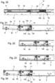
- the middle rail 2 is shorter than the body rail 3 and the pull-out rail 1 and the rear end of the middle rail is offset forwards in relation to the rear end of the body rail 3 and the rear end of the pull-out rail 1 when the differential pull-out guide is closed. This is particularly good from Fig. 18 visible.
- a self-retracting device 16 integrated into the differential pull-out guide is only available in Fig. 18 highly schematically indicated by dashed lines.
- Self-retracting devices for pull-out guides including those that are integrated into the pull-out guide, are known and common.
- Such self-retracting devices usually have a spring-loaded tilting slide.
- the pull-out guide When the pull-out guide is pulled out, this is adjusted from a basic position, which the tilting slide assumes in the closed position of the pull-out guide, against the spring force of a driver arranged on the pull-out rail, into a waiting position.
- the driver of the pull-out rail decouples from the tilting slide by tilting the tilting slide and the tilting slide remains in the waiting position by resting on a retaining surface of the self-retracting device.
- the driver of the pull-out rail couples to the tilting slide and tilts it, whereby the tilting slide is released from the retaining surface.
- the spring-loaded tilting slide then pulls the pull-out rail into the pushed-in position. This process can be dampened by a damper.
- the pull-out rail 1 and the body rail 3 are the same length, as is preferred, and in the closed position of the differential pull-out guide they are flush with each other at both their front ends and their rear ends. It would also be conceivable and possible for the body rail 3 to be shorter than the pull-out rail 1 and to be offset forwards relative to the rear end of the pull-out rail in the closed position of the pull-out guide.
- the distance a of the rear end of the middle rail 2 from the rear end of the body rail 3 is in the closed position Position of the differential pull-out guide preferably more than 5% of the length of the body rail 3, particularly preferably more than 10%. In the exemplary embodiment, the distance a is approximately 15% of the length of the body rail 3.
- a lateral guide roller 13f is mounted on the base body 13e of the adjusting part 13 so as to be rotatable about a vertical axis.
- This lateral guide roller 13f interacts on one side of the adjusting part 13 with the vertical web 3d of the body rail 3 and on the opposite side of the adjusting part 13 with the vertical web 1d of the pull-out rail 1 (see in particular Fig. 19 and 20 ).
- good lateral stability of the pull-out guide is achieved even in the closed position of the pull-out guide and over a first section of the pull-out guide.
- the first section of the extension of the differential extension guide, over which the side guide roller interacts with both the vertical web 3d of the body rail 3 and the vertical web 1d of the extension rail 1, is preferably 10% to 30% of the total extension distance.
- Fig. 21-23 The insertion of the middle rail 2 removed from the carcass rail 3 into the carcass rail 3 is described below using the Fig. 21-23 explained (in these figures, the safety part 17 on the middle rail is not shown).
- the adjusting part 13 is first adjusted to the release position.
- the middle rail 2 is then pivoted into the tilting position and its rear end is inserted into the space between the horizontal bars 3b, 3c of the body rail, whereby the adjusting part 13 is pivoted about the pivot axis 14.
- Fig. 21 The state is shown when the stop surface 12 of the middle rail 2 has just been passed under the stop element 11 of the body rail 3.
- Fig. 22 The state is shown in which the base body 13e runs against the contact surface 3e of the body rail 3. This is the case shortly before the middle rail 2 reaches the pushed-in position. If the middle rail is now fully pushed into the pushed-in position, the actuating part 13 is moved from the contact surface 3e into the locking position, cf. Fig. 23 This adjustment of the control element 13 from the release position to the locking position takes place automatically when the middle rail is pushed into the pushed-in position.
- the stop surface 12 of the middle rail 2 runs into the stop element 11 of the carcass rail 3 in the pulled-out position of the middle rail, whereby further pulling out of the middle rail 2 is blocked, cf. Fig. 24 .
- the middle rail 2 is moved to the extended position accordingly Fig. 24 pulled out and the control part 13 is moved to the release position.
- the stop surface 12 of the middle rail 2 can be guided under the stop element 11 of the body rail 3, whereupon the middle rail 2 can be pulled out completely from the body rail 3.
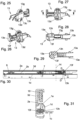
- a second embodiment of the invention with a modified control element is described below with reference to the Fig. 25-31 explained. Apart from the differences described below, the design corresponds to that of the first embodiment and the description of the first embodiment and the modifications described therein can be used in an analogous manner.
- the roller 13d of the adjusting part 13 is smaller here and only interacts with the upwardly directed track 3a of the lower horizontal bar 3b of the body rail 3.
- an additional roller 13g is mounted on the base body 13e of the adjusting part 13 so that it can rotate about a horizontal axis that is perpendicular to the pull-out direction 6. This only interacts with the downwardly directed track 1a of the horizontal bar 1b of the pull-out rail 1.
- the possible load transfer from the pull-out rail 1 to the body rail 3 via the adjusting part 13 takes place in this embodiment via the additional roller 13g, the base body 13e and the roller 13d.
- the lateral guide roller 13f is smaller in this embodiment and only interacts with the vertical web 3d of the body rail 3, see in particular Fig. 30 and 31
- an additional lateral guide roller 13h is provided, which only interacts with the vertical web 1d of the pull-out rail 1. This is particularly evident from the Fig. 30 and 31 visible. If, in the closed position of the pull-out guide and in a first section of the pull-out guide, a force directed towards the body rail 3 acts on the rear end of the pull-out rail 1, this force is transferred to the vertical web 3d of the body rail 3 via the lateral guide roller 13f, the base body 13e and the additional lateral guide roller 13h.
- the first section of the extension of the differential extension guide, over which the additional lateral guide roller 13h interacts with the vertical web 1d of the extension rail 1, is preferably 10% to 30% of the total extension distance.
- the adjusting part 13 could have a roller 13d, which interacts with the opposite tracks of the pull-out rail and body rail, and a lateral guide roller and additional lateral guide roller, one of which interacts with the vertical web of the body rail and the other with the vertical web of the pull-out rail, or the adjusting part could have a roller and an additional roller, one of which interacts with the track of the body rail and the other with the track of the pull-out rail, and a lateral guide roller, which interacts with both the vertical web of the body rail and interacts with the vertical bar of the pull-out rail.
Landscapes
- Drawers Of Furniture (AREA)
Claims (10)
- Guide d'extraction différentiel pour parties de meuble extractibles, avec une glissière de corps (3) pouvant être montée sur un corps de meuble (4), une glissière d'extraction (1) pouvant être montée sur une partie de meuble extractible (5) et une glissière centrale (2) disposée entre la glissière de corps (3) et la glissière d'extraction (1), la glissière d'extraction (1) et la glissière centrale (2) pouvant être extraites dans une direction d'extraction (6) en partant d'une position fermée du guide d'extraction différentiel jusqu'à une position ouverte du guide d'extraction différentiel, et l'extraction de la glissière centrale (2) hors de la glissière de corps (3) dans la position ouverte du guide d'extraction différentiel étant assurée par un élément de butée (11) de la glissière de corps (3), contre lequel une surface de butée (12) de la glissière centrale (2) vient buter, une pièce de réglage (13) étant montée sur la glissière centrale (2) dans la zone de l'extrémité arrière de la glissière centrale (2) entre une position de libération, dans laquelle la glissière centrale (2) peut être basculée par rapport à la glissière de corps (3) autour d'un axe horizontal et perpendiculaire à la direction d'extraction (6) de la glissière centrale (2) d'une position normale dans une position de basculement, dans laquelle son extrémité arrière est abaissée par rapport à la position normale et la surface de butée (12) de la glissière centrale (2) peut passer sous l'élément de butée (11) de la glissière de corps (3) pour extraire la glissière centrale (2) de la glissière de corps (3), et une position de blocage, dans laquelle le rail central (2) est bloqué contre un basculement de la position normale dans la position de basculement, et un galet de guidage latéral (13f), qui coopère avec une entretoise verticale (3d) de la glissière de corps (3), étant monté de manière à pouvoir tourner sur un corps de base (13e) de la pièce de réglage (13), caractérisé, que la glissière centrale (2) est plus courte que la glissière de corps (3) et plus courte que la glissière d'extraction (1) et que l'extrémité arrière de la glissière centrale (2), à l'état inséré du guide d'extraction différentiel, est décalée par rapport à l'extrémité arrière de la glissière de corps (3) et par rapport à l'extrémité arrière de la glissière d'extraction (1). (1) est décalé vers l'avant et que le galet de guidage latéral (13f) de l'élément de réglage (13) coopère avec une nervure verticale (1d) de la glissière d'extraction (1) sur le côté de l'élément de réglage (13) opposé à la nervure verticale (3d) de la glissière de corps (3) ou qu'un galet de guidage latéral supplémentaire (13f) est monté sur le corps de base (13e) de l'élément de réglage (13).galet de guidage latéral (13h), qui coopère avec l'âme verticale (1d) de la glissière d'extraction (1) sur le côté de la pièce de réglage (13) opposé à l'âme verticale (3d) de la glissière de corps (3).
- Guide d'extraction différentiel selon la revendication 1, caractérisé en ce que le rail central (2) comporte un rouleau différentiel (7) de transmission de charge, monté rotatif, qui possède un jeu dans la direction verticale par rapport au rail central (2) et qui, de l'état rentré à l'état sorti du guide d'extraction différentiel, roule entre une voie de roulement (3a), orientée vers le haut, du rail de corps (3) et une voie de roulement (1a), orientée vers le bas, du rail d'extraction (1).
- Guide d'extraction différentiel selon la revendication 2, caractérisé en ce qu'un galet de roulement (13d) est monté à rotation sur le corps de base (13e) de la pièce de réglage (13), qui roule au moins sur une première section de l'extraction du guide d'extraction différentiel en partant de la position fermée du guide d'extraction différentiel entre la voie de roulement (3a) orientée vers le haut de la glissière de corps (3) et la voie de roulement (1a) orientée vers le bas de la glissière d'extraction (1) et par lequel une charge peut être transmise de la glissière d'extraction (1) à la glissière de corps (3), ou un galet de roulement (13d) et un galet de roulement supplémentaire (13g) sont montés rotatifs sur le corps de base (13e) de l'élément de réglage (13), parmi lesquels le galet de roulement (13d) coopère avec la voie de roulement (3a) orientée vers le haut de la glissière de corps (3) et le galet de roulement supplémentaire (13g) coopère avec la voie de roulement (1a) orientée vers le bas de la glissière d'extraction (1) au moins sur une première partie de l'extraction du guide d'extraction différentiel en partant de la position fermée du guide d'extraction différentiel, une charge pouvant être transmise de la glissière d'extraction (1) à la glissière de corps (3) par l'intermédiaire du galet de roulement supplémentaire (13g), du corps de base (13e) et du galet de roulement (13d).
- Guide d'extraction différentiel selon l'une des revendications 1 à 3, caractérisé en ce que l'élément de réglage (13) peut pivoter autour d'un axe de pivotement (14) horizontal et perpendiculaire à la direction d'extraction dans la position de libération pour abaisser l'extrémité arrière du rail central (2) par rapport au rail central (2) et est bloqué contre un pivotement autour de l'axe de pivotement (14) dans la position de blocage.
- Guide d'extraction différentiel selon la revendication 4, caractérisé en ce que l'axe de pivotement (14) de l'élément de réglage (13) peut être déplacé par rapport au rail central (2) pour le réglage de l'élément de réglage (13) entre la position de blocage et la position de libération, le corps de base (13e) de l'élément de réglage (13) étant en prise avec une surface de retenue (2d) du rail central (2) dans la position de blocage de l'élément de réglage (13) pour bloquer la capacité de pivotement de l'élément de réglage (13).
- Guide d'extraction différentiel selon la revendication 5, caractérisé en ce que, lors du coulissement de la glissière d'extraction (1) de la position ouverte à la position fermée, l'élément de réglage (13) se trouvant dans la position de libération, l'élément de réglage (13) vient buter contre une surface de butée (3e) de la glissière de corps (3), qui déplace l'élément de réglage (13) dans la position de blocage.
- Guide d'extraction différentiel selon la revendication 5 ou 6, caractérisé en ce que l'élément de réglage (13) comporte deux bras (13b) faisant saillie vers l'avant, sur les côtés desquels, éloignés l'un de l'autre, est disposé respectivement un tourillon (13a), ces tourillons (13a), qui forment l'axe de pivotement (14) de l'élément de réglage (13), s'engageant dans des trous oblongs (15), qui sont disposés dans des sections verticales opposées (2b) du rail central (2).
- Guide d'extraction différentiel selon l'une des revendications 1 à 7, caractérisé en ce que, lors d'un pivotement de l'élément de réglage (13) avec abaissement de l'extrémité arrière du rail central (2), au moins un élément de ressort (13j) est dévié élastiquement et provoque une force de rappel sur l'élément de réglage (13) dans le sens d'un pivotement en retour dans la position dans laquelle l'élément de réglage (13) peut être déplacé dans la position de blocage.
- Guide d'extraction différentiel selon l'une des revendications 3 à 8, caractérisé en ce que, dans la zone du rail central (2) située derrière le galet différentiel (7), seul le galet de roulement (13d) de la pièce de réglage (13) coopère avec le chemin de roulement (3a) du rail de corps (3) orienté vers le haut.
- Guide d'extraction différentiel selon l'une des revendications 1 à 9, caractérisé en ce que le rail central (2) comporte tous les galets de roulement du guide d'extraction (1).
Applications Claiming Priority (2)
| Application Number | Priority Date | Filing Date | Title |
|---|---|---|---|
| ATA258/2020A AT523910B1 (de) | 2020-11-27 | 2020-11-27 | Differentialausziehführung für ausziehbare Möbelteile |
| PCT/EP2021/075825 WO2022111878A1 (fr) | 2020-11-27 | 2021-09-20 | Glissière de tiroir téléscopique pour parties de meubles amovibles |
Publications (2)
| Publication Number | Publication Date |
|---|---|
| EP4251007A1 EP4251007A1 (fr) | 2023-10-04 |
| EP4251007B1 true EP4251007B1 (fr) | 2024-10-16 |
Family
ID=77951725
Family Applications (1)
| Application Number | Title | Priority Date | Filing Date |
|---|---|---|---|
| EP21778471.9A Active EP4251007B1 (fr) | 2020-11-27 | 2021-09-20 | Glissière de tiroir téléscopique pour parties de meubles amovibles |
Country Status (7)
| Country | Link |
|---|---|
| US (1) | US12226013B2 (fr) |
| EP (1) | EP4251007B1 (fr) |
| CN (1) | CN116568182B (fr) |
| AT (1) | AT523910B1 (fr) |
| ES (1) | ES2999542T3 (fr) |
| PL (1) | PL4251007T3 (fr) |
| WO (1) | WO2022111878A1 (fr) |
Families Citing this family (2)
| Publication number | Priority date | Publication date | Assignee | Title |
|---|---|---|---|---|
| US12342934B2 (en) * | 2023-11-30 | 2025-07-01 | Tanko Organize Company | Slide rail structure with buffer seat |
| DE102024117471B3 (de) * | 2024-06-20 | 2025-06-12 | Fulterer Ag & Co. Kg | Differentialauszug mit Selbsteinzugsvorrichtung |
Family Cites Families (15)
| Publication number | Priority date | Publication date | Assignee | Title |
|---|---|---|---|---|
| DE2641375C3 (de) * | 1976-09-15 | 1982-04-29 | Kumepa Patentgesellschaft Et., Vaduz | Schubladenführung mit Endanschlag |
| AT6364U1 (de) * | 2002-08-29 | 2003-09-25 | Blum Gmbh Julius | Ausziehführungsgarnitur für schubladen |
| AT502661B1 (de) * | 2005-12-06 | 2007-05-15 | Fulterer Gmbh | Differentialausziehführung für ausziehbare möbelteile |
| AT505053B1 (de) * | 2007-04-02 | 2009-02-15 | Fulterer Gmbh | Rollen-differentialausziehführung |
| AT506062B1 (de) * | 2007-12-27 | 2009-06-15 | Fulterer Gmbh | Rollen-ausziehführung |
| AT510258B1 (de) * | 2010-09-10 | 2012-03-15 | Fulterer Gmbh | Ausziehführung |
| AT514559B1 (de) | 2013-08-19 | 2015-02-15 | Fulterer Gmbh | Ausziehführung |
| JP5725219B1 (ja) * | 2014-01-29 | 2015-05-27 | 日本電気株式会社 | スライドレールユニット |
| AT518980B1 (de) * | 2016-10-28 | 2018-03-15 | Blum Gmbh Julius | Schubladenausziehführung |
| AT519838B1 (de) * | 2017-03-31 | 2019-05-15 | Fulterer Ag & Co Kg | Ausziehführung für ein aus einem Möbelkorpus ausziehbares Möbelteil |
| AT520805B1 (de) | 2017-12-15 | 2020-10-15 | Fulterer Ag & Co Kg | Ausziehführung |
| AT520766B1 (de) * | 2017-12-21 | 2023-04-15 | Blum Gmbh Julius | Schubladenausziehführung |
| US11583078B2 (en) * | 2020-08-04 | 2023-02-21 | Accuride International, Inc. | Extendable drawer slide |
| AT523907B1 (de) * | 2020-10-28 | 2022-01-15 | Fulterer Ag & Co Kg | Ausziehführung |
| AT523909B1 (de) * | 2020-11-16 | 2022-01-15 | Fulterer Ag & Co Kg | Ausziehführung |
-
2020
- 2020-11-27 AT ATA258/2020A patent/AT523910B1/de active
-
2021
- 2021-09-20 EP EP21778471.9A patent/EP4251007B1/fr active Active
- 2021-09-20 ES ES21778471T patent/ES2999542T3/es active Active
- 2021-09-20 PL PL21778471.9T patent/PL4251007T3/pl unknown
- 2021-09-20 WO PCT/EP2021/075825 patent/WO2022111878A1/fr not_active Ceased
- 2021-09-20 US US18/038,771 patent/US12226013B2/en active Active
- 2021-09-20 CN CN202180079592.9A patent/CN116568182B/zh active Active
Also Published As
| Publication number | Publication date |
|---|---|
| US12226013B2 (en) | 2025-02-18 |
| CN116568182A (zh) | 2023-08-08 |
| US20240032690A1 (en) | 2024-02-01 |
| ES2999542T3 (en) | 2025-02-26 |
| CN116568182B (zh) | 2025-11-21 |
| PL4251007T3 (pl) | 2025-03-31 |
| WO2022111878A1 (fr) | 2022-06-02 |
| AT523910A4 (de) | 2022-01-15 |
| EP4251007A1 (fr) | 2023-10-04 |
| AT523910B1 (de) | 2022-01-15 |
Similar Documents
| Publication | Publication Date | Title |
|---|---|---|
| EP2777432B1 (fr) | Commande d'extraction pour un élément de meuble pouvant être extrait d'un corps de meuble | |
| EP2916688B1 (fr) | Glissière télescopique de tiroir | |
| EP2074909B1 (fr) | Guidage d'extraction de rouleaux | |
| EP3381325B1 (fr) | Guide d'extraction pour une pièce de meuble pouvant être tirée d'une structure de meuble de base | |
| EP2994011A1 (fr) | Guidage télescopique | |
| EP1820422B1 (fr) | Système de guidage de coulissement pour parties de meuble qui peuvent coulisser hors du corps d'un meuble | |
| EP4251007B1 (fr) | Glissière de tiroir téléscopique pour parties de meubles amovibles | |
| EP1795088B1 (fr) | Glissière différentielle pour parties de meuble extensibles | |
| AT517479B1 (de) | Schubladenausziehführung | |
| EP4236725B1 (fr) | Glissière télescopique | |
| EP4243652B1 (fr) | Guide d'extraction | |
| EP1532892A1 (fr) | Dispositif de retrait automatique | |
| EP4164450B1 (fr) | Dispositif auto-rétractable | |
| EP3369345B1 (fr) | Surface de couchage pourvue de dispositif de réglage de l'inclinaison | |
| EP3897295B1 (fr) | Dispositif de fermeture automatique | |
| EP4217562B1 (fr) | Dispositif de blocage d'extraction pour tiroirs | |
| EP4182528B1 (fr) | Dispositif de blocage de sortie pour tiroirs | |
| EP3928660B1 (fr) | Dispositif d'auto-traction pour une pièce de meuble télescopique |
Legal Events
| Date | Code | Title | Description |
|---|---|---|---|
| STAA | Information on the status of an ep patent application or granted ep patent |
Free format text: STATUS: UNKNOWN |
|
| STAA | Information on the status of an ep patent application or granted ep patent |
Free format text: STATUS: THE INTERNATIONAL PUBLICATION HAS BEEN MADE |
|
| PUAI | Public reference made under article 153(3) epc to a published international application that has entered the european phase |
Free format text: ORIGINAL CODE: 0009012 |
|
| STAA | Information on the status of an ep patent application or granted ep patent |
Free format text: STATUS: REQUEST FOR EXAMINATION WAS MADE |
|
| 17P | Request for examination filed |
Effective date: 20230627 |
|
| AK | Designated contracting states |
Kind code of ref document: A1 Designated state(s): AL AT BE BG CH CY CZ DE DK EE ES FI FR GB GR HR HU IE IS IT LI LT LU LV MC MK MT NL NO PL PT RO RS SE SI SK SM TR |
|
| DAV | Request for validation of the european patent (deleted) | ||
| DAX | Request for extension of the european patent (deleted) | ||
| GRAP | Despatch of communication of intention to grant a patent |
Free format text: ORIGINAL CODE: EPIDOSNIGR1 |
|
| STAA | Information on the status of an ep patent application or granted ep patent |
Free format text: STATUS: GRANT OF PATENT IS INTENDED |
|
| INTG | Intention to grant announced |
Effective date: 20240712 |
|
| GRAS | Grant fee paid |
Free format text: ORIGINAL CODE: EPIDOSNIGR3 |
|
| GRAA | (expected) grant |
Free format text: ORIGINAL CODE: 0009210 |
|
| STAA | Information on the status of an ep patent application or granted ep patent |
Free format text: STATUS: THE PATENT HAS BEEN GRANTED |
|
| AK | Designated contracting states |
Kind code of ref document: B1 Designated state(s): AL AT BE BG CH CY CZ DE DK EE ES FI FR GB GR HR HU IE IS IT LI LT LU LV MC MK MT NL NO PL PT RO RS SE SI SK SM TR |
|
| REG | Reference to a national code |
Ref country code: GB Ref legal event code: FG4D Free format text: NOT ENGLISH |
|
| REG | Reference to a national code |
Ref country code: CH Ref legal event code: EP Ref country code: DE Ref legal event code: R096 Ref document number: 502021005528 Country of ref document: DE |
|
| REG | Reference to a national code |
Ref country code: IE Ref legal event code: FG4D Free format text: LANGUAGE OF EP DOCUMENT: GERMAN |
|
| P01 | Opt-out of the competence of the unified patent court (upc) registered |
Free format text: CASE NUMBER: APP_59377/2024 Effective date: 20241031 |
|
| REG | Reference to a national code |
Ref country code: LT Ref legal event code: MG9D |
|
| REG | Reference to a national code |
Ref country code: NL Ref legal event code: MP Effective date: 20241016 |
|
| REG | Reference to a national code |
Ref country code: ES Ref legal event code: FG2A Ref document number: 2999542 Country of ref document: ES Kind code of ref document: T3 Effective date: 20250226 |
|
| PG25 | Lapsed in a contracting state [announced via postgrant information from national office to epo] |
Ref country code: NL Free format text: LAPSE BECAUSE OF FAILURE TO SUBMIT A TRANSLATION OF THE DESCRIPTION OR TO PAY THE FEE WITHIN THE PRESCRIBED TIME-LIMIT Effective date: 20241016 |
|
| PG25 | Lapsed in a contracting state [announced via postgrant information from national office to epo] |
Ref country code: NL Free format text: LAPSE BECAUSE OF FAILURE TO SUBMIT A TRANSLATION OF THE DESCRIPTION OR TO PAY THE FEE WITHIN THE PRESCRIBED TIME-LIMIT Effective date: 20241016 |
|
| PG25 | Lapsed in a contracting state [announced via postgrant information from national office to epo] |
Ref country code: IS Free format text: LAPSE BECAUSE OF FAILURE TO SUBMIT A TRANSLATION OF THE DESCRIPTION OR TO PAY THE FEE WITHIN THE PRESCRIBED TIME-LIMIT Effective date: 20250216 Ref country code: PT Free format text: LAPSE BECAUSE OF FAILURE TO SUBMIT A TRANSLATION OF THE DESCRIPTION OR TO PAY THE FEE WITHIN THE PRESCRIBED TIME-LIMIT Effective date: 20250217 Ref country code: HR Free format text: LAPSE BECAUSE OF FAILURE TO SUBMIT A TRANSLATION OF THE DESCRIPTION OR TO PAY THE FEE WITHIN THE PRESCRIBED TIME-LIMIT Effective date: 20241016 |
|
| PG25 | Lapsed in a contracting state [announced via postgrant information from national office to epo] |
Ref country code: FI Free format text: LAPSE BECAUSE OF FAILURE TO SUBMIT A TRANSLATION OF THE DESCRIPTION OR TO PAY THE FEE WITHIN THE PRESCRIBED TIME-LIMIT Effective date: 20241016 |
|
| PG25 | Lapsed in a contracting state [announced via postgrant information from national office to epo] |
Ref country code: BG Free format text: LAPSE BECAUSE OF FAILURE TO SUBMIT A TRANSLATION OF THE DESCRIPTION OR TO PAY THE FEE WITHIN THE PRESCRIBED TIME-LIMIT Effective date: 20241016 |
|
| PG25 | Lapsed in a contracting state [announced via postgrant information from national office to epo] |
Ref country code: NO Free format text: LAPSE BECAUSE OF FAILURE TO SUBMIT A TRANSLATION OF THE DESCRIPTION OR TO PAY THE FEE WITHIN THE PRESCRIBED TIME-LIMIT Effective date: 20250116 |
|
| PG25 | Lapsed in a contracting state [announced via postgrant information from national office to epo] |
Ref country code: LV Free format text: LAPSE BECAUSE OF FAILURE TO SUBMIT A TRANSLATION OF THE DESCRIPTION OR TO PAY THE FEE WITHIN THE PRESCRIBED TIME-LIMIT Effective date: 20241016 Ref country code: GR Free format text: LAPSE BECAUSE OF FAILURE TO SUBMIT A TRANSLATION OF THE DESCRIPTION OR TO PAY THE FEE WITHIN THE PRESCRIBED TIME-LIMIT Effective date: 20250117 |
|
| PG25 | Lapsed in a contracting state [announced via postgrant information from national office to epo] |
Ref country code: RS Free format text: LAPSE BECAUSE OF FAILURE TO SUBMIT A TRANSLATION OF THE DESCRIPTION OR TO PAY THE FEE WITHIN THE PRESCRIBED TIME-LIMIT Effective date: 20250116 |
|
| PG25 | Lapsed in a contracting state [announced via postgrant information from national office to epo] |
Ref country code: SM Free format text: LAPSE BECAUSE OF FAILURE TO SUBMIT A TRANSLATION OF THE DESCRIPTION OR TO PAY THE FEE WITHIN THE PRESCRIBED TIME-LIMIT Effective date: 20241016 |
|
| PG25 | Lapsed in a contracting state [announced via postgrant information from national office to epo] |
Ref country code: DK Free format text: LAPSE BECAUSE OF FAILURE TO SUBMIT A TRANSLATION OF THE DESCRIPTION OR TO PAY THE FEE WITHIN THE PRESCRIBED TIME-LIMIT Effective date: 20241016 |
|
| REG | Reference to a national code |
Ref country code: DE Ref legal event code: R097 Ref document number: 502021005528 Country of ref document: DE |
|
| PG25 | Lapsed in a contracting state [announced via postgrant information from national office to epo] |
Ref country code: EE Free format text: LAPSE BECAUSE OF FAILURE TO SUBMIT A TRANSLATION OF THE DESCRIPTION OR TO PAY THE FEE WITHIN THE PRESCRIBED TIME-LIMIT Effective date: 20241016 |
|
| PG25 | Lapsed in a contracting state [announced via postgrant information from national office to epo] |
Ref country code: RO Free format text: LAPSE BECAUSE OF FAILURE TO SUBMIT A TRANSLATION OF THE DESCRIPTION OR TO PAY THE FEE WITHIN THE PRESCRIBED TIME-LIMIT Effective date: 20241016 |
|
| PG25 | Lapsed in a contracting state [announced via postgrant information from national office to epo] |
Ref country code: SK Free format text: LAPSE BECAUSE OF FAILURE TO SUBMIT A TRANSLATION OF THE DESCRIPTION OR TO PAY THE FEE WITHIN THE PRESCRIBED TIME-LIMIT Effective date: 20241016 |
|
| PLBE | No opposition filed within time limit |
Free format text: ORIGINAL CODE: 0009261 |
|
| STAA | Information on the status of an ep patent application or granted ep patent |
Free format text: STATUS: NO OPPOSITION FILED WITHIN TIME LIMIT |
|
| PG25 | Lapsed in a contracting state [announced via postgrant information from national office to epo] |
Ref country code: SE Free format text: LAPSE BECAUSE OF FAILURE TO SUBMIT A TRANSLATION OF THE DESCRIPTION OR TO PAY THE FEE WITHIN THE PRESCRIBED TIME-LIMIT Effective date: 20241016 |
|
| 26N | No opposition filed |
Effective date: 20250717 |
|
| REG | Reference to a national code |
Ref country code: CH Ref legal event code: U11 Free format text: ST27 STATUS EVENT CODE: U-0-0-U10-U11 (AS PROVIDED BY THE NATIONAL OFFICE) Effective date: 20251001 |
|
| PGFP | Annual fee paid to national office [announced via postgrant information from national office to epo] |
Ref country code: DE Payment date: 20250919 Year of fee payment: 5 |
|
| PGFP | Annual fee paid to national office [announced via postgrant information from national office to epo] |
Ref country code: PL Payment date: 20250909 Year of fee payment: 5 Ref country code: TR Payment date: 20250916 Year of fee payment: 5 |
|
| PGFP | Annual fee paid to national office [announced via postgrant information from national office to epo] |
Ref country code: AT Payment date: 20251020 Year of fee payment: 5 |
|
| PGFP | Annual fee paid to national office [announced via postgrant information from national office to epo] |
Ref country code: CZ Payment date: 20250905 Year of fee payment: 5 |