EP4249665B1 - Drehknopfbaugruppe und elektrisches gerät - Google Patents
Drehknopfbaugruppe und elektrisches gerät Download PDFInfo
- Publication number
- EP4249665B1 EP4249665B1 EP21912600.0A EP21912600A EP4249665B1 EP 4249665 B1 EP4249665 B1 EP 4249665B1 EP 21912600 A EP21912600 A EP 21912600A EP 4249665 B1 EP4249665 B1 EP 4249665B1
- Authority
- EP
- European Patent Office
- Prior art keywords
- liquid
- knob
- blocking part
- liquid blocking
- module
- Prior art date
- Legal status (The legal status is an assumption and is not a legal conclusion. Google has not performed a legal analysis and makes no representation as to the accuracy of the status listed.)
- Active
Links
Images





Classifications
-
- D—TEXTILES; PAPER
- D06—TREATMENT OF TEXTILES OR THE LIKE; LAUNDERING; FLEXIBLE MATERIALS NOT OTHERWISE PROVIDED FOR
- D06F—LAUNDERING, DRYING, IRONING, PRESSING OR FOLDING TEXTILE ARTICLES
- D06F34/00—Details of control systems for washing machines, washer-dryers or laundry dryers
- D06F34/28—Arrangements for program selection, e.g. control panels therefor; Arrangements for indicating program parameters, e.g. the selected program or its progress
- D06F34/30—Arrangements for program selection, e.g. control panels therefor; Arrangements for indicating program parameters, e.g. the selected program or its progress characterised by mechanical features, e.g. buttons or rotary dials
-
- D—TEXTILES; PAPER
- D06—TREATMENT OF TEXTILES OR THE LIKE; LAUNDERING; FLEXIBLE MATERIALS NOT OTHERWISE PROVIDED FOR
- D06F—LAUNDERING, DRYING, IRONING, PRESSING OR FOLDING TEXTILE ARTICLES
- D06F34/00—Details of control systems for washing machines, washer-dryers or laundry dryers
- D06F34/04—Signal transfer or data transmission arrangements
-
- D—TEXTILES; PAPER
- D06—TREATMENT OF TEXTILES OR THE LIKE; LAUNDERING; FLEXIBLE MATERIALS NOT OTHERWISE PROVIDED FOR
- D06F—LAUNDERING, DRYING, IRONING, PRESSING OR FOLDING TEXTILE ARTICLES
- D06F34/00—Details of control systems for washing machines, washer-dryers or laundry dryers
- D06F34/28—Arrangements for program selection, e.g. control panels therefor; Arrangements for indicating program parameters, e.g. the selected program or its progress
-
- D—TEXTILES; PAPER
- D06—TREATMENT OF TEXTILES OR THE LIKE; LAUNDERING; FLEXIBLE MATERIALS NOT OTHERWISE PROVIDED FOR
- D06F—LAUNDERING, DRYING, IRONING, PRESSING OR FOLDING TEXTILE ARTICLES
- D06F34/00—Details of control systems for washing machines, washer-dryers or laundry dryers
- D06F34/28—Arrangements for program selection, e.g. control panels therefor; Arrangements for indicating program parameters, e.g. the selected program or its progress
- D06F34/32—Arrangements for program selection, e.g. control panels therefor; Arrangements for indicating program parameters, e.g. the selected program or its progress characterised by graphical features, e.g. touchscreens
Definitions
- the application relates to the technical field of electrical apparatus, and more particularly to a knob assembly and an electrical apparatus.
- a control panel of most electrical apparatus such as a washing machine in a market generally has three areas: a display area, a button and a knob. Due to the increasing functions of the washing machine, the operation methods of the washing machines become increasingly diversified and complex. Most knobs are ordinary plastic knobs, which are intended to select a procedure and have a single function and appearance. With the improvement of quality of life and aesthetic requirements by people, there is a need for the knobs to improve their functionality, simplify their operation, and have breakthrough appearances.
- CN 210 128 379 U is a utility model that belongs to the technical field of kitchen appliances, especially, related to a cooking utensil.
- a knob assembly comprising an assembly member comprising a mounting groove and a liquid blocking part, a display module electrically connected to the control module, a knob base connected to the control module, a knob body arranged on the knob base, the knob body and the knob base defining a liquid discharging cavity and a liquid discharging part arranged on the knob base, the liquid discharging part being in communication with the liquid discharging cavity and configured to discharge a medium in the liquid discharging cavity.
- CN 106 968 085 A relates to the washing machine technology field, particularly the knob assembly of a washing machine.
- WO 2020/083022 A1 relates to the technical field of household appliances, and in particular relates to a control panel assembly of household appliances.
- CN 107 856 498 A relates to the technical field of automotive electronics, particularly a kind of automotive air-conditioning controller that is waterproof.
- JP H08 323094 A relates to a washing machine having a timer attached to an operation panel.
- CN 205 907 514 U relates to the household electrical appliance field, and especially relates to a kind of control panel for washing machines.
- CN 103 98 675 A relates to a kind of gabarit of the washing machines, in particular the operating portions such as guidance panel.
- the application aims to solve at least one of the technical problems existing in the related art.
- a first aspect of the application provides a knob assembly.
- a second aspect of the application provides an electrical apparatus.
- the first aspect of the application provides a knob assembly, which includes an assembly member, a control module, a display module, a knob base, a knob body, and a liquid discharging part.
- the assembly member includes a mounting groove and a first liquid blocking part.
- the first liquid blocking part is located at an outer periphery of the mounting groove.
- the control module is arranged in the mounting groove.
- the display module is electrically connected to the control module.
- the knob base is connected to the control module.
- the knob body is arranged on the knob base, and is located at an outer periphery of the control module.
- the knob body and the knob base define a liquid discharging cavity.
- the liquid discharging part is arranged on the knob base.
- the liquid discharging part is in communication with the liquid discharging cavity, and is configured to discharge a medium in the liquid discharging cavity.
- the first liquid blocking part is located between the liquid discharging part and the mounting groove.
- the knob assembly provided by the application includes the assembly member, the control module, the display module, the knob base, the knob body, and the liquid discharging part.
- the assembly member is provided with the mounting groove, and the control module is arranged in the mounting groove, to ensure a stable mounting of the control module.
- the display module and the knob body are electrically connected to the control module, and the knob body is rotatable relative to the display module.
- the knob body may be rotated to select a procedure, and information such as a procedure parameter or running status corresponding to the procedure may be displayed by the display module.
- the knob assembly provided by the application is integrated with control and display functions. Therefore, the structure of the knob assembly is novel, the space occupied by the knob assembly is small, the operation of the knob assembly is convenient, and the cost of the electrical apparatus to which the knob assembly is applied may be reduced.
- the knob body and the knob base together define the liquid discharging cavity, and the liquid discharging part in communication with the liquid discharging cavity is arranged on the knob base.
- liquid entering an interior of the knob assembly first enters into the liquid discharging cavity, and the liquid inside the liquid discharging cavity may be directly discharged through the liquid discharging part.
- the liquid is prevented from retaining inside the knob assembly, and the liquid entering the interior of the knob assembly can be discharged in time, which ensures a dry environment inside the knob assembly.
- the liquid entering into the liquid discharging cavity is prevented from flowing to the display module and the control module, and the damage of the knob assembly caused by the entry of water or water mist is prevented.
- the assembly member further includes the first liquid blocking part, and the first liquid blocking part is located at the outer periphery of the mounting groove.
- the first liquid blocking part is located between the knob body and the control module, and blocks the liquid between the knob body and the control module. Therefore, the external liquid is prevented from entering into the mounting groove and from coming into contact with the control module, which ensures a surrounding environment of the control module, and prevents the damage of the control module caused by the entry of the liquid.
- the application may avoid the design of a sealing ring in the related art due to the design of the first liquid blocking part, which may ensure that there is no direct contact between the knob body and the display module, and there is no direct contact between the knob body and the assembly member, and which may ensure the smooth rotation of the knob body.
- the assembly member and the display module of the knob assembly serve as a fixing structure of the knob assembly
- the knob body serves as a rotating structure of the knob assembly. Therefore, there is a certain gap between the knob body and the display module, and there is a certain gap between the knob body and the assembly member, to ensure the smooth and unobstructed rotation of the knob body.
- the knob assembly may be applied to an electrical apparatus such as a washing machine or a laundry dryer.
- a working environment for the electrical apparatus such as the washing machine or the laundry dryer is generally a space with heavy humidity, such as a bathroom. It is easy for the liquid to be dripped onto the display module, and it is easy for condensed water to be generated on the knob assembly during the drying of a laundry, which leads to a risk that the water enters the interior of the knob assembly.
- the knob base and the knob body together define the liquid discharging cavity, to allow the liquid entering the interior of the knob assembly to enter into the liquid discharging cavity first. Therefore, the liquid entering the interior of the knob assembly is prevented from flowing and spreading in the interior of the knob assembly.
- the liquid discharging part is arranged on the knob base, to allow the liquid entering into the liquid discharging cavity to be discharged from the liquid discharging part. Therefore, the liquid is prevented from retaining in the liquid discharging cavity for a long time, which ensures the dry environment inside the knob assembly, ensures that the liquid inside the liquid discharging cavity is discharged by the knob assembly in time, and ensures the service life of the knob assembly.
- the first liquid blocking part may be located between the knob body and the mounting groove. Therefore, the first liquid blocking part may play a good effect of blocking the liquid for the control module arranged in the mounting groove. In this way, on the one hand, the liquid on a surface of the knob body is prevented from entering the mounting groove, and on the other hand, the liquid between the knob body and the display module is prevented from entering the mounting groove. Therefore, the effective effect of blocking the liquid for the mounting groove is realized, a dry environment inside the mounting groove is ensured, and the service life of the control module is ensured.
- the knob assembly according to the above technical solution of the application may further have the following additional technical features.
- the assembly member includes an assembly surface, and the mounting groove is arranged on the assembly surface.
- the first liquid blocking part is connected to a side wall of the mounting groove, and protrudes from the assembly surface.
- the assembly member includes the assembly surface.
- the mounting groove and the first liquid blocking part are arranged on the assembly surface, the control module is assembled inside the mounting groove, and the knob body is arranged on a surface of the assembly surface.
- there is a certain distance between the knob body and the assembly surface In this way, there is no direct contact between the knob body that is rotated and the assembly surface that is fixed, which ensures the smooth rotation of the knob body.
- the first liquid blocking part is connected to the side wall of the mounting groove, and protrudes from the assembly surface. In this way, the first liquid blocking part may effectively block the liquid on a peripheral side of the mounting groove, to prevent the external liquid from flowing into the mounting groove from a gap between the assembly surface and the knob body.
- the first liquid blocking part is located between the knob body and the mounting groove, and the first liquid blocking part is connected to the side wall of the mounting groove, which may effectively reduce a distance from the knob body to the mounting groove. Therefore, the structure consisting of the knob body, the display module and the control module is compact, and the miniaturization design of the knob assembly is realized.
- a second liquid blocking part is arranged on the knob base, and is located between the first liquid blocking part and the liquid discharging part.
- the knob assembly further includes the second liquid blocking part.
- the second liquid blocking part is arranged on the knob base, and is located between the first liquid blocking part and the knob body.
- An extension direction of the first liquid blocking part is different from an extension direction of the second liquid blocking part.
- the first liquid blocking part is arranged on the assembly member, and extends towards the knob base located above the first liquid blocking part.
- the second liquid blocking part is arranged on the knob base, and extends towards the assembly member located below the second liquid blocking part.
- Two waterproof structures may be formed by the cooperation of the first liquid blocking part and the second liquid blocking part. Therefore, the external liquid is prevented from entering into the mounting groove.
- the liquid dripping from the knob body is prevented from entering into the mounting groove, and the liquid dripping from the knob body is prevented from entering into the mounting groove from the gap between the knob body and the assembly surface.
- the liquid discharging part is a liquid discharging channel, which is formed between the second liquid blocking part and the knob body.
- the liquid discharging part is the liquid discharging channel, which is defined by the second liquid blocking part and the knob body together.
- the liquid discharging channel has a certain liquid discharging direction and liquid discharging length. Therefore, the liquid discharging direction of the liquid discharging channel may be arranged to allow the liquid to be discharged by the liquid discharging channel in a direction away from the display module and the control module, which prevents the liquid discharged from the liquid discharging channel from entering the interior of the knob assembly again.
- first liquid blocking part and the second liquid blocking part are arranged between the liquid discharging part and the mounting groove.
- first liquid blocking part and the second liquid blocking part may block the liquid between the liquid discharging part and the mounting groove. Therefore, the liquid discharged from the liquid discharging part is prevented from entering into the mounting groove, which ensures the safety of use of the control module arranged in the mounting groove.
- the first liquid blocking part is an annular rib
- the second liquid blocking part is an annular rib.
- the control module is located in a space defined by the first liquid blocking part.
- the first liquid blocking part is located in a space defined by the second liquid blocking part.
- the knob body is located at an outer periphery of the second liquid blocking part.
- each of the first liquid blocking part and the second liquid blocking part is the annular rib.
- the control module is located in the space defined by the first liquid blocking part.
- the first liquid blocking part is located in the space defined by the second liquid blocking part.
- the knob body is located at the outer periphery of the second liquid blocking part. In this way, there are at least two waterproof structures in a direction from the knob body to the mounting groove.
- the knob assembly may be transversely arranged after being mounted to the electrical apparatus. Therefore, the design that each of the first liquid blocking part and the second liquid blocking part is an annular rib may ensure the waterproof effect of the knob assembly in all directions, and may realize the all-round waterproofness of the knob assembly.
- the knob assembly may be transversely arranged when it is mounted to an electrical apparatus for use. Therefore, the first liquid blocking part and the second liquid blocking part are designed to allow the liquid to be well blocked by the knob assembly in a case of the knob assembly with a transverse arrangement, which in turn ensures the safety of use of the control module arranged in the mounting groove.
- the first liquid blocking part and the second liquid blocking part are configured to block the liquid between the liquid discharging part and the mounting groove.
- Each of the first liquid blocking part and the second liquid blocking part is arranged between the liquid discharging part and the mounting groove, to enable the first liquid blocking part and the second liquid blocking part to block the liquid between the liquid discharging part and the mounting groove. Therefore, the liquid discharged from the liquid discharging part is prevented from entering into the mounting groove, which ensures the safety of use of the control module arranged in the mounting groove.
- the liquid entering the interior of the knob assembly first enters into the liquid discharging cavity, and the liquid inside the liquid discharging cavity may be directly discharged through the liquid discharging part.
- the liquid is prevented from retaining inside the knob assembly, and the liquid entering the interior of the knob assembly can be discharged in time, which ensures a dry environment inside the knob assembly.
- the liquid entering into the liquid discharging cavity is prevented from flowing to the display module and the control module, and the damage of the knob assembly caused by the entry of water or water mist is prevented.
- the distance from the knob body to the assembly surface is less than a height of the first liquid blocking part by which the first liquid blocking part protrudes from the assembly surface. That is, in a height direction of the knob assembly, a part of the first liquid blocking part overlaps with a part of the knob body. In this way, an internal space of the knob assembly may be completely obscured by the cooperation of the first liquid blocking part and the second liquid blocking part when viewed from a lateral side of the knob assembly, to force the liquid dripping from the knob body to directly fall onto an outer periphery of the first liquid blocking part, and in turn prevent the liquid dripping from the knob body from flowing into the mounting groove under the blocking of the first liquid blocking part.
- the knob assembly may be transversely arranged when it is in use.
- an internal structure of the knob assembly may be completely obscured by the cooperation of the first liquid blocking part and the second liquid blocking part, to enable the first liquid blocking part and the second liquid blocking part to still play a good effect of blocking the liquid when the knob assembly is transversely arranged. Therefore, the external liquid is prevented from entering into the mounting groove, and the working environment and the service life of the control module are ensured.
- the knob assembly further includes a third liquid blocking part, which is arranged on the knob base, and which is located between the display module and the liquid discharging cavity.
- the knob assembly further includes the third liquid blocking part.
- the third liquid blocking part is arranged on the knob base, and an extension direction of the third liquid blocking part is different from an extension direction of the second liquid blocking part.
- the second liquid blocking part extends downward from the knob base, the third liquid blocking part extends upward from the knob base, and the third liquid blocking part is located between the display module and the knob body. In this way, the third liquid blocking part may block the liquid between the knob body and the display module.
- the knob body serves as a rotating structure of the knob assembly
- the display module serves as a fixing structure of the knob assembly. Therefore, there is a certain gap between the third liquid blocking part and the display module, to ensure the smooth rotation of the knob body.
- the liquid may enter into the gap. Therefore, the third liquid blocking part is arranged between the display module and the knob body, and is configured to block said liquid from entering a position where the display module is located, to ensure the environment of the display module and the service life of the display module.
- the knob assembly further includes a lid plate which is capped on the display module and which covers the third liquid blocking part, and a fourth liquid blocking part which is arranged on the lid plate and which is located between the third liquid blocking part and the liquid discharging cavity.
- the knob assembly further includes the lid plate and the fourth liquid blocking part.
- the lid plate is capped on the display module, to enable the lid plate to play a certain role of protecting the display module. Therefore, on the one hand, the display module is prevented from being bumped, and on the other hand, the water is prevented from entering the display module.
- the lid plate may be decorated with patterns or colors, to ensure a final presentation state of the light emitted from the display module.
- the fourth liquid blocking part is arranged at a peripheral edge of the lid plate, and is located between the third liquid blocking part and the knob body.
- an extension direction of the fourth liquid blocking part is different from an extension direction of the third liquid blocking part.
- the third liquid blocking part is arranged on the knob base and extends upward from the knob base, and the fourth liquid blocking part is arranged on the lid plate and extends downward from the lid plate.
- two waterproof structures may be formed between the knob body and the display module by the cooperation of the third liquid blocking part and the fourth liquid blocking part, to further improve the waterproof effect of the display module and realize the all-round waterproofness of the display module.
- the fourth liquid blocking part is arranged at the peripheral edge of the lid plate, and extends toward an inner side of the liquid discharging cavity.
- a gap is formed between the fourth liquid blocking part and the knob body, and the gap is in communication with the liquid discharging cavity.
- the fourth liquid blocking part is arranged at the peripheral edge of the lid plate.
- the gap is formed between the fourth liquid blocking part and the knob body.
- the gap ensures that there is no direct contact between the knob body and the lid plate, and that there is no friction between the knob body and the lid plate when the knob body is rotated.
- the gap is in communication with the liquid discharging cavity. In this way, the liquid flowing into the gap may directly enter into the liquid discharging cavity when the knob assembly is in use. Therefore, the liquid flowing into the gap does not flow and spread everywhere, and is finally discharged through the liquid discharging part, to ensure the working environment and the service life of the display module and of other control module.
- the gap, the liquid discharging cavity and the liquid discharging part constitute a flow channel.
- the flow channel is formed between the fixing structure and the rotating structure of the knob assembly, isolated from the display module and the control module of the knob assembly, and located on an outer periphery of the display module and an outer periphery of the control module.
- the fourth liquid blocking part extends toward the inner side of the liquid discharging cavity, and is located inside the liquid discharging cavity. In this way, the liquid entering the gap formed between the lid plate and the knob body spreads along the fourth liquid blocking part, and drips into the liquid discharging cavity from an end of the fourth liquid blocking part. Therefore, the liquid entering the gap formed between the lid plate and the knob body is prevented from spreading to the position where the display module is located.
- the gap is formed between the fourth liquid blocking part and the knob body.
- each of the third liquid blocking part and the fourth liquid blocking part is located between the liquid discharging cavity and the display module, and the third liquid blocking part and the fourth liquid blocking part are configured to block the liquid between the liquid discharging cavity and the display module, and to further block the liquid entering into the liquid discharging cavity from flowing to the display module. Therefore, the service life of the display module is ensured.
- the third liquid blocking part is an annular rib
- the fourth liquid blocking part is an annular rib.
- the display module is located in a space defined by the third liquid blocking part.
- the third liquid blocking part is located in a space defined by the fourth liquid blocking part.
- the knob body is located at an outer periphery of the fourth liquid blocking part.
- each of the third liquid blocking part and the fourth liquid blocking part is the annular rib.
- the display module is located in the space defined by the third liquid blocking part.
- the third liquid blocking part is located in the space defined by the fourth liquid blocking part.
- the knob body is located at the outer periphery of the fourth liquid blocking part.
- there are at least two waterproof ribs i.e., at least two waterproof structures from the knob body to the display module.
- the knob assembly may be transversely arranged after being mounted to the electrical apparatus. Therefore, the design that each of the third liquid blocking part and the fourth liquid blocking part is an annular rib may ensure the waterproof effect of the knob assembly in all directions, and may realize the all-round waterproofness of the knob assembly.
- a distance from the fourth liquid blocking part to the knob base is less than a height of the third liquid blocking part by which the third liquid blocking part protrudes from the knob base. That is, in the height direction of the knob assembly, a part of the third liquid blocking part overlaps with a part of the fourth liquid blocking part. In this way, when viewed from the lateral side of the knob assembly, the display module is completely isolated, which effectively ensures the waterproof effect of the display module.
- the knob assembly may be transversely arranged when it is in use.
- the display module may be completely obscured by the cooperation of the third liquid blocking part and the fourth liquid blocking part, to enable the third liquid blocking part and the fourth liquid blocking part to still play a good effect of blocking the liquid when the knob assembly is transversely arranged. Therefore, the external liquid is prevented from entering the position where the display module is located, and the working environment and the service life of the display module are ensured.
- the knob assembly further includes a module support, which is connected to the display module and the control module.
- the fourth liquid blocking part is provided with a first snap, and the first snap is connected to the module support.
- the knob assembly further includes the module support.
- the module support is arranged on the control module, and the display module is arranged on the module support, to ensure the stable mounting of the display module.
- the fourth liquid blocking part is provided with the first snap, and a lid body of the lid plate may be mounted on the module support by the first snap, to ensure the stable connection of the lid body.
- the first snap is arranged to enable the fourth liquid blocking part to have the functions of blocking the liquid and mounting the lid body. Therefore, the separate design of a drainage structure, a liquid blocking structure and a mounting structure is avoided, the overall structure of the knob assembly is simplified, and the miniaturization design of the knob assembly is realized.
- the module support is provided with a flange, the flange is capped on the third liquid blocking part, and the first snap is connected to the flange.
- the module support is provided with the flange.
- the flange is capped above the third liquid blocking part, and is at least located between the third liquid blocking part and the knob body.
- the cooperation of the flange and the third liquid blocking part may further improve the waterproof effect of the knob assembly, in particular to prevent the external liquid from flowing to the display module through the third liquid blocking part.
- the first snap is connected to the flange, to enable the flange to have the functions of mounting the lid plate and blocking the liquid.
- the knob body is provided with a second snap, and the second snap is connected to the knob base.
- the knob body is provided with the second snap, to allow the knob body to be mounted on the knob base by the second snap, to ensure the stable mounting of the knob body.
- the user may rotate a rotating part of an encoder by the knob body and the knob base, and then select a corresponding procedure.
- the third liquid blocking part has the functions of blocking the liquid and mounting the knob body.
- the knob base is an annular base, and is located at an outer periphery of the module support; and/or the liquid discharging cavity is an annular cavity, and is located at an outer periphery of the module support.
- the knob base is the annular base, and is located at the outer periphery of the module support and an outer periphery of the display module.
- the liquid discharging cavity is the annular cavity, and is located at the outer periphery of the module support and the outer periphery of the display module.
- the knob assembly further includes a main control panel, an encoder and a lead.
- the main control panel is arranged in the mounting groove.
- the encoder is connected to the main control panel.
- the encoder includes a rotating part and a fixing part.
- the knob base is arranged on the rotating part, and the module support is arranged on the fixing part.
- the lead is electrically connected to the main control panel and the display module.
- the knob assembly further includes the main control panel, the encoder and the lead.
- the lead is electrically connected to the main control panel and the display module.
- the main control panel is arranged in the mounting groove, and the encoder is arranged on the main control panel and electrically connected to the main control panel.
- the encoder includes the rotating part and the fixing part.
- the knob base is arranged on the rotating part, and the knob body is arranged on the knob base, to ensure the rotation of the knob body.
- the module support is arranged on the fixing part, and the display module is arranged on the module support, to ensure the fixed connection of the display module.
- the lead is connected to the main control panel and the display module, to ensure the signal transmission between the main control panel and the display module. Therefore, the display module may display the parameter information corresponding to the signal.
- the display module includes a display support, a display panel, and a display film.
- the display support is arranged on the module support.
- the display panel is arranged on a side of the display support facing toward the module support.
- the display panel is electrically connected to the main control panel.
- the display film is arranged on a side of the display support away from the module support.
- the display support is provided with a light guide hole, and the display film is provided with characters or patterns.
- the display support is arranged on the module support.
- the display panel is arranged on a side of the display support facing toward the module support.
- the display panel is electrically connected to the main control panel by the lead.
- the display film is arranged on a side of the display support away from the module support.
- the display support is provided with the light guide hole, and the display film is provided with characters or patterns.
- the second aspect of the application provides an electrical apparatus, which includes the knob assembly according to any one of the above technical solutions.
- the electrical apparatus provided by the application includes the knob assembly according to any one of the above technical solutions. Therefore, all the beneficial effects based on the above electrical apparatus will not be discussed one by one herein.
- the electrical apparatus includes, but is not limited to, a washing machine, a laundry dryer, a laundry washer-dryer, and the like.
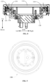
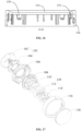
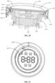
- FIG. 3 A knob assembly and an electrical apparatus provided according to some embodiments of the application are described below with reference to FIG. 1 to FIG. 21 .
- arrows in FIG. 3 , FIG. 5 , FIG. 8 , FIG. 19 and FIG. 20 indicate a flow direction of liquid.
- an embodiment of the application provides a knob assembly, which includes an assembly member 140, a control module 162, a display module 120, a knob base 106, a knob body 116, and a liquid discharging part 126.
- the assembly member 140 is provided with a mounting groove 142, and the control module 162 is arranged in the mounting groove 142, to ensure a stable mounting of the control module 162.
- the display module 120 and the knob body 116 are electrically connected to the control module 162, and the knob body 116 is rotatable relative to the display module 120.
- the knob body 116 When the knob assembly is in use, the knob body 116 may be rotated to select a procedure, and information such as a procedure parameter or running status corresponding to the procedure may be displayed by the display module 120.
- the knob assembly provided by the application is integrated with control and display functions. Therefore, the structure of the knob assembly is novel, the space occupied by the knob assembly is small, the operation of the knob assembly is convenient, and the cost of an electrical apparatus to which the knob assembly is applied may be reduced.
- the knob body 116 and the knob base 106 together define a liquid discharging cavity 122, and the liquid discharging part 126 in communication with the liquid discharging cavity 122 is arranged on the knob base 106.
- the liquid entering an interior of the knob assembly first enters into the liquid discharging cavity 122, and the liquid inside the liquid discharging cavity 122 may be directly discharged through the liquid discharging part 126.
- the liquid is prevented from retaining inside the knob assembly, and the liquid entering the interior of the knob assembly can be discharged in time, which ensures a dry environment inside the knob assembly.
- the liquid entering into the liquid discharging cavity 122 is prevented from flowing to the display module 120 and the control module 162, and the damage of the knob assembly caused by the entry of water or water mist is prevented.
- the assembly member 140 further includes a first liquid blocking part 144, and the first liquid blocking part 144 is located at an outer periphery of the mounting groove 142.
- the first liquid blocking part 144 is located between the knob body 116 and the control module 162, and blocks the liquid between the knob body 116 and the control module 162. Therefore, the external liquid is prevented from entering into the mounting groove 142 and from coming into contact with the control module 162, which ensures a surrounding environment of the control module 162, and prevents the damage of the control module 162 caused by the entry of the liquid.
- the embodiment of the application may avoid the design of a sealing ring in the related art due to the design of the first liquid blocking part 144, which may ensure that there is no direct contact between the knob body 116 and the display module 120, and there is no direct contact between the knob body 116 and the assembly member 140, and which may ensure the smooth rotation of the knob body.
- the assembly member 140 and the display module 120 of the knob assembly serve as a fixing structure of the knob assembly, and the knob body 116 serves as a rotating structure of the knob assembly. Therefore, there is a certain gap between the knob body 116 and the display module 120, and there is a certain gap between the knob body 116 and the assembly member 140, to ensure the smooth and unobstructed rotation of the knob body.
- the knob assembly may be applied to an electrical apparatus such as a washing machine or a laundry dryer.
- a working environment for the electrical apparatus such as the washing machine or the laundry dryer is generally a space with heavy humidity, such as a bathroom. It is easy for the liquid to be dripped onto the display module 120, and it is easy for condensed water to be generated on the knob assembly during the drying of a laundry, which leads to a risk that the water enters the interior of the knob assembly.
- the knob base 106 and the knob body 116 together define the liquid discharging cavity 122, to allow the liquid entering the interior of the knob assembly to enter into the liquid discharging cavity 122 first. Therefore, the liquid entering the interior of the knob assembly is prevented from flowing and spreading in the interior of the knob assembly.
- the liquid discharging part 126 is arranged on the knob base 106, to allow the liquid entering into the liquid discharging cavity 122 to be discharged from the liquid discharging part 126.
- the liquid is prevented from retaining in the liquid discharging cavity 122 for a long time, which ensures the dry environment inside the knob assembly, ensures that the liquid inside the liquid discharging cavity 122 is discharged by the knob assembly in time, and ensures the service life of the knob assembly.
- the first liquid blocking part 144 may be located between the knob body 116 and the mounting groove 142. Therefore, the first liquid blocking part 144 may play a good effect of blocking the liquid for the control module 162 arranged in the mounting groove 142. In this way, on the one hand, the liquid on a surface of the knob body 116 is prevented from entering the mounting groove 142, and on the other hand, the liquid between the knob body 116 and the display module 120 is prevented from entering the mounting groove 142. Therefore, the effective effect of blocking the liquid for the mounting groove 142 is realized, a dry environment inside the mounting groove 142 is ensured, and the service life of the control module 162 is ensured.
- the assembly member 140 includes an assembly surface 160.
- the mounting groove 142 and the first liquid blocking part 144 are arranged on the assembly surface 160
- the control module 162 is assembled inside the mounting groove 142
- the knob body 116 is arranged on a surface of the assembly surface 160.
- there is a certain distance between the knob body 116 and the assembly surface 160 there is no direct contact between the knob body 116 that is rotated and the assembly surface 160 that is fixed, which ensures the smooth rotation of the knob body 116.
- the first liquid blocking part 144 is connected to a side wall of the mounting groove 142, and protrudes from the assembly surface 160. In this way, the first liquid blocking part 144 may effectively block the liquid on a peripheral side of the mounting groove 142, to prevent the external liquid from flowing into the mounting groove 142 from a gap between the assembly surface 160 and the knob body 116.
- the first liquid blocking part 144 is located between the knob body 116 and the mounting groove 142, and the first liquid blocking part 144 is connected to the side wall of the mounting groove 142, which may effectively reduce a distance from the knob body 116 to the mounting groove 142. Therefore, the structure consisting of the knob body 116, the display module 120 and the control module 162 is compact, and the miniaturization design of the knob assembly is realized.
- the knob assembly further includes a second liquid blocking part 128.
- the second liquid blocking part 128 is arranged on the knob base 106 and is located between the first liquid blocking part 144 and the knob body 116.
- an extension direction of the first liquid blocking part 144 is different from an extension direction of the second liquid blocking part 128.
- the first liquid blocking part 144 is arranged on the assembly member 140, and extends towards the knob base 106 located above the first liquid blocking part.
- the second liquid blocking part 128 is arranged on the knob base 106, and extends towards the assembly member 140 located below the second liquid blocking part.
- the first liquid blocking part 144 and the second liquid blocking part 128 with different extending directions are arranged between the knob body 116 and the mounting groove 142.
- Two waterproof structures may be formed by the cooperation of the first liquid blocking part 144 and the second liquid blocking part 128. Therefore, the external liquid is prevented from entering into the mounting groove 142.
- the liquid dripping from the knob body 116 is prevented from entering into the mounting groove 142
- the liquid dripping from the knob body is prevented from entering into the mounting groove 142 from the gap between the knob body 116 and the assembly surface 160.
- the liquid discharging part 126 is a liquid discharging channel, which is defined by the second liquid blocking part 128 and the knob body 116 together.
- the liquid discharging channel has a certain liquid discharging direction and liquid discharging length. Therefore, the liquid discharging direction of the liquid discharging channel may be arranged to allow the liquid to be discharged by the liquid discharging channel in a direction away from the display module 120 and the control module 162, which prevents the liquid discharged from the liquid discharging channel from entering the interior of the knob assembly again.
- the first liquid blocking part 144 and the second liquid blocking part 128 are arranged between the liquid discharging part 126 and the mounting groove 142.
- the first liquid blocking part 144 and the second liquid blocking part 128 may block the liquid between the liquid discharging part 126 and the mounting groove 142. Therefore, the liquid discharged from the liquid discharging part 126 is prevented from entering into the mounting groove 142, which ensures the safety of use of the control module 162 arranged in the mounting groove 142.
- liquid discharging part 126 may also directly be a liquid discharging port, which penetrates through the knob base 106.
- liquid discharging parts 126 are water guide grooves arranged on an outer periphery of the second liquid blocking part 128, and are spaced apart from each other in a circumferential direction of the second liquid blocking part 128.
- An outer wall of the second liquid blocking part 128 is in close contact with an inner wall of the knob body 116, and is only provided with an opening at each of the water guide grooves. In this way, the external liquid does not easily enter into the liquid discharging cavity 122, and the liquid in the liquid discharging cavity 122 may flow out through the liquid discharging parts 126, which satisfactorily achieves the functions of blocking the liquid and discharging the liquid.
- each of the first liquid blocking part 144 and the second liquid blocking part 128 is an annular rib.
- the control module 162 is located in a space defined by the first liquid blocking part 144.
- the first liquid blocking part 144 is located in a space defined by the second liquid blocking part 128.
- the knob body 116 is located at an outer periphery of the second liquid blocking part 128. In this way, there are at least two waterproof structures in a direction from the knob body 116 to the mounting groove 142.
- the knob assembly may be transversely arranged after being mounted to the electrical apparatus. Therefore, the design that each of the first liquid blocking part 144 and the second liquid blocking part 128 is an annular rib may ensure the waterproof effect of the knob assembly in all directions, and may realize the all-round waterproofness of the knob assembly.
- the knob assembly may be transversely arranged when it is mounted to an electrical apparatus for use. Therefore, the first liquid blocking part 144 and the second liquid blocking part 128 are designed to allow the liquid to be well blocked by the knob assembly in a case of the knob assembly with a transverse arrangement, which in turn ensures the safety of use of the control module 162 arranged in the mounting groove 142.
- the first liquid blocking part 144 and the second liquid blocking part 128 are configured to block the liquid between the liquid discharging part 126 and the mounting groove 142.
- Each of the first liquid blocking part 144 and the second liquid blocking part 128 is arranged between the liquid discharging part 126 and the mounting groove 142, to enable the first liquid blocking part 144 and the second liquid blocking part 128 to block the liquid between the liquid discharging part 126 and the mounting groove 142. Therefore, the liquid discharged from the liquid discharging part 126 is prevented from entering into the mounting groove 142, which ensures the safety of use of the control module 162 arranged in the mounting groove 142.
- the liquid entering the interior of the knob assembly first enters into the liquid discharging cavity 122, and the liquid inside the liquid discharging cavity 122 may be directly discharged through the liquid discharging part 126.
- the liquid is prevented from retaining inside the knob assembly, and the liquid entering the interior of the knob assembly can be discharged in time, which ensures a dry environment inside the knob assembly.
- the liquid entering into the liquid discharging cavity 122 is prevented from flowing to the display module 120 and the control module 162, and the damage of the knob assembly caused by the entry of water or water mist is prevented.
- the distance from the knob body 116 to the assembly surface 160 is less than a height of the first liquid blocking part 144 by which the first liquid blocking part 144 protrudes from the assembly surface 160. That is, in a height direction of the knob assembly, a part of the first liquid blocking part 144 overlaps with a part of the knob body 116.
- an internal space of the knob assembly may be completely obscured by the cooperation of the first liquid blocking part 144 and the second liquid blocking part 128 when viewed from a lateral side of the knob assembly, to force the liquid dripping from the knob body 116 to directly fall onto an outer periphery of the first liquid blocking part 144, and in turn prevent the liquid dripping from the knob body from flowing into the mounting groove 142 under the blocking of the first liquid blocking part 144.
- the knob assembly may be transversely arranged when it is in use.
- an internal structure of the knob assembly may be completely obscured by the cooperation of the first liquid blocking part 144 and the second liquid blocking part 128, to enable the first liquid blocking part 144 and the second liquid blocking part 128 to still play a good effect of blocking the liquid when the knob assembly is transversely arranged. Therefore, the external liquid is prevented from entering into the mounting groove 142, and the working environment and the service life of the knob assembly are ensured.
- the knob assembly further includes a third liquid blocking part 130.
- the third liquid blocking part 130 is arranged on the knob base 106.
- an extension direction of the third liquid blocking part 130 is different from an extension direction of the second liquid blocking part 128.
- the second liquid blocking part 128 extends downward from the knob base 106
- the third liquid blocking part 130 extends upward from the knob base 106
- the third liquid blocking part 130 is located between the display module 120 and the knob body 116. In this way, the third liquid blocking part 130 may block the liquid between the knob body 116 and the display module 120.
- the knob body 116 serves as a rotating structure of the knob assembly
- the display module 120 serves as a fixing structure of the knob assembly. Therefore, there is a certain gap between the knob body and the display module, to ensure the smooth rotation of the knob body 116.
- the liquid may enter into the gap. Therefore, the third liquid blocking part 130 is arranged between the display module 120 and the knob body 116, and is configured to block said liquid from entering a position where the display module 120 is located, to ensure the environment of the display module 120 and the service life of the display module 120.
- the knob assembly further includes a lid plate 118 and a fourth liquid blocking part 132.
- the lid plate 118 is capped on the display module 120, to enable the lid plate to play a certain role of protecting the display module 120. Therefore, on the one hand, the display module 120 is prevented from being bumped, and on the other hand, the water is prevented from entering the display module 120.
- the lid plate 118 may be decorated with patterns or colors, to ensure a final presentation state of the light emitted from the display module 120.
- the fourth liquid blocking part 132 is arranged at a peripheral edge of the lid plate 118, and is located between the third liquid blocking part 130 and the knob body 116.
- an extension direction of the fourth liquid blocking part 132 is different from an extension direction of the third liquid blocking part 130.
- the third liquid blocking part 130 is arranged on the knob base 106 and extends upward from the knob base
- the fourth liquid blocking part 132 is arranged on the lid plate 118 and extends downward from the lid plate.
- two waterproof structures may be formed between the knob body 116 and the display module 120 by the cooperation of the third liquid blocking part 130 and the fourth liquid blocking part 132, to further improve the waterproof effect of the display module 120 and realize all-round waterproofness of the display module.
- the fourth liquid blocking part 132 is arranged at a peripheral edge of the lid plate 118.
- a gap 124 is formed between the fourth liquid blocking part 132 and the knob body 116.
- the gap 124 ensures that there is no direct contact between the knob body 116 and the lid plate 118, and that there is no friction between the knob body 116 and the lid plate 118 when the knob body 116 is rotated.
- the gap 124 is in communication with the liquid discharging cavity 122. In this way, the liquid flowing into the gap 124 may directly enter into the liquid discharging cavity 122 when the knob assembly is in use. Therefore, the liquid flowing into the gap does not flow and spread everywhere, and is finally discharged through the liquid discharging part 126, to ensure the working environment and the service life of the display module 120 and of other control module 162.
- the assembly member 140 and the display module 120 of the knob assembly serve as the fixing structure of the knob assembly
- the knob body 116 serves as the rotating structure of the knob assembly.
- the gap 124, the liquid discharging cavity 122 and the liquid discharging part 126 constitute a flow channel.
- the flow channel is formed between the fixing structure and the rotating structure of the knob assembly, isolated from the display module 120 and the control module 162 of the knob assembly, and located on an outer periphery of the display module 120 and an outer periphery of the control module 162.
- the fourth liquid blocking part 132 extends toward an inner side of the liquid discharging cavity 122, and is located inside the liquid discharging cavity 122. In this way, the liquid entering the gap 124 formed between the lid plate 118 and the knob body 116 spreads along the fourth liquid blocking part 132, and drips into the liquid discharging cavity 122 from an end of the fourth liquid blocking part 132. Therefore, the liquid entering the gap 124 formed between the lid plate 118 and the knob body 116 is prevented from spreading to the position where the display module 120 is located.
- the gap 124 is formed between the fourth liquid blocking part 132 and the knob body 116.
- each of the third liquid blocking part 130 and the fourth liquid blocking part 132 is located between the liquid discharging cavity 122 and the display module 120, and the third liquid blocking part 130 and the fourth liquid blocking part 132 are configured to block the liquid between the liquid discharging cavity 122 and the display module 120, and to further block the liquid entering into the liquid discharging cavity 122 from flowing to the display module 120. Therefore, the service life of the display module 120 is ensured.
- each of the third liquid blocking part 130 and the fourth liquid blocking part 132 is an annular rib.
- the display module 120 is located in a space defined by the third liquid blocking part 130.
- the third liquid blocking part 130 is located in a space defined by the fourth liquid blocking part 132.
- the knob body 116 is located at an outer periphery of the fourth liquid blocking part 132.
- the knob assembly may be transversely arranged after being mounted to the electrical apparatus. Therefore, the design that each of the third liquid blocking part 130 and the fourth liquid blocking part 132 is an annular rib may ensure the waterproof effect of the knob assembly in all directions, and may realize the all-round waterproofness of the knob assembly.
- a distance from the fourth liquid blocking part 132 to the knob base 106 is less than a height of the third liquid blocking part 130 by which the third liquid blocking part 130 protrudes from the knob base 106. That is, in the height direction of the knob assembly, a part of the third liquid blocking part 130 overlaps with a part of the fourth liquid blocking part 132. In this way, when viewed from the lateral side of the knob assembly, the display module 120 is completely isolated, which effectively ensures the waterproof effect of the display module 120.
- the knob assembly may be transversely arranged when it is in use.
- the display module 120 may be completely obscured by the cooperation of the third liquid blocking part 130 and the fourth liquid blocking part 132, to enable the third liquid blocking part 130 and the fourth liquid blocking part 132 to still play a good effect of blocking the liquid when the knob assembly is transversely arranged. Therefore, the external liquid is prevented from entering the position where the display module 120 is located, and the working environment and the service life of the display module 120 are ensured.
- the knob assembly further includes a module support 108.
- the module support 108 is arranged on the control module 162, and the display module 120 is arranged on the module support 108, to ensure the stable mounting of the display module 120.
- the fourth liquid blocking part 132 is provided with a first snap 148, and a lid body of the lid plate may be mounted on the module support 108 by the first snap 148, to ensure the stable connection of the lid body.
- the first snap 148 is arranged to enable the fourth liquid blocking part 132 to have the functions of blocking the liquid and mounting the lid body. Therefore, the separate design of a drainage structure, a liquid blocking structure and a mounting structure is avoided, the overall structure of the knob assembly is simplified, and the miniaturization design of the knob assembly is realized.
- the module support 108 is provided with a flange 146.
- the flange 146 is capped above the third liquid blocking part 130, and is at least located between the third liquid blocking part 130 and the knob body 116.
- the cooperation of the flange 146 and the third liquid blocking part 130 may further improve the waterproof effect of the knob assembly, in particular to prevent the external liquid from flowing to the display module 120 through the third liquid blocking part 130.
- the first snap 148 is connected to the flange 146, to enable the flange 146 to have the functions of mounting the lid plate 118 and blocking the liquid.
- the knob body 116 is provided with a second snap 150, to allow the knob body 116 to be mounted on the knob base 106 by the second snap 150, to ensure the stable mounting of the knob body 116.
- the user may rotate a rotating part 134 of an encoder 104 by the knob body 116 and the knob base 106, and then select a corresponding procedure.
- the third liquid blocking part 130 has the functions of blocking the liquid and mounting the knob body 116.
- the knob base 106 is an annular base, and is located at an outer periphery of the module support 108 and an outer periphery of the display module 120.
- the liquid discharging cavity 122 is an annular cavity, and is located at the outer periphery of the module support 108 and the outer periphery of the display module 120.
- the knob assembly further includes a main control panel 102, an encoder 104 and a lead 138.
- the lead 138 is electrically connected to the main control panel 102 and the display module 120.
- the main control panel 102 is arranged in the mounting groove 142
- the encoder 104 is arranged on the main control panel 102 and electrically connected to the main control panel 102.
- the encoder 104 includes a rotating part 134 and a fixing part 136.
- the knob base is arranged on the rotating part 134, and the knob body 116 is arranged on the knob base 106, to ensure the rotation of the knob body 116.
- the module support 108 is arranged on the fixing part 136, and the display module 120 is arranged on the module support 108, to ensure the fixed connection of the display module 120.
- the lead 138 is connected to the main control panel 102 and the display module 120, to ensure the signal transmission between the main control panel 102 and the display module 120. Therefore, the display module 120 may display the parameter information corresponding to the signal.
- a display support 112 is arranged on the module support 108.
- a display panel 110 is arranged on a side of the display support 112 facing toward the module support 108.
- the display panel 110 is electrically connected to the main control panel 102 by the lead 138.
- a display film 114 is arranged on a side of the display support 112 away from the module support 108.
- the display support 112 is provided with a light guide hole, and the display film 114 is provided with characters or patterns.
- the embodiment of the application provides an electrical apparatus, which includes the knob assembly according to any one of the above embodiments.
- the electrical apparatus provided by the embodiment of the present application includes the knob assembly according to any one of the above embodiments. Therefore, all the beneficial effects based on the above electrical apparatus will not be discussed one by one herein.
- the electrical apparatus includes, but is not limited to, a washing machine, a laundry dryer, a laundry washer-dryer, and the like.
- the knob assembly includes an assembly member 140, a main control panel 102, an encoder 104, a module support 108, a display module 120, a knob base 106, a knob body 116, a lid plate 118, and the like.
- the assembly member 140 is provided with a mounting groove 142, and the main control panel 102 and the encoder 104 are arranged in the mounting groove 142.
- the encoder 104 includes a rotating part 134 and a fixing part 136.
- the module support 108 is connected to the fixing part 136 of the encoder 104, and the display module 120 is arranged on the module support 108.
- the lid plate 118 is capped on the display module 120, and is connected to the module support 108.
- the knob base 106 is connected to the rotating part 134 of the encoder 104.
- the knob body 116 is arranged on the knob base 106, and is located outside the display module 120.
- the knob body 116 and the knob base 106 define a liquid discharging cavity 122.
- a gap 124 is formed between a peripheral edge of the lid plate 118 and the knob body 116.
- a liquid discharging part 126 is formed between the knob base and the knob body 116.
- Each of the gap 124 and the liquid discharging part 126 is in communication with a respective one of two opposite sides of the liquid discharging cavity 122 (specifically, the gap 124 is in communication with a side of the two opposite sides which is located above the liquid discharging cavity 122, and the liquid discharging part 126 is in communication with another side of the two opposite sides which is located below the liquid discharging cavity 122).
- the gap 124, the liquid discharging cavity 122 and the liquid discharging part 126 constitute a flow channel.
- the flow channel is formed between a fixing structure and a rotating structure of the knob assembly, isolated from the display module 120 and the control module 162 of the knob assembly, and located on an outer periphery of the display module 120 and an outer periphery of the control module 162.
- the design of the flow channel on the one hand ensures the smooth rotation of the knob body 116, and on the other hand, ensures the effect of discharging the liquid of the knob assembly.
- the above effect may be realized without additional complex structures, which facilitates processing and manufacturing, and is also beneficial for realization of the most simplified design of the knob assembly.
- an assembly surface 160 of the assembly member 140 is provided with a first liquid blocking part 144.
- the first liquid blocking part 144 is located between the knob body 116 and the control module 162, and is configured to block the liquid between the knob body 116 and the control module 162. Therefore, the external liquid is prevented from entering into the mounting groove 142, which ensures the surrounding environment of the control module 162, and prevents the damage of the control module 162 caused by the entry of the liquid.
- the knob base 106 extends toward a peripheral side, and is capped on the first liquid blocking part 144.
- An edge of the knob base 106 is provided with a second liquid blocking part 128, the knob body 116 is located at an outer periphery of the second liquid blocking part 128, and the liquid discharging part 126 is formed between the second liquid blocking part 128 and the knob body 116.
- each of the first liquid blocking part 144 and the second liquid blocking part 128 is arranged between the liquid discharging part 126 and the mounting groove 142, to allow the first liquid blocking part 144 and the second liquid blocking part 128 to simultaneously exist between the liquid discharging part 126 and the mounting groove 142.
- Two waterproof structures may be formed by the cooperation of the first liquid blocking part 144 and the second liquid blocking part 128, to prevent the liquid discharged from the liquid draining portion 126 and the external liquid from entering into the mounting groove 142, which ensures the safety of use of the control module 162 arranged in the mounting groove 142.
- the knob base 106 is provided with a third liquid blocking part 130.
- the third liquid blocking part 130 extends upward from the knob base 106, and is located between the display module 120 and the knob body 116.
- the third liquid blocking part 130 may block the liquid between the knob body 116 and the display module 120, and in particular may block the liquid inside the liquid discharging cavity 122 from entering a position where the display module 120 is located, to ensure the environment of the display module 120 and the service life of the display module 120.
- a peripheral edge of the lid plate 118 is provided with a fourth liquid blocking part 132.
- the gap 124 is formed between the fourth liquid blocking part 132 and the knob body 116, and the fourth liquid blocking part 132 is located between the third liquid blocking part 130 and the gap 124.
- two waterproof structures may be formed between the gap 124 and the display module 120 by the cooperation of the third liquid blocking part 130 and the fourth liquid blocking part 132, to further improve the waterproof effect of the display module 120, realize the all-round waterproofness of the display module, and ensure the service life of the display module 120.
- the fourth liquid blocking part 132 extends from the gap 124 toward an interior of the liquid discharging cavity 122, to enable the fourth liquid blocking part 132 to serve as a drainage rib.
- the liquid entering the gap 124 formed between the lid plate 118 and the knob body 116 spreads along the fourth liquid blocking part 132, and drips into the liquid discharging cavity 122 from an end of the fourth liquid blocking part 132. Therefore, the liquid entering the gap 124 formed between the lid plate 118 and the knob body 116 is prevented from spreading to the position where the display module 120 is located.
- a control panel of most washing machines in a market generally has three areas: a display area, a button and a knob. Due to the increasing functions of the washing machine, the operation methods of the washing machines become increasingly diversified and complex. Most knobs are ordinary plastic knobs, which are intended to select a procedure and have a single function and appearance. With the improvement of quality of life and aesthetic requirements by people, there is a need for the knobs to improve their functionality, simplify their operation, and have breakthrough appearances.
- the embodiment of the application designs a knob assembly, which is integrated with a display function and a procedure selection function.
- the appearance of the knob assembly is novel, and the operation of the knob assembly is simple.
- the knob assembly includes an encoding switch and a lid plate 118.
- the encoding switch includes a rotating portion (the knob base 106, the knob body 116 and a knob decorative member 156), the encoder 104 and its main control panel 102, and a fixing display portion (the display module 120, the module support 108 and the lid plate 118).
- the display module 120 includes a display panel 110, a display support 112, and a display film 114.
- the encoder 104 acts as an intermediary to associate the rotating portion with the fixing display portion.
- the encoder 104 is mounted on the main control panel 102, and the encoder and the main control panel are welded together by stitch welding.
- the rotation of the encoder 104 triggers the procedure of the main control panel 102.
- the knob base 106 is fixed to the rotating part 134 of the encoder 104 by a fifth snap 158 distributed in a circumferential direction of the knob base 106.
- the knob body 116 is fixed to the knob base 106 by a second snap 150 of the knob body which is located on inner side of the knob body.
- the knob decorative member 156 functions to indicate the procedure, and is fixed to the knob body 116 by a third snap 152.
- the module support 108 is fixed to the fixing part 136 of the encoder 104 by a fourth snap 154 distributed in a circumferential direction of the module support. The entire portion of the module support is stationary. In this way, the display portion is stationary when the knob body 116 is rotated.
- the display module 120 is arranged on the module support 108.
- the display panel 110 is mounted on a back surface of the display support 112, and is fixed to the back surface of the display support 112 by sealing glue.
- the display film 114 is adhered to a front surface of the display support 112.
- the display film 114 is printed with characters or patterns to be displayed.
- the light emitting diode of the display panel 110 is illuminated, and is displayed through the display support 112 and the display film 114.
- the lid plate 118 is capped on the display module 120, and is mounted on the module support 108 by the first snap 148.
- the first snap 148 is arranged on the fourth liquid blocking part 132, to enable the fourth liquid blocking part 132 to have the functions of drainage, liquid blocking, and mounting and fixing.
- the lid plate 118 is generally decorated with patterns or colors. The state in which the light emitted from the display module 120 is finally presented on the knob assembly is ensured.
- the embodiments of the application improve the water discharging property and water blocking property of the knob assembly.
- water flow may enter the interior of the knob assembly through the gap 124 between the lid plate 118 arranged on a front of the knob assembly and the knob body 116, or through the gap 124 between the assembly member 140 and the knob body 116.
- the fourth liquid blocking part 132 is arranged at an edge of the lid plate 118, and the third liquid blocking part 130 cooperating with the fourth liquid blocking part 132 is arranged on the knob base 106, to reduce a possibility that water flow enters the interior of the knob assembly from a front surface of the knob assembly.
- multiple liquid discharging parts 126 are distributed around the knob base 106, to guide water flow to flow out of the multiple liquid discharging parts 126.
- the second liquid blocking part 128 arranged on the knob base 106 and the first liquid blocking part 144 arranged on the assembly member 140 also block the water flow originating from an external side surface of the knob assembly from entering the interior of the knob assembly.
- the knob assembly realizes the effect of integrating the procedure selection function and the display function, thus the display area of the electrical apparatus to which the knob assembly is applied is reduced, and the original display area has more design space.
- the waterproofness and drainage property of the knob assembly are effectively ensured by improving the internal structure of the knob assembly (the first liquid blocking part 144, the second liquid blocking part 128, the third liquid blocking part 130, the fourth liquid blocking part 132 and the liquid discharging part 126).
- connection means a fixed connection, a detachable connection, or an integral connection, and “connected” may be directly connected, or indirectly connected through an intermediary.
- connection may be a fixed connection, a detachable connection, or an integral connection, and “connected” may be directly connected, or indirectly connected through an intermediary.
- the description of the terms “one embodiment”, “some embodiments”, “specific embodiments”, and the like means that specific features, structures, materials, or characteristics described in combination with the embodiment or example are included in at least one embodiment or example of the application.
- the schematic expressions of the above terms do not necessarily refer to the same embodiments or examples.
- the specific features, the structures, the materials, or the characteristics described may be combined in any one or more embodiments or examples in a suitable manner.
Landscapes
- Engineering & Computer Science (AREA)
- Textile Engineering (AREA)
- Computer Networks & Wireless Communication (AREA)
- Rotary Switch, Piano Key Switch, And Lever Switch (AREA)
- Casings For Electric Apparatus (AREA)
Claims (14)
- Knopfbaugruppe, umfassend: ein Baugruppenelement (140), das eine Montagerille (142) und einen ersten Flüssigkeitssperrteil (144) umfasst, wobei sich der erste Flüssigkeitssperrteil (144) an einem Außenumfang der Montagerille (142) befindet; ein Steuermodul (162), das in der Montagerille (142) angeordnet ist; ein Anzeigemodul (120), das elektrisch mit dem Steuermodul (162) verbunden ist; einen Knopfsockel (106), der mit dem Steuermodul (162) verbunden ist; einen Knopfhauptteil (116), der auf dem Knopfsockel (106) angeordnet ist und sich an einem Außenumfang des Steuermoduls (162) befindet, wobei der Knopfhauptteil (116) und der Knopfsockel (106) einen Flüssigkeitsablass-Hohlraum (122) definieren; und einen Flüssigkeitsablassteil (126), der an dem Knopfsockel (106) angeordnet ist, wobei der Flüssigkeitsablassteil (126) in Verbindung mit dem Flüssigkeitsablass-Hohlraum (122) steht und dafür gestaltet ist, ein Medium in dem Flüssigkeitsablass-Hohlraum (122) abzulassen, wobei sich der erste Flüssigkeitssperrteil (144) zwischen dem Flüssigkeitsablassteil (126) und der Montagerille (142) befindet, ferner Folgendes umfassend:
einen zweiten Flüssigkeitssperrteil (128), der an dem Knopfsockel (106) angeordnet ist und sich zwischen dem ersten Flüssigkeitssperrteil (144) und dem Flüssigkeitsablassteil (126) befindet. - Knopfbaugruppe nach Anspruch 1, wobei das Baugruppenelement (140) eine Baugruppenoberfläche (160) umfasst und die Montagerille (142) auf der Baugruppenoberfläche (160) angeordnet ist, wobei der erste Flüssigkeitssperrteil (144) mit einer Seitenwand der Montagerille (142) verbunden ist und aus der Baugruppenoberfläche (160) hervorsteht.
- Knopfbaugruppe nach Anspruch 1, wobei der Flüssigkeitsablassteil (126) ein Flüssigkeitsablasskanal ist, der zwischen dem zweiten Flüssigkeitssperrteil (128) und dem Knopfhauptteil (116) gebildet ist.
- Knopfbaugruppe nach Anspruch 1, wobei der erste Flüssigkeitssperrteil (144) eine ringförmige Rippe ist und der zweite Flüssigkeitssperrteil (128) eine ringförmige Rippe ist, sich das Steuermodul (162) in einem Raum befindet, der durch den ersten Flüssigkeitssperrteil (144) definiert ist, sich der erste Flüssigkeitssperrteil (144) in einem Raum befindet, der durch den zweiten Flüssigkeitssperrteil (128) definiert ist, sich der Knopfhauptteil (116) an einem Außenumfang des zweiten Flüssigkeitssperrteils (128) befindet.
- Knopfbaugruppe nach einem der Ansprüche 1 bis 4, ferner Folgendes umfassend: einen dritten Flüssigkeitssperrteil (130), der am Knopfsockel (106) angeordnet ist und sich zwischen dem Anzeigemodul (120) und dem Flüssigkeitsablass-Hohlraum (122) befindet.
- Knopfbaugruppe nach Anspruch 5, ferner Folgendes umfassend: eine Deckelplatte (118), die auf das Anzeigemodul (120) aufgesetzt ist, wobei die Deckelplatte (118) den dritten Flüssigkeitssperrteil (130) abdeckt, und einen vierten Flüssigkeitssperrteil (132), der auf der Deckelplatte (118) angeordnet ist und sich zwischen dem dritten Flüssigkeitssperrteil (130) und dem Flüssigkeitsablass-Hohlraum (122) befindet.
- Knopfbaugruppe nach Anspruch 6, wobei der vierte Flüssigkeitssperrteil (132) an einem Umfangsrand der Deckelplatte (118) angeordnet ist und sich hin zu einer Innenseite des Flüssigkeitsablass-Hohlraums (122) erstreckt, ein Spalt (124) zwischen dem vierten Flüssigkeitssperrteil (132) und dem Knopfhauptteil (116) gebildet ist und der Spalt (124) in Verbindung mit dem Flüssigkeitsablass-Hohlraum (122) steht.
- Knopfbaugruppe nach Anspruch 7, wobei der dritte Flüssigkeitssperrteil (130) eine ringförmige Rippe ist und der vierte Flüssigkeitssperrteil (132) eine ringförmige Rippe ist, sich das Anzeigemodul (120) in einem Raum befindet, der durch den dritten Flüssigkeitssperrteil (130) definiert ist, sich der dritte Flüssigkeitssperrteil (130) in einem Raum befindet, der durch den vierten Flüssigkeitssperrteil (132) definiert ist, sich der Knopfhauptteil (116) an einem Außenumfang des vierten Flüssigkeitssperrteils (132) befindet.
- Knopfbaugruppe nach Anspruch 6, ferner Folgendes umfassend: einen Modulträger (108), der mit dem Anzeigemodul (120) und dem Steuermodul (162) verbunden ist, wobei der vierte Flüssigkeitssperrteil (132) mit einem ersten Schnapper (148) versehen ist und der erste Schnapper mit dem Modulträger (108) verbunden ist.
- Knopfbaugruppe nach Anspruch 9, wobei der Modulträger (108) mit einem Flansch (146) versehen ist, der Flansch (146) auf den dritten Flüssigkeitssperrteil (130) aufgesetzt ist und der erste Schnapper (148) mit dem Flansch (146) verbunden ist.
- Knopfbaugruppe nach Anspruch 5, wobei der Knopfhauptteil (116) mit einem zweiten Schnapper (150) versehen ist und der zweite Schnapper (150) mit dem Knopfsockel (106) verbunden ist.
- Knopfbaugruppe nach Anspruch 9, wobei der Knopfsockel (106) ein ringförmiger Sockel ist und sich an einem Außenumfang des Modulträgers (108) befindet und/oder der Flüssigkeitsablass-Hohlraum (122) ein ringförmiger Hohlraum ist und sich an einem Außenumfang des Modulträgers (108) befindet.
- Knopfbaugruppe nach Anspruch 9, wobei das Steuermodul (162) Folgendes umfasst: eine Hauptsteuertafel (102), die in der Montagerille (142) angeordnet ist; einen Codierer (104), der mit der Hauptsteuertafel (102) verbunden ist, wobei der Codierer (104) einen drehenden Teil (134) und einen Befestigungsteil (136) umfasst, der Knopfsockel (106) an dem drehenden Teil (134) angeordnet ist, der Modulträger (108) an dem Befestigungsteil (136) angeordnet ist; und eine Leitung (138), die elektrisch mit der Hauptsteuertafel (102) und dem Anzeigemodul (120) verbunden ist, wobei das Anzeigemodul (120) optional Folgendes umfasst: einen Anzeigeträger (112), der an dem Modulträger (108) angeordnet ist; eine Anzeigetafel (110), die an einer Seite des Anzeigeträgers (112) angeordnet ist, die hin zum Modulträger (108) weist, wobei die Anzeigetafel (110) elektrisch mit der Hauptsteuertafel (102) verbunden ist; und eine Anzeigefolie (114), die an einer Seite des Anzeigeträgers (112) angeordnet ist, die von dem Modulträger (108) abgewandt ist, wobei der Anzeigeträger (112) mit einer Lichtleiteröffnung versehen ist und die Anzeigefolie (114) mit Zeichen oder Mustern versehen ist.
- Elektrische Vorrichtung, Folgendes umfassend: die Knopfbaugruppe nach einem der Ansprüche 1 bis 13.
Applications Claiming Priority (2)
| Application Number | Priority Date | Filing Date | Title |
|---|---|---|---|
| CN202011595610.2A CN112538723B (zh) | 2020-12-29 | 2020-12-29 | 旋钮组件和电器设备 |
| PCT/CN2021/082525 WO2022141830A1 (zh) | 2020-12-29 | 2021-03-24 | 旋钮组件和电器设备 |
Publications (3)
| Publication Number | Publication Date |
|---|---|
| EP4249665A1 EP4249665A1 (de) | 2023-09-27 |
| EP4249665A4 EP4249665A4 (de) | 2024-01-17 |
| EP4249665B1 true EP4249665B1 (de) | 2025-01-29 |
Family
ID=75017808
Family Applications (1)
| Application Number | Title | Priority Date | Filing Date |
|---|---|---|---|
| EP21912600.0A Active EP4249665B1 (de) | 2020-12-29 | 2021-03-24 | Drehknopfbaugruppe und elektrisches gerät |
Country Status (3)
| Country | Link |
|---|---|
| EP (1) | EP4249665B1 (de) |
| CN (1) | CN112538723B (de) |
| WO (1) | WO2022141830A1 (de) |
Families Citing this family (4)
| Publication number | Priority date | Publication date | Assignee | Title |
|---|---|---|---|---|
| CN112538723B (zh) * | 2020-12-29 | 2022-03-25 | 无锡小天鹅电器有限公司 | 旋钮组件和电器设备 |
| KR20230001238A (ko) * | 2021-06-28 | 2023-01-04 | 엘지전자 주식회사 | 인터페이스 및 인터페이스가 구비된 의류처리장치 |
| KR102758941B1 (ko) * | 2021-06-28 | 2025-01-23 | 엘지전자 주식회사 | 인터페이스 및 인터페이스가 구비된 의류처리장치 |
| CN220724587U (zh) * | 2023-08-29 | 2024-04-05 | 无锡美芝电器有限公司 | 一种旋钮组件及衣物处理设备 |
Family Cites Families (24)
| Publication number | Priority date | Publication date | Assignee | Title |
|---|---|---|---|---|
| JPH0724184A (ja) * | 1993-07-05 | 1995-01-27 | Sanyo Electric Co Ltd | 操作パネル装置 |
| JPH08323094A (ja) * | 1995-05-31 | 1996-12-10 | Matsushita Electric Ind Co Ltd | 洗濯機 |
| JP4777070B2 (ja) * | 2006-01-11 | 2011-09-21 | 株式会社東芝 | 洗濯機 |
| KR101395117B1 (ko) * | 2007-03-29 | 2014-05-16 | 삼성전자주식회사 | 세탁기 |
| JP5938553B2 (ja) * | 2012-01-13 | 2016-06-22 | パナソニックIpマネジメント株式会社 | 洗濯機 |
| CN203159948U (zh) * | 2013-02-21 | 2013-08-28 | 松下家电研究开发(杭州)有限公司 | 一种防水型控制面板及洗衣机 |
| CN106350964B (zh) * | 2015-07-21 | 2020-06-16 | 青岛海尔滚筒洗衣机有限公司 | 一种旋钮组件及洗衣机 |
| CN205874773U (zh) * | 2016-06-14 | 2017-01-11 | 松下家电研究开发(杭州)有限公司 | 一种旋钮组件及洗衣机 |
| CN205907514U (zh) * | 2016-06-30 | 2017-01-25 | 合肥美的洗衣机有限公司 | 用于洗衣机的控制面板组件及具有其的洗衣机 |
| CN106012429B (zh) * | 2016-06-30 | 2019-07-19 | 合肥美的洗衣机有限公司 | 用于洗衣机的控制面板组件及具有其的洗衣机 |
| EP3516103B1 (de) * | 2016-09-20 | 2020-06-10 | Arçelik Anonim Sirketi | Haushaltsgerät mit einem knopf |
| CN108691150A (zh) * | 2017-04-12 | 2018-10-23 | 青岛海尔洗衣机有限公司 | 洗衣机的旋钮组件及洗衣机 |
| CN106968085B (zh) * | 2017-04-28 | 2021-09-14 | 青岛海尔洗涤电器有限公司 | 一种洗衣机的旋钮组件、装配方法以及洗衣机 |
| CN107856498A (zh) * | 2017-11-03 | 2018-03-30 | 延锋伟世通电子科技(上海)有限公司 | 一种汽车空调控制器面板机构 |
| CN107675437B (zh) * | 2017-11-14 | 2023-08-01 | 金羚电器有限公司 | 集旋转、触控及显示功能于一体的旋钮及其洗衣机 |
| CN109375702A (zh) * | 2018-10-26 | 2019-02-22 | 青岛海尔滚筒洗衣机有限公司 | 家用电器的控制面板组件 |
| CN210128379U (zh) * | 2019-03-25 | 2020-03-06 | 九阳股份有限公司 | 一种烹饪器具 |
| CN110578234B (zh) * | 2019-06-28 | 2023-09-12 | 重庆海尔滚筒洗衣机有限公司 | 滚筒洗衣机及其控制面板 |
| CN210287837U (zh) * | 2019-06-28 | 2020-04-10 | 无锡小天鹅电器有限公司 | 旋钮组件及衣物处理装置 |
| CN210765983U (zh) * | 2019-09-03 | 2020-06-16 | 珠海格力电器股份有限公司 | 旋钮组件、控制面板以及具有其的洗衣机 |
| CN110485121B (zh) * | 2019-09-03 | 2024-09-10 | 珠海格力电器股份有限公司 | 旋钮组件、控制面板以及具有其的洗衣机 |
| CN112538723B (zh) * | 2020-12-29 | 2022-03-25 | 无锡小天鹅电器有限公司 | 旋钮组件和电器设备 |
| CN112538721B (zh) * | 2020-12-29 | 2022-03-04 | 无锡小天鹅电器有限公司 | 旋钮组件和电器设备 |
| CN112538722B (zh) * | 2020-12-29 | 2022-03-04 | 无锡小天鹅电器有限公司 | 旋钮组件和电器设备 |
-
2020
- 2020-12-29 CN CN202011595610.2A patent/CN112538723B/zh active Active
-
2021
- 2021-03-24 EP EP21912600.0A patent/EP4249665B1/de active Active
- 2021-03-24 WO PCT/CN2021/082525 patent/WO2022141830A1/zh not_active Ceased
Also Published As
| Publication number | Publication date |
|---|---|
| EP4249665A1 (de) | 2023-09-27 |
| CN112538723A (zh) | 2021-03-23 |
| CN112538723B (zh) | 2022-03-25 |
| WO2022141830A1 (zh) | 2022-07-07 |
| EP4249665A4 (de) | 2024-01-17 |
Similar Documents
| Publication | Publication Date | Title |
|---|---|---|
| EP4249665A1 (de) | Drehknopfbaugruppe und elektrisches gerät | |
| KR101203550B1 (ko) | 컨트롤 패널 어셈블리 | |
| CA2473769A1 (en) | An appliance door or lid | |
| JP5625385B2 (ja) | 誘導加熱調理器 | |
| EP4064944B1 (de) | Kochgerät | |
| CN209741487U (zh) | 一种衣物处理装置 | |
| CN112538722B (zh) | 旋钮组件和电器设备 | |
| CN112538721B (zh) | 旋钮组件和电器设备 | |
| WO2022218055A1 (zh) | 一种洗衣机上盖及洗衣机 | |
| CN213988695U (zh) | 一种电磁炉的旋钮防水结构 | |
| CN206006870U (zh) | 一种烹饪器具 | |
| CN212165616U (zh) | 装饰片、控制装置组件和烹饪器具 | |
| CN110195326B (zh) | 一种洗衣机 | |
| CN110578240B (zh) | 一种洗衣机的上盖及洗衣机 | |
| JP3571663B2 (ja) | 電気ポットの操作基板の取り付け方法と、取り付け構造、およびこれらを利用した電気ポット | |
| CN211795838U (zh) | 烹饪设备 | |
| CN210128379U (zh) | 一种烹饪器具 | |
| CN109559922B (zh) | 一种防水开关结构 | |
| CN213849163U (zh) | 一种安装可靠的电饭盒 | |
| CN217408502U (zh) | 一种煲体和烹饪器具 | |
| CN218683806U (zh) | 一种烹饪设备及密封结构 | |
| CN206252405U (zh) | 烹饪器具 | |
| CN208435329U (zh) | 一种显示屏安装结构以及家用电器 | |
| CN217788255U (zh) | 一种电磁烹饪器具 | |
| CN110195334B (zh) | 一种洗衣机盘座及洗衣机 |
Legal Events
| Date | Code | Title | Description |
|---|---|---|---|
| STAA | Information on the status of an ep patent application or granted ep patent |
Free format text: STATUS: THE INTERNATIONAL PUBLICATION HAS BEEN MADE |
|
| PUAI | Public reference made under article 153(3) epc to a published international application that has entered the european phase |
Free format text: ORIGINAL CODE: 0009012 |
|
| STAA | Information on the status of an ep patent application or granted ep patent |
Free format text: STATUS: REQUEST FOR EXAMINATION WAS MADE |
|
| 17P | Request for examination filed |
Effective date: 20230623 |
|
| AK | Designated contracting states |
Kind code of ref document: A1 Designated state(s): AL AT BE BG CH CY CZ DE DK EE ES FI FR GB GR HR HU IE IS IT LI LT LU LV MC MK MT NL NO PL PT RO RS SE SI SK SM TR |
|
| REG | Reference to a national code |
Ref country code: DE Ref legal event code: R079 Free format text: PREVIOUS MAIN CLASS: D06F0039000000 Ipc: D06F0034300000 Ref document number: 602021025710 Country of ref document: DE |
|
| A4 | Supplementary search report drawn up and despatched |
Effective date: 20231219 |
|
| RIC1 | Information provided on ipc code assigned before grant |
Ipc: D06F 34/32 20200101ALN20231213BHEP Ipc: D06F 34/30 20200101AFI20231213BHEP |
|
| DAV | Request for validation of the european patent (deleted) | ||
| DAX | Request for extension of the european patent (deleted) | ||
| GRAJ | Information related to disapproval of communication of intention to grant by the applicant or resumption of examination proceedings by the epo deleted |
Free format text: ORIGINAL CODE: EPIDOSDIGR1 |
|
| GRAP | Despatch of communication of intention to grant a patent |
Free format text: ORIGINAL CODE: EPIDOSNIGR1 |
|
| GRAP | Despatch of communication of intention to grant a patent |
Free format text: ORIGINAL CODE: EPIDOSNIGR1 |
|
| STAA | Information on the status of an ep patent application or granted ep patent |
Free format text: STATUS: GRANT OF PATENT IS INTENDED |
|
| GRAJ | Information related to disapproval of communication of intention to grant by the applicant or resumption of examination proceedings by the epo deleted |
Free format text: ORIGINAL CODE: EPIDOSDIGR1 |
|
| STAA | Information on the status of an ep patent application or granted ep patent |
Free format text: STATUS: REQUEST FOR EXAMINATION WAS MADE |
|
| RIC1 | Information provided on ipc code assigned before grant |
Ipc: D06F 34/32 20200101ALN20240717BHEP Ipc: D06F 34/30 20200101AFI20240717BHEP |
|
| INTG | Intention to grant announced |
Effective date: 20240806 |
|
| GRAP | Despatch of communication of intention to grant a patent |
Free format text: ORIGINAL CODE: EPIDOSNIGR1 |
|
| STAA | Information on the status of an ep patent application or granted ep patent |
Free format text: STATUS: GRANT OF PATENT IS INTENDED |
|
| INTC | Intention to grant announced (deleted) | ||
| RIC1 | Information provided on ipc code assigned before grant |
Ipc: D06F 34/32 20200101ALN20240807BHEP Ipc: D06F 34/30 20200101AFI20240807BHEP |
|
| RIC1 | Information provided on ipc code assigned before grant |
Ipc: D06F 34/32 20200101ALN20240820BHEP Ipc: D06F 34/30 20200101AFI20240820BHEP |
|
| INTG | Intention to grant announced |
Effective date: 20240909 |
|
| GRAS | Grant fee paid |
Free format text: ORIGINAL CODE: EPIDOSNIGR3 |
|
| GRAA | (expected) grant |
Free format text: ORIGINAL CODE: 0009210 |
|
| STAA | Information on the status of an ep patent application or granted ep patent |
Free format text: STATUS: THE PATENT HAS BEEN GRANTED |
|
| AK | Designated contracting states |
Kind code of ref document: B1 Designated state(s): AL AT BE BG CH CY CZ DE DK EE ES FI FR GB GR HR HU IE IS IT LI LT LU LV MC MK MT NL NO PL PT RO RS SE SI SK SM TR |
|
| REG | Reference to a national code |
Ref country code: GB Ref legal event code: FG4D |
|
| REG | Reference to a national code |
Ref country code: CH Ref legal event code: EP |
|
| REG | Reference to a national code |
Ref country code: DE Ref legal event code: R096 Ref document number: 602021025710 Country of ref document: DE |
|
| REG | Reference to a national code |
Ref country code: IE Ref legal event code: FG4D |
|
| PGFP | Annual fee paid to national office [announced via postgrant information from national office to epo] |
Ref country code: AT Payment date: 20250417 Year of fee payment: 5 |
|
| REG | Reference to a national code |
Ref country code: NL Ref legal event code: MP Effective date: 20250129 |
|
| PG25 | Lapsed in a contracting state [announced via postgrant information from national office to epo] |
Ref country code: NL Free format text: LAPSE BECAUSE OF FAILURE TO SUBMIT A TRANSLATION OF THE DESCRIPTION OR TO PAY THE FEE WITHIN THE PRESCRIBED TIME-LIMIT Effective date: 20250129 |
|
| PG25 | Lapsed in a contracting state [announced via postgrant information from national office to epo] |
Ref country code: RS Free format text: LAPSE BECAUSE OF FAILURE TO SUBMIT A TRANSLATION OF THE DESCRIPTION OR TO PAY THE FEE WITHIN THE PRESCRIBED TIME-LIMIT Effective date: 20250429 |
|
| PG25 | Lapsed in a contracting state [announced via postgrant information from national office to epo] |
Ref country code: FI Free format text: LAPSE BECAUSE OF FAILURE TO SUBMIT A TRANSLATION OF THE DESCRIPTION OR TO PAY THE FEE WITHIN THE PRESCRIBED TIME-LIMIT Effective date: 20250129 |
|
| PG25 | Lapsed in a contracting state [announced via postgrant information from national office to epo] |
Ref country code: PL Free format text: LAPSE BECAUSE OF FAILURE TO SUBMIT A TRANSLATION OF THE DESCRIPTION OR TO PAY THE FEE WITHIN THE PRESCRIBED TIME-LIMIT Effective date: 20250129 |
|
| PG25 | Lapsed in a contracting state [announced via postgrant information from national office to epo] |
Ref country code: ES Free format text: LAPSE BECAUSE OF FAILURE TO SUBMIT A TRANSLATION OF THE DESCRIPTION OR TO PAY THE FEE WITHIN THE PRESCRIBED TIME-LIMIT Effective date: 20250129 |
|
| REG | Reference to a national code |
Ref country code: LT Ref legal event code: MG9D |
|
| PG25 | Lapsed in a contracting state [announced via postgrant information from national office to epo] |
Ref country code: IS Free format text: LAPSE BECAUSE OF FAILURE TO SUBMIT A TRANSLATION OF THE DESCRIPTION OR TO PAY THE FEE WITHIN THE PRESCRIBED TIME-LIMIT Effective date: 20250529 Ref country code: NO Free format text: LAPSE BECAUSE OF FAILURE TO SUBMIT A TRANSLATION OF THE DESCRIPTION OR TO PAY THE FEE WITHIN THE PRESCRIBED TIME-LIMIT Effective date: 20250429 |
|
| REG | Reference to a national code |
Ref country code: AT Ref legal event code: MK05 Ref document number: 1763525 Country of ref document: AT Kind code of ref document: T Effective date: 20250129 |
|
| PG25 | Lapsed in a contracting state [announced via postgrant information from national office to epo] |
Ref country code: HR Free format text: LAPSE BECAUSE OF FAILURE TO SUBMIT A TRANSLATION OF THE DESCRIPTION OR TO PAY THE FEE WITHIN THE PRESCRIBED TIME-LIMIT Effective date: 20250129 |
|
| PG25 | Lapsed in a contracting state [announced via postgrant information from national office to epo] |
Ref country code: PT Free format text: LAPSE BECAUSE OF FAILURE TO SUBMIT A TRANSLATION OF THE DESCRIPTION OR TO PAY THE FEE WITHIN THE PRESCRIBED TIME-LIMIT Effective date: 20250529 Ref country code: LV Free format text: LAPSE BECAUSE OF FAILURE TO SUBMIT A TRANSLATION OF THE DESCRIPTION OR TO PAY THE FEE WITHIN THE PRESCRIBED TIME-LIMIT Effective date: 20250129 |
|
| PG25 | Lapsed in a contracting state [announced via postgrant information from national office to epo] |
Ref country code: GR Free format text: LAPSE BECAUSE OF FAILURE TO SUBMIT A TRANSLATION OF THE DESCRIPTION OR TO PAY THE FEE WITHIN THE PRESCRIBED TIME-LIMIT Effective date: 20250430 Ref country code: BG Free format text: LAPSE BECAUSE OF FAILURE TO SUBMIT A TRANSLATION OF THE DESCRIPTION OR TO PAY THE FEE WITHIN THE PRESCRIBED TIME-LIMIT Effective date: 20250129 |
|
| PG25 | Lapsed in a contracting state [announced via postgrant information from national office to epo] |
Ref country code: AT Free format text: LAPSE BECAUSE OF FAILURE TO SUBMIT A TRANSLATION OF THE DESCRIPTION OR TO PAY THE FEE WITHIN THE PRESCRIBED TIME-LIMIT Effective date: 20250129 |
|
| PG25 | Lapsed in a contracting state [announced via postgrant information from national office to epo] |
Ref country code: SE Free format text: LAPSE BECAUSE OF FAILURE TO SUBMIT A TRANSLATION OF THE DESCRIPTION OR TO PAY THE FEE WITHIN THE PRESCRIBED TIME-LIMIT Effective date: 20250129 |
|
| PG25 | Lapsed in a contracting state [announced via postgrant information from national office to epo] |
Ref country code: SM Free format text: LAPSE BECAUSE OF FAILURE TO SUBMIT A TRANSLATION OF THE DESCRIPTION OR TO PAY THE FEE WITHIN THE PRESCRIBED TIME-LIMIT Effective date: 20250129 |
|
| PG25 | Lapsed in a contracting state [announced via postgrant information from national office to epo] |
Ref country code: DK Free format text: LAPSE BECAUSE OF FAILURE TO SUBMIT A TRANSLATION OF THE DESCRIPTION OR TO PAY THE FEE WITHIN THE PRESCRIBED TIME-LIMIT Effective date: 20250129 |
|
| PG25 | Lapsed in a contracting state [announced via postgrant information from national office to epo] |
Ref country code: MC Free format text: LAPSE BECAUSE OF FAILURE TO SUBMIT A TRANSLATION OF THE DESCRIPTION OR TO PAY THE FEE WITHIN THE PRESCRIBED TIME-LIMIT Effective date: 20250129 |
|
| PG25 | Lapsed in a contracting state [announced via postgrant information from national office to epo] |
Ref country code: IT Free format text: LAPSE BECAUSE OF FAILURE TO SUBMIT A TRANSLATION OF THE DESCRIPTION OR TO PAY THE FEE WITHIN THE PRESCRIBED TIME-LIMIT Effective date: 20250129 |
|
| PG25 | Lapsed in a contracting state [announced via postgrant information from national office to epo] |
Ref country code: CZ Free format text: LAPSE BECAUSE OF FAILURE TO SUBMIT A TRANSLATION OF THE DESCRIPTION OR TO PAY THE FEE WITHIN THE PRESCRIBED TIME-LIMIT Effective date: 20250129 Ref country code: EE Free format text: LAPSE BECAUSE OF FAILURE TO SUBMIT A TRANSLATION OF THE DESCRIPTION OR TO PAY THE FEE WITHIN THE PRESCRIBED TIME-LIMIT Effective date: 20250129 |
|
| REG | Reference to a national code |
Ref country code: CH Ref legal event code: H13 Free format text: ST27 STATUS EVENT CODE: U-0-0-H10-H13 (AS PROVIDED BY THE NATIONAL OFFICE) Effective date: 20251023 |
|
| PG25 | Lapsed in a contracting state [announced via postgrant information from national office to epo] |
Ref country code: RO Free format text: LAPSE BECAUSE OF FAILURE TO SUBMIT A TRANSLATION OF THE DESCRIPTION OR TO PAY THE FEE WITHIN THE PRESCRIBED TIME-LIMIT Effective date: 20250129 |
|
| PG25 | Lapsed in a contracting state [announced via postgrant information from national office to epo] |
Ref country code: SK Free format text: LAPSE BECAUSE OF FAILURE TO SUBMIT A TRANSLATION OF THE DESCRIPTION OR TO PAY THE FEE WITHIN THE PRESCRIBED TIME-LIMIT Effective date: 20250129 |
|
| REG | Reference to a national code |
Ref country code: DE Ref legal event code: R097 Ref document number: 602021025710 Country of ref document: DE |
|
| PG25 | Lapsed in a contracting state [announced via postgrant information from national office to epo] |
Ref country code: LU Free format text: LAPSE BECAUSE OF NON-PAYMENT OF DUE FEES Effective date: 20250324 |
|
| PLBE | No opposition filed within time limit |
Free format text: ORIGINAL CODE: 0009261 |
|
| STAA | Information on the status of an ep patent application or granted ep patent |
Free format text: STATUS: NO OPPOSITION FILED WITHIN TIME LIMIT |
|
| REG | Reference to a national code |
Ref country code: BE Ref legal event code: MM Effective date: 20250331 |
|
| 26N | No opposition filed |
Effective date: 20251030 |
|
| PG25 | Lapsed in a contracting state [announced via postgrant information from national office to epo] |
Ref country code: BE Free format text: LAPSE BECAUSE OF NON-PAYMENT OF DUE FEES Effective date: 20250331 |
|
| PG25 | Lapsed in a contracting state [announced via postgrant information from national office to epo] |
Ref country code: CH Free format text: LAPSE BECAUSE OF NON-PAYMENT OF DUE FEES Effective date: 20250331 |
|
| PG25 | Lapsed in a contracting state [announced via postgrant information from national office to epo] |
Ref country code: IE Free format text: LAPSE BECAUSE OF NON-PAYMENT OF DUE FEES Effective date: 20250324 |
|
| PGFP | Annual fee paid to national office [announced via postgrant information from national office to epo] |
Ref country code: GB Payment date: 20260325 Year of fee payment: 6 |
|
| PGFP | Annual fee paid to national office [announced via postgrant information from national office to epo] |
Ref country code: DE Payment date: 20260324 Year of fee payment: 6 |
|
| PGFP | Annual fee paid to national office [announced via postgrant information from national office to epo] |
Ref country code: FR Payment date: 20260330 Year of fee payment: 6 |