EP4245451A1 - Fügevorrichtung - Google Patents
Fügevorrichtung Download PDFInfo
- Publication number
- EP4245451A1 EP4245451A1 EP21891476.0A EP21891476A EP4245451A1 EP 4245451 A1 EP4245451 A1 EP 4245451A1 EP 21891476 A EP21891476 A EP 21891476A EP 4245451 A1 EP4245451 A1 EP 4245451A1
- Authority
- EP
- European Patent Office
- Prior art keywords
- joining
- metal layer
- laser light
- targets
- diaphragm
- Prior art date
- Legal status (The legal status is an assumption and is not a legal conclusion. Google has not performed a legal analysis and makes no representation as to the accuracy of the status listed.)
- Pending
Links
Images


Classifications
-
- B—PERFORMING OPERATIONS; TRANSPORTING
- B23—MACHINE TOOLS; METAL-WORKING NOT OTHERWISE PROVIDED FOR
- B23K—SOLDERING OR UNSOLDERING; WELDING; CLADDING OR PLATING BY SOLDERING OR WELDING; CUTTING BY APPLYING HEAT LOCALLY, e.g. FLAME CUTTING; WORKING BY LASER BEAM
- B23K20/00—Non-electric welding by applying impact or other pressure, with or without the application of heat, e.g. cladding or plating
- B23K20/02—Non-electric welding by applying impact or other pressure, with or without the application of heat, e.g. cladding or plating by means of a press ; Diffusion bonding
-
- B—PERFORMING OPERATIONS; TRANSPORTING
- B23—MACHINE TOOLS; METAL-WORKING NOT OTHERWISE PROVIDED FOR
- B23K—SOLDERING OR UNSOLDERING; WELDING; CLADDING OR PLATING BY SOLDERING OR WELDING; CUTTING BY APPLYING HEAT LOCALLY, e.g. FLAME CUTTING; WORKING BY LASER BEAM
- B23K26/00—Working by laser beam, e.g. welding, cutting or boring
- B23K26/20—Bonding
- B23K26/21—Bonding by welding
-
- B—PERFORMING OPERATIONS; TRANSPORTING
- B23—MACHINE TOOLS; METAL-WORKING NOT OTHERWISE PROVIDED FOR
- B23K—SOLDERING OR UNSOLDERING; WELDING; CLADDING OR PLATING BY SOLDERING OR WELDING; CUTTING BY APPLYING HEAT LOCALLY, e.g. FLAME CUTTING; WORKING BY LASER BEAM
- B23K20/00—Non-electric welding by applying impact or other pressure, with or without the application of heat, e.g. cladding or plating
- B23K20/02—Non-electric welding by applying impact or other pressure, with or without the application of heat, e.g. cladding or plating by means of a press ; Diffusion bonding
- B23K20/021—Isostatic pressure welding
-
- B—PERFORMING OPERATIONS; TRANSPORTING
- B23—MACHINE TOOLS; METAL-WORKING NOT OTHERWISE PROVIDED FOR
- B23K—SOLDERING OR UNSOLDERING; WELDING; CLADDING OR PLATING BY SOLDERING OR WELDING; CUTTING BY APPLYING HEAT LOCALLY, e.g. FLAME CUTTING; WORKING BY LASER BEAM
- B23K26/00—Working by laser beam, e.g. welding, cutting or boring
- B23K26/0006—Working by laser beam, e.g. welding, cutting or boring taking account of the properties of the material involved
-
- B—PERFORMING OPERATIONS; TRANSPORTING
- B23—MACHINE TOOLS; METAL-WORKING NOT OTHERWISE PROVIDED FOR
- B23K—SOLDERING OR UNSOLDERING; WELDING; CLADDING OR PLATING BY SOLDERING OR WELDING; CUTTING BY APPLYING HEAT LOCALLY, e.g. FLAME CUTTING; WORKING BY LASER BEAM
- B23K26/00—Working by laser beam, e.g. welding, cutting or boring
- B23K26/12—Working by laser beam, e.g. welding, cutting or boring in a special atmosphere, e.g. in an enclosure
- B23K26/1224—Working by laser beam, e.g. welding, cutting or boring in a special atmosphere, e.g. in an enclosure in vacuum
-
- B—PERFORMING OPERATIONS; TRANSPORTING
- B23—MACHINE TOOLS; METAL-WORKING NOT OTHERWISE PROVIDED FOR
- B23K—SOLDERING OR UNSOLDERING; WELDING; CLADDING OR PLATING BY SOLDERING OR WELDING; CUTTING BY APPLYING HEAT LOCALLY, e.g. FLAME CUTTING; WORKING BY LASER BEAM
- B23K26/00—Working by laser beam, e.g. welding, cutting or boring
- B23K26/20—Bonding
- B23K26/32—Bonding taking account of the properties of the material involved
- B23K26/324—Bonding taking account of the properties of the material involved involving non-metallic parts
-
- B—PERFORMING OPERATIONS; TRANSPORTING
- B23—MACHINE TOOLS; METAL-WORKING NOT OTHERWISE PROVIDED FOR
- B23K—SOLDERING OR UNSOLDERING; WELDING; CLADDING OR PLATING BY SOLDERING OR WELDING; CUTTING BY APPLYING HEAT LOCALLY, e.g. FLAME CUTTING; WORKING BY LASER BEAM
- B23K26/00—Working by laser beam, e.g. welding, cutting or boring
- B23K26/70—Auxiliary operations or equipment
-
- B—PERFORMING OPERATIONS; TRANSPORTING
- B23—MACHINE TOOLS; METAL-WORKING NOT OTHERWISE PROVIDED FOR
- B23K—SOLDERING OR UNSOLDERING; WELDING; CLADDING OR PLATING BY SOLDERING OR WELDING; CUTTING BY APPLYING HEAT LOCALLY, e.g. FLAME CUTTING; WORKING BY LASER BEAM
- B23K37/00—Auxiliary devices or processes, not specially adapted for a procedure covered by only one of the other main groups of this subclass
- B23K37/04—Auxiliary devices or processes, not specially adapted for a procedure covered by only one of the other main groups of this subclass for holding or positioning work
- B23K37/0426—Fixtures for other work
- B23K37/0435—Clamps
-
- B—PERFORMING OPERATIONS; TRANSPORTING
- B23—MACHINE TOOLS; METAL-WORKING NOT OTHERWISE PROVIDED FOR
- B23K—SOLDERING OR UNSOLDERING; WELDING; CLADDING OR PLATING BY SOLDERING OR WELDING; CUTTING BY APPLYING HEAT LOCALLY, e.g. FLAME CUTTING; WORKING BY LASER BEAM
- B23K37/00—Auxiliary devices or processes, not specially adapted for a procedure covered by only one of the other main groups of this subclass
- B23K37/04—Auxiliary devices or processes, not specially adapted for a procedure covered by only one of the other main groups of this subclass for holding or positioning work
- B23K37/0461—Welding tables
-
- B—PERFORMING OPERATIONS; TRANSPORTING
- B81—MICROSTRUCTURAL TECHNOLOGY
- B81C—PROCESSES OR APPARATUS SPECIALLY ADAPTED FOR THE MANUFACTURE OR TREATMENT OF MICROSTRUCTURAL DEVICES OR SYSTEMS
- B81C99/00—Subject matter not provided for in other groups of this subclass
- B81C99/0005—Apparatus specially adapted for the manufacture or treatment of microstructural devices or systems, or methods for manufacturing the same
- B81C99/002—Apparatus for assembling MEMS, e.g. micromanipulators
-
- H10P72/0428—
-
- H10P72/0432—
-
- H10P72/0436—
-
- H10P72/50—
-
- B—PERFORMING OPERATIONS; TRANSPORTING
- B23—MACHINE TOOLS; METAL-WORKING NOT OTHERWISE PROVIDED FOR
- B23K—SOLDERING OR UNSOLDERING; WELDING; CLADDING OR PLATING BY SOLDERING OR WELDING; CUTTING BY APPLYING HEAT LOCALLY, e.g. FLAME CUTTING; WORKING BY LASER BEAM
- B23K2101/00—Articles made by soldering, welding or cutting
- B23K2101/36—Electric or electronic devices
- B23K2101/40—Semiconductor devices
-
- B—PERFORMING OPERATIONS; TRANSPORTING
- B23—MACHINE TOOLS; METAL-WORKING NOT OTHERWISE PROVIDED FOR
- B23K—SOLDERING OR UNSOLDERING; WELDING; CLADDING OR PLATING BY SOLDERING OR WELDING; CUTTING BY APPLYING HEAT LOCALLY, e.g. FLAME CUTTING; WORKING BY LASER BEAM
- B23K2103/00—Materials to be soldered, welded or cut
- B23K2103/18—Dissimilar materials
-
- B—PERFORMING OPERATIONS; TRANSPORTING
- B23—MACHINE TOOLS; METAL-WORKING NOT OTHERWISE PROVIDED FOR
- B23K—SOLDERING OR UNSOLDERING; WELDING; CLADDING OR PLATING BY SOLDERING OR WELDING; CUTTING BY APPLYING HEAT LOCALLY, e.g. FLAME CUTTING; WORKING BY LASER BEAM
- B23K2103/00—Materials to be soldered, welded or cut
- B23K2103/50—Inorganic material, e.g. metals, not provided for in B23K2103/02 – B23K2103/26
- B23K2103/56—Inorganic material, e.g. metals, not provided for in B23K2103/02 – B23K2103/26 semiconducting
-
- B—PERFORMING OPERATIONS; TRANSPORTING
- B81—MICROSTRUCTURAL TECHNOLOGY
- B81C—PROCESSES OR APPARATUS SPECIALLY ADAPTED FOR THE MANUFACTURE OR TREATMENT OF MICROSTRUCTURAL DEVICES OR SYSTEMS
- B81C2203/00—Forming microstructural systems
- B81C2203/03—Bonding two components
- B81C2203/033—Thermal bonding
- B81C2203/035—Soldering
Definitions
- the present invention relates to a joining technique using laser light.
- One of existing techniques of manufacturing semiconductor devices is a technique of joining two wafers to each other utilizing eutectic reaction between two types of metals. More specifically, according to this technique, a metal layer containing one of two types of metals to generate eutectic reaction as a major constituent and a metal layer containing the other metal as a major constituent are formed on respective joint surfaces of two wafers, and the two wafers are joined to each other utilizing eutectic reaction resulting from contact between the metal layers and heating of the metal layers. As an example, this technique is used for sealing a sensor (such as a gyroscope sensor or a biosensor) or a waveguide in a device.
- a sensor such as a gyroscope sensor or a biosensor
- the present invention is intended to reduce pressure required for bringing two types of metals into contact with each other without space therebetween in a joining technique using laser light.
- a joining apparatus is an apparatus that connects a first metal layer and a second metal layer formed on respective joint surfaces of two joining targets to each other through joining using laser light, thereby joining the joint surfaces of the two joining targets to each other.
- the joining apparatus comprises a table, a pressurizing mechanism, a laser light source that emits the laser light, and a controller.
- the table has permeability to the laser light.
- the two joining targets are to be placed on the table while the first metal layer and the second metal layer face each other.
- the pressurizing mechanism includes a diaphragm, and is capable of applying pressure to a back surface of the joining target using the diaphragm from an opposite side to the table.
- the controller brings the first metal layer and the second metal layer into contact with each other by applying pressure to the back surface of the joining target using the diaphragm while the two joining targets are placed on the table, and while maintaining the resultant state, applies the laser light to a place of contact between the first metal layer and the second metal layer through the table.
- the diaphragm can be changed flexibly in conformity with the shape of the back surface of the joining target when pressure is applied to this back surface. This allows the diaphragm to tightly contact the back surface of the joining target and apply the pressure uniformly to the back surface, making it possible to cause deformation of the joining target using the applied pressure.
- the diaphragm follows change in the shape of the back surface resulting from the deformation of the joining target, so that the uniform pressure can be applied continuously to the back surface. In this way, the uniform pressure is applied to the back surface of the joining target using the diaphragm.
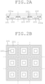
- FIG. 1 is a conceptual view illustrating two joining targets 101 and 102 to be joined to each other by a joining apparatus described below.
- the joining targets 101 and 102 are semiconductor wafers, for example, and have respective joint surfaces 101a and 102a where a first metal layer 201 and a second metal layer 202 are formed respectively.
- the first metal layer 201 is a layer containing one of two types of metals to generate eutectic reaction as a major constituent
- the second metal layer 202 is a layer containing the other metal as a major constituent.
- Examples of a combination of the two types of metals include a combination of aluminum (Al) and germanium (Ge), a combination of copper (Cu) and tin (Sn), a combination of silver (Ag) and tin (Sn), and a combination of indium (In) and tin (Sn). While these layers are not particularly limited, they are formed by vapor deposition or application of the metals to the joint surfaces 101a and 102a.
- FIG. 1 schematically shows a case where the first metal layer 201 is formed on the entire area of the joint surface 101a and the second metal layer 202 is formed on the entire area of the joint surface 101a.
- the first metal layer 201 and the second metal layer 202 are patterned into various shapes in conformity with the shape or purpose of use of a device.
- FIGS. 2(A) and 2(B) are a sectional view and a plan view respectively showing exemplary pattern shapes of the first metal layer 201 and the second metal layer 202.
- FIG. 2(B) shows only the first metal layer 201 in a plan view.
- the first metal layer 201 and the second metal layer 202 are each formed into a quadrangular frame-like shape surrounding one sensor 103.
- the pattern shape of each of the first metal layer 201 and the second metal layer 202 is not limited to a quadrangular frame-like shape but is appropriately changeable in conformity with the shape or purpose of use of a device, for example.
- the joining apparatus described below connects the first metal layer 201 and the second metal layer 202 to each other by utilizing eutectic reaction generated by heating a place of contact between these metal layers with laser light (namely, eutectic bonding using laser light), thereby joining the respective joint surfaces 101a and 102a of the two joining targets 101 and 102 to each other.
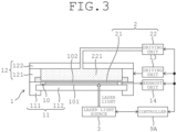
- FIG. 3 is a conceptual view showing a joining apparatus according to a first embodiment.
- the joining apparatus of the present embodiment includes a chamber mechanism 1, a pressurizing mechanism 2, a laser light source 3, and a controller 9A. The configuration of each part will be described below in detail.
- the chamber mechanism 1 includes a first chamber structure unit 11, a second chamber structure unit 12, a driving unit 13, and an exhaust unit 14.
- the first chamber structure unit 11 and the second chamber structure unit 12 are units to form enclosed space (hereinafter called a "chamber 10") for implementation of a joining process.
- the first chamber structure unit 11 and the second chamber structure unit 12 are configured to realize formation and opening of the chamber 10 selectively by getting closer to and away from each other in a vertical direction.
- the first chamber structure unit 11 is composed of a first cylindrical part 111 arranged with a center axis thereof extending in a direction conforming to the vertical direction, and a table 112 supported inside the first cylindrical part 111 horizontally without space between the table 112 and the first cylindrical part 111.
- the table 112 is a table having permeability to laser light, and is a part on which the two joining targets 101 and 102 are to be placed while the first metal layer 201 and the second metal layer 202 face each other (see FIGS. 1 and 2(A) ).
- the table 112 is a table made of quartz.
- the second chamber structure unit 12 is composed of a second cylindrical part 121 arranged over the first cylindrical part 111 and coaxially with the first cylindrical part 111, and a top plate 122 closing an upper end of the second cylindrical part 121.
- An upper end of the first cylindrical part 111 and a lower end of the second cylindrical part 121 contact each other without space therebetween, thereby forming the chamber 10 between the table 112 and the top plate 122.
- the driving unit 13 is a unit that moves at least one of the first chamber structure unit 11 and the second chamber structure unit 12 in the vertical direction, thereby causing these structure units to get closer to and away from each other.
- the exhaust unit 14 is a unit that reduces an air pressure in the chamber 10 until a vacuum state is formed in the chamber 10 (more specifically, space as part of the chamber 10 and defined between a diaphragm 21 described later and the table 112).
- an air pressure adjuster such as a vacuum pump is used as the exhaust unit 14.
- the chamber mechanism 1 may further include a gas supplier that supplies processing gas (such as argon (Ar) gas) into the chamber 10.
- the pressurizing mechanism 2 is a mechanism including the diaphragm 21, and capable of applying pressure to a back surface 102b of the joining target 102 using the diaphragm 21 from an opposite side to the table 112.
- the pressurizing mechanism 2 is composed of the diaphragm 21, and a driving unit 22 that actuates the diaphragm 21. Particulars thereof will be described below.
- the diaphragm 21 is supported inside the second cylindrical part 121 without space between the diaphragm 21 and the second cylindrical part 121 in such a manner that, when the chamber 10 is formed, the diaphragm 21 contacts the back surface 102b of the upper joining target 102 of the two joining targets 101 and 102 placed on the table 112.
- the driving unit 22 transmits pressure to the diaphragm 21 using a pressure medium 221, thereby actuating the diaphragm 21. More specifically, the pressure medium 221 is packed in between the diaphragm 21 and the top plate 122 inside the second chamber structure unit 12. The driving unit 22 changes pressure to be applied to the pressure medium 221, thereby actuating the diaphragm 21 through the pressure medium 221.
- the pressure medium 221 may be liquid or gas.
- the laser light source 3 is a unit that emits laser light.
- the laser light source 3 is arranged below the table 112, and capable of performing a scan with laser light within a horizontal plane along the pattern shapes of the first metal layer 201 and the second metal layer 202 while applying the laser light toward the joining targets 101 and 102 on the table 112.
- the laser light source 3 is capable of focusing the laser light on a place of contact between the first metal layer 201 and the second metal layer 202.
- the controller 9A is composed of a processor such as a central processing unit (CPU) or a microcomputer, and controls various operation units (including the chamber mechanism 1, the pressurizing mechanism 2, and the laser light source 3) of the joining apparatus. Particulars thereof will be described below.
- a processor such as a central processing unit (CPU) or a microcomputer, and controls various operation units (including the chamber mechanism 1, the pressurizing mechanism 2, and the laser light source 3) of the joining apparatus. Particulars thereof will be described below.
- the controller 9A locates the first chamber structure unit 11 and the second chamber structure unit 12 adjacent to each other and unites the first chamber structure unit 11 and the second chamber structure unit 12, thereby forming the chamber 10. Then, the controller 9A controls the exhaust unit 14 to reduce an air pressure in the chamber 10 until a vacuum state is formed in the chamber 10 (more specifically, space as part of the chamber 10 and defined between the diaphragm 21 and the table 112). Furthermore, the controller 9A supplies processing gas (such as argon (Ar) gas) into the chamber 10 according to demand.
- processing gas such as argon (Ar) gas
- the controller 9A thereafter controls the pressurizing mechanism 2 to apply pressure to the back surface 102b of the joining target 102 using the diaphragm 21.
- the diaphragm 21 can be changed flexibly in conformity with the shape of the back surface 102b of the joining target 102 when the pressure is applied to the back surface 102b. This allows the diaphragm 21 to tightly contact the back surface 102b of the joining target 102 and apply the pressure uniformly to the back surface 102b, making it possible to cause deformation (including elastic deformation) of the joining target 102 using the applied pressure.
- the diaphragm 21 follows change in the shape of the back surface 102b resulting from the deformation of the joining target 102, so that the uniform pressure can be applied continuously to the back surface 102b. In this way, the uniform pressure is applied to the back surface 102b of the joining target 102 using the diaphragm 21.
- the joining targets 101 and 102 are wafers having a diameter of 200 mm
- applying pressure with pressing planes to the joining targets 101 and 102 sandwiched between the planes like in Patent Literature 2 requires a load from 3 to 6 tons.
- the pressurization using the diaphragm 21 achieves reduction to a load of equal to or less than 2 tons.
- the controller 9A controls the laser light source 3 while maintaining the resultant state, thereby applying laser light to a place of contact between the first metal layer 201 and the second metal layer 202 through the table 112.
- the controller 9A performs a scan with the laser light within a horizontal plane along the pattern shapes of the first metal layer 201 and the second metal layer 202. By doing so, it becomes possible to connect the first metal layer 201 and the second metal layer 202 to each other over the entire areas of the joining targets 101 and 102 through eutectic bonding. In this way, the respective joint surfaces 101a and 102a of the two joining targets 101 and 102 are joined to each other.
- the pressurization using the diaphragm 21 can reduce a required pressure. This further achieves reduction in strength required for the table 112 (strength enough to withstand pressure applied during joining). As a result, it becomes possible to form the table 112 into a relatively small thickness.
- FIG. 4 is a conceptual view showing a modification of the joining apparatus according to the first embodiment.
- the joining apparatus may further include a heater 4 that heats the joining targets 101 and 102.
- the heater 4 is a heat exchanger composed of a heat exchange part 41 made of a material having high heat conductivity (such as aluminum (Al)), a heating medium 42 that applies heat to the heat exchange part 41, and a temperature adjuster 43 that adjust the temperature of the heating medium 42.
- the heater 4 is arranged on an opposite side to the table 112 with respect to the diaphragm 21.
- the heat exchange part 41 is mounted on an inner surface of the top plate 122, and the heating medium 42 is circulated between the heat exchange part 41 and the temperature adjuster 43 through a hole formed at the top plate 122.
- the pressure medium 221 is interposed between the heat exchange part 41 and the diaphragm 21 and heat is exchanged between the heat exchange part 41 and the diaphragm 21 through the pressure medium 221.
- heat of the heater 4 is transmitted through the pressure medium 221 to the diaphragm 21.
- the controller 9A controls the temperature adjuster 43 to heat the joining targets 101 and 102 through the heat exchange part 41. At this time, the controller 9A heats the joining targets 101 and 102 at a temperature lower than a temperature required for eutectic bonding (eutectic temperature). By doing so, it becomes possible to reduce a temperature width to be increased by heating with the laser light by an amount corresponding to the temperature increase at the place of contact between the first metal layer 201 and the second metal layer 202 achieved by the heating using the heater 4.
- eutectic temperature a temperature required for eutectic bonding
- a temperature required for eutectic bonding is about 450°C.
- eutectic temperature a temperature required for eutectic bonding
- the heater 4 assists in the heating of the contact place with the laser light. In this way, it becomes possible to encourage energy saving through restriction of laser output or increase a processing speed during the joining process, for example.
- Heating by the heater 4 can also be used in an annealing process that alleviates distortions of the joining targets 101 and 102 caused during joining (more specifically, deformation of the joining target 102 caused by pressurization using the diaphragm 21 and left as it is by the joining).
- liquid is preferable to gas for the pressure medium 221.
- the reason for this is that, as liquid has higher heat conductivity than gas, heat is exchanged more efficiently between the heat exchange part 41 and the diaphragm 21 through the pressure medium 221, thereby facilitating transmission of heat of the heater 4 to the diaphragm 21.
- the heating medium 42 is constant-temperature water adjusted to a predetermined temperature (90°C, for example) by the temperature adjuster 43.
- a predetermined temperature 90°C, for example
- the joining apparatus described in the first embodiment is an apparatus not including either chuck mechanisms that hold the joining targets 101 and 102 individually or an alignment mechanism that adjusts the positions of the joining targets 101 and 102 relative to each other. For this reason, the two joining targets 101 and 102 are adjusted in positions relative to each other and overlaid on each other by a different apparatus before joining at the joining apparatus, and then carried and placed onto the table 112. However, carrying the two joining targets 101 and 102 in a state of being overlaid on each other simply causes a risk of misalignment between the adjusted positions of the joining targets 101 and 102 relative to each other due to vibration occurring during the carrying, for example.
- the preliminary joining mentioned herein is performed by connecting the first metal layer 201 and the second metal layer 202 to each other at several places by utilizing eutectic bonding using laser light.
- FIG. 5 is a conceptual view showing the joining apparatus according to a second embodiment.
- the joining apparatus of the present embodiment includes a chuck mechanism 5, an alignment mechanism 6, a pressurizing mechanism 7, a laser light source 8, and a controller 9B. The configuration of each part will be described below in detail.
- the chuck mechanism 5 includes a first chuck unit 51 and a second chuck unit 52.
- the first chuck unit 51 is a table including a suction surface 51a for suction of a back surface 101b of the joining target 101 that is one of the two joining targets 101 and 102.
- the suction surface 51a is provided with a suction groove 51b formed in an entire area of the suction surface 51a.
- the joining target 101 is placed on the suction surface 51a while the back surface 101b is pointed downward and in this state, an air pressure in the suction groove 51b is reduced through vacuum suction, for example. By doing so, it becomes possible to suck the back surface 101b of the joining target 101 to the suction surface 51a.
- the suction surface 51a of the first chuck unit 51 is further provided with through holes 51c formed at several places (five places, for example, and three of them are shown in FIG. 5 ) for passage of laser light.
- a quartz block 511 that compensates for spherical aberration of laser light is buried in each of the through holes 51c.
- the second chuck unit 52 includes a suction surface 52a for suction of the back surface 102b of the other joining target 102 of the two joining targets 101 and 102, and is arranged while the suction surface 52a faces the suction surface 51a of the first chuck unit 51.
- the second chuck unit 52 includes a base body 521 as a foundation thereof.
- the base body 521 has a lower surface 521a where each of parts facing the through holes 51c is composed of a pressure-contact surface 71a belonging to the pressurizing mechanism 7.
- the pressure-contact surface 71a is provided with a suction groove 52b. Particulars thereof will be described below.
- the pressurizing mechanism 7 includes a pressure-contact unit 71 with the pressure-contact surface 71a, and a driving unit 72.
- the pressure-contact unit 71 is provided at each of places of the second chuck unit 52 facing the through holes 51c.
- the pressure-contact unit 71 is provided movably in a direction perpendicular to the lower surface 521a of the base body 521 (here, vertical direction), and is movable to a protruding position where the pressure-contact surface 71a protrudes downward from the lower surface 521a of the base body 521.
- the driving unit 72 is an air cylinder, for example, and allows pressurization to a target brought into contact with the pressure-contact surface 71a. In the present embodiment, the driving unit 72 biases the pressure-contact unit 71 downward to move the pressure-contact unit 71 to the protruding position.
- the pressure-contact surface 71a is brought into contact with the back surface 102b of the joining target 102 and in the contacting state, an air pressure in the suction groove 52b is reduced through vacuum suction, for example. By doing so, the back surface 102b of the joining target 102 is sucked to the pressure-contact surface 71a. In this way, in the present embodiment, the pressure-contact surface 71a with the suction groove 52b forms the suction surface 52a of the second chuck unit 52.
- the two joining targets 101 and 102 are held on (sucked to) the first chuck unit 51 and the second chuck unit 52 respectively as follows.
- the joining target 102 is first placed on the first chuck unit 51 while the back surface 102b of the joining target 102 is pointed upward.
- at least one of the first chuck unit 51 and the second chuck unit 52 is moved in the vertical direction (for example, the second chuck unit 52 is moved down), thereby bringing the pressure-contact surface 71a (suction surface 52a) into contact with the back surface 102b of the joining target 102.
- an air pressure in the suction groove 52b is reduced through vacuum suction, for example.
- the back surface 102b of the joining target 102 is sucked to the pressure-contact surface 71a.
- the first chuck unit 51 and the second chuck unit 52 are thereafter separated from each other (for example, the second chuck unit 52 is moved up), and then the joining target 101 is sucked to the first chuck unit 51.
- the positions of the two joining targets 101 and 102 relative to each other are adjusted by the alignment mechanism 6 descried below.
- at least one of the first chuck unit 51 and the second chuck unit 52 is moved in the vertical direction (for example, the second chuck unit 52 is moved down), thereby bringing the two joining targets 101 and 102 (more specifically, the first metal layer 201 and the second metal layer 202) into contact with each other.
- the first chuck unit 51 and the second chuck unit 52 are brought closer to each other against the biasing force of the driving unit 72 (for example, the second chuck unit 52 is moved down further), thereby applying pressure to the back surface 102b of the joining target 102 through the pressure-contact unit 71.
- pressure can be applied by the pressurizing mechanism 7 to local parts being parts of the back surface 102b of the joining target 102 sucked to the second chuck unit 52 and overlapping the through holes 51c.
- the first metal layer 201 and the second metal layer 202 can contact each other without space therebetween at this local part.
- the alignment mechanism 6 is a mechanism that adjusts the positions of the two joining targets 101 and 102 relative to each other in such a manner as to locate the first metal layer 201 and the second metal layer 202 in a facing relationship while the two joining targets 101 and 102 are held on (sucked to) the first chuck unit 51 and the second chuck unit 52 respectively. More specifically, the alignment mechanism 6 adjusts the position of at least one of the first chuck unit 51 and the second chuck unit 52 in a horizontal plane, thereby allowing the positions of the two joining targets 101 and 102 held on (sucked to) the first chuck unit 51 and the second chuck unit 52 respectively to be adjusted relative to each other.
- the laser light source 8 is a unit that emits laser light.
- the laser light source 8 is arranged below the first chuck unit 51, and applies laser light toward the joining targets 101 and 102 on the first chuck unit 51 through the through hole 51c.
- the laser light source 8 may be configured to pass rays of the laser light simultaneously through a plurality of the through holes 51c formed at the first chuck unit 51, or may be configured to be movable in a horizontal plane and to pass rays of the laser light one by one sequentially through the through holes 51c.
- the laser light source 3 is capable of focusing the laser light on a place of contact between the first metal layer 201 and the second metal layer 202.
- the controller 9B is composed of a processor such as a central processing unit (CPU) or a microcomputer, and controls various operation units (including the chuck mechanism 5, the alignment mechanism 6, the pressurizing mechanism 7, and the laser light source 8) of the joining apparatus. Particulars thereof will be described below.
- a processor such as a central processing unit (CPU) or a microcomputer, and controls various operation units (including the chuck mechanism 5, the alignment mechanism 6, the pressurizing mechanism 7, and the laser light source 8) of the joining apparatus. Particulars thereof will be described below.
- the controller 9B controls the alignment mechanism 6 to adjust the positions of the two joining targets 101 and 102 relative to each other in such a manner as to locate the first metal layer 201 and the second metal layer 202 in a facing relationship.
- the controller 9B moves at least one of the first chuck unit 51 and the second chuck unit 52 in the vertical direction while maintaining the adjusted relative positions, thereby bringing the two joining targets 101 and 102 closer to each other held on (sucked to) the first chuck unit 51 and the second chuck unit 52 respectively to bring the first metal layer 201 and the second metal layer 202 into contact with each other.
- pressure is applied through the pressure-contact unit 71 to local parts being parts of the back surface 102b of the joining target 102 and overlapping the through holes 51c.
- the controller 9B may adjust the pressure to be applied to the local parts by controlling the pressurizing mechanism 7 (more specifically, the driving unit 72) while the first metal layer 201 and the second metal layer 20 contact each other.
- the controller 9B controls the laser light source 3 while maintaining the resultant state, thereby applying laser light to a place of contact between the first metal layer 201 and the second metal layer 202 through the through holes 51c corresponding to the local parts.
- This allows the first metal layer 201 and the second metal layer 202 to be connected to each other through eutectic bonding at several places of the joining targets 101 and 102. In this way, the respective joint surfaces 101a and 102a of the two joining targets 101 and 102 are joined to each other.
- the positions of the two joining targets 101 and 102 relative to each other adjusted by the alignment mechanism 6 are fixed. As a result, even on the occurrence of vibration during carrying, for example, misalignment is still unlikely to occur between the positions of the two joining targets 101 and 102 relative to each other.
- the table 112 and the diaphragm 21 may have respective suction surfaces to which the two joining targets 101 and 102 are to be sucked individually.
- Such a joining apparatus may further include an alignment mechanism that adjusts the positions of the two joining targets 101 and 102 relative to each other held on (sucked to) the table 112 and the diaphragm 21 respectively.
- This alignment mechanism adjusts the position of at least one of the first chamber structure unit 11 and the second chamber structure unit 12 in a horizontal plane, thereby adjusting the positions of the two joining targets 101 and 102 relative to each other sucked to the table 112 and the diaphragm 21 respectively.
- the controller 9A controls the above-described alignment mechanism to adjust the positions of the two joining targets 101 and 102 relative to each other in such a manner as to locate the first metal layer 201 and the second metal layer 202 in a facing relationship. After the relative positions are adjusted by the alignment mechanism, while maintaining the adjusted relative positions, the controller 9A locates the first chamber structure unit 11 and the second chamber structure unit 12 adjacent to each other and unites the first chamber structure unit 11 and the second chamber structure unit 12, thereby forming the chamber 10.
- the two joining targets 101 and 102 held on (sucked to) the table 112 and the diaphragm 21 respectively are brought closer to each other, so that the first metal layer 201 and the second metal layer 202 can be brought into contact with (including adjacency to) each other.
- the controller 9A controls the pressurizing mechanism 2 to apply pressure to the back surface 102b of the joining target 102 using the diaphragm 21. By doing so, the first metal layer 201 and the second metal layer 202 are brought into contact with each other without space therebetween. Then, the controller 9A controls the laser light source 3 while maintaining the resultant state, thereby applying laser light to a place of contact between the first metal layer 201 and the second metal layer 202 through the table 112. The controller 9A performs a scan with the laser light within a horizontal plane along the pattern shapes of the first metal layer 201 and the second metal layer 202.
- the joining apparatus of the present embodiment does not require the preliminary joining described in the second embodiment, thereby achieving simplification of a system as a whole to be used for the joining.
- the above-described joining apparatuses are applicable not only to joining utilizing eutectic reaction (eutectic bonding) but also to various joining types requiring local heating such as solder joining and weld joining.
Landscapes
- Engineering & Computer Science (AREA)
- Physics & Mathematics (AREA)
- Optics & Photonics (AREA)
- Mechanical Engineering (AREA)
- Plasma & Fusion (AREA)
- Manufacturing & Machinery (AREA)
- Microelectronics & Electronic Packaging (AREA)
- Pressure Welding/Diffusion-Bonding (AREA)
- Condensed Matter Physics & Semiconductors (AREA)
- General Physics & Mathematics (AREA)
- Computer Hardware Design (AREA)
- Power Engineering (AREA)
- Health & Medical Sciences (AREA)
- Toxicology (AREA)
- Seal Device For Vehicle (AREA)
- Surgical Instruments (AREA)
- Paper (AREA)
- Lining Or Joining Of Plastics Or The Like (AREA)
- Laser Beam Processing (AREA)
Applications Claiming Priority (2)
| Application Number | Priority Date | Filing Date | Title |
|---|---|---|---|
| JP2020189436A JP7608120B2 (ja) | 2020-11-13 | 2020-11-13 | 接合装置 |
| PCT/JP2021/032690 WO2022102228A1 (ja) | 2020-11-13 | 2021-09-06 | 接合装置 |
Publications (2)
| Publication Number | Publication Date |
|---|---|
| EP4245451A1 true EP4245451A1 (de) | 2023-09-20 |
| EP4245451A4 EP4245451A4 (de) | 2024-10-16 |
Family
ID=81601852
Family Applications (1)
| Application Number | Title | Priority Date | Filing Date |
|---|---|---|---|
| EP21891476.0A Pending EP4245451A4 (de) | 2020-11-13 | 2021-09-06 | Fügevorrichtung |
Country Status (7)
| Country | Link |
|---|---|
| US (1) | US20240009769A1 (de) |
| EP (1) | EP4245451A4 (de) |
| JP (2) | JP7608120B2 (de) |
| KR (1) | KR102844379B1 (de) |
| CN (1) | CN116367949A (de) |
| TW (1) | TWI821747B (de) |
| WO (1) | WO2022102228A1 (de) |
Families Citing this family (6)
| Publication number | Priority date | Publication date | Assignee | Title |
|---|---|---|---|---|
| JP7688605B2 (ja) * | 2022-06-08 | 2025-06-04 | タツモ株式会社 | 接合装置 |
| JP2024085189A (ja) * | 2022-12-14 | 2024-06-26 | タツモ株式会社 | 半導体デバイスの製造方法 |
| KR102852524B1 (ko) * | 2023-03-21 | 2025-08-29 | 주식회사 렉스피 | 마이크로 led 전사 및 접합용 기구 및 그 운용 방법 |
| JP2024164367A (ja) * | 2023-05-15 | 2024-11-27 | タツモ株式会社 | 接合修復方法 |
| JP7695433B1 (ja) * | 2024-03-08 | 2025-06-18 | タツモ株式会社 | 貼合装置 |
| WO2026024107A1 (ko) * | 2024-07-24 | 2026-01-29 | 주식회사 아모그린텍 | 공압을 이용한 전자부품 접합방법 |
Family Cites Families (17)
| Publication number | Priority date | Publication date | Assignee | Title |
|---|---|---|---|---|
| JP2004343042A (ja) | 2003-04-25 | 2004-12-02 | Nippon Steel Chem Co Ltd | 電子装置の製造方法 |
| DE50306765D1 (de) * | 2003-12-10 | 2007-04-19 | Trumpf Laser & Systemtechnik | Laserbearbeitungsmaschine und Verfahren mittels Laserbearbeitung |
| JP5282100B2 (ja) * | 2008-11-14 | 2013-09-04 | 東京エレクトロン株式会社 | 貼り合わせ装置及び貼り合わせ方法 |
| JP5571988B2 (ja) | 2010-03-26 | 2014-08-13 | パナソニック株式会社 | 接合方法 |
| US20110309057A1 (en) | 2010-06-21 | 2011-12-22 | Touch Micro-System Technology Corp. | Laser heating apparatus for metal eutectic bonding |
| US8796109B2 (en) * | 2010-12-23 | 2014-08-05 | Medtronic, Inc. | Techniques for bonding substrates using an intermediate layer |
| JP6037734B2 (ja) * | 2012-09-07 | 2016-12-07 | 三菱重工工作機械株式会社 | 常温接合装置および常温接合方法 |
| JP2014063963A (ja) | 2012-09-24 | 2014-04-10 | Murata Mfg Co Ltd | 電子部品の製造方法 |
| EP2957379B1 (de) * | 2013-02-15 | 2019-04-10 | Nissan Motor Co., Ltd | Laserschweissverfahren und laserschweissvorrichtung |
| EP3208828A4 (de) * | 2014-10-17 | 2018-06-06 | Bondtech Co., Ltd. | Verfahren zum verbinden von substraten und substratverklebungsvorrichtung |
| SG11201704557PA (en) * | 2014-12-23 | 2017-07-28 | Ev Group E Thallner Gmbh | Method and device for prefixing substrates |
| JP6459930B2 (ja) * | 2015-11-27 | 2019-01-30 | オムロン株式会社 | 接合構造体の製造方法および接合構造体 |
| WO2019054368A1 (ja) * | 2017-09-15 | 2019-03-21 | 国立研究開発法人産業技術総合研究所 | 基板の接合方法及び封止構造 |
| JP7051455B2 (ja) * | 2018-01-16 | 2022-04-11 | キオクシア株式会社 | パターン形成装置および半導体装置の製造方法 |
| TWI735895B (zh) * | 2018-06-22 | 2021-08-11 | 瑞士商G射線工業公司 | 共價接合之半導體界面 |
| US20200176414A1 (en) * | 2018-12-03 | 2020-06-04 | Jtekt Corporation | Joint device and control method for joint device |
| CN210223961U (zh) | 2019-01-23 | 2020-03-31 | 爱莱私人有限公司 | 一种室温晶圆共晶键合的硬件配置及模块和系统 |
-
2020
- 2020-11-13 JP JP2020189436A patent/JP7608120B2/ja active Active
-
2021
- 2021-09-06 WO PCT/JP2021/032690 patent/WO2022102228A1/ja not_active Ceased
- 2021-09-06 EP EP21891476.0A patent/EP4245451A4/de active Pending
- 2021-09-06 KR KR1020237012860A patent/KR102844379B1/ko active Active
- 2021-09-06 CN CN202180070616.4A patent/CN116367949A/zh active Pending
- 2021-09-06 US US18/035,133 patent/US20240009769A1/en active Pending
- 2021-09-17 TW TW110134721A patent/TWI821747B/zh active
-
2022
- 2022-07-07 JP JP2022109773A patent/JP7608400B2/ja active Active
Also Published As
| Publication number | Publication date |
|---|---|
| US20240009769A1 (en) | 2024-01-11 |
| JP7608400B2 (ja) | 2025-01-06 |
| JP7608120B2 (ja) | 2025-01-06 |
| CN116367949A (zh) | 2023-06-30 |
| JP2022078625A (ja) | 2022-05-25 |
| JP2022141756A (ja) | 2022-09-29 |
| WO2022102228A1 (ja) | 2022-05-19 |
| TWI821747B (zh) | 2023-11-11 |
| TW202233513A (zh) | 2022-09-01 |
| EP4245451A4 (de) | 2024-10-16 |
| KR20230066630A (ko) | 2023-05-16 |
| KR102844379B1 (ko) | 2025-08-07 |
Similar Documents
| Publication | Publication Date | Title |
|---|---|---|
| EP4245451A1 (de) | Fügevorrichtung | |
| JP5390380B2 (ja) | 半導体接合のための装置及び方法 | |
| US5370301A (en) | Apparatus and method for flip-chip bonding | |
| US20110214809A1 (en) | Bonding apparatus and bonding method | |
| CN210223961U (zh) | 一种室温晶圆共晶键合的硬件配置及模块和系统 | |
| US8490856B2 (en) | Joint apparatus, joint method, and computer storage medium | |
| JP2017022364A (ja) | 整列したウェーハ・ペアを取り扱うための方法 | |
| CN109599350A (zh) | 激光辅助接合装置及半导体组件的制造方法 | |
| JP4961342B2 (ja) | 2つのウエハの相互接触のための方法および装置 | |
| US20250326056A1 (en) | Joining apparatus | |
| JP2009141043A (ja) | 支持装置、加熱加圧装置及び加熱加圧方法 | |
| TWI630048B (zh) | Bonding device, bonding system, bonding method, and computer memory medium | |
| JP2001287025A (ja) | 温度制御装置の製造方法 | |
| EP4539097A1 (de) | Verbindungsverfahren | |
| JP7695433B1 (ja) | 貼合装置 | |
| JP2015066557A (ja) | 加圧治具 | |
| TW202135968A (zh) | 接合設備、接合系統及接合方法 | |
| JP2002151642A (ja) | 半導体装置の製造方法 | |
| JP2012004322A (ja) | 基板貼り合せ装置、積層半導体装置製造方法及び積層半導体装置 | |
| JPH10144731A (ja) | 半導体装置の製造方法 | |
| JPH10321152A (ja) | イオン加速電極板及びその製造方法 | |
| JP2014241416A (ja) | 基板貼り合せ装置および積層半導体装置製造方法 |
Legal Events
| Date | Code | Title | Description |
|---|---|---|---|
| STAA | Information on the status of an ep patent application or granted ep patent |
Free format text: STATUS: THE INTERNATIONAL PUBLICATION HAS BEEN MADE |
|
| PUAI | Public reference made under article 153(3) epc to a published international application that has entered the european phase |
Free format text: ORIGINAL CODE: 0009012 |
|
| STAA | Information on the status of an ep patent application or granted ep patent |
Free format text: STATUS: REQUEST FOR EXAMINATION WAS MADE |
|
| 17P | Request for examination filed |
Effective date: 20230512 |
|
| AK | Designated contracting states |
Kind code of ref document: A1 Designated state(s): AL AT BE BG CH CY CZ DE DK EE ES FI FR GB GR HR HU IE IS IT LI LT LU LV MC MK MT NL NO PL PT RO RS SE SI SK SM TR |
|
| DAV | Request for validation of the european patent (deleted) | ||
| DAX | Request for extension of the european patent (deleted) | ||
| REG | Reference to a national code |
Ref country code: DE Ref legal event code: R079 Free format text: PREVIOUS MAIN CLASS: B23K0020000000 Ipc: B81C0099000000 |
|
| A4 | Supplementary search report drawn up and despatched |
Effective date: 20240918 |
|
| RIC1 | Information provided on ipc code assigned before grant |
Ipc: H01L 21/67 20060101ALI20240912BHEP Ipc: B23K 37/04 20060101ALI20240912BHEP Ipc: B23K 26/70 20140101ALI20240912BHEP Ipc: B23K 26/324 20140101ALI20240912BHEP Ipc: B23K 26/21 20140101ALI20240912BHEP Ipc: B23K 26/12 20140101ALI20240912BHEP Ipc: B81C 99/00 20100101AFI20240912BHEP |