EP4243451A1 - Impedanzvorrichtungen und systeme zur simulation der auswirkung eines kopfes auf die vibration einer vibrationseinheit - Google Patents
Impedanzvorrichtungen und systeme zur simulation der auswirkung eines kopfes auf die vibration einer vibrationseinheit Download PDFInfo
- Publication number
- EP4243451A1 EP4243451A1 EP22899614.6A EP22899614A EP4243451A1 EP 4243451 A1 EP4243451 A1 EP 4243451A1 EP 22899614 A EP22899614 A EP 22899614A EP 4243451 A1 EP4243451 A1 EP 4243451A1
- Authority
- EP
- European Patent Office
- Prior art keywords
- impedance device
- elastic
- vibration unit
- vibration
- fixing part
- Prior art date
- Legal status (The legal status is an assumption and is not a legal conclusion. Google has not performed a legal analysis and makes no representation as to the accuracy of the status listed.)
- Pending
Links
- 238000013016 damping Methods 0.000 claims description 130
- 229910052751 metal Inorganic materials 0.000 claims description 25
- 239000002184 metal Substances 0.000 claims description 25
- 238000000034 method Methods 0.000 claims description 17
- 230000008878 coupling Effects 0.000 claims description 16
- 238000010168 coupling process Methods 0.000 claims description 16
- 238000005859 coupling reaction Methods 0.000 claims description 16
- 230000008569 process Effects 0.000 claims description 13
- 235000014676 Phragmites communis Nutrition 0.000 claims description 12
- 238000006073 displacement reaction Methods 0.000 claims description 10
- 230000004907 flux Effects 0.000 claims description 4
- 230000002093 peripheral effect Effects 0.000 claims description 4
- 210000003128 head Anatomy 0.000 description 59
- 241000746998 Tragus Species 0.000 description 40
- 230000004044 response Effects 0.000 description 34
- 238000010586 diagram Methods 0.000 description 27
- 239000000463 material Substances 0.000 description 22
- 230000009471 action Effects 0.000 description 12
- 238000012986 modification Methods 0.000 description 12
- 230000004048 modification Effects 0.000 description 12
- 210000000988 bone and bone Anatomy 0.000 description 8
- 230000001815 facial effect Effects 0.000 description 8
- 239000012530 fluid Substances 0.000 description 8
- 239000006260 foam Substances 0.000 description 7
- 235000019589 hardness Nutrition 0.000 description 7
- 239000004642 Polyimide Substances 0.000 description 6
- 239000004372 Polyvinyl alcohol Substances 0.000 description 6
- 229920001971 elastomer Polymers 0.000 description 6
- 230000006870 function Effects 0.000 description 6
- 229920000728 polyester Polymers 0.000 description 6
- 229920001721 polyimide Polymers 0.000 description 6
- 229920001296 polysiloxane Polymers 0.000 description 6
- 229920002451 polyvinyl alcohol Polymers 0.000 description 6
- 238000012360 testing method Methods 0.000 description 6
- 230000000694 effects Effects 0.000 description 5
- 239000007788 liquid Substances 0.000 description 5
- 239000011148 porous material Substances 0.000 description 5
- 230000001133 acceleration Effects 0.000 description 4
- 238000006243 chemical reaction Methods 0.000 description 4
- 230000005489 elastic deformation Effects 0.000 description 4
- 210000001595 mastoid Anatomy 0.000 description 4
- 229920003023 plastic Polymers 0.000 description 4
- 239000004033 plastic Substances 0.000 description 4
- 238000007920 subcutaneous administration Methods 0.000 description 4
- 230000009286 beneficial effect Effects 0.000 description 3
- 230000007423 decrease Effects 0.000 description 3
- 239000007769 metal material Substances 0.000 description 3
- 230000003287 optical effect Effects 0.000 description 3
- 239000011112 polyethylene naphthalate Substances 0.000 description 3
- 239000004753 textile Substances 0.000 description 3
- 102000008186 Collagen Human genes 0.000 description 2
- 108010035532 Collagen Proteins 0.000 description 2
- 102000016942 Elastin Human genes 0.000 description 2
- 108010014258 Elastin Proteins 0.000 description 2
- XEEYBQQBJWHFJM-UHFFFAOYSA-N Iron Chemical compound [Fe] XEEYBQQBJWHFJM-UHFFFAOYSA-N 0.000 description 2
- VYPSYNLAJGMNEJ-UHFFFAOYSA-N Silicium dioxide Chemical compound O=[Si]=O VYPSYNLAJGMNEJ-UHFFFAOYSA-N 0.000 description 2
- 229920001436 collagen Polymers 0.000 description 2
- 238000011161 development Methods 0.000 description 2
- 229920002549 elastin Polymers 0.000 description 2
- 210000001061 forehead Anatomy 0.000 description 2
- 239000011521 glass Substances 0.000 description 2
- 230000001788 irregular Effects 0.000 description 2
- 239000011553 magnetic fluid Substances 0.000 description 2
- 238000004519 manufacturing process Methods 0.000 description 2
- BASFCYQUMIYNBI-UHFFFAOYSA-N platinum Chemical compound [Pt] BASFCYQUMIYNBI-UHFFFAOYSA-N 0.000 description 2
- 239000000741 silica gel Substances 0.000 description 2
- 229910002027 silica gel Inorganic materials 0.000 description 2
- 229920002379 silicone rubber Polymers 0.000 description 2
- 238000004088 simulation Methods 0.000 description 2
- 238000003860 storage Methods 0.000 description 2
- 239000000725 suspension Substances 0.000 description 2
- 210000003582 temporal bone Anatomy 0.000 description 2
- 210000003454 tympanic membrane Anatomy 0.000 description 2
- JBRZTFJDHDCESZ-UHFFFAOYSA-N AsGa Chemical compound [As]#[Ga] JBRZTFJDHDCESZ-UHFFFAOYSA-N 0.000 description 1
- OKTJSMMVPCPJKN-UHFFFAOYSA-N Carbon Chemical compound [C] OKTJSMMVPCPJKN-UHFFFAOYSA-N 0.000 description 1
- RYGMFSIKBFXOCR-UHFFFAOYSA-N Copper Chemical compound [Cu] RYGMFSIKBFXOCR-UHFFFAOYSA-N 0.000 description 1
- 229910001218 Gallium arsenide Inorganic materials 0.000 description 1
- BUGBHKTXTAQXES-UHFFFAOYSA-N Selenium Chemical compound [Se] BUGBHKTXTAQXES-UHFFFAOYSA-N 0.000 description 1
- XUIMIQQOPSSXEZ-UHFFFAOYSA-N Silicon Chemical compound [Si] XUIMIQQOPSSXEZ-UHFFFAOYSA-N 0.000 description 1
- 238000004026 adhesive bonding Methods 0.000 description 1
- 229910052782 aluminium Inorganic materials 0.000 description 1
- XAGFODPZIPBFFR-UHFFFAOYSA-N aluminium Chemical compound [Al] XAGFODPZIPBFFR-UHFFFAOYSA-N 0.000 description 1
- 230000000712 assembly Effects 0.000 description 1
- 238000000429 assembly Methods 0.000 description 1
- DMFGNRRURHSENX-UHFFFAOYSA-N beryllium copper Chemical compound [Be].[Cu] DMFGNRRURHSENX-UHFFFAOYSA-N 0.000 description 1
- 238000004364 calculation method Methods 0.000 description 1
- 230000008859 change Effects 0.000 description 1
- 210000003477 cochlea Anatomy 0.000 description 1
- 230000006835 compression Effects 0.000 description 1
- 238000007906 compression Methods 0.000 description 1
- 229910052802 copper Inorganic materials 0.000 description 1
- 239000010949 copper Substances 0.000 description 1
- 238000012937 correction Methods 0.000 description 1
- 230000003111 delayed effect Effects 0.000 description 1
- 238000001514 detection method Methods 0.000 description 1
- 210000000613 ear canal Anatomy 0.000 description 1
- 210000003027 ear inner Anatomy 0.000 description 1
- 210000000959 ear middle Anatomy 0.000 description 1
- 210000003094 ear ossicle Anatomy 0.000 description 1
- 239000004744 fabric Substances 0.000 description 1
- 230000014509 gene expression Effects 0.000 description 1
- 229910052732 germanium Inorganic materials 0.000 description 1
- GNPVGFCGXDBREM-UHFFFAOYSA-N germanium atom Chemical compound [Ge] GNPVGFCGXDBREM-UHFFFAOYSA-N 0.000 description 1
- PCHJSUWPFVWCPO-UHFFFAOYSA-N gold Chemical compound [Au] PCHJSUWPFVWCPO-UHFFFAOYSA-N 0.000 description 1
- 229910052737 gold Inorganic materials 0.000 description 1
- 239000010931 gold Substances 0.000 description 1
- 229910002804 graphite Inorganic materials 0.000 description 1
- 239000010439 graphite Substances 0.000 description 1
- 238000009434 installation Methods 0.000 description 1
- 229910052742 iron Inorganic materials 0.000 description 1
- 239000000203 mixture Substances 0.000 description 1
- 239000003607 modifier Substances 0.000 description 1
- 238000000465 moulding Methods 0.000 description 1
- 239000005416 organic matter Substances 0.000 description 1
- 229910052697 platinum Inorganic materials 0.000 description 1
- 230000001681 protective effect Effects 0.000 description 1
- 230000010349 pulsation Effects 0.000 description 1
- 239000011669 selenium Substances 0.000 description 1
- 229910052711 selenium Inorganic materials 0.000 description 1
- 239000004065 semiconductor Substances 0.000 description 1
- 229910052710 silicon Inorganic materials 0.000 description 1
- 239000010703 silicon Substances 0.000 description 1
- HBMJWWWQQXIZIP-UHFFFAOYSA-N silicon carbide Chemical compound [Si+]#[C-] HBMJWWWQQXIZIP-UHFFFAOYSA-N 0.000 description 1
- 229910010271 silicon carbide Inorganic materials 0.000 description 1
- 229910052709 silver Inorganic materials 0.000 description 1
- 239000004332 silver Substances 0.000 description 1
- 210000003625 skull Anatomy 0.000 description 1
- 229910001220 stainless steel Inorganic materials 0.000 description 1
- 239000010935 stainless steel Substances 0.000 description 1
- XLYOFNOQVPJJNP-UHFFFAOYSA-N water Substances O XLYOFNOQVPJJNP-UHFFFAOYSA-N 0.000 description 1
- 238000003466 welding Methods 0.000 description 1
- 239000002023 wood Substances 0.000 description 1
Images


Classifications
-
- H—ELECTRICITY
- H04—ELECTRIC COMMUNICATION TECHNIQUE
- H04R—LOUDSPEAKERS, MICROPHONES, GRAMOPHONE PICK-UPS OR LIKE ACOUSTIC ELECTROMECHANICAL TRANSDUCERS; DEAF-AID SETS; PUBLIC ADDRESS SYSTEMS
- H04R1/00—Details of transducers, loudspeakers or microphones
- H04R1/10—Earpieces; Attachments therefor ; Earphones; Monophonic headphones
- H04R1/1058—Manufacture or assembly
- H04R1/1075—Mountings of transducers in earphones or headphones
-
- H—ELECTRICITY
- H04—ELECTRIC COMMUNICATION TECHNIQUE
- H04R—LOUDSPEAKERS, MICROPHONES, GRAMOPHONE PICK-UPS OR LIKE ACOUSTIC ELECTROMECHANICAL TRANSDUCERS; DEAF-AID SETS; PUBLIC ADDRESS SYSTEMS
- H04R25/00—Deaf-aid sets, i.e. electro-acoustic or electro-mechanical hearing aids; Electric tinnitus maskers providing an auditory perception
- H04R25/50—Customised settings for obtaining desired overall acoustical characteristics
-
- H—ELECTRICITY
- H04—ELECTRIC COMMUNICATION TECHNIQUE
- H04R—LOUDSPEAKERS, MICROPHONES, GRAMOPHONE PICK-UPS OR LIKE ACOUSTIC ELECTROMECHANICAL TRANSDUCERS; DEAF-AID SETS; PUBLIC ADDRESS SYSTEMS
- H04R1/00—Details of transducers, loudspeakers or microphones
- H04R1/20—Arrangements for obtaining desired frequency or directional characteristics
- H04R1/22—Arrangements for obtaining desired frequency or directional characteristics for obtaining desired frequency characteristic only
- H04R1/28—Transducer mountings or enclosures modified by provision of mechanical or acoustic impedances, e.g. resonator, damping means
- H04R1/2869—Reduction of undesired resonances, i.e. standing waves within enclosure, or of undesired vibrations, i.e. of the enclosure itself
- H04R1/2876—Reduction of undesired resonances, i.e. standing waves within enclosure, or of undesired vibrations, i.e. of the enclosure itself by means of damping material, e.g. as cladding
- H04R1/288—Reduction of undesired resonances, i.e. standing waves within enclosure, or of undesired vibrations, i.e. of the enclosure itself by means of damping material, e.g. as cladding for loudspeaker transducers
-
- G—PHYSICS
- G08—SIGNALLING
- G08B—SIGNALLING OR CALLING SYSTEMS; ORDER TELEGRAPHS; ALARM SYSTEMS
- G08B6/00—Tactile signalling systems, e.g. personal calling systems
-
- H—ELECTRICITY
- H03—ELECTRONIC CIRCUITRY
- H03G—CONTROL OF AMPLIFICATION
- H03G5/00—Tone control or bandwidth control in amplifiers
- H03G5/16—Automatic control
- H03G5/165—Equalizers; Volume or gain control in limited frequency bands
-
- H—ELECTRICITY
- H04—ELECTRIC COMMUNICATION TECHNIQUE
- H04R—LOUDSPEAKERS, MICROPHONES, GRAMOPHONE PICK-UPS OR LIKE ACOUSTIC ELECTROMECHANICAL TRANSDUCERS; DEAF-AID SETS; PUBLIC ADDRESS SYSTEMS
- H04R1/00—Details of transducers, loudspeakers or microphones
- H04R1/10—Earpieces; Attachments therefor ; Earphones; Monophonic headphones
- H04R1/1008—Earpieces of the supra-aural or circum-aural type
-
- H—ELECTRICITY
- H04—ELECTRIC COMMUNICATION TECHNIQUE
- H04R—LOUDSPEAKERS, MICROPHONES, GRAMOPHONE PICK-UPS OR LIKE ACOUSTIC ELECTROMECHANICAL TRANSDUCERS; DEAF-AID SETS; PUBLIC ADDRESS SYSTEMS
- H04R1/00—Details of transducers, loudspeakers or microphones
- H04R1/10—Earpieces; Attachments therefor ; Earphones; Monophonic headphones
- H04R1/1041—Mechanical or electronic switches, or control elements
-
- H—ELECTRICITY
- H04—ELECTRIC COMMUNICATION TECHNIQUE
- H04R—LOUDSPEAKERS, MICROPHONES, GRAMOPHONE PICK-UPS OR LIKE ACOUSTIC ELECTROMECHANICAL TRANSDUCERS; DEAF-AID SETS; PUBLIC ADDRESS SYSTEMS
- H04R1/00—Details of transducers, loudspeakers or microphones
- H04R1/10—Earpieces; Attachments therefor ; Earphones; Monophonic headphones
- H04R1/105—Earpiece supports, e.g. ear hooks
-
- H—ELECTRICITY
- H04—ELECTRIC COMMUNICATION TECHNIQUE
- H04R—LOUDSPEAKERS, MICROPHONES, GRAMOPHONE PICK-UPS OR LIKE ACOUSTIC ELECTROMECHANICAL TRANSDUCERS; DEAF-AID SETS; PUBLIC ADDRESS SYSTEMS
- H04R1/00—Details of transducers, loudspeakers or microphones
- H04R1/10—Earpieces; Attachments therefor ; Earphones; Monophonic headphones
- H04R1/1091—Details not provided for in groups H04R1/1008 - H04R1/1083
-
- H—ELECTRICITY
- H04—ELECTRIC COMMUNICATION TECHNIQUE
- H04R—LOUDSPEAKERS, MICROPHONES, GRAMOPHONE PICK-UPS OR LIKE ACOUSTIC ELECTROMECHANICAL TRANSDUCERS; DEAF-AID SETS; PUBLIC ADDRESS SYSTEMS
- H04R25/00—Deaf-aid sets, i.e. electro-acoustic or electro-mechanical hearing aids; Electric tinnitus maskers providing an auditory perception
- H04R25/60—Mounting or interconnection of hearing aid parts, e.g. inside tips, housings or to ossicles
- H04R25/607—Mounting or interconnection of hearing aid parts, e.g. inside tips, housings or to ossicles of earhooks
-
- H—ELECTRICITY
- H04—ELECTRIC COMMUNICATION TECHNIQUE
- H04R—LOUDSPEAKERS, MICROPHONES, GRAMOPHONE PICK-UPS OR LIKE ACOUSTIC ELECTROMECHANICAL TRANSDUCERS; DEAF-AID SETS; PUBLIC ADDRESS SYSTEMS
- H04R29/00—Monitoring arrangements; Testing arrangements
- H04R29/001—Monitoring arrangements; Testing arrangements for loudspeakers
-
- H—ELECTRICITY
- H04—ELECTRIC COMMUNICATION TECHNIQUE
- H04R—LOUDSPEAKERS, MICROPHONES, GRAMOPHONE PICK-UPS OR LIKE ACOUSTIC ELECTROMECHANICAL TRANSDUCERS; DEAF-AID SETS; PUBLIC ADDRESS SYSTEMS
- H04R3/00—Circuits for transducers, loudspeakers or microphones
- H04R3/02—Circuits for transducers, loudspeakers or microphones for preventing acoustic reaction, i.e. acoustic oscillatory feedback
-
- H—ELECTRICITY
- H04—ELECTRIC COMMUNICATION TECHNIQUE
- H04R—LOUDSPEAKERS, MICROPHONES, GRAMOPHONE PICK-UPS OR LIKE ACOUSTIC ELECTROMECHANICAL TRANSDUCERS; DEAF-AID SETS; PUBLIC ADDRESS SYSTEMS
- H04R9/00—Transducers of moving-coil, moving-strip, or moving-wire type
- H04R9/02—Details
-
- H—ELECTRICITY
- H04—ELECTRIC COMMUNICATION TECHNIQUE
- H04R—LOUDSPEAKERS, MICROPHONES, GRAMOPHONE PICK-UPS OR LIKE ACOUSTIC ELECTROMECHANICAL TRANSDUCERS; DEAF-AID SETS; PUBLIC ADDRESS SYSTEMS
- H04R9/00—Transducers of moving-coil, moving-strip, or moving-wire type
- H04R9/06—Loudspeakers
-
- H—ELECTRICITY
- H04—ELECTRIC COMMUNICATION TECHNIQUE
- H04R—LOUDSPEAKERS, MICROPHONES, GRAMOPHONE PICK-UPS OR LIKE ACOUSTIC ELECTROMECHANICAL TRANSDUCERS; DEAF-AID SETS; PUBLIC ADDRESS SYSTEMS
- H04R1/00—Details of transducers, loudspeakers or microphones
- H04R1/02—Casings; Cabinets ; Supports therefor; Mountings therein
- H04R1/025—Arrangements for fixing loudspeaker transducers, e.g. in a box, furniture
-
- H—ELECTRICITY
- H04—ELECTRIC COMMUNICATION TECHNIQUE
- H04R—LOUDSPEAKERS, MICROPHONES, GRAMOPHONE PICK-UPS OR LIKE ACOUSTIC ELECTROMECHANICAL TRANSDUCERS; DEAF-AID SETS; PUBLIC ADDRESS SYSTEMS
- H04R1/00—Details of transducers, loudspeakers or microphones
- H04R1/20—Arrangements for obtaining desired frequency or directional characteristics
- H04R1/22—Arrangements for obtaining desired frequency or directional characteristics for obtaining desired frequency characteristic only
- H04R1/28—Transducer mountings or enclosures modified by provision of mechanical or acoustic impedances, e.g. resonator, damping means
- H04R1/2807—Enclosures comprising vibrating or resonating arrangements
- H04R1/2811—Enclosures comprising vibrating or resonating arrangements for loudspeaker transducers
-
- H—ELECTRICITY
- H04—ELECTRIC COMMUNICATION TECHNIQUE
- H04R—LOUDSPEAKERS, MICROPHONES, GRAMOPHONE PICK-UPS OR LIKE ACOUSTIC ELECTROMECHANICAL TRANSDUCERS; DEAF-AID SETS; PUBLIC ADDRESS SYSTEMS
- H04R2225/00—Details of deaf aids covered by H04R25/00, not provided for in any of its subgroups
- H04R2225/43—Signal processing in hearing aids to enhance the speech intelligibility
-
- H—ELECTRICITY
- H04—ELECTRIC COMMUNICATION TECHNIQUE
- H04R—LOUDSPEAKERS, MICROPHONES, GRAMOPHONE PICK-UPS OR LIKE ACOUSTIC ELECTROMECHANICAL TRANSDUCERS; DEAF-AID SETS; PUBLIC ADDRESS SYSTEMS
- H04R2460/00—Details of hearing devices, i.e. of ear- or headphones covered by H04R1/10 or H04R5/033 but not provided for in any of their subgroups, or of hearing aids covered by H04R25/00 but not provided for in any of its subgroups
- H04R2460/13—Hearing devices using bone conduction transducers
-
- H—ELECTRICITY
- H04—ELECTRIC COMMUNICATION TECHNIQUE
- H04R—LOUDSPEAKERS, MICROPHONES, GRAMOPHONE PICK-UPS OR LIKE ACOUSTIC ELECTROMECHANICAL TRANSDUCERS; DEAF-AID SETS; PUBLIC ADDRESS SYSTEMS
- H04R3/00—Circuits for transducers, loudspeakers or microphones
- H04R3/04—Circuits for transducers, loudspeakers or microphones for correcting frequency response
Definitions
- the present disclosure relates to the field of vibration simulation, in particular to an impedance device and a system for simulating an impact of a head on a vibration of a vibration unit.
- a vibration unit may generate a vibration signal to transmit the vibration signal to a human head (e.g., head bones).
- a human head e.g., head bones
- the vibration unit when used as a bone conduction earphone or a hearing aid, the vibration unit is fitted to a facial area on the front side of a user's auricle, and a bone hardness of this area in the human head is lower than that of a skull, a mastoid bone, etc., which means that a mechanical impedance of the facial area on the front side of the user's auricle is significantly different from that of other parts of the human head.
- the existing device that simulates the human head usually simulates the mechanical impedance of the mastoid behind the user's ear. Obviously, with the existing device, the simulation scenario where the vibration unit fits the facial area on the front side of the human auricle cannot be satisfied.
- the impedance device includes a mass part, an elastic part, and a fixing part.
- the mass part is connected to the fixing part through the elastic part.
- the fixing part is a hollow structure and includes an opening.
- the elastic part is located at the opening and connected to the fixing part, and the elastic part and the fixing part form a cavity.
- An elastic coefficient of the elastic part in a vibration direction in which the mass part vibrates relative to the fixing part is in a range of 600 N/m ⁇ 5000 N/m.
- One of the embodiments of the present disclosure further provides a system for simulating an impact of a head on a vibration of a vibration unit.
- the system includes a vibration unit configured to provide a vibration signal, an impedance configured to contact the vibration unit and provide a mechanical impedance to the vibration unit, a connection part configured to couple the vibration unit to the impedance device, and a sensor configured to collect parameter information of the vibration unit during a vibration process.
- the impedance device includes a mass part, an elastic part, and a fixing part.
- the mass part is connected to the fixing part through the elastic part.
- the fixing part is a hollow structure including an opening.
- the elastic part is located at the opening and is connected to the fixing part.
- the elastic part forms a cavity with the fixing part.
- An elastic coefficient of the elastic part in a vibration direction in which the mass part vibrates relative to the fixing part is in a range of 600 N/m ⁇ 5000 N/m.
- system is a method for distinguishing different parts, elements, parts, part s or assemblies of different levels.
- words may be replaced by other expressions if the other words can accomplish the same purpose.
- the impedance device may include a mass part, an elastic part and a fixing part, and the mass part is connected to the fixing part through the elastic part.
- the fixing part is a hollow structure including an opening
- the elastic part is located at the opening and connected with the fixing part
- the elastic part and the fixing part form a cavity.
- the mass part is connected to the elastic part, and under an action of an external force, the mass part may vibrate relative to the fixing part.
- an elastic coefficient of the elastic part in a vibration direction in which the mass part vibrates relative to the fixing part is in a range of 600 N/m to 5000 N/m.
- the vibration of the mass part relative to the fixing part has a resonance peak within a frequency range of 20 Hz-300 Hz.
- a frequency response curve of the vibration unit (e.g., a bone conduction speaker, a hearing aid, etc.) when the vibration unit is coupled with the mass part of the impedance device and a frequency response curve when the vibration unit is worn near a tragus area of the human body (e.g., a facial area in front of the auricle) are approximately the same, and the impedance device may be used to simulate the impact on the vibration unit near the tragus area.
- the impedance device may further include a damping structure.
- the damping structure may provide a damping for the impedance device, and the damping of the damping structure may be adjusted to simulate an actual impedance fed back to the vibration unit near the tragus area during an actual use, so that the frequency response curve when the vibration unit is coupled with the impedance device is the same or approximately the same with the frequency response curve of the vibration unit when the vibration unit is worn near the tragus area of the human body.
- FIG. 1 is a block diagram illustrating an impedance device according to some embodiments of the present disclosure.
- an impedance device 100 may include a mass part 101, an elastic part 102, and a fixing part 103.
- the mass part 101 is connected to the fixing part 103 through the elastic part 102, and the mass part 101 may vibrate relative to the fixing part 103.
- the mass part 101 may be physically connected to the fixing part 103 through the elastic part 102, and the physical connection described in the present disclosure may include a welding, a clamping, a gluing, an integral molding, or the like, or any combination thereof.
- the mass part 101 when the mass part 101 contacts or couples with an external vibration unit (e.g., a bone conduction earphone, an air conduction earphone, a hearing aid, etc.), the mass part 101 receives the vibration of the vibration unit and moves relative to the fixing part 103.
- the mass part 101 may be in a direct contact with or coupled to the vibration unit, and the vibration unit directly pushes the mass part 101 to move when it vibrates.
- the mass part 101 may be in contact with or coupled to the vibration unit through other structures or parts (e.g., a protective film, etc.), and the mass part 101 receives the vibration of the vibration unit and moves.
- the mass part 101 refers to an object with a certain weight.
- the mass part 101 may be configured to represent a mass load fed back to the vibration unit near the tragus area of the head (e.g., facial area in front of the auricle), and the mass part 101 may be also referred to as an inertial part.
- the vibration unit pushes the mass part 101 to move together during the vibration process.
- the mass part 101 and the vibration unit maintain the same phase and have the same or approximately the same vibration acceleration.
- a shape of the mass part 101 may include, but not limited to, a regular structure or an irregular structure such as a cylinder, a cuboid, a cone, a truncated cone, and a sphere.
- a material of the mass part 101 may include, but not limited to, any material such as a plastic, a silica gel, a wood, a metal, a foam, etc.
- the elastic part 102 is configured to provide a certain elasticity for a movement of the mass part 101.
- An elastic force of the elastic part 102 is proportional to a movement displacement or a movement range of the mass part 101.
- the elastic part 102 is deformed during the movement of the mass part, and the elastic force of the elastic part 102 is related to a deformation amount of the elastic part 102, the greater the deformation amount is, the greater the elastic force provided by the elastic part 102 is.
- the elastic coefficient of the elastic part 102 may be configured to represent an equivalent elastic coefficient near the tragus area of the human head.
- the elastic coefficient of the elastic part 102 may be adjusted to be approximately equal to the equivalent elastic coefficient near the tragus area of the human head (the facial area in front of the auricle). In some embodiments, the elastic coefficient of the elastic part 102 may be adjusted based on a hardness near the tragus area of the human head, different age groups of the wearer, a pressure when wearing the vibration unit, or a cell type at the position. The specific reasons are as follows. The hardnesses of different parts of the human head are different, and the equivalent elastic coefficients of different parts of the human head are also different. For example, a forehead and a mastoid behind the ear of the human head have relatively high hardness, and their equivalent elastic coefficients are relatively great.
- a temporal bone in front of the ear of the human head is softer than the forehead and the mastoid behind the ear, and its equivalent elastic coefficient is relatively small.
- the equivalent elastic coefficients of the same part of the same person at different ages may also be different.
- the equivalent elastic coefficient of the human head skin is further related to a pressure between the vibration unit and the head skin when the user wears the vibration unit.
- a device containing the vibration unit e.g., a hearing device, an audio device, etc.
- there is a pressure between the device and the skin of the human head and the device squeezes subcutaneous cells of the human body, which affects the amount of subcutaneous fluid corresponding to the device.
- the elastic coefficient of the elastic part 102 may be set to change with the movement displacement or a movement amplitude of the mass part 101, for example, as a movement range of the mass part 101 increases, the elastic coefficient of the elastic part 102 also increases correspondingly.
- the elastic part 102 may include, but not limited to, a spring, an elastic soft rubber or silicone, a plastic with elastic structure, a metal with elastic structures, etc., or other elastic forms (e.g., an air cushion, a membranous structure, etc.).
- the spring includes, but is not limited to, one or more of a compression spring, a tension spring, a torsion spring, a coil spring, or a leaf spring.
- the elastic part 102 may further be fluid (e.g., a gas, a liquid, or a combination of the gas and the liquid, etc.), when the shape of the fluid is subjected to the action of an external force (e.g., the pressure on the fluid when the mass part 101 vibrates), the fluid produces a certain movement resistance (i.e., viscosity) to the mass part 101, thereby providing a certain elasticity for the movement of the mass part 101.
- an external force e.g., the pressure on the fluid when the mass part 101 vibrates
- the fixing part 103 refers to a carrier of the impedance device 100, which is configured to carry other parts of the impedance device 100 (e.g., the mass part 101, the elastic part 102, or a damping structure 104).
- the structure of the fixing part 103 may include but not limited to a plate structure, a shell structure, a block structure, a mesa structure, etc. It should be noted that the fixing part 103 is not limited to the above-mentioned structure, and it may be a structure of any shape, as long as it is capable of carrying other parts of the impedance device 100 (e.g., the mass part 101, the elastic part 102, the damping structure 104), no further limitation is made here.
- the impedance device 100 may further include a damping structure 104.
- the damping structure 104 may be configured to provide a damping to the movement of the mass part 101.
- the damping structure 104 may represent an equivalent damping of the human body.
- the damping structure 104 may include, but is not limited to, any one or combination of a spring damper, a hydraulic damper, a friction damper, a pulsation damper, a rotational damper, a viscous damper, an airflow damper, a damping hinge, a damping slide, an electromagnetic damping, etc.
- the damping structure 104 may further be implemented by using features (e.g., liquid with a certain viscosity, such as magnetic fluid, etc.) of certain media (e.g., fluid, flexible material with pores).
- the mass of the mass part 101 or the elastic coefficient of the elastic part 102 may be adjusted.
- the mass of the mass part 101 may be in a range of 0.5 g to 5 g.
- the mass of the mass part 101 may be in a range of 0.6 g to 4.5 g.
- the mass of the mass part 101 may be in a range of 0.8 g to 4 g. More preferably, the mass of the mass part 101 may be in a range of 1 g to 3.6 g. More preferably, the mass of the mass part 101 may be in a range of 1.5 g to 3 g. More preferably, the mass of the mass part 101 may be in a range of 2 g to 2.5 g.
- the elastic coefficient of the elastic part 102 in the vibration direction in which the mass part 101 vibrates relative to the fixing part 103 may be in a range of 600 N/m to 5000 N/m. Preferably, the elastic coefficient of the elastic part 102 may be in a range of 700 N/m to 4500 N/m.
- the elastic coefficient of the elastic part 102 may be in a range of 800 N/m to 4000 N/m. Preferably, the elastic coefficient of the elastic part 102 may be in a range of 850 N/m to 3500 N/m. Preferably, the elastic coefficient of the elastic part 102 may be in a range of 900 N/m to 1700 N/m. Preferably, the elastic coefficient of the elastic part 102 may be in a range of 1000 N/m to 1500 N/m. Preferably, the elastic coefficient of the elastic part 102 may be in a range of 1100 N/m to 1400 N/m.
- the damping of the damping structure 104 may further be adjusted so that the feature of the impedance device 100 may be similar to the feature of the tragus area of the human head.
- the damping of the damping structure 104 may be in a range of 1 to 4. More preferably, the damping of the damping structure 104 may be in a range of 1 to 3. More preferably, the damping of the damping structure 104 may be in a range of 1 to 2.
- the mass part 101 or the elastic part 102 may further play a role in providing the damping, and here the damping provided by the mass part 101, the elastic part 102 or the damping structure 104 are regarded as the equivalent damping, the equivalent damping also satisfies the aforementioned range.
- one of the mass part 101, the elastic part 102, and the damping structure 104 may simultaneously provide two or three of a mass action, an elastic action, or a damping action.
- the mass part 101 and the elastic part 102 may be provided by the same part.
- an elastic silicone block may serve as the mass part 101 and the elastic part 102 at the same time.
- the mass part 101 and the damping structure 104 may be provided by the same part.
- the fixing part 103 has an opening with the same shape as the mass part 101.
- the elastic part 102 and the damping structure 104 may be provided by the same part.
- a spring filled or wrapped with foam may serve as both the elastic part 102 and the damping structure 104.
- the above descriptions about the impedance device 100 are only for illustration and description, and does not limit the scope of application of the present disclosure.
- various modifications and changes may be made to the impedance device 100 under the guidance of the present disclosure, for example, the elastic part 102 or the damping structure 104 may be omitted.
- a number of the damping structure 104 is not limited to one, which can be two, three or more. Such modifications and changes are still within the scope of the present disclosure.
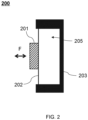
- FIG. 2 is a schematic structural diagram illustrating an impedance device according to some embodiments of the present disclosure.
- an impedance device 200 may include a mass part 201, an elastic part 202, and a fixing part 203.
- the mass part 201 is connected to the fixing part 203 through the elastic part 202, and the mass part 201 may vibrate relative to the fixing part 203.
- the fixing part 203 may be a cuboid, a cylinder, a terraced structure, a triangular prism, a spherical or hemispherical structure, or other regular or irregular structures.
- the fixing part 203 may be a hollow structure with an open exposure (also referred to as an opening), and the elastic part 202 is located at the opening of the fixing part 203 to form a cavity 205 with the fixing part 203.
- the cavity 205 may be a closed cavity.
- the elastic part 202 may be a membranous structure, the shape and a size of the membranous structure are approximately the same as the shape and the size of the opening of the fixing part 203, and the elastic part 202 may connect with a side wall of the fixing part 203 through its peripheral side to form the closed cavity 205.
- the size of the membranous structure is greater than or equal to the size of the opening of the fixing part 203, and the membranous structure is located at one end of the fixing part 203 with the opening to cover the opening.
- the material of the membranous structure may be an elastic silica gel, a rubber, etc.
- the cavity 205 may further communicate with the outside world.
- the membranous structure includes a hole (not shown in FIG. 2 ), and the cavity 205 communicates with the outside through the hole.
- the shape and the size of the membranous structure do not match the shape and the size of the opening of the fixing part 203, and a peripheral part of the membranous structure is connected to the side wall of the fixing part 203.
- the elastic part 202 may further be a reed structure, which is connected to the side wall of the fixing part 203 through its peripheral side, and the reed structure may completely or partially cover the opening area.
- the material of the reed structure may include a metal (e.g., a stainless steel, a beryllium copper, etc.), a plastic, etc.
- a gas in the cavity 205 may further provide the elasticity and the damping.
- the gas in the cavity 205 has the features of compressibility and expandability.
- the elastic part 202 deforms to cause the volume of the cavity 205 to become smaller, the pressure inside the cavity 205 increases, and the gas inside the cavity 205 generates a force on the elastic part 202 and the mass part 201, and the direction of the force is opposite to the movement direction of the mass part 201.
- the mass part 201 moves away from the fixing part 203, it is opposite to the above situation.
- the gas in the cavity 205 may provide the elasticity.
- the cavity 205 may further be filled with a liquid with a certain viscosity, such as one or more of a magnetic fluid, a water, an oily organic matter, etc., or the cavity 205 may be filled with both the liquid and the gas.
- the mass part 201 vibrates relative to the fixing part 203 under the elastic action of the elastic part 202, and the vibration has different frequency responses under different frequencies.
- the vibration produces a resonance peak within a first specified frequency range.
- the first specific frequency band range may be from 20 Hz to 300 Hz. In some embodiments, the first specific frequency band range may be 40 Hz-60 Hz.
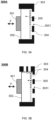
- FIG. 3A is a schematic structural diagram illustrating an impedance device according to some embodiments of the present disclosure.
- an impedance device 300A may include a mass part 301, an elastic part 302, and a fixing part 303.
- the mass part 301 may be connected to the fixing part 303 through the elastic part 302, and the mass part 301 may vibrate relative to the fixing part 303.
- the fixing part 303 may be a hollow structure with an opening, and the elastic part 302 is located at the opening of the fixing part 303 to form a cavity 305 with the fixing part 303.
- one or more holes 3031 are set on the side wall of the fixing part 303 opposite to the mass part 301 to communicate the air inside the cavity 305 with the air outside the cavity 305.
- the impedance device 300A may further include an acoustic gauze 304 covering the one or more holes 3031, and the acoustic gauze 304 enables the air inside the cavity 305 to communicate with the air outside the cavity 305. Under an action of an external force (arrow F shown in FIG. 3A ), the mass part 301 vibrates relative to the fixing part 303.
- the elastic part 302 When the mass part 301 generates a movement displacement relative to the fixing part 303 and acts on the elastic part 302, the elastic part 302 generates an elastic deformation, so that the pressure inside the cavity 305 increases, and the air inside the cavity 305 leaks to the external environment through the one or more holes 3031.
- the air passes through the acoustic gauze 304 the airflow is subject to a viscous action, thus providing a damping for the movement of the mass part 301.
- the cavity 305 and the air inside it, as well as the acoustic gauze 304 may be regarded as the damping structure of the impedance device 300A, so as to provide the damping for the movement of the mass part 301.
- the damping of the impedance device 300A may be adjusted by adjusting sizes of the one or more holes 3031, a volume of the cavity, or an acoustic range of the acoustic gauze 304.
- a total area of the one or more holes 3031 occupies 10% to 90% of the area of side wall of the fixing part 303 where the one or more holes 3031 locate, the volume of the cavity is not more than 1000 cm 3 , and the acoustic resistance of the acoustic gauze 304 may be in a range of 500 Rayl to 1600 Rayl.
- the total area of the one or more holes 3031 occupies 20% to 80% of the area of side wall of the fixing part 303 where the one or more holes 3031 locate, the volume of the cavity is not more than 800 cm 3 , and the acoustic resistance of the acoustic gauze 304 may be in a range of 600 Rayl to 1400 Rayl.
- the total area of the one or more holes 3031 occupies 30% to 60% of the area of side wall of the fixing part 303 where the one or more holes 3031 locate, the volume of the cavity is not more than 600 cm 3 , and the acoustic resistance of the acoustic gauze 304 may be in a range of 800 Rayl to 1200 Rayl.
- the elastic part 302 may simultaneously provide an elastic support and damping functions.
- the elastic part 302 may be other structures (e.g., a membranous structure, a rod structure, or a block-like structure made of a flexible material) of any shape capable of carrying the mass part 301 and connecting the fixing part 303.
- the flexible material may include but not limited to any one or more of a silicone, a rubber, polyvinyl alcohol (PVA), polyester (PET), polyimide (PI), polyethylene naphthalate (PEN), a textile material, etc. Under the action of an external force (arrow F shown in FIG. 3A ), the mass part 301 vibrates relative to the fixing part 303.
- the elastic part 302 When the mass part 301 generates a movement displacement relative to the fixing part 303 and acts on the elastic part 302, the elastic part 302 generates an elastic deformation, so that an internal friction of the elastic part 302 generates a heat energy, thereby providing the damping for the movement of the mass part 301.
- the elastic coefficient of the elastic part 302 in the vibration direction in which the mass part 301 vibrates relative to the fixing part 303 may be in a range of 600N/m to 5000N/m.
- the elastic coefficient of the elastic part 302 in the vibration direction in which the mass part 301 vibrates relative to the fixing part 303 may be in a range of 700N/m to 3500N/m.
- the elastic coefficient of the elastic part 302 in the vibration direction in which the mass part 301 vibrates relative to the fixing part 303 may be in a range of 900 N/m to 1700 N/m.
- the elastic part 302 when the elastic part 302 is a structure made of the flexible material, the elastic part 302 itself may provide the elasticity and the damping effect at the same time, and the side wall opposite to the mass part 301 of the fixing part 303 may not be additionally provided with the damping structure (e.g., the one or more holes 3031 and the acoustic gauze 304), or may further be provided with the damping structure at the same time. At this time, the elastic part 302 and the damping structure together provide the damping for the movement of the mass part 301.
- the elastic part 302 made of the flexible material may further be applied to the impedance device provided in other embodiments of the present disclosure, for example, the impedance device 300B shown in FIG.
- the impedance device 300A is only for illustration and description, and does not limit the scope of application of the present disclosure.
- various modifications and changes can be made to the impedance device 300A.
- the one or more holes 3031 and the acoustic gauze 304 may further be located at the side wall, or, in the impedance device 300B shown in FIG. 3B , the one or more holes 3031 and the acoustic gauze 304 may further be provided on the side wall of the fixing part 303 connecting the elastic part 302, and on the side wall of the fixing part 303 opposite to the mass part 301.
- Such modifications and changes remain within the scope of the present disclosure.
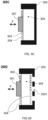
- FIG. 3C is a schematic structural diagram of an impedance device according to some other embodiments of the present disclosure.
- An impedance device 300C shown in FIG. 3C is substantially the same as the impedance device 300A shown in FIG. 3A , a main difference being that the cavity 305 of the impedance device 300C communicates with the outside through the elastic part 302.
- the elastic part 302 may be a reed structure, and the reed structure covers an opening of the fixing part 303 and forms a cavity 305.
- the reed structure may include a hollow area (not shown in FIG. 3C ) that enables air inside the cavity 305 to communicate with the air outside the cavity 305.
- the hollow area may be covered with the acoustic gauze 304, which enables the air inside the cavity 305 to communicate with the air outside the cavity 305 and provides a damping.
- the elastic part 302 may be a membranous structure, one or more holes are set on the membranous structure, and the one or more holes enable the air inside the cavity 305 to communicate with the air outside the cavity 305.
- the one or more holes may be covered with the acoustic gauze 304, and the acoustic gauze 304 enables the air inside the cavity 305 to communicate with the air outside the cavity 305 and provides the damping.
- FIG. 3D is a schematic structural diagram illustrating an impedance device according to some other embodiments of the present disclosure.
- An impedance device 300D shown in FIG. 3D is similar in structure to the impedance device 300A shown in FIG. 3A , the impedance device 300B shown in FIG. 3B , and the impedance device 300C shown in FIG. 3C .
- the fixing part 303 and the elastic part 302 are provided with damping structures.
- one or more holes 3031 are provided on a side wall of the fixing part 303 opposite to the mass part 301 to communicate air inside the cavity 305 from the air outside the cavity 305.
- the impedance device 300 D may further include an acoustic gauze 304 covering the one or more holes 3031, which enables the air inside the cavity 305 to communicate with the air outside the cavity 305.
- the elastic part 302 has a hollow area or a hole, and the hollow area or the hole is covered with the acoustic gauze 304, the acoustic gauze 304 enables the air inside the cavity 305 to communicate with the air outside the cavity 305, and provides a damping.
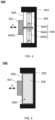
- FIG. 4 is a schematic structural diagram illustrating an impedance device according to some embodiments of the present disclosure.
- an impedance device 400 may include a mass part 401, an elastic part 402, and a fixing part 403.
- the mass part 401 is connected to the fixing part 403 through the elastic part 402, and the mass part 401 may vibrate relative to the fixing part 403.
- the fixing part 403 may be a structure with a groove 405, and the elastic part 402 is located at the groove 405 of the fixing part 403 and connected to the fixing part 403 through the elastic part 402.
- the elastic part 402 may be a membranous structure, a rod-like structure, a sheet-like structure, etc.
- the impedance device 400 may further include a magnetic circuit structure, and the magnetic circuit structure may be located between the elastic part 402 and the fixing part 403.
- the magnetic circuit structure may include a first magnet 4041 and a second magnet 4042 arranged at intervals in the groove 405, one pole of the first magnet 4041 and one pole of the second magnet 4042 are opposite to each other to form a magnetic gap 4043.
- the other pole of the first magnet 4041 and the other pole of the second magnet 4042 are connected to the fixing part 403.
- the impedance device 400 may further include a metal sheet 4044, one end of the metal sheet 4044 is connected to the mass part 401 or the elastic part 402, and the other end of the metal sheet 4044 extends to a side away from the mass part 401 or the elastic part 402, and extends into the magnetic gap 4043.
- the mass part 401 vibrates relative to the fixing part 403.
- the mass part 401 generates a movement displacement relative to the fixing part 403
- drives the metal sheet 4044 to perform a movement to cut magnetic lines in the magnetic gap 4043, so that the metal sheet 4044 generates eddy currents.
- the metal sheet 4044 produces an action force opposite to the displacement direction of the mass part 401 when it is moving to cut the magnetic lines.
- the action force acts on the mass part 401 to provide a damping for the movement of the mass part 401.
- the magnetic circuit structure and the metal sheet 4044 are the damping structure 404 of the impedance device 400, providing the damping for the movement of the mass part 401.
- a damping value provided by the damping structure 404 may be within a specific range (e.g., 1-4).
- the metal sheet 4044 may be made of a high-conductivity metal.
- the material of the metal sheet 4044 may include, but not limited to, a copper, an aluminum, a silver, a gold, a platinum, etc.
- the metal sheet 4044 may further be replaced with a structure made of other non-metallic materials with conductive lines, such as one or more of graphite, semiconductor materials (such as a selenium, a silicon, a germanium, a silicon carbide, a Gallium arsenide, etc.) etc.
- the metal sheet 4044 may further be replaced by a structure made of a mixture of the non-metallic materials and the metal materials.
- the projection area of the metal sheet 4044 on the magnetic circuit structure (e.g., a pole of the first magnet 4041 opposite to the second magnet 4042) is in a range of 25 mm 2 ⁇ 400 mm 2
- the magnetic flux of the magnetic circuit structure is in a range of 0.2 T ⁇ 1.8 T
- a resistivity of the metal sheet 1044 is in a range of 0.8 ⁇ 10 -8 ⁇ m to 2.0 ⁇ 10 -8 ⁇ m.
- the projection area of the metal sheet 4044 on the magnetic circuit structure is in a range of 50 mm 2 ⁇ 200 mm 2
- the magnetic flux of the magnetic circuit structure is in a range of 0.8 T ⁇ 1.5 T
- the resistivity of the metal sheet 1044 is in a range of 1.2 ⁇ 10 -8 ⁇ m to 2.0 ⁇ 10 -8 ⁇ m.
- the impedance device 400 is only for illustration and description, and does not limit the scope of application of the present disclosure.
- various modifications and changes can be made to the impedance device 400 under the guidance of the present disclosure.
- the magnets of the magnetic circuit structure are not limited to the above-mentioned first magnet 4041 and second magnet 4042, and may also include other magnets, meanwhile, such modifications and changes remain within the scope of the present disclosure.
- the impedance device 400 may further be provided with the damping structures shown in FIGS. 3A-3D at the same time.
- FIG. 5 is a schematic structural diagram illustrating an impedance device according to some embodiments of the present disclosure.
- an overall structure of an impedance device 500 shown in FIG. 5 is substantially the same as that of the impedance device 200 shown in FIG. 2 .
- a mass part 501, an elastic part 502, a fixing part 503, and a cavity 505 are respectively similar to the mass part 201, the elastic part 202, the fixing part 203, and the cavity 205 in FIG. 2 , which will not be repeated here.
- the cavity 505 is filled with a flexible structure 504, and the flexible structure 504 is in contact with the elastic part 502 and the fixing part 503, respectively.
- the flexible structure 504 has an elasticity. When the mass part 501 generates a movement displacement, the elastic part 502 undergoes an elastic deformation, and the elastic part 502 acts on the flexible structure 504 at the same time.
- the flexible structure 504 has a certain elasticity, which can absorb a part of the vibration of the mass part 501 and play a role of a damping.
- a material of the flexible structure may include, but not limited to, a silicone, a rubber, a polyvinyl alcohol (PVA), a polyester (PET), a polyimide (PI), a polyethylene naphthalate (PEN), or a textile material.
- the flexible structure 504 has a porous structure, such as a compressed foam. The elastic part 502 undergoes the elastic deformation and acts on the flexible structure 504, an airflow in the cavity 505 spreads in the porous pores of the flexible structure 504, and the airflow receives a viscous effect, thereby providing the damping for the movement of the mass part 501. It should be noted that the flexible structure here is the damping structure of the impedance device 500.
- a hardness of the flexible structure 504 may be in a range of 5 degrees to 45 degrees, and a density of the flexible structure 504 may be in a range of 40 kg/m3 to 120 kg/m3.
- the hardness of the flexible structure 504 may be in a range of 12 degrees to 35 degrees, and the density of the flexible structure 504 may be in a range of 60 kg/m3 to 100 kg/m3.
- Fig. 6 is a schematic structural diagram of an impedance device provided according to some embodiments of the present disclosure.
- an overall structure of the impedance device 600 shown in FIG. 6 is substantially the same as that of the impedance device 500 shown in FIG. 5 .
- the structures of a mass part 601, an elastic part 602, and a fixing part 603 are similar to that of the mass part 501, an elastic part 502, and a fixing part 503, respectively.
- a difference between them lies that the flexible structure 604 fills a part of the cavity 605, and an area inside the cavity 605 that is not filled by the flexible structure 604 is air.
- the damping structures shown in FIGS. 3A-3D may further be applied to the impedance device 600 shown in FIG.
- a total damping of the impedance device 600 is an equivalent damping.
- the equivalent damping may be in a range of 1-4. More preferably, the damping range of the equivalent damping may be in a range of 1 to 3. More preferably, the damping range of the equivalent damping may be in a range of 1 to 2.
- FIG. 7 is a schematic structural diagram illustrating an impedance device according to some embodiments of the present disclosure.
- An overall structure of the impedance device 700 shown in FIG. 7 is substantially the same as that of the impedance device 200 shown in FIG. 2 .
- the structures of a mass part 701, an elastic part 702, and a fixing part 703 are similar to that of the mass part 201, an elastic part 202, and a fixing part 203, respectively, which will not be repeated here.
- a difference between the impedance device 700 and the impedance device 200 is that the impedance device 700 shown in FIG. 7 may include a damping structure 704 located on a side of the mass part 701 away from the elastic part 702 and is spaced apart from the mass part 701.
- the damping structure 704 may be made of a flexible material.
- exemplary flexible material may include but not limited to a silicone, a rubber, a polyvinyl alcohol (PVA), a polyester (PET), a polyimide (PI), a polyethylene naphthalate (PEN), a textile material, etc.
- PVA polyvinyl alcohol
- PET polyester
- PI polyimide
- PEN polyethylene naphthalate
- the damping structure 704 has porous pores, e.g., a compressed foam.
- the vibration unit 706 may be located between the damping structure 704 and the mass part 701, the damping structure 704 may be directly fixedly connected to the fixing part 703, or the damping structure 704 may be fixed by a fastener (e.g., a support rod), so that the vibration unit 706 is fixed between the damping structure 704 and the mass part 701.
- a fastener e.g., a support rod
- the damping structure 704 may absorb a vibration energy of the vibration unit 706 to provide a damping effect.
- a single part may function as different parts at the same time.
- a single part may function as both the mass part and the elastic part.
- the elastic part is a reed structure
- a mass of the reed structure may be relatively great.
- the reed structure not only plays the role of providing elasticity for the elastic part, but also plays the role of providing the mass.
- a sum of the mass of the reed structure (e.g., 1/3 of the mass of the reed structure) and the mass of the mass part may be used to determine the mass value provided by the parts in the impedance device, and then more accurately determine the mass value provided by the parts in the impedance device.
- a single part of the impedance device may function as both the elastic part and the damping structure.
- the air inside the cavity also provides an elasticity.
- a single part of the impedance device may function both as the mass part and as the damping structure.
- the vibration unit pushes the mass part to move and displace, and at the same time the mass part is squeezed, and the internal porous pores may further play the damping effect.
- a single part of the impedance device may simultaneously function as the mass part, the elastic part, and the damping structure.
- the silicon rubber diaphragm provides the elastic force on the one hand, and an internal friction may further play a damping effect when the diaphragm moves.
- a part of the mass of the diaphragm also needs to be included in an additional mass pf the mass part.
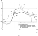
- FIG. 8 illustrates a frequency response curve of a vibration of a vibration unit according to some embodiments of the present disclosure.
- an abscissa represents a frequency (Hz)
- an ordinate represents a frequency response (dB) of the vibration unit.
- a frequency response curve 810 (the curve corresponding to a "real human head wearing vibration unit” shown in FIG. 8 ) represents a measured vibration frequency response curve after the vibration unit is coupled with an actual face tragus area.
- a frequency response curve 820 (the curve corresponding to a "no-impedance device” shown in FIG. 8 ) represents a measured frequency response curve of the vibration unit in a suspension state.
- a frequency response curve 830 (the curve corresponding to " impedance device with mass part and elastic part” shown in FIG. 8 ) represents a measured frequency response curve after the impedance device without a damping structure is coupled with the vibration unit.
- a frequency response curve 840 (the curve corresponding to "impedance device with mass part, elastic part, and damping structure" shown in FIG. 8 ) represents a measured frequency response curve after the impedance device with a damping structure is coupled with the vibration unit.
- FIG. 8 combining the frequency response curve 810 and the frequency response curve 820, it can be seen that there is indeed a significant difference between the frequency response curve of the vibration unit in a suspension state and the frequency response curve after the vibration unit is coupled with the actual face tragus area.
- the frequency response after the impedance device without a damping structure is coupled with the vibration unit is basically consistent with the frequency response after the vibration unit is coupled with the actual face tragus area.
- the difference between the frequency response after the impedance device with a damping structure is coupled with the vibration unit and the frequency response after the vibration unit is coupled with the actual face tragus area is small.
- the frequency response curves 810 and 840 are substantially identical. It can be seen from this that the impedance device described in the present disclosure basically matches the mechanical impedance of the actual human face, and can reflect the mechanical features of the actual human face.
- the impedance device may be adjusted by adjusting the mass of the impedance device, the elastic coefficient of the elastic part, or the damping of the damping structure, so that the mechanical impedance provided by the impedance device is approximately consistent with the mechanical impedance near the tragus region of the head.
- the frequency response curve of the vibration unit when the vibration unit is worn near the tragus region of the head has a resonance peak 811 in a first specific frequency band range (e.g., 20 Hz-300 Hz), that is, a vibration force level of the vibration unit when the vibration unit is worn near the tragus region of the head has a maximum value (also called a peak) within the first specific frequency band range.
- the vibration force level of the vibration unit when the vibration unit is worn near the tragus region of the head decreases as the frequency increases.
- the vibration force level of the vibration unit is in a range of -90 dB to -70 dB, and a difference between the vibration force level of the resonance peak 811 of the vibration unit and the vibration force level within the range greater than the resonance frequency corresponding to the resonance peak 811 is in a range of 10 dB to 20 dB.
- the mechanical impedance frequency response curve near the tragus area of the human head has a trough in a second specific frequency band range (e.g., 50 Hz-500 Hz), that is, the mechanical impedance near the tragus region of the head has a minimum value (also called a trough value) in a specific frequency band range.
- a second specific frequency band range e.g. 50 Hz-500 Hz
- the mechanical impedance near the tragus region of the head has a minimum value (also called a trough value) in a specific frequency band range.
- the frequency corresponding to the trough is smaller than the frequency corresponding to the resonance peak.
- the second specific frequency band range is not limited to the above-mentioned 50 Hz-500 Hz. In some embodiments, the second specific frequency band range may also be other frequency ranges such as 60 Hz-400 Hz, 70 Hz-300 Hz, or 80 Hz-200 Hz, or any frequency value in this range.
- the damping of the impedance device can be adjusted so that the features of the mechanical impedance provided by the impedance device are consistent or approximately consistent with the features of the mechanical impedance near the tragus region of the head.
- a trough value of a mechanical impedance provided by the impedance device is used as an example for illustration.
- a damping of the damping structure may be adjusted to a range of 1 to 4, so that the trough value of the mechanical impedance of the impedance device is in a range of 0 dB to 15 dB.
- the damping of the damping structure may be adjusted to be in a rage of 1.5 to 3.9, so that the trough value of the mechanical impedance of the impedance device is in a range of 2 dB to 13 dB. Further preferably, the damping of the damping structure may be adjusted to be in a range of 2 to 3.7, so that the trough value of the mechanical impedance of the impedance device is in a range of 3 dB to 12 dB. More preferably, the damping of the damping structure may be adjusted to be in a range of 2.4 to 3.2, so that the trough value of the mechanical impedance of the impedance device is in a range of 6 dB to 10 dB.
- the mass of the mass part and the elastic coefficient of the elastic part may be adjusted so that the frequency corresponding to the trough value is within a specific frequency band range.
- the range of the mass of the mass part may be adjusted to be in a range of 0.5 g ⁇ 5 g, and the elastic coefficient of the elastic part may be in a range of 600 N/m ⁇ 5000 N/m, so that the trough value of the impedance device may be in a range of 50 Hz-500 Hz.
- the mass of the mass part may be adjusted to be in a range of 0.8 g to 4.5 g, and the elastic coefficient of the elastic part may be in a range of 700 N/m to 3500 N/m, so that the trough value of the impedance device may be in a range of 60 Hz to 320 Hz. More preferably, the mass of the mass part may be adjusted to be in a range of 1 g to 3.6 g, and the elastic coefficient of the elastic part may be in a range of 900 N/m to 1700 N/m, so that the trough value of the impedance device may be in a range of 80 Hz to 200 Hz.
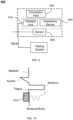
- FIG. 9 is an exemplary frame diagram illustrating a system for simulating an impact of a head on a vibration of a vibration unit according to some embodiments of the present disclosure.
- a system 900 may include a vibration unit 910, an impedance device 920, a connection part 930, and a sensor 940.
- the vibration unit 910 may be configured to provide a vibration signal. In some embodiments, the vibration unit 910 may convert a signal containing audio information into a vibration signal. In some embodiments, the audio information may include video and audio files in a specific data format, or data or files that can be converted into audio in a specific way, and the signal containing the audio information may come from a storage component that communicates with or is connected to the vibration unit 910. In some embodiments, the signal containing audio information may include an electrical signal, an optical signal, a magnetic signal, a mechanical signal, etc., or any combination thereof.
- the vibration unit 910 may obtain the signal containing audio information in a variety of different ways, including but not limited to a wired or wireless acquisition, a real-time acquisition, or a delayed acquisition.
- the vibration unit 910 may receive the electrical signal containing audio information in a wired or wireless manner, or may directly obtain data from a storage medium to generate the signal.
- the vibration unit 910 may realize the conversion from the signal containing the audio information into a mechanical vibration.
- the conversion process may include a coexistence and conversion of various types of energy.
- the electrical signal may be directly converted into the mechanical vibration and produces sound.
- the audio information may be included in the optical signal, and the process of converting the optical signal into the vibration signal may be implemented through a transducer.
- Other types of energy that can coexist and convert during the working process of the transducer include a thermal energy, a magnetic field energy, etc.
- an energy conversion mode of the transducer may include a moving coil, an electrostatic, a piezoelectric, a moving iron, a pneumatic, an electromagnetic, etc., or any combination thereof.
- the impedance device 920 may contact the vibration unit 910 and provide a mechanical impedance to the vibration unit 910. In some embodiments, there is a certain pressure between the impedance device 920 and the vibration unit 910.
- the mechanical impedance provided by the impedance device 920 may simulate the impedance of the head relative to the vibration unit 910 in an actual use. A vibration state of the vibration unit 910 provided with the mechanical impedance is consistent or nearly consistent with vibration features when it is actually used on the head, so that the system may simulate the impact of the mechanical impedance of the head on the vibration state of the vibration unit 910 when the vibration unit 910 is coupled with head vibration. Descriptions regarding the impedance device may be found in FIGs. 1-7 , which are not repeated here.
- connection part 930 may be configured to couple the vibration unit 910 with the impedance device 920.
- the connection part 930 may provide a pressure of 0.05 N-3.5 N for the vibration unit 910 and the impedance device 920.
- the connection part 930 may provide the pressure of 0.1N-3N for the vibration unit 910 and the impedance device 920.
- the connection part 930 may provide the pressure of 0.3 N-2.5 N for the vibration unit 910 and the impedance device 920.
- the connection part 930 may provide the pressure of 0.5 N-2 N for the vibration unit 910 and the impedance device 920.
- connection part 930 may provide the pressure of 0.8 N-1.8 N for the vibration unit 910 and the impedance device 920.
- the connection part 930 may provide the pressure of 1 N-1.5 N for the vibration unit 910 and the impedance device 920.
- the connecting part 930 may be connected with the vibration unit 910 and apply the pressure to the vibration unit 910, so that the vibration unit 910 may be coupled with the impedance device 920, such as a support frame, etc.
- the connection part 930 may be connected to the vibration unit 910 and fixedly contact other fixed structures. For example, the connection part 930 may bind the vibration unit 910 to other fixed structures.
- connection part 930 may be integrally formed with the vibration unit 910, and may be fixedly contact other fixed structures such as an ear hook structure integrally formed with an earphone, an ear clamping structure integrally formed with a hearing aid, a glasses frame structure integrally formed with an audio glasses, etc.
- connection part 930 may be made of plastic or metal with certain hardness and shape.
- the material of the connection part 930 may further be silicone, rubber, fabric, etc. with certain elasticity.
- the material of the connection part 930 may further be foam, which provides the damping for the movement of the vibration unit 910.
- the impedance device 920 when the connection part 930 provides the vibration unit 910 and the impedance device 920 with a pressure of 0.05N ⁇ 3.5N, the impedance device 920 provides the vibration unit 910 with a mechanical impedance in a range of 6 dB-50 dB.
- the mechanical impedance in the range of 6 dB ⁇ 50 dB simulates the actual impedance fed back to the vibration unit 910 near the tragus area during the actual use, so that the vibration impact of the mechanical impedance on the vibration unit 910 when the vibration unit 910 is coupled with the impedance device 920 may simulate the vibration impact of a head actual impedance when the vibration unit 910 is coupled with the head. In this way, it is convenient for a testing or a calibration device of related products in development and production.
- an area of the coupling area between the impedance device 920 and the vibration unit 910 may be in a range of 0.25 cm 2 to 4 cm 2 . In some embodiments, the area of the coupling area between the impedance device 920 and the vibration unit 910 may be in a range of 1 cm 2 to 3.6 cm 2 . In some embodiments, the area of the coupling area between the impedance device 920 and the vibration unit 910 may be in a range of 1 cm 2 to 3.6 cm 2 . In some embodiments, the area of the coupling area between the impedance device 920 and the vibration unit 910 may be in a range of 1 cm 2 to 3.6 cm 2 .
- the area of the coupling area between the impedance device 920 and the vibration unit 910 is not limited to the above-mentioned range, and may further be in other ranges.
- the area of the coupling area may be greater than 4 cm 2 or smaller than 0.25 cm 2 , and the specific area of the coupling area may be adaptively adjusted according to a size of the vibration unit 910.
- the senor 940 may be configured to collect parameter information of the vibration unit 910 during the vibration. In some embodiments, the sensor 940 may be further configured to collect the parameter information during a coupling vibration process of the vibration unit 910 and the impedance device 920. In some embodiments, the parameter information in the vibration process may be configured to represent the vibration impact of the vibration unit 910. In some embodiments, the parameter information in the vibration process may include vibration feature data, and the vibration feature data may include but not limited to one or more of a vibration displacement, a vibration velocity, a vibration acceleration, etc.
- the parameter information in the vibration process may include air conduction acoustic feature data generated by the vibration, and the air conduction acoustic feature data may include but not limited to a sound pressure level or a frequency response of the air conduction sound.
- the sensor 940 may be located at the vibration unit 910.
- the sensor 940 may be directly installed on a surface or inside of the vibration unit 910.
- the sensor 940 may be indirectly connected to the vibration unit 910.
- the sensor 940 may be installed on the surface or inside of the impedance device 920.
- the sensor 940 may be installed on the mass part of the impedance device 920.
- the sensor 940 may further be located on the connection part 930.
- the type and/or form of the sensor 940 may not be limited.
- the sensor 940 may be a non-contact laser sensor (e.g., a vibrometer, a Doppler tester) or an air conduction speaker that can obtain a vibration acceleration (a velocity or displacement), or it may be various contact acceleration sensors, bone conduction sensors, piezoelectric sensors, MEMS sensors, etc.
- the system may further include a test system, and the test system may be connected to at least one sensor 940 to collect and/or process a detection signal of the at least one sensor 940.
- the testing system may be connected to the vibration unit 910 to provide a driving signal to the vibration unit 910 to drive the vibration unit 910 to generate a mechanical vibration signal.
- the test system is connected with the at least one sensor 940 and the vibration unit 910, drives the vibration unit 910 to generate the mechanical vibration signal, and collects and processes the signal collected by the at least one sensor 940.
- the system for simulating the impact of the head on the vibration of the vibration unit 910 shown in FIG. 9 is only for example and description, and does not limit the scope of application of the present disclosure.
- various corrections and changes may be made to the system under the guidance of the present disclosure.
- a plurality of sensors 940 of different types or forms may be set to monitor more complete parameter information.
- the connection part 930 may be omitted and the vibration unit 910 and the impedance device 920 may be directly coupled through a magnetic attraction or adhesion, these modifications and changes are still within the scope of the present disclosure.
- FIG. 10 is a diagram illustrating a position of a head coupling area simulated by an impedance device according to some embodiments of the present disclosure.
- the vibration unit 910 when the vibration unit 910 is coupled to the head, the vibration unit 910 is coupled to the front side of a tragus (near the tragus area) of a human body along a cross section viewed from the top of the head.
- the vibration unit 910 directly transmits a vibration signal to an auditory ossicles of a middle ear and a cochlea of an inner ear, avoiding the tympanic membrane by mainly vibrating a temporal bone in front of the tragus.
- the vibration of the vibration unit 910 may further drive a surrounding air to vibrate to generate a part of an air conduction sound, which is transmitted to the eardrum through an external auditory canal.
- the impedance device shown in some embodiments of the present disclosure is configured to simulate an actual impedance generated near the tragus area where the vibration unit 910 is coupled with the tragus area, and the system for simulating the impact of the head on the vibration of the vibration unit 910 is configured to simulate a vibration impact of an actual impedance near the tragus area on the vibration of the vibration unit 910 when the vibration unit 910 vibrates near the coupling tragus area.
- the coupling between the vibration unit 910 and a vicinity of the tragus area may meet application scenarios of most bone conduction earphones, and may further meet the application scenarios of some hearing aids. Therefore, the system for simulating the impact of the head on the vibration of the vibration unit 910 may objectively measure the vibration impact of the vibration unit 910, and simulate the actual frequency response of the vibration unit 910 when the vibration unit 910 vibrates near the coupling tragus area, which may be used as a testing or calibration device of related products in development and production.
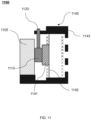
- FIG. 11 is a schematic structural diagram illustrating a system for simulating an impact of a head on a vibration of a vibration unit according to some embodiments of the present disclosure.
- a mass part 1141, an elastic part 1142, and a fixing part 1143 in FIG. 11 are similar to the mass part 301, the elastic part 302, and the fixing part 303 in FIG. 3D , which will not be repeated here.
- a system 1100 may include a vibration unit 1110, a connection part 1120, and an impedance device 1140.
- the connection part 1120 may be fixedly arranged at the fixing part 1143 of the impedance device 1140, and one end of the connection part 1120 is connected to the vibration unit 1110.
- connection part 1120 couples the vibration unit 1110 to the mass part 1141 of the impedance device 1140.
- a force applied by the connection part 1120 on the vibration unit 1110 may provide a pressure for coupling the vibration unit 1110 and the impedance device 1140.
- the connection part 1120 may be an independent structure relative to the impedance device.
- the connection part 1120 may be located on a side of the mass part 1141 away from the elastic part 1142, and be spaced apart from the mass part 1141.
- the vibration unit 1110 may be located between the connection part 1120 and the mass part 1141.
- the pressure for coupling the vibration unit 1110 and the impedance device 1140 may be adjusted by adjusting the position of the connection part 1120.
- the system 1100 may further include a damping structure 1105, the damping structure 1105 is located on the side of the mass part 1141 away from the elastic part 1142, and is spaced apart from the mass part 1141.
- the vibration unit 1110 is located between the damping structure 1105 and the mass part 1141.
- a material of the damping structure 1105 has porous pores, such as compressed foam, to provide damping to the movement of the vibration unit 1110, thereby simulating a scene where the vibration unit 1110 is worn near a tragus of a human body.
- damping structure 1105 or the impedance device 1140 shown in FIG. 11 may be replaced by the impedance device 200 shown in FIG. 2 , the impedance device 300A shown in FIG. 3A , the impedance device 300B shown in FIG. 3B , the impedance device 300C shown in FIG. 3C , the impedance device 400 shown in FIG. 4 , the impedance device 500 shown in FIG. 5 , the impedance device 600 shown in FIG. 6 , or the impedance device 700 shown in FIG. 7 .
- FIG. 12 is a schematic structural diagram illustrating a system for simulating an impact of a head on a vibration of a vibration unit according to some embodiments of the present disclosure.
- a system 1200 may include an earphone and an impedance device.
- the earphone may include a vibration unit 1210 (e.g., a bone conduction speaker) and a connection part 1220.
- the connection part 1220 may be an ear hook structure, and the ear hook structure may surround on the head of the user, and fix the vibration unit 1210 near the tragus area of the user.
- the impedance device may include a mass part 1241, an elastic part 1242, and a fixing part 1243.
- the mass part 1241 is connected to the fixing part 1243 through the elastic part 1242.
- the vibration unit 1210 drives the mass part 1241 to vibrate relative to the fixing part 1243 together.
- the impedance device in FIG. 12 may be replaced by the impedance device 200 shown in FIG. 2 , the impedance device 300A shown in FIG. 3A , the impedance device 300B shown in FIG. 3B , the impedance device 300C shown in FIG. 3C , the impedance device 300D shown in FIG. 3D , the impedance device 400 shown in FIG. 4 , the impedance device 500 shown in FIG. 5 , the impedance device 600 shown in FIG. 6 , or the impedance device 700 shown in FIG. 7 .
- FIG. 1-FIG. 12 are only used for exemplary descriptions, and are not limited thereto.
- various changes and modifications can be made based under the teaching of the present disclosure.
- Different embodiments may have different beneficial effects, and in different embodiments, the possible beneficial effects may be any one or a combination of several of the above, or any other possible beneficial effects.
- the present disclosure uses specific words to describe the embodiments of the present disclosure.
- “one embodiment”, “an embodiment”, and/or “some embodiments” refer to a certain feature, structure or characteristic related to at least one embodiment of the present disclosure. Therefore, it should be emphasized and noted that two or more references to “an embodiment” or “one embodiment” or “an alternative embodiment” in different places in the present disclosure do not necessarily refer to the same embodiment.
- certain features, structures, or characteristics of one or more embodiments of the present disclosure may be properly combined.
- numbers describing the quantity of parts and attributes are used. It should be understood that such numbers used in the description of the embodiments use the modifiers "about”, “approximately” or “substantially” in some examples. Unless otherwise stated, the “about”, “approximately” or “substantially” indicates that the figure enables for a variation of ⁇ 20%. Accordingly, in some embodiments, the numerical parameters used in the present disclosure and claims are approximations that can vary depending upon the desired features of individual embodiments. In some embodiments, the numerical parameters should consider the specified significant digits and adopt the general digit reservation method. Although the numerical ranges and parameters used in some embodiments of the present disclosure to confirm the breadth of the scope are approximate values, in specific embodiments, such numerical values are set as precisely as practicable.
Landscapes
- Engineering & Computer Science (AREA)
- Physics & Mathematics (AREA)
- Acoustics & Sound (AREA)
- Signal Processing (AREA)
- Otolaryngology (AREA)
- Health & Medical Sciences (AREA)
- General Health & Medical Sciences (AREA)
- Neurosurgery (AREA)
- Manufacturing & Machinery (AREA)
- General Physics & Mathematics (AREA)
- Details Of Audible-Bandwidth Transducers (AREA)
- Vibration Prevention Devices (AREA)
- Apparatuses For Generation Of Mechanical Vibrations (AREA)
- Headphones And Earphones (AREA)
- Circuit For Audible Band Transducer (AREA)
- Percussion Or Vibration Massage (AREA)
Applications Claiming Priority (3)
| Application Number | Priority Date | Filing Date | Title |
|---|---|---|---|
| CN202110033059 | 2021-01-11 | ||
| PCT/CN2021/141078 WO2022148249A1 (zh) | 2021-01-11 | 2021-12-24 | 一种阻抗装置及模拟头部对振动单元振动影响的系统 |
| PCT/CN2022/128431 WO2023116200A1 (zh) | 2021-01-11 | 2022-10-28 | 一种阻抗装置及模拟头部对振动单元振动影响的系统 |
Publications (2)
| Publication Number | Publication Date |
|---|---|
| EP4243451A1 true EP4243451A1 (de) | 2023-09-13 |
| EP4243451A4 EP4243451A4 (de) | 2024-10-02 |
Family
ID=82325126
Family Applications (3)
| Application Number | Title | Priority Date | Filing Date |
|---|---|---|---|
| EP21916956.2A Pending EP4184941A4 (de) | 2021-01-11 | 2021-03-23 | Verfahren zur optimierung des arbeitsstatus von knochenleitungskopfhörern |
| EP21917289.7A Pending EP4080909A4 (de) | 2021-01-11 | 2021-12-24 | Impedanzvorrichtung und system zum simulieren der wirkung eines kopfes auf die schwingung einer schwingungseinheit |
| EP22899614.6A Pending EP4243451A4 (de) | 2021-01-11 | 2022-10-28 | Impedanzvorrichtungen und systeme zur simulation der auswirkung eines kopfes auf die vibration einer vibrationseinheit |
Family Applications Before (2)
| Application Number | Title | Priority Date | Filing Date |
|---|---|---|---|
| EP21916956.2A Pending EP4184941A4 (de) | 2021-01-11 | 2021-03-23 | Verfahren zur optimierung des arbeitsstatus von knochenleitungskopfhörern |
| EP21917289.7A Pending EP4080909A4 (de) | 2021-01-11 | 2021-12-24 | Impedanzvorrichtung und system zum simulieren der wirkung eines kopfes auf die schwingung einer schwingungseinheit |
Country Status (9)
| Country | Link |
|---|---|
| US (3) | US12244998B2 (de) |
| EP (3) | EP4184941A4 (de) |
| JP (3) | JP7600381B2 (de) |
| KR (3) | KR102801130B1 (de) |
| CN (6) | CN114760553A (de) |
| BR (1) | BR112023003598A2 (de) |
| MX (1) | MX2023008715A (de) |
| TW (1) | TWI872417B (de) |
| WO (3) | WO2022147905A1 (de) |
Families Citing this family (7)
| Publication number | Priority date | Publication date | Assignee | Title |
|---|---|---|---|---|
| EP4184941A4 (de) * | 2021-01-11 | 2024-03-06 | Shenzhen Shokz Co., Ltd. | Verfahren zur optimierung des arbeitsstatus von knochenleitungskopfhörern |
| CN116132865A (zh) * | 2023-01-30 | 2023-05-16 | 维沃移动通信有限公司 | 骨传导麦克风及降噪方法 |
| CN116055945A (zh) * | 2023-02-28 | 2023-05-02 | 深圳市豪恩声学股份有限公司 | 耳机的振动方法、装置、耳机及存储介质 |
| KR20250122913A (ko) * | 2024-02-07 | 2025-08-14 | 풍림전자 주식회사 | 슬림형 구조를 갖는 음파진동장치 |
| CN118283475B (zh) * | 2024-05-31 | 2024-08-23 | 深圳市三德大康电子有限公司 | 超磁骨传导传感耳机 |
| CN119364250A (zh) * | 2024-12-26 | 2025-01-24 | 深圳市深羽电子科技有限公司 | 一种骨传导耳机及其佩戴姿势调整方法 |
| CN121037758B (zh) * | 2025-10-28 | 2026-01-30 | 同创依诺科技(深圳)有限公司 | 骨传导助听方法及骨传导助听器 |
Family Cites Families (50)
| Publication number | Priority date | Publication date | Assignee | Title |
|---|---|---|---|---|
| CN1006114B (zh) * | 1986-10-20 | 1989-12-13 | 电子工业部第三研究所 | 模拟人头振动仪 |
| JPS63167534U (de) | 1987-04-22 | 1988-11-01 | ||
| JPH036821A (ja) | 1989-06-05 | 1991-01-14 | Matsushita Electron Corp | 半導体装置の製造方法 |
| US5624377A (en) * | 1995-02-16 | 1997-04-29 | Larson-Davis, Inc. | Apparatus and method for simulating a human mastoid |
| US5771298A (en) | 1997-01-13 | 1998-06-23 | Larson-Davis, Inc. | Apparatus and method for simulating a human mastoid |
| KR100500129B1 (ko) * | 2001-03-02 | 2005-07-11 | 삼성전기주식회사 | 진동 음향 변환장치 |
| JP2005036821A (ja) * | 2003-07-15 | 2005-02-10 | Mitsubishi Heavy Ind Ltd | 除振装置およびその調整方法 |
| GB2426405B (en) * | 2005-05-21 | 2008-02-27 | Sonaptic Ltd | Miniature planar acoustic networks |
| US8340310B2 (en) * | 2007-07-23 | 2012-12-25 | Asius Technologies, Llc | Diaphonic acoustic transduction coupler and ear bud |
| RU2353083C1 (ru) | 2007-09-17 | 2009-04-27 | Государственное научное учреждение Всероссийский научно-исследовательский, проектно-технологический институт механизации льноводства Россельхозакадемии (ГНУ ВНИПТИМЛ Россельхозакадемии) | Подбирающий барабан для стеблей льна |
| JP2012053434A (ja) | 2010-08-04 | 2012-03-15 | Taisei Corp | 低周波吸音材 |
| EP2590437B1 (de) * | 2011-11-03 | 2015-09-23 | Siemens Medical Instruments Pte. Ltd. | Periodisches Adaptieren einer Rückkopplungsunterdrückungseinrichtung |
| KR101390502B1 (ko) * | 2012-02-03 | 2014-04-30 | 단국대학교 산학협력단 | 복합형 진동 제어장치 |
| ES2676731T3 (es) * | 2012-04-27 | 2018-07-24 | Brüel & Kjaer Sound & Vibration Measurement A/S | Simulador de oído similar al humano |
| US9618385B2 (en) * | 2012-05-18 | 2017-04-11 | Kyocera Corporation | Measuring apparatus, measuring system and measuring method |
| CN202996287U (zh) | 2012-11-07 | 2013-06-12 | 江苏大学 | 复合多层机械阻抗板的薄型宽频吸声结构 |
| EP2785075B1 (de) * | 2013-03-27 | 2016-05-18 | Oticon Medical A/S | Messvorrichtung zum Testen und Kalibrieren von Knochenleitungsvibratoren |
| JP5774635B2 (ja) * | 2013-05-29 | 2015-09-09 | 京セラ株式会社 | 音響機器及びその使用方法 |
| US20140363003A1 (en) * | 2013-06-09 | 2014-12-11 | DSP Group | Indication of quality for placement of bone conduction transducers |
| US9596534B2 (en) * | 2013-06-11 | 2017-03-14 | Dsp Group Ltd. | Equalization and power control of bone conduction elements |
| WO2014203916A1 (ja) | 2013-06-19 | 2014-12-24 | Thk株式会社 | 音低減又は振動減衰装置及び構造部材 |
| CN103644243B (zh) * | 2013-12-12 | 2015-10-07 | 西南交通大学 | 虚拟弹性可控阻尼器 |
| JP6243223B2 (ja) * | 2013-12-26 | 2017-12-06 | 京セラ株式会社 | 測定システム及び測定方法 |
| JP2016046600A (ja) * | 2014-08-20 | 2016-04-04 | 公立大学法人奈良県立医科大学 | 耳軟骨の伝導音の予測装置及びその方法 |
| JP6676837B2 (ja) * | 2015-04-14 | 2020-04-08 | 株式会社ファインウェル | 受話装置 |
| JP6154434B2 (ja) * | 2015-07-07 | 2017-06-28 | 京セラ株式会社 | 測定システム及び測定方法 |
| EP4564848A1 (de) * | 2015-08-13 | 2025-06-04 | Shenzhen Shokz Co., Ltd. | Systeme für knochenleitungslautsprecher |
| CN106937222B (zh) * | 2015-08-13 | 2019-11-12 | 深圳市韶音科技有限公司 | 骨传导扬声器 |
| CN107024537A (zh) * | 2016-12-14 | 2017-08-08 | 国网江苏省电力公司盐城供电公司 | 一种基于共振声学原理的绝缘子无损检测技术 |
| CN106850963A (zh) * | 2016-12-27 | 2017-06-13 | 广东小天才科技有限公司 | 一种可穿戴设备的通话控制方法及可穿戴设备 |
| CN106686496B (zh) * | 2016-12-27 | 2020-04-28 | 广东小天才科技有限公司 | 一种可穿戴设备的播放模式控制方法及可穿戴设备 |
| US11223912B2 (en) | 2017-07-21 | 2022-01-11 | Cochlear Limited | Impact and resonance management |
| CN207039903U (zh) * | 2017-08-21 | 2018-02-23 | 深圳市韶音科技有限公司 | 一种音频振动测试装置 |
| JP6796351B2 (ja) | 2018-04-13 | 2020-12-09 | 有限会社エコ・テクノ | 骨伝導イヤホンマイクロホン |
| DE102018209801A1 (de) * | 2018-06-18 | 2019-12-19 | Sivantos Pte. Ltd. | Verfahren zum Betrieb eines Hörvorrichtungssystems und Hörvorrichtungssystem |
| EP3790006A4 (de) * | 2018-06-29 | 2021-06-09 | Huawei Technologies Co., Ltd. | Sprachsteuerungsverfahren, tragbare vorrichtung und endgerät |
| CN208333665U (zh) * | 2018-07-06 | 2019-01-04 | 淮阴师范学院 | 一种超低频振动速度传感器 |
| CN208434106U (zh) * | 2018-08-01 | 2019-01-25 | 歌尔科技有限公司 | 一种用于振动传感器的振动组件及振动传感器 |
| JP7360358B2 (ja) * | 2018-08-02 | 2023-10-12 | シェンヂェン ショックス カンパニー リミテッド | 骨伝導スピーカーのためのシステム |
| JP6724078B2 (ja) * | 2018-08-02 | 2020-07-15 | シェンヂェン ボクステック カンパニー リミテッドShenzhen Voxtech Co., Ltd | 骨伝導スピーカーのためのシステム |
| CN110896509A (zh) * | 2018-09-13 | 2020-03-20 | 北京三星通信技术研究有限公司 | 耳机佩戴状态确定方法、电子设备控制方法及电子设备 |
| JP2020045929A (ja) | 2018-09-14 | 2020-03-26 | 三菱重工業株式会社 | 振動減衰装置及び電動アクチュエータ |
| DE102019000949A1 (de) * | 2019-02-08 | 2020-08-13 | Süddeutsche Gelenkscheibenfabrik GmbH & Co. KG | Tilgervorrichtung zur Reduzierung von auf einen Gebrauchsgegenstand übertragenen Tremorschwingungen |
| CN110083911B (zh) * | 2019-04-19 | 2020-10-27 | 西安交通大学 | 一种电磁振动能量回收系统的建模优化方法 |
| CN110121129B (zh) * | 2019-06-20 | 2021-04-20 | 歌尔股份有限公司 | 耳机的麦克风阵列降噪方法、装置、耳机及tws耳机 |
| CN210381291U (zh) | 2019-08-09 | 2020-04-21 | 瑞声科技(南京)有限公司 | 移动终端 |
| CN111541972B (zh) * | 2020-05-26 | 2025-10-24 | 盛洋声学(广东)有限公司 | 一种自动调整压力的骨传导音频传输装置 |
| CN112013949A (zh) * | 2020-08-06 | 2020-12-01 | 歌尔科技有限公司 | 耳机佩戴状态的确定方法、装置及耳机 |
| CN112087700B (zh) * | 2020-08-12 | 2025-01-17 | 深圳市韶音科技有限公司 | 扬声器组件、发声装置以及纱网组件 |
| EP4184941A4 (de) * | 2021-01-11 | 2024-03-06 | Shenzhen Shokz Co., Ltd. | Verfahren zur optimierung des arbeitsstatus von knochenleitungskopfhörern |
-
2021
- 2021-03-23 EP EP21916956.2A patent/EP4184941A4/de active Pending
- 2021-03-23 JP JP2023518841A patent/JP7600381B2/ja active Active
- 2021-03-23 BR BR112023003598A patent/BR112023003598A2/pt unknown
- 2021-03-23 WO PCT/CN2021/082493 patent/WO2022147905A1/zh not_active Ceased
- 2021-03-23 CN CN202110309633.0A patent/CN114760553A/zh active Pending
- 2021-03-23 CN CN202180069747.0A patent/CN116368818A/zh active Pending
- 2021-03-23 KR KR1020237009781A patent/KR102801130B1/ko active Active
- 2021-12-24 EP EP21917289.7A patent/EP4080909A4/de active Pending
- 2021-12-24 WO PCT/CN2021/141078 patent/WO2022148249A1/zh not_active Ceased
- 2021-12-24 CN CN202180019704.1A patent/CN115244951A/zh active Pending
- 2021-12-24 CN CN202111598684.6A patent/CN114760564A/zh active Pending
- 2021-12-24 KR KR1020227030167A patent/KR102786036B1/ko active Active
- 2021-12-24 JP JP2022554896A patent/JP7528241B2/ja active Active
-
2022
- 2022-07-14 US US17/812,720 patent/US12244998B2/en active Active
- 2022-10-28 CN CN202211336995.XA patent/CN116347312A/zh active Pending
- 2022-10-28 WO PCT/CN2022/128431 patent/WO2023116200A1/zh not_active Ceased
- 2022-10-28 EP EP22899614.6A patent/EP4243451A4/de active Pending
- 2022-10-28 KR KR1020237024683A patent/KR20230124651A/ko active Pending
- 2022-10-28 JP JP2023543180A patent/JP7565453B2/ja active Active
- 2022-10-28 MX MX2023008715A patent/MX2023008715A/es unknown
- 2022-10-28 CN CN202280006815.3A patent/CN119732079A/zh active Pending
- 2022-12-16 TW TW111148434A patent/TWI872417B/zh active
-
2023
- 2023-02-06 US US18/164,673 patent/US12356143B2/en active Active
- 2023-06-04 US US18/328,761 patent/US20230351870A1/en active Pending
Also Published As
Similar Documents
| Publication | Publication Date | Title |
|---|---|---|
| EP4243451A1 (de) | Impedanzvorrichtungen und systeme zur simulation der auswirkung eines kopfes auf die vibration einer vibrationseinheit | |
| US10097923B2 (en) | Ear model, artificial head, and measurement device using same, and measurement method | |
| US9877125B2 (en) | Ear model unit, artificial head, and measurement device and method using said ear model unit and artificial head | |
| CN104365120B (zh) | 耳部模型、头部模型和测量设备及采用该设备的测量方法 | |
| EP3016410B1 (de) | Messvorrichtung und messsystem | |
| KR101930831B1 (ko) | 이형부, 인공 두부 및 이들을 이용한 측정 시스템 및 측정 방법 | |
| KR102834692B1 (ko) | 음향장치 및 그 전달함수 확정방법 | |
| HK40086140A (zh) | 一种阻抗装置及模拟头部对振动单元振动影响的系统 | |
| RU2787811C1 (ru) | Импедансное устройство и системы для моделирования воздействия головы на вибрацию вибрационного блока | |
| HK40072280A (en) | Impedance device and system for simulating effect of head on vibration of vibrating unit | |
| JP5997003B2 (ja) | 振動ピックアップ装置及び振動測定ヘッド | |
| JP2015012338A (ja) | 測定装置 |
Legal Events
| Date | Code | Title | Description |
|---|---|---|---|
| STAA | Information on the status of an ep patent application or granted ep patent |
Free format text: STATUS: UNKNOWN |
|
| STAA | Information on the status of an ep patent application or granted ep patent |
Free format text: STATUS: THE INTERNATIONAL PUBLICATION HAS BEEN MADE |
|
| PUAI | Public reference made under article 153(3) epc to a published international application that has entered the european phase |
Free format text: ORIGINAL CODE: 0009012 |
|
| STAA | Information on the status of an ep patent application or granted ep patent |
Free format text: STATUS: REQUEST FOR EXAMINATION WAS MADE |
|
| 17P | Request for examination filed |
Effective date: 20230607 |
|
| AK | Designated contracting states |
Kind code of ref document: A1 Designated state(s): AL AT BE BG CH CY CZ DE DK EE ES FI FR GB GR HR HU IE IS IT LI LT LU LV MC ME MK MT NL NO PL PT RO RS SE SI SK SM TR |
|
| A4 | Supplementary search report drawn up and despatched |
Effective date: 20240904 |
|
| RIC1 | Information provided on ipc code assigned before grant |
Ipc: H04R 1/28 20060101ALN20240829BHEP Ipc: H04R 1/02 20060101ALN20240829BHEP Ipc: H04R 3/04 20060101ALN20240829BHEP Ipc: H04R 1/10 20060101ALI20240829BHEP Ipc: H04R 29/00 20060101AFI20240829BHEP |
|
| DAV | Request for validation of the european patent (deleted) | ||
| DAX | Request for extension of the european patent (deleted) |