EP4243219A1 - Standard socket with lateral earth contacts with enhanced security - Google Patents
Standard socket with lateral earth contacts with enhanced security Download PDFInfo
- Publication number
- EP4243219A1 EP4243219A1 EP23158622.3A EP23158622A EP4243219A1 EP 4243219 A1 EP4243219 A1 EP 4243219A1 EP 23158622 A EP23158622 A EP 23158622A EP 4243219 A1 EP4243219 A1 EP 4243219A1
- Authority
- EP
- European Patent Office
- Prior art keywords
- shutter
- housing
- power socket
- intermediate wall
- base
- Prior art date
- Legal status (The legal status is an assumption and is not a legal conclusion. Google has not performed a legal analysis and makes no representation as to the accuracy of the status listed.)
- Pending
Links
- 238000003780 insertion Methods 0.000 claims description 28
- 230000037431 insertion Effects 0.000 claims description 28
- 230000007935 neutral effect Effects 0.000 claims description 13
- 230000000994 depressogenic effect Effects 0.000 claims description 9
- 230000000295 complement effect Effects 0.000 description 3
- 239000002184 metal Substances 0.000 description 3
- 239000004020 conductor Substances 0.000 description 2
- 239000000463 material Substances 0.000 description 2
- 230000004308 accommodation Effects 0.000 description 1
- 239000000428 dust Substances 0.000 description 1
- 230000005489 elastic deformation Effects 0.000 description 1
- 238000010616 electrical installation Methods 0.000 description 1
- 238000000605 extraction Methods 0.000 description 1
- 239000011810 insulating material Substances 0.000 description 1
- 239000007769 metal material Substances 0.000 description 1
- 239000002991 molded plastic Substances 0.000 description 1
- 238000000465 moulding Methods 0.000 description 1
- 239000002245 particle Substances 0.000 description 1
- 230000002093 peripheral effect Effects 0.000 description 1
- 239000004033 plastic Substances 0.000 description 1
Images


Classifications
-
- H—ELECTRICITY
- H01—ELECTRIC ELEMENTS
- H01R—ELECTRICALLY-CONDUCTIVE CONNECTIONS; STRUCTURAL ASSOCIATIONS OF A PLURALITY OF MUTUALLY-INSULATED ELECTRICAL CONNECTING ELEMENTS; COUPLING DEVICES; CURRENT COLLECTORS
- H01R13/00—Details of coupling devices of the kinds covered by groups H01R12/70 or H01R24/00 - H01R33/00
- H01R13/44—Means for preventing access to live contacts
- H01R13/447—Shutter or cover plate
- H01R13/453—Shutter or cover plate opened by engagement of counterpart
- H01R13/4532—Rotating shutter
-
- H—ELECTRICITY
- H01—ELECTRIC ELEMENTS
- H01R—ELECTRICALLY-CONDUCTIVE CONNECTIONS; STRUCTURAL ASSOCIATIONS OF A PLURALITY OF MUTUALLY-INSULATED ELECTRICAL CONNECTING ELEMENTS; COUPLING DEVICES; CURRENT COLLECTORS
- H01R13/00—Details of coupling devices of the kinds covered by groups H01R12/70 or H01R24/00 - H01R33/00
- H01R13/44—Means for preventing access to live contacts
- H01R13/447—Shutter or cover plate
- H01R13/453—Shutter or cover plate opened by engagement of counterpart
- H01R13/4534—Laterally sliding shutter
-
- H—ELECTRICITY
- H01—ELECTRIC ELEMENTS
- H01R—ELECTRICALLY-CONDUCTIVE CONNECTIONS; STRUCTURAL ASSOCIATIONS OF A PLURALITY OF MUTUALLY-INSULATED ELECTRICAL CONNECTING ELEMENTS; COUPLING DEVICES; CURRENT COLLECTORS
- H01R13/00—Details of coupling devices of the kinds covered by groups H01R12/70 or H01R24/00 - H01R33/00
- H01R13/648—Protective earth or shield arrangements on coupling devices, e.g. anti-static shielding
- H01R13/655—Protective earth or shield arrangements on coupling devices, e.g. anti-static shielding with earth brace
-
- H—ELECTRICITY
- H01—ELECTRIC ELEMENTS
- H01R—ELECTRICALLY-CONDUCTIVE CONNECTIONS; STRUCTURAL ASSOCIATIONS OF A PLURALITY OF MUTUALLY-INSULATED ELECTRICAL CONNECTING ELEMENTS; COUPLING DEVICES; CURRENT COLLECTORS
- H01R2103/00—Two poles
-
- H—ELECTRICITY
- H01—ELECTRIC ELEMENTS
- H01R—ELECTRICALLY-CONDUCTIVE CONNECTIONS; STRUCTURAL ASSOCIATIONS OF A PLURALITY OF MUTUALLY-INSULATED ELECTRICAL CONNECTING ELEMENTS; COUPLING DEVICES; CURRENT COLLECTORS
- H01R24/00—Two-part coupling devices, or either of their cooperating parts, characterised by their overall structure
- H01R24/76—Two-part coupling devices, or either of their cooperating parts, characterised by their overall structure with sockets, clips or analogous contacts and secured to apparatus or structure, e.g. to a wall
- H01R24/78—Two-part coupling devices, or either of their cooperating parts, characterised by their overall structure with sockets, clips or analogous contacts and secured to apparatus or structure, e.g. to a wall with additional earth or shield contacts
Definitions
- the present invention generally relates to the safety of electrical installations.
- connection terminals are enclosed in a closed space at the rear of the housing and, thanks to the shutter, they are not accessible from the front as long as 'an electrical plug is not plugged into the well of the hubcap mounted in the front space of said housing.
- a power outlet complies with the IP4X safety standard even if the bezel is not mounted in the front space of the housing since the shutter is positioned in the rear space of this housing closed by said intermediate wall.
- the earthing yoke has an additional function since part of its base, positioned adequately in the enclosed space provided at the rear of the housing, forms a guide element which guides the shutter during its translation movement between its shutter and release positions.
- front and rear will be used in relation to the direction of the user's gaze turned towards the electrical outlet mounted in the wall. So, the front of an element will designate the side of that element that faces the user, and the back will designate the opposite side.
- THE figures 1 to 10 represent a power socket 10 according to a standard with side earth contacts.
- This power socket 10 includes an insertion well 12 ( figure 1 ) adapted to receive an electrical plug for the electrical connection of this electrical plug to an electrical network.
- the power socket 10 is intended to be mounted in an equipment support (not shown) itself intended to be positioned either in a recessed electrical box or attached projecting from any wall, or in a trunking.
- this power socket could be an extension type socket, or be part of a multiple socket block, without the principle of the invention being modified.
- the power socket 10 comprises a mechanism 100 comprising an insulating housing 110 housing electrical elements and a hubcap 200 attached to the housing 110.
- the hubcap 200 forms the insertion well 12 of the power socket 10.
- the well The insertion 12 here presents an axis X for engaging the corresponding electrical plug (visible on the figure 1 ).
- the housing 110 is made of molded plastic material. Here it has a generally parallelepiped shape which has an interior space open towards the front.
- the housing 110 has a bottom 111 bordered by a side wall 112 which delimits the interior space.
- the side wall 112 has four sides, two by two opposite each other, which rise from the bottom 111, substantially perpendicular to it.
- Wall lateral 112 has a free peripheral front edge 115 which delimits the front opening of the housing 110.
- the housing 110 houses a cover 120, made of insulating material, which forms an intermediate wall dividing the interior space of the housing 110 into two parts: a front part 110A and a rear part 110B.
- the rear part 110B is a closed space which extends between the bottom 111 of the housing 110 and said cover 120 (see figures 7 to 9 ) while the front part 110A is an open space which extends between the cover 120 and the front opening of the housing 110.
- the cover 120 is formed by a plate whose generally flat front face 120A extends substantially parallel to the bottom 111 of the housing 110.
- the cover 120 comprises fixing means intended to cooperate with complementary fixing means of the housing 110.
- the cover 120 carries on three adjacent sides tabs provided with anti-tearing teeth 122 adapted to hang on edges 114 provided in the side wall 112.
- the cover 120 rests on arrangements (not visible in the figures) formed in the side wall 112 of the housing 110 in such a way that it closes the section of the interior space of the housing 110.
- the rear part 110B of the housing 110 houses the electrical contact elements of the power socket 10. These electrical elements include three connection terminals 130A, 130B: a phase terminal 130A, a neutral terminal 130A and an earth terminal 130B ( Figure 5 ). Each of the connection terminals 130A, 130B must be supplied with current via a conductor coming from the network.
- each of the phase and neutral terminals 130A is an automatic connection terminal with a contact leaf spring 131 and a socket 132 for receiving a pin of an electrical plug plugged into the power socket.
- the terminal terminal 130B is also an automatic leaf spring contact connection terminal 131.
- the cells 132 are located opposite two circular orifices 125 provided in the cover 120 for the passage of the pins of the corresponding electrical plug.
- the pins of this electrical plug pass through the orifices 125 of the cover 120 and enter the cells 132 of the phase and neutral terminals 130A.
- connection terminals 130A, 130B There are provided, in a rear part of the side wall 112 of the housing 110, openings (not visible in the figures) in which disconnection levers 135 are engaged by which we can act on the contact spring blades 131 of the connection terminals 130A, 130B to release the stripped core of the electrical conductors connected to said connection terminals 130A, 130B.
- the power socket 10 shown on the figures 1 to 10 is a power outlet according to a standard with side earth contacts, in which earthing is carried out via a yoke 150 of metallic material connected to said earth terminal 130B.
- the lyre 150 is conventionally obtained by cutting and folding a metal strip. It comprises a base 151 in the form of a flat strip which connects two symmetrical connection branches 152 ( figures 1 to 7, 9 and 10 ).
- the base 151 of the yoke 150 has a parallel front face 151A and a rear face 151B.
- connection branches 152 forms an angle less than 90 degrees relative to the base 151 ( figures 1 , 3 to 5, 9 and 10 ).
- Each of the connection branches 152 has a substantially 5-shaped shape which is connected to the base 151 of the yoke 150 by a part curved towards the center of the power socket. In this way the connection branches 152 of the yoke 150 are capable of slightly deforming elastically to come into contact with the corresponding metal part of the electrical plug plugged into the insertion well 12 of the power socket 10.
- connection branches 152 of the yoke 150 emerge in the insertion well 12 of the power socket 10.
- the shape of the connection branches 152 towards the side wall 112 of the housing 110 allows their support against complementary contact zones of the electrical plug when it is inserted into the socket 10.
- the base 151 of the yoke 150 is arranged in the rear space 110B of the interior space of the housing 110 in a space between the cover 120 and the connection terminals 130A.
- the base 151 of the yoke 150 is arranged under the cover 120, in a space located between the two orifices 125 of the cover 120 and above the connection terminals 130A.
- the cover 120 has, in a central part, an opening 126 intended to accommodate the base 151 of the yoke 150 so as to position the yoke 150 centrally in the housing 110.
- the base 151 of the yoke 150 is pressed against part of the rear face of the cover 120 by filling this opening 126.
- part of the base 151 of the yoke 150 appears through the opening 126.
- the base 151 of the yoke 150 is sandwiched between an interior arrangement of the housing 110 and the rear face of the head of a stud 160 coming from the housing 110 (see figures 2 and 9 ).
- the base 151 of the lyre 150 comprises an opening 151C positioned substantially in the center of this base 151.
- the slotted head of the stud 160 passes through the opening 151C of the base 151 of the yoke 150, to cooperate by snap-fastening with a bar 127 belonging to the cover 120 so that the rear face of the head of the stud 160 rests against the front face 151A of the base 151 of the yoke 150 while a central part of the rear face 151B of the base 151 of the yoke 150 rests against said interior arrangements of the housing 110 (see Figure 9 ).
- This bar 127 extends to the center of the opening 126 of the cover 120 ( figures 2 to 4 , 6 and 9 ) from one longitudinal edge to the other of this opening 126.
- the bar 127 is formed, projecting, at the front of the cover 120.
- the base 151 of the yoke 150 is positioned in the thickness of the cover 120, the front face 151A of the base 151 of the yoke 150 being slightly offset towards the rear relative to the front face 120A of the cover 120 ( Figure 3 And 9 ).
- the yoke 150 is also held in the side wall 112 because the curved part of each connection branch 152 which connects to the base 151, is engaged in a groove 118 formed in the thickness of the side wall 112 and rests on the bottom 117 of this groove 118 (see figures 2 And 3 ).
- the edges of the grooves 118 hold said connection branches 152 laterally, the bottom of the grooves 118 holds the yoke 150 rearwardly.
- the joining of the base 151 of the yoke 150 to the cover 120 makes it possible to raise the yoke 150 as much as possible in the housing 110 and therefore to save space in the rear part 110B of the housing 110 for the positioning of the connection terminals 130A, 130B in this housing 110.
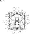
- the housing 110 houses a shutter 170 which, in a rest position, closes said orifices 125 of the cover 120.
- this shutter 170 is positioned in the rear part 110B of the interior space of the housing 110, between the cover 120 and the connection terminals 130A, 130B. More precisely, the shutter 170 is arranged between the base 151 of the yoke 150 and the entrances of the cells 132 of the phase and neutral terminals 130A.
- This shutter 170 is mounted freely in translation between a closing position (its rest position) in which it closes said orifices 125 of the cover 120 and a release position in which it frees the passage through these orifices 125.
- the movement of translation of the shutter 170 between its shutter position and its release position is carried out by inserting through the orifices 125 of the cover 120 the pins of an electrical plug plugged into the insertion well 12 of the socket. current 10.
- This translation movement is carried out against an elastic return means 180 which permanently pushes the shutter 170 into its shutter position.
- This elastic return means is a helical spring 180 compressed between the shutter 170 and an interior part of the housing 110.
- the shutter 170 has a U shape whose two branches 172 form shutters for closing the orifices 125 of the cover 120.
- the two branches 172 are interposed between the orifices 125 of the cover 120 and the inputs of cells 132 of phase and neutral terminals 130A (see the Figure 6 ).
- the shutter 170 is made in one piece by molding an insulating plastic material.
- the translation movement of the shutter 170 takes place along an axis orthogonal to the axis X of engagement of the electrical plug in the insertion well 12.
- a part of the shutter 170 is adapted to slide against a face of the base 151 of the yoke 150, during its translation between its shutter and release positions.
- the shutter 170 slides on the rear face 151B of the base 151 of the yoke 150.
- the yoke 150, and more particularly its base 151 therefore forms an element for guiding the translation movement of the shutter 170.
- the base 171 of the U-shaped shutter 170 is shaped to allow this sliding movement along the rear face 151B of the base 151 of the yoke 150.
- the base 171 of the shutter 170 comprises a groove 171A shaped to accommodate a part of the base 151 of the yoke 150. Thanks to this cooperation between the groove 171A of the base 171 of the shutter 170 and the part of the base 151 of the yoke 150, the shutter 170 is perfectly guided in translation between its shutter and release positions without it being necessary to provide additional arrangements in the box 110.
- the arrangement of the yoke 150 and the shutter 170, as close as possible to the cover 120, allows, while maintaining the electrical safety of the power socket 10, to have a larger space in the part rear 110B of the housing 110 for positioning the connection terminals 130A, 130B in this housing 110.
- the housing 110 includes arrangements 119 ( Figure 10 ) forming a stop means for the shutter 170, making it possible to block the translation of the shutter 170 in the shutter position (during its translation movement to close the orifices 125).
- Other arrangements (not shown) of the housing 110 are provided to form a stop means for the shutter 170 when it is moved to its release position by inserting an electrical plug into the insertion well 12 from the power socket 10.
- the shutter 170 For its drive from its shutter position to its release position when the electrical plug is engaged in the insertion well 12 of the power socket 10, the shutter 170 comprises, at the free end of each of its branches 172, an inclined side 172A ( figures 1, 2 , 4 , 5 , 7, 8 And 10 ). Each inclined section 172A allows the end of one of the pins of the electrical plug which is engaged in the insertion well 12 to be supported through one of the orifices 125 of the cover 120.
- each inclined side 172A is positioned on either side of the base 151 of the yoke 150, along this base 151, such that each inclined side 172A is interposes between one of the orifices 125 provided in the cover 120 and the entrance to the cells 132 phase and neutral terminals 130A housed in the housing 110.
- the front part 110A of the housing 110 is intended to receive the trim 200 of the power socket 10.
- the trim 200 is attached to the front part 110A of the housing 110 so as to close said housing 110 from the front.
- the hubcap 200 comprises hooking means (not shown) adapted to cooperate with complementary hooking means (not shown) present in the side wall 112 of the housing 110.
- the hubcap 200 comprises a cylindrical wall 202, which delimits the insertion well 12 of the power socket 10, a facade part 201 which borders laterally, at the front, this cylindrical wall 202 and a shutter 210 mounted movably inside the insertion well 12.
- the front part 201 which here has a square outline, contributes to the decorative finish of the power socket 10. It is in one piece with the cylindrical wall 202.
- the cylindrical wall 202 accommodates two pairs of side uprights 204 provided face to face (of which only one pair is shown on the figure 1 ), extending projecting from an internal face 203 of this wall cylindrical 202, parallel to the axis X of engagement.
- the two pairs of lateral uprights 204 are diametrically opposed in the insertion well 12 of the electrical socket 10 and are adapted to guide the sliding of the electrical plug in the insertion well 12 of the electrical socket 10 during its insertion .
- the internal face 203 of the cylindrical wall 202 also includes cutouts 206A through which the connection branches 152 of the yoke 150 project inside the insertion well 12 of the power socket 10. These cutouts 206A are diametrically opposed in the cylindrical wall 202.
- the internal face 203 of the cylindrical wall 202 comprises other cutouts 206B intended to accommodate the free ends 153 of the connection branches 152 of the yoke 150, in particular when, due to its insertion in the power socket 10, the plug electric presses on the connection branches 152 of the yoke 150.
- the flap 210 is movably mounted inside the cylindrical wall 202 of the hubcap 200 so as to close the section of the insertion well 12 which it delimits.
- This flap 210 forms a movable bottom of the insertion well 12.
- This flap 210 is movable in translation relative to the cylindrical wall 202, along the axis X of engagement, between two extreme positions: a raised position and a depressed position.
- the raised position (not shown) corresponds to a rest position of the hubcap 200, in which the front face 210A of the flap 210 is aesthetically flush with the front face 201A of the facade part 201 of the hubcap 200.
- the front face of the shutter could present a slight shift towards the rear compared to the front face of the front part of the hubcap.
- the depressed position corresponds to the position in which the flap 210 extends at the bottom of the insertion well 12, against the cover 120 forming the intermediate wall of the housing 110.
- the shutter 210 has a generally circular outline. As shown on the figure 1 , this contour comprises two diametrically opposed cutouts 212 for the passage of the connection branches 152 of the lyre 150. This contour comprises, according to a diameter orthogonal to that on which said cutouts 212 are placed, two pairs of right-angled notches (including one alone is represented on the figure 1 ) diametrically opposed. Each pair of notches forms a tongue 213 which cooperates with a corresponding groove 205 formed between the uprights 204 of each pair of the cylindrical wall 202. This cooperation then allows precise guidance of the movement translation of the shutter 210 between its raised and depressed positions. The bottom of each groove 205 forms a stop wall for each tongue 213 of the flap 210 which takes the depressed position.
- the flap 210 includes two circular openings 215 for the passage of the pins of the electrical plug. These two openings 215 are provided facing the orifices 125 of the cover 120 and aligned along the same axis, parallel to the axis X, as the cells 132 of the phase and neutral terminals 130A. The openings 215 and the orifices 125 are therefore aligned to allow the passage in the direction of said cells 132 of the pins of the electrical plug inserted into the insertion well 12 of the power socket 10.
- the shutter 210 is adapted to be pushed backwards, from its raised position to its depressed position, by inserting the pins of the electrical plug into the openings 215 of the shutter 210 and there exert a pushing force.
- the openings 215 of the shutter 210 extend close to the orifices 125 of the cover 120 so that the pins of the electrical plug can penetrate into the recesses 132 of the phase and neutral terminals 130A of the power socket 10 .
- the flap 210 is kept at a distance from the cover 120 thanks in particular to the presence of a sidewalk 129 which rises from the front face 120A of the cover 120, perpendicular to it.
- This makes it possible in particular to respect the standardized distance imposed between the flap 210 (forming the bottom of the hubcap 200) and the entrance to the connection terminals 130A.
- this arrangement makes it possible to respect the standardized distance of 8 ⁇ 1 millimeters between the flap 210 in the depressed position and the entrance to the cells 132 of the connection terminals 130A.
- another shutter 230 is provided secured to the flap 210 of the hubcap 200 ( figure 1 ).
- This other shutter 230 is positioned at the rear of the shutter 210, between the shutter 210 and the cover 120 of the housing 110.
- integral we mean here that the other shutter 230 is linked to the shutter 210 such that when the trim 200 is removed from the housing 110, the other shutter 230 remains assembled to the shutter 210 (and therefore to the hubcap 200).
- the other shutter 230 is mounted free to rotate between a closed position in which it closes said openings 215 and an opening position in which it frees the passage through these openings 215.
- the rotational mounting of the shutter 230 can be carried out by threading an opening of the shutter 230 on a pin linked to the shutter 210 or linked to a cassette housing said shutter and secured to said shutter 210.
- the other shutter 230 comprises two wings 232 (only one of which is visible on the figure 1 ). Each of the two wings 232 is arranged relative to each other so as to form a shutter for closing the openings 215 of the shutter 210.
- the two wings 232 are interposed between the openings 215 of the shutter 210 and the orifices 125 of the cover 120 to prevent access to the connection terminals 130A.
- the two wings 232 move away from the openings 215 to allow access to said orifices 125 of the cover 120 and therefore to the connection terminals 130A.
- the other shutter 230 pivots around the engagement axis X until the wings 232 completely free the passage to the connection terminals 130A.
- the other shutter 230 has, at the end of each of these two wings 232, a inclined pan 232A.
- Each inclined section 232A allows the end of one of the pins of the electrical plug which is engaged in the insertion well 12 to be supported through one of the openings 215 of the flap 210.
- Each inclined panel 232A is positioned on either side of the engagement axis 130A phase and neutral terminals housed in box 110.
- the movable flap 210 is held in the raised position by the associated elastic return means.
- the other shutter 230 which is held in the closed position by the associated elastic return means, then makes it possible to prevent dust particles from entering inside the power socket 10 and to prevent a simple press on the flap 210 does not cause it to sink into the insertion well 12.
- the shutter 170 is held in the shutter position by the helical spring 180.
- the electrical plug is then free to penetrate deeper into the insertion well 12 of the power socket 10, until it comes to rest against the front face 210A of the shutter 210 and pushes the latter towards its position pressed.
- the electrical plug is then free to penetrate deeper into the power socket 10, until its pins engage in the sockets 132 of the phase and neutral terminals 130A to be connected to these terminals.
- connection branches 152 of the yoke 150 Concomitantly, during the insertion movement of the electrical plug, the metal earth parts of the electric plug come into contact with the connection branches 152 of the yoke 150 to be connected to the earth terminal 130B of the power outlet 10.
- the electrical plug causes the elastic deformation of the connection branches 152 whose ends 153 engage in the cutouts 206B of the cylindrical wall 202.
- the extraction of the electrical plug from the power socket 10 causes the reverse movement of the different components of this power socket 10, thanks in particular to the different return means involved.
- the shutter 170 remains attached to the housing 110. Due to this connection, the shutter 170 makes it possible to ensure the electrical safety of the power outlet 10, even when the hubcap 200 is dismantled. The shutter 170 thus retains its role of electrical protection when the hubcap 200 is removed from the housing 110. The other shutter 230 remains attached to the hubcap 200, which facilitates the dismantling of the latter.
Landscapes
- Connector Housings Or Holding Contact Members (AREA)
Abstract
L'invention concerne une prise de courant (10) comprenant :- un boîtier (110) qui loge, à l'arrière, des bornes de connexion (130A), et, à l'avant, un enjoliveur (200), ledit boîtier comportant une paroi intermédiaire (120) qui isole lesdites bornes de la partie avant (110A) du boîtier, cette paroi intermédiaire étant percée d'orifices (125),- un obturateur (170) disposé dans ledit boîtier entre la paroi intermédiaire et les bornes, ledit obturateur étant monté libre en translation entre une position d'obturation et une position de libération,- une lyre (150) de mise à la terre présentant une base (151) qui relie deux branches (152), la base étant disposée dans ledit boîtier dans un espace situé entre les orifices, au-dessus des bornes,une partie de l'obturateur étant adaptée à glisser contre une face de la base de la lyre, lors de sa translation entre ses positions d'obturation et de libération de telle sorte que la lyre forme un élément de guidage du mouvement de l'obturateur.The invention relates to a power socket (10) comprising: - a housing (110) which houses, at the rear, connection terminals (130A), and, at the front, a trim (200), said housing comprising an intermediate wall (120) which isolates said terminals from the front part (110A) of the housing, this intermediate wall being pierced with orifices (125), - a shutter (170) disposed in said housing between the intermediate wall and the terminals , said shutter being mounted free in translation between a shutter position and a release position, - a grounding yoke (150) having a base (151) which connects two branches (152), the base being arranged in said housing in a space located between the orifices, above the terminals, a part of the shutter being adapted to slide against one face of the base of the yoke, during its translation between its shutter and release positions such that the yoke forms an element for guiding the movement of the shutter.
Description
La présente invention concerne de manière générale la sécurité des installations électriques.The present invention generally relates to the safety of electrical installations.
Elle concerne plus particulièrement une prise de courant selon un standard avec contacts de terre latéraux qui respecte la norme de sécurité IP4X même lorsque l'enjoliveur n'est pas rapporté dans le boîtier de la prise de courant.It concerns more particularly a power socket according to a standard with side earth contacts which complies with the IP4X safety standard even when the cover is not attached to the socket housing.
Plus particulièrement, on propose, selon l'invention, une prise de courant selon la revendication 1.More particularly, according to the invention, we propose a power outlet according to claim 1.
Ainsi, avantageusement, dans la prise de courant conforme à l'invention, les bornes de connexion sont enfermées dans un espace clos à l'arrière du boîtier et, grâce à l'obturateur, elles ne sont pas accessibles par l'avant tant qu'une fiche électrique n'est pas enfichée dans le puits de l'enjoliveur monté dans l'espace avant dudit boîtier. Une telle prise de courant respecte la norme de sécurité IP4X même si l'enjoliveur n'est pas monté dans l'espace avant du boîtier puisque l'obturateur est positionné dans l'espace arrière de ce boîtier fermé par ladite paroi intermédiaire.Thus, advantageously, in the power socket according to the invention, the connection terminals are enclosed in a closed space at the rear of the housing and, thanks to the shutter, they are not accessible from the front as long as 'an electrical plug is not plugged into the well of the hubcap mounted in the front space of said housing. Such a power outlet complies with the IP4X safety standard even if the bezel is not mounted in the front space of the housing since the shutter is positioned in the rear space of this housing closed by said intermediate wall.
En outre, dans la prise de courant conforme à l'invention, avantageusement, la lyre de mise à la terre présente une fonction supplémentaire puisqu'une partie de sa base, positionnée de façon adéquate dans l'espace clos prévu à l'arrière du boîtier, forme un élément de guidage qui guide l'obturateur lors de son mouvement de translation entre ses positions d'obturation et de libération.Furthermore, in the power socket according to the invention, advantageously, the earthing yoke has an additional function since part of its base, positioned adequately in the enclosed space provided at the rear of the housing, forms a guide element which guides the shutter during its translation movement between its shutter and release positions.
Dans une telle prise de courant, le mouvement de l'obturateur est précis entre ses deux positions fonctionnelles sans qu'il soit nécessaire de prévoir un aménagement supplémentaire dans le boîtier.In such a socket, the movement of the shutter is precise between its two functional positions without it being necessary to provide additional accommodation in the housing.
D'autres caractéristiques non limitatives et avantageuses de la prise de courant conforme à l'invention, prises individuellement ou selon toutes les combinaisons techniquement possibles, sont énoncées dans les revendications 2 à 12.Other non-limiting and advantageous characteristics of the power socket according to the invention, taken individually or in all technically possible combinations, are set out in
La description qui va suivre en regard des dessins annexés, donnés à titre d'exemples non limitatifs, fera bien comprendre en quoi consiste l'invention et comment elle peut être réalisée.The description which follows with reference to the appended drawings, given as non-limiting examples, will make it clear what the invention consists of and how it can be carried out.
Sur les dessins annexés :
- la
figure 1 est une vue en perspective avec un arraché partiel d'une prise de courant conforme à l'invention, - la
figure 2 est une vue en perspective avant du boîtier de la prise de courant de lafigure 1 , - la
figure 3 est une vue en perspective de trois quarts avec un arraché partiel du boîtier de lafigure 2 , - la
figure 4 est une autre vue en perspective de côté avec un arraché partiel du boîtier de lafigure 2 , - la
figure 5 est une vue en perspective éclatée du boîtier de lafigure 2 , - la
figure 6 est une vue de face du boîtier de lafigure 2 , - la
figure 7 est une vue en coupe selon le plan A-A de lafigure 6 , - la
figure 8 est une vue en coupe selon le plan B-B de lafigure 6 , - la
figure 9 est une vue en coupe selon le plan C-C de lafigure 6 , et - la
figure 10 est une vue en coupe selon le plan D-D de lafigure 6 .
- there
figure 1 is a perspective view with a partial cutaway of a power socket according to the invention, - there
figure 2 is a front perspective view of the power outlet housing of thefigure 1 , - there
Figure 3 is a three-quarter perspective view with a partial cut-out of the housing of thefigure 2 , - there
Figure 4 is another side perspective view with a partial tear-away of the housing of thefigure 2 , - there
Figure 5 is an exploded perspective view of the housing of thefigure 2 , - there
Figure 6 is a front view of the housing of thefigure 2 , - there
Figure 7 is a sectional view according to plan AA of theFigure 6 , - there
figure 8 is a sectional view according to plan BB of theFigure 6 , - there
Figure 9 is a sectional view according to the CC plan of theFigure 6 , And - there
Figure 10 is a sectional view according to the DD plan of theFigure 6 .
Par convention, les termes « avant » et « arrière » seront utilisés par rapport à la direction du regard de l'utilisateur tourné vers la prise électrique montée dans la paroi. Ainsi, l'avant d'un élément désignera le côté de cet élément qui est tourné vers l'utilisateur, et l'arrière désignera le côté opposé.By convention, the terms "front" and "rear" will be used in relation to the direction of the user's gaze turned towards the electrical outlet mounted in the wall. So, the front of an element will designate the side of that element that faces the user, and the back will designate the opposite side.
Les termes « intérieur » et « extérieur » seront utilisés en référence à la prise de courant elle-même, pour désigner respectivement le côté d'un élément tourné vers le centre de la prise de courant et le côté d'un élément tourné vers l'extérieur de cette prise.The terms "interior" and "exterior" will be used in reference to the socket itself, to designate respectively the side of an element facing the center of the socket and the side of an element facing the outside of this socket.
Les
La prise de courant 10 est destinée à être montée dans un support d'appareillage (non représenté) lui-même destiné à être positionné soit dans une boîte électrique encastrée ou rapportée en saillie sur une paroi quelconque, soit dans une goulotte. En variante, cette prise de courant pourrait être une prise de type rallonge, ou faire partie d'un bloc multiprises, sans que le principe de l'invention ne soit modifié.The
Comme le montre la
Comme le montrent les
Comme cela est visible sur la
Comme le montrent les
La partie arrière 110B est un espace clos qui s'étend entre le fond 111 du boîtier 110 et ledit capot 120 (voir
Le capot 120 est formé par une plaquette dont la face avant 120A globalement plane s'étend sensiblement parallèlement au fond 111 du boîtier 110.The
Comme le montre la
La partie arrière 110B du boîtier 110 loge les éléments de contact électrique de la prise de courant 10. Ces éléments électriques comprennent trois bornes de connexion 130A, 130B : une borne de phase 130A, une borne de neutre 130A et une borne de terre 130B (
Comme cela est représenté sur les
Les alvéoles 132 sont situés en regard de deux orifices 125 circulaires prévus dans le capot 120 pour le passage des broches de la fiche électrique correspondante.The
Lorsque la fiche électrique est insérée dans la prise de courant 10, les broches de cette fiche électrique traversent les orifices 125 du capot 120 et pénètrent dans les alvéoles 132 des bornes de phase et de neutre 130A.When the electrical plug is inserted into the
Il est prévu, dans une partie arrière de la paroi latérale 112 du boîtier 110, des ouvertures (non visibles sur les figures) dans lesquelles sont engagés des leviers de déconnexion 135 grâce auxquels on peut agir sur les lames ressort de contact 131 des bornes de connexion 130A, 130B pour libérer l'âme dénudée des conducteurs électriques connectés auxdites bornes de connexion 130A, 130B.There are provided, in a rear part of the
La prise de courant 10 représentée sur les
Chacune des branches de connexion 152 forme un angle inférieur à 90 degrés par rapport à la base 151 (
Comme cela est visible sur la
Comme le montrent les
Plus particulièrement, comme le montrent les
Comme le montrent les
Par ailleurs, dans cette position centrée, la base 151 de la lyre 150 est prise en sandwich entre un aménagement intérieur du boîtier 110 et la face arrière de la tête d'un plot 160 issu du boîtier 110 (voir
Comme cela est représenté sur la
Cette barrette 127 s'étend au centre de l'ouverture 126 du capot 120 (
De plus, la barrette 127 est formée, en saillie, à l'avant du capot 120. Ainsi, de manière avantageuse, la base 151 de la lyre 150 est positionnée dans l'épaisseur du capot 120, la face avant 151A de la base 151 de la lyre 150 étant légèrement décalée vers l'arrière par rapport à la face avant 120A du capot 120 (
La lyre 150 est également maintenue dans la paroi latérale 112 car la partie incurvée de chaque branche de connexion 152 qui se raccorde à la base 151, est engagée dans une rainure 118 formée dans l'épaisseur de la paroi latérale 112 et repose sur le fond 117 de cette rainure 118 (voir
La solidarisation de la base 151 de la lyre 150 au capot 120 permet de remonter au maximum la lyre 150 dans le boîtier 110 et donc de gagner de l'espace dans la partie arrière 110B du boîtier 110 pour le positionnement des bornes de connexions 130A, 130B dans ce boîtier 110.The joining of the
De manière avantageuse selon l'invention, pour assurer la sécurité électrique de la prise de courant 10, notamment lorsque l'enjoliveur 200 n'est pas rapporté dans le boîtier 110, le boîtier 110 loge un obturateur 170 qui, dans une position repos, obture lesdits orifices 125 du capot 120.Advantageously according to the invention, to ensure the electrical safety of the
Comme le montrent les
Cet obturateur 170 est monté libre en translation entre une position d'obturation (sa position repos) dans laquelle il obture lesdits orifices 125 du capot 120 et une position de libération dans laquelle il libère le passage au travers de ces orifices 125. Le mouvement de translation de l'obturateur 170 entre sa position d'obturation et sa position de libération est réalisé par l'insertion au travers des orifices 125 du capot 120 des broches d'une fiche électrique enfichée dans le puits d'insertion 12 de la prise de courant 10. Ce mouvement de translation est réalisé à l'encontre d'un moyen élastique de rappel 180 qui pousse en permanence l'obturateur 170 dans sa position d'obturation. Ce moyen élastique de rappel est un ressort hélicoïdal 180 comprimé entre l'obturateur 170 et une partie intérieure du boîtier 110.This
Comme cela est représenté sur la
L'obturateur 170 est réalisé d'une seule pièce par moulage d'une matière plastique isolante.The
Le mouvement de translation de l'obturateur 170 s'effectue selon un axe orthogonal à l'axe X d'engagement de la fiche électrique dans le puits d'insertion 12.The translation movement of the
De manière particulièrement avantageuse selon l'invention, une partie de l'obturateur 170 est adaptée à glisser contre une face de la base 151 de la lyre 150, lors de sa translation entre ses positions d'obturation et de libération. Ici, l'obturateur 170 glisse sur la face arrière 151B de la base 151 de la lyre 150. La lyre 150, et plus particulièrement sa base 151, forme donc un élément de guidage du mouvement de translation de l'obturateur 170.In a particularly advantageous manner according to the invention, a part of the
La base 171 de la forme en U de l'obturateur 170 est conformée pour permettre ce mouvement de glissement le long de la face arrière 151B de la base 151 de la lyre 150. Comme le montrent les
De plus, l'agencement de la lyre 150 et de l'obturateur 170, au plus proche du capot 120, permet, tout en maintenant la sécurité électrique de la prise de courant 10, de disposer d'un plus grand espace dans la partie arrière 110B du boîtier 110 pour le positionnement des bornes de connexion 130A, 130B dans ce boîtier 110.In addition, the arrangement of the
Par ailleurs, le boîtier 110 comporte des aménagements 119 (
Pour son entraînement depuis sa position d'obturation vers sa position de libération lorsque la fiche électrique est engagée dans le puits d'insertion 12 de la prise de courant 10, l'obturateur 170 comprend, à l'extrémité libre de chacune de ses branches 172, un pan incliné 172A (
Etant donnée la forme en U de l'obturateur 170, chaque pan incliné 172A est positionné de part et d'autre de la base 151 de la lyre 150, le long de cette base 151, de telle sorte que chaque pan incliné 172A s'interpose entre l'un des orifices 125 prévus dans le capot 120 et l'entrée des alvéoles 132 des bornes de phase et de neutre 130A logées dans le boîtier 110.Given the U shape of the
L'inclinaison de ces pans inclinés 172A est prévue de telle manière que lorsque les broches de la fiche électrique sont engagées au travers des orifices 125 du capot 120 et appuient sur ces pans inclinés 172A, elles provoquent le déplacement de l'obturateur 170 vers sa position de libération. Cela permet alors aux broches de librement accéder aux alvéoles 132 des bornes de phase et de neutre 130A de la prise de courant 10.The inclination of these
La partie avant 110A du boîtier 110 est destinée à recevoir l'enjoliveur 200 de la prise de courant 10. L'enjoliveur 200 est rapporté dans la partie avant 110A du boîtier 110 de manière à fermer ledit boîtier 110 par l'avant. L'enjoliveur 200 comporte à cet effet des moyens d'accrochage (non représentés) adaptés à coopérer avec des moyens d'accrochage complémentaires (non représentés) présents dans la paroi latérale 112 du boîtier 110.The
Comme le montre la
La partie de façade 201, qui présente ici un contour carré, participe à la finition décorative de la prise de courant 10. Elle est monobloc avec la paroi cylindrique 202.The
La paroi cylindrique 202 accueille deux couples de montants latéraux 204 prévus face à face (dont un seul couple est représenté sur la
Comme le montre la
La face interne 203 de la paroi cylindrique 202 comprend d'autres découpes 206B destinées à accueillir les extrémités libres 153 des branches de connexion 152 de la lyre 150, en particulier lorsque, du fait de son insertion dans la prise de courant 10, la fiche électrique appuie sur les branches de connexion 152 de la lyre 150.The
Comme le montre la
Ce volet 210 est mobile en translation par rapport à la paroi cylindrique 202, le long de l'axe X d'engagement, entre deux positions extrêmes : une position relevée et une position enfoncée. La position relevée (non représentée) correspond à une position de repos de l'enjoliveur 200, dans laquelle la face avant 210A du volet 210 affleure esthétiquement la face avant 201A de la partie de façade 201 de l'enjoliveur 200. En variante, dans la position relevée, la face avant du volet pourrait présenter un léger décalage vers l'arrière par rapport à la face avant de la partie de façade de l'enjoliveur.This
La position enfoncée, représentée sur la
Le volet 210 présente un contour globalement circulaire. Comme cela est représenté sur la
Comme le montre la
En conditions normales d'utilisation, le volet 210 est adapté à être repoussé vers l'arrière, depuis sa position relevée vers sa position enfoncée, par l'insertion des broches de la fiche électrique dans les ouvertures 215 du volet 210 et d'y exercer une force de poussée. En position enfoncée, les ouvertures 215 du volet 210 s'étendent à proximité des orifices 125 du capot 120 de sorte que les broches de la fiche électrique peuvent pénétrer dans les alvéoles 132 des bornes de phase et de neutre 130A de la prise de courant 10.Under normal conditions of use, the
En pratique, en position enfoncée, le volet 210 est maintenu à distance du capot 120 grâce notamment à la présence d'un trottoir 129 qui s'élève à partir de la face avant 120A du capot 120, perpendiculairement à celle-ci. Cela permet notamment de respecter la distance normalisée imposée entre le volet 210 (formant le fond de l'enjoliveur 200) et l'entrée des bornes de connexion 130A. En particulier, cet agencement permet de respecter la distance normalisée de 8 ± 1 millimètres entre le volet 210 en position enfoncée et l'entrée des alvéoles 132 des bornes de connexion 130A.In practice, in the depressed position, the
Pour que le volet 210 revienne en position relevée lorsque les broches de la fiche électrique sont extraites de la prise de courant 10, il est prévu des moyens de rappel élastique (non représentés) de ce volet 210. Ces moyens de rappel du volet 210 exercent en permanence une force tendant à ramener le volet 210 en position relevée. Ainsi, dès que les broches de la fiche électrique sont retirées des alvéoles 132 de la prise de courant 10, le volet 210 remonte automatiquement vers sa position relevée.So that the
De manière avantageuse, pour renforcer la sécurité électrique de la prise de courant 10, il est prévu un autre obturateur 230 solidarisé au volet 210 de l'enjoliveur 200 (
Par « solidarisé », on entend ici que l'autre obturateur 230 est lié au volet 210 de telle sorte que lorsque l'enjoliveur 200 est démonté du boîtier 110, l'autre obturateur 230 reste assemblé au volet 210 (et donc à l'enjoliveur 200).By "integral", we mean here that the
Afin d'assurer sa fonction de sécurité, et permettre l'obturation des ouvertures 215 du volet 210 lorsqu'aucune fiche électrique n'y est insérée, l'autre obturateur 230 est monté libre en rotation entre une position de fermeture dans laquelle il obture lesdites ouvertures 215 et une position d'ouverture dans laquelle il libère le passage au travers de ces ouvertures 215. Le montage à rotation de l'obturateur 230 peut être réalisé en enfilant une ouverture de l'obturateur 230 sur un tourillon lié au volet 210 ou lié à une cassette logeant ledit obturateur et solidarisée audit volet 210.In order to ensure its safety function, and to allow the closing of the
Comme cela est visible sur la
Ainsi, en position de fermeture, les deux ailes 232 s'interposent entre les ouvertures 215 du volet 210 et les orifices 125 du capot 120 pour interdire l'accès aux bornes de connexion 130A. En position d'ouverture, les deux ailes 232 s'écartent des ouvertures 215 pour autoriser l'accès auxdits orifices 125 du capot 120 et donc aux bornes de connexion 130A.Thus, in the closed position, the two
Pour autoriser l'accès aux bornes de connexion 130A, l'autre obturateur 230 pivote autour de l'axe X d'engagement jusqu'à ce que les ailes 232 libèrent totalement le passage vers les bornes de connexion 130A. Comme le montre la
Chaque pan incliné 232A est positionné de part et d'autre de l'axe X d'engagement de telle sorte que chaque pan incliné 232A s'interpose entre l'une des ouvertures 215 prévues dans le volet 210 et l'entrée des alvéoles 132 des bornes de phase et de neutre 130A logées dans le boîtier 110.Each
L'inclinaison de ces pans inclinés 232A est prévue de telle manière que lorsque les broches de la fiche électrique sont engagées au travers des ouvertures 215 prévues dans le volet 210 et appuient sur ces pans inclinés 232A, elles provoquent le déplacement de l'autre obturateur 230 vers sa position d'ouverture. Cela permet alors aux broches de librement accéder aux bornes de phase et de neutre 130A de la prise de courant 10.The inclination of these
Pour que l'autre obturateur 230 revienne en position de fermeture lorsque les broches de la fiche électrique sont extraites de la prise de courant 10, il est prévu des moyens de rappel élastique (non visibles) de cet autre obturateur 230. Ces moyens de rappel sont par exemple formés par un ressort de torsion agissant sur ledit autre obturateur 230.So that the
Nous allons maintenant décrire les mouvements des différents composants de la prise de courant 10 lors de l'insertion d'une fiche électrique dans le puits d'insertion 12 de cette prise de courant 10.We will now describe the movements of the different components of the
Initialement, le volet mobile 210 est maintenu en position relevée par les moyens de rappel élastique associés.Initially, the
L'autre obturateur 230, qui est maintenu en position de fermeture par les moyens de rappel élastique associés, permet alors d'éviter que des particules de poussière n'entrent à l'intérieur de la prise de courant 10 et d'éviter qu'un simple appui sur le volet 210 ne provoque l'enfoncement de celui-ci dans le puits d'insertion 12.The
L'obturateur 170 est quant à lui maintenu en position d'obturation par le ressort hélicoïdal 180.The
Lorsqu'un usager engage une fiche électrique dans le puits d'insertion 12 de la prise de courant 10, les broches de cette fiche électrique traversent les ouvertures 215 du volet 210 et viennent en appui contre les pans inclinés 232A de l'autre obturateur 230, ce qui provoque le pivotement de ce dernier.When a user inserts an electrical plug into the insertion well 12 of the
La fiche électrique est alors libre de pénétrer plus en profondeur dans le puits d'insertion 12 de la prise de courant 10, jusqu'à ce qu'elle vienne en appui contre la face avant 210A du volet 210 et repousse ce dernier vers sa position enfoncée.The electrical plug is then free to penetrate deeper into the insertion well 12 of the
Lors de ce mouvement, les broches de la fiche électrique traversent les orifices 125 du capot 120 et viennent en appui contre les pans inclinés 172A de l'obturateur 170, ce qui provoque le glissement en translation de ce dernier sur la face arrière 151B de la base 151 de la lyre 150 vers sa position de libération en comprimant le ressort hélicoïdal 180.During this movement, the pins of the electrical plug pass through the
La fiche électrique est alors libre de pénétrer plus en profondeur dans la prise de courant 10, jusqu'à ce que ses broches s'engagent dans les alvéoles 132 des bornes de phase et de neutre 130A pour être connectées à ces bornes.The electrical plug is then free to penetrate deeper into the
De manière concomitante, lors du mouvement d'insertion de la fiche électrique, les parties métalliques de terre de la fiche électrique viennent au contact des branches de connexion 152 de la lyre 150 pour être raccordées à la borne de terre 130B de la prise de courant 10. La fiche électrique provoque la déformation élastique des branches de connexion 152 dont les extrémités 153 s'engagent dans les découpes 206B de la paroi cylindrique 202.Concomitantly, during the insertion movement of the electrical plug, the metal earth parts of the electric plug come into contact with the
L'extraction de la fiche électrique hors de la prise de courant 10 provoque le mouvement inverse des différents composants de cette prise de courant 10, grâce notamment aux différents moyens de rappel impliqués.The extraction of the electrical plug from the
On notera enfin que lors du démontage de l'enjoliveur 200, l'obturateur 170 reste solidaire du boîtier 110. Du fait de cette solidarisation, l'obturateur 170 permet d'assurer la sécurité électrique de la prise de courant 10, même lorsque que l'enjoliveur 200 est démonté. L'obturateur 170 conserve ainsi son rôle de protection électrique lorsque l'enjoliveur 200 est démonté du boîtier 110. L'autre obturateur 230 reste quant à lui solidaire de l'enjoliveur 200, ce qui facilite le démontage de ce dernier.Finally, note that when the
La présente invention n'est pas limitée aux modes de réalisation décrits et représentés sur les différentes figures, mais l'homme du métier saura y apporter toute variante conforme à l'invention.The present invention is not limited to the embodiments described and represented in the various figures, but those skilled in the art will be able to make any variation conforming to the invention.
Claims (12)
Applications Claiming Priority (1)
| Application Number | Priority Date | Filing Date | Title |
|---|---|---|---|
| FR2202159A FR3133487B1 (en) | 2022-03-11 | 2022-03-11 | Standard socket outlet with reinforced safety side earth contacts |
Publications (1)
| Publication Number | Publication Date |
|---|---|
| EP4243219A1 true EP4243219A1 (en) | 2023-09-13 |
Family
ID=81749140
Family Applications (1)
| Application Number | Title | Priority Date | Filing Date |
|---|---|---|---|
| EP23158622.3A Pending EP4243219A1 (en) | 2022-03-11 | 2023-02-24 | Standard socket with lateral earth contacts with enhanced security |
Country Status (2)
| Country | Link |
|---|---|
| EP (1) | EP4243219A1 (en) |
| FR (1) | FR3133487B1 (en) |
Citations (4)
| Publication number | Priority date | Publication date | Assignee | Title |
|---|---|---|---|---|
| ES2147706A1 (en) * | 1998-03-20 | 2000-09-16 | Interlander Patermann S L | Modular plug assembly for surface mechanisms |
| EP2555336A1 (en) * | 2011-08-04 | 2013-02-06 | Legrand France | Socket provided with two shutters |
| EP2797174A1 (en) * | 2011-12-22 | 2014-10-29 | Sung Tae Ro | Safe electrical outlet |
| EP3836315A1 (en) * | 2019-12-10 | 2021-06-16 | Legrand France | Power socket |
-
2022
- 2022-03-11 FR FR2202159A patent/FR3133487B1/en active Active
-
2023
- 2023-02-24 EP EP23158622.3A patent/EP4243219A1/en active Pending
Patent Citations (4)
| Publication number | Priority date | Publication date | Assignee | Title |
|---|---|---|---|---|
| ES2147706A1 (en) * | 1998-03-20 | 2000-09-16 | Interlander Patermann S L | Modular plug assembly for surface mechanisms |
| EP2555336A1 (en) * | 2011-08-04 | 2013-02-06 | Legrand France | Socket provided with two shutters |
| EP2797174A1 (en) * | 2011-12-22 | 2014-10-29 | Sung Tae Ro | Safe electrical outlet |
| EP3836315A1 (en) * | 2019-12-10 | 2021-06-16 | Legrand France | Power socket |
Also Published As
| Publication number | Publication date |
|---|---|
| FR3133487B1 (en) | 2024-02-23 |
| FR3133487A1 (en) | 2023-09-15 |
Similar Documents
| Publication | Publication Date | Title |
|---|---|---|
| EP2456024B1 (en) | Electric socket comprising a shutter | |
| EP2555336B1 (en) | Socket provided with two shutters | |
| FR2720197A1 (en) | Connector for electric cable. | |
| EP3605749B9 (en) | Support for electrical equipment and associated electrical equipment | |
| EP2456021B1 (en) | Electric socket comprising translatably mobile side posts | |
| EP4243219A1 (en) | Standard socket with lateral earth contacts with enhanced security | |
| EP1865578B1 (en) | Self-stripping terminal for an insulated electrical conductor and electrical equipment comprising such a terminal | |
| FR3104331A1 (en) | Plug | |
| EP3840136B1 (en) | Mechanism for electrical equipment, associated electrical assembly and electrical equipment | |
| EP1865579B1 (en) | Self-stripping drop terminal and electrical equipment equipped with such a terminal | |
| EP3255732B1 (en) | Electrical connection terminal comprising a connection lever and associated electrical switchgear | |
| FR2945893A1 (en) | Power socket for receiving electrical plug, has security lock occupying locking and releasing positions and formed from piece distinct from metallic strip of earth pin, where piece is movably mounted at back of trimming cover | |
| EP3605750B1 (en) | Mechanism for electrical equipment and associated electrical equipment | |
| FR2967292A1 (en) | PUSH-PUSH TYPE ELECTRICAL SWITCH | |
| FR3135839A1 (en) | Electrical terminal block provided with a male element and a female electrical connection element. | |
| FR2974456A1 (en) | MULTI-APPARATUS BLOCK EQUIPPED WITH WALL MOUNTING MEANS | |
| WO2023198438A1 (en) | Electrical socket comprising a moveable plunger | |
| CH716357B1 (en) | Electrical modular device provided with a blocking element. | |
| FR3010240A1 (en) | ELECTRICAL DEVICE COMPRISING AN ELECTRIC CIRCUIT PRINTED ON A SUPPORT PLATE AND AN ELECTRICAL CONNECTION TERMINAL | |
| FR3135835A1 (en) | Electrical device with automatic connection terminal operated by the insertion of the electrical conductor | |
| EP4191796A1 (en) | Key system for disconnecting automatic terminals, apparatus mechanism comprising said system, and method for manufacturing said system | |
| EP1317022A1 (en) | Electrical socket with independent movable covers, especially for electrical rasors | |
| FR2931590A1 (en) | American electrical socket installation mechanism, has liner including connection pad whose support surface is extended along axis of opening towards base wall so as to form support for pin, and connection terminal housed in base | |
| FR2931592A1 (en) | Indian electrical socket, has rigid guiding wall extended between cover and opening, along direction orthogonal to plane of opening and extended along circular arc ranging between specific degrees | |
| EP2320532A1 (en) | Device for installing a frame upright on the bottom of an electric box and electric box including such a device |
Legal Events
| Date | Code | Title | Description |
|---|---|---|---|
| PUAI | Public reference made under article 153(3) epc to a published international application that has entered the european phase |
Free format text: ORIGINAL CODE: 0009012 |
|
| STAA | Information on the status of an ep patent application or granted ep patent |
Free format text: STATUS: THE APPLICATION HAS BEEN PUBLISHED |
|
| AK | Designated contracting states |
Kind code of ref document: A1 Designated state(s): AL AT BE BG CH CY CZ DE DK EE ES FI FR GB GR HR HU IE IS IT LI LT LU LV MC ME MK MT NL NO PL PT RO RS SE SI SK SM TR |
|
| STAA | Information on the status of an ep patent application or granted ep patent |
Free format text: STATUS: REQUEST FOR EXAMINATION WAS MADE |
|
| 17P | Request for examination filed |
Effective date: 20240308 |
|
| RBV | Designated contracting states (corrected) |
Designated state(s): AL AT BE BG CH CY CZ DE DK EE ES FI FR GB GR HR HU IE IS IT LI LT LU LV MC ME MK MT NL NO PL PT RO RS SE SI SK SM TR |