EP4243219A1 - Standardsteckdose mit sicherheitsverstärkten seitenerdkontakten - Google Patents
Standardsteckdose mit sicherheitsverstärkten seitenerdkontakten Download PDFInfo
- Publication number
- EP4243219A1 EP4243219A1 EP23158622.3A EP23158622A EP4243219A1 EP 4243219 A1 EP4243219 A1 EP 4243219A1 EP 23158622 A EP23158622 A EP 23158622A EP 4243219 A1 EP4243219 A1 EP 4243219A1
- Authority
- EP
- European Patent Office
- Prior art keywords
- shutter
- housing
- power socket
- intermediate wall
- base
- Prior art date
- Legal status (The legal status is an assumption and is not a legal conclusion. Google has not performed a legal analysis and makes no representation as to the accuracy of the status listed.)
- Pending
Links
- 238000003780 insertion Methods 0.000 claims description 28
- 230000037431 insertion Effects 0.000 claims description 28
- 230000007935 neutral effect Effects 0.000 claims description 13
- 230000000994 depressogenic effect Effects 0.000 claims description 9
- 230000000295 complement effect Effects 0.000 description 3
- 239000002184 metal Substances 0.000 description 3
- 239000004020 conductor Substances 0.000 description 2
- 239000000463 material Substances 0.000 description 2
- 230000004308 accommodation Effects 0.000 description 1
- 239000000428 dust Substances 0.000 description 1
- 230000005489 elastic deformation Effects 0.000 description 1
- 238000010616 electrical installation Methods 0.000 description 1
- 238000000605 extraction Methods 0.000 description 1
- 239000011810 insulating material Substances 0.000 description 1
- 239000007769 metal material Substances 0.000 description 1
- 239000002991 molded plastic Substances 0.000 description 1
- 238000000465 moulding Methods 0.000 description 1
- 239000002245 particle Substances 0.000 description 1
- 230000002093 peripheral effect Effects 0.000 description 1
- 239000004033 plastic Substances 0.000 description 1
Images


Classifications
-
- H—ELECTRICITY
- H01—ELECTRIC ELEMENTS
- H01R—ELECTRICALLY-CONDUCTIVE CONNECTIONS; STRUCTURAL ASSOCIATIONS OF A PLURALITY OF MUTUALLY-INSULATED ELECTRICAL CONNECTING ELEMENTS; COUPLING DEVICES; CURRENT COLLECTORS
- H01R13/00—Details of coupling devices of the kinds covered by groups H01R12/70 or H01R24/00 - H01R33/00
- H01R13/44—Means for preventing access to live contacts
- H01R13/447—Shutter or cover plate
- H01R13/453—Shutter or cover plate opened by engagement of counterpart
- H01R13/4532—Rotating shutter
-
- H—ELECTRICITY
- H01—ELECTRIC ELEMENTS
- H01R—ELECTRICALLY-CONDUCTIVE CONNECTIONS; STRUCTURAL ASSOCIATIONS OF A PLURALITY OF MUTUALLY-INSULATED ELECTRICAL CONNECTING ELEMENTS; COUPLING DEVICES; CURRENT COLLECTORS
- H01R13/00—Details of coupling devices of the kinds covered by groups H01R12/70 or H01R24/00 - H01R33/00
- H01R13/44—Means for preventing access to live contacts
- H01R13/447—Shutter or cover plate
- H01R13/453—Shutter or cover plate opened by engagement of counterpart
- H01R13/4534—Laterally sliding shutter
-
- H—ELECTRICITY
- H01—ELECTRIC ELEMENTS
- H01R—ELECTRICALLY-CONDUCTIVE CONNECTIONS; STRUCTURAL ASSOCIATIONS OF A PLURALITY OF MUTUALLY-INSULATED ELECTRICAL CONNECTING ELEMENTS; COUPLING DEVICES; CURRENT COLLECTORS
- H01R13/00—Details of coupling devices of the kinds covered by groups H01R12/70 or H01R24/00 - H01R33/00
- H01R13/648—Protective earth or shield arrangements on coupling devices, e.g. anti-static shielding
- H01R13/655—Protective earth or shield arrangements on coupling devices, e.g. anti-static shielding with earth brace
-
- H—ELECTRICITY
- H01—ELECTRIC ELEMENTS
- H01R—ELECTRICALLY-CONDUCTIVE CONNECTIONS; STRUCTURAL ASSOCIATIONS OF A PLURALITY OF MUTUALLY-INSULATED ELECTRICAL CONNECTING ELEMENTS; COUPLING DEVICES; CURRENT COLLECTORS
- H01R2103/00—Two poles
-
- H—ELECTRICITY
- H01—ELECTRIC ELEMENTS
- H01R—ELECTRICALLY-CONDUCTIVE CONNECTIONS; STRUCTURAL ASSOCIATIONS OF A PLURALITY OF MUTUALLY-INSULATED ELECTRICAL CONNECTING ELEMENTS; COUPLING DEVICES; CURRENT COLLECTORS
- H01R24/00—Two-part coupling devices, or either of their cooperating parts, characterised by their overall structure
- H01R24/76—Two-part coupling devices, or either of their cooperating parts, characterised by their overall structure with sockets, clips or analogous contacts and secured to apparatus or structure, e.g. to a wall
- H01R24/78—Two-part coupling devices, or either of their cooperating parts, characterised by their overall structure with sockets, clips or analogous contacts and secured to apparatus or structure, e.g. to a wall with additional earth or shield contacts
Definitions
- the present invention generally relates to the safety of electrical installations.
- connection terminals are enclosed in a closed space at the rear of the housing and, thanks to the shutter, they are not accessible from the front as long as 'an electrical plug is not plugged into the well of the hubcap mounted in the front space of said housing.
- a power outlet complies with the IP4X safety standard even if the bezel is not mounted in the front space of the housing since the shutter is positioned in the rear space of this housing closed by said intermediate wall.
- the earthing yoke has an additional function since part of its base, positioned adequately in the enclosed space provided at the rear of the housing, forms a guide element which guides the shutter during its translation movement between its shutter and release positions.
- front and rear will be used in relation to the direction of the user's gaze turned towards the electrical outlet mounted in the wall. So, the front of an element will designate the side of that element that faces the user, and the back will designate the opposite side.
- THE figures 1 to 10 represent a power socket 10 according to a standard with side earth contacts.
- This power socket 10 includes an insertion well 12 ( figure 1 ) adapted to receive an electrical plug for the electrical connection of this electrical plug to an electrical network.
- the power socket 10 is intended to be mounted in an equipment support (not shown) itself intended to be positioned either in a recessed electrical box or attached projecting from any wall, or in a trunking.
- this power socket could be an extension type socket, or be part of a multiple socket block, without the principle of the invention being modified.
- the power socket 10 comprises a mechanism 100 comprising an insulating housing 110 housing electrical elements and a hubcap 200 attached to the housing 110.
- the hubcap 200 forms the insertion well 12 of the power socket 10.
- the well The insertion 12 here presents an axis X for engaging the corresponding electrical plug (visible on the figure 1 ).
- the housing 110 is made of molded plastic material. Here it has a generally parallelepiped shape which has an interior space open towards the front.
- the housing 110 has a bottom 111 bordered by a side wall 112 which delimits the interior space.
- the side wall 112 has four sides, two by two opposite each other, which rise from the bottom 111, substantially perpendicular to it.
- Wall lateral 112 has a free peripheral front edge 115 which delimits the front opening of the housing 110.
- the housing 110 houses a cover 120, made of insulating material, which forms an intermediate wall dividing the interior space of the housing 110 into two parts: a front part 110A and a rear part 110B.
- the rear part 110B is a closed space which extends between the bottom 111 of the housing 110 and said cover 120 (see figures 7 to 9 ) while the front part 110A is an open space which extends between the cover 120 and the front opening of the housing 110.
- the cover 120 is formed by a plate whose generally flat front face 120A extends substantially parallel to the bottom 111 of the housing 110.
- the cover 120 comprises fixing means intended to cooperate with complementary fixing means of the housing 110.
- the cover 120 carries on three adjacent sides tabs provided with anti-tearing teeth 122 adapted to hang on edges 114 provided in the side wall 112.
- the cover 120 rests on arrangements (not visible in the figures) formed in the side wall 112 of the housing 110 in such a way that it closes the section of the interior space of the housing 110.
- the rear part 110B of the housing 110 houses the electrical contact elements of the power socket 10. These electrical elements include three connection terminals 130A, 130B: a phase terminal 130A, a neutral terminal 130A and an earth terminal 130B ( Figure 5 ). Each of the connection terminals 130A, 130B must be supplied with current via a conductor coming from the network.
- each of the phase and neutral terminals 130A is an automatic connection terminal with a contact leaf spring 131 and a socket 132 for receiving a pin of an electrical plug plugged into the power socket.
- the terminal terminal 130B is also an automatic leaf spring contact connection terminal 131.
- the cells 132 are located opposite two circular orifices 125 provided in the cover 120 for the passage of the pins of the corresponding electrical plug.
- the pins of this electrical plug pass through the orifices 125 of the cover 120 and enter the cells 132 of the phase and neutral terminals 130A.
- connection terminals 130A, 130B There are provided, in a rear part of the side wall 112 of the housing 110, openings (not visible in the figures) in which disconnection levers 135 are engaged by which we can act on the contact spring blades 131 of the connection terminals 130A, 130B to release the stripped core of the electrical conductors connected to said connection terminals 130A, 130B.
- the power socket 10 shown on the figures 1 to 10 is a power outlet according to a standard with side earth contacts, in which earthing is carried out via a yoke 150 of metallic material connected to said earth terminal 130B.
- the lyre 150 is conventionally obtained by cutting and folding a metal strip. It comprises a base 151 in the form of a flat strip which connects two symmetrical connection branches 152 ( figures 1 to 7, 9 and 10 ).
- the base 151 of the yoke 150 has a parallel front face 151A and a rear face 151B.
- connection branches 152 forms an angle less than 90 degrees relative to the base 151 ( figures 1 , 3 to 5, 9 and 10 ).
- Each of the connection branches 152 has a substantially 5-shaped shape which is connected to the base 151 of the yoke 150 by a part curved towards the center of the power socket. In this way the connection branches 152 of the yoke 150 are capable of slightly deforming elastically to come into contact with the corresponding metal part of the electrical plug plugged into the insertion well 12 of the power socket 10.
- connection branches 152 of the yoke 150 emerge in the insertion well 12 of the power socket 10.
- the shape of the connection branches 152 towards the side wall 112 of the housing 110 allows their support against complementary contact zones of the electrical plug when it is inserted into the socket 10.
- the base 151 of the yoke 150 is arranged in the rear space 110B of the interior space of the housing 110 in a space between the cover 120 and the connection terminals 130A.
- the base 151 of the yoke 150 is arranged under the cover 120, in a space located between the two orifices 125 of the cover 120 and above the connection terminals 130A.
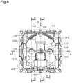
- the cover 120 has, in a central part, an opening 126 intended to accommodate the base 151 of the yoke 150 so as to position the yoke 150 centrally in the housing 110.
- the base 151 of the yoke 150 is pressed against part of the rear face of the cover 120 by filling this opening 126.
- part of the base 151 of the yoke 150 appears through the opening 126.
- the base 151 of the yoke 150 is sandwiched between an interior arrangement of the housing 110 and the rear face of the head of a stud 160 coming from the housing 110 (see figures 2 and 9 ).
- the base 151 of the lyre 150 comprises an opening 151C positioned substantially in the center of this base 151.
- the slotted head of the stud 160 passes through the opening 151C of the base 151 of the yoke 150, to cooperate by snap-fastening with a bar 127 belonging to the cover 120 so that the rear face of the head of the stud 160 rests against the front face 151A of the base 151 of the yoke 150 while a central part of the rear face 151B of the base 151 of the yoke 150 rests against said interior arrangements of the housing 110 (see Figure 9 ).
- This bar 127 extends to the center of the opening 126 of the cover 120 ( figures 2 to 4 , 6 and 9 ) from one longitudinal edge to the other of this opening 126.
- the bar 127 is formed, projecting, at the front of the cover 120.
- the base 151 of the yoke 150 is positioned in the thickness of the cover 120, the front face 151A of the base 151 of the yoke 150 being slightly offset towards the rear relative to the front face 120A of the cover 120 ( Figure 3 And 9 ).
- the yoke 150 is also held in the side wall 112 because the curved part of each connection branch 152 which connects to the base 151, is engaged in a groove 118 formed in the thickness of the side wall 112 and rests on the bottom 117 of this groove 118 (see figures 2 And 3 ).
- the edges of the grooves 118 hold said connection branches 152 laterally, the bottom of the grooves 118 holds the yoke 150 rearwardly.
- the joining of the base 151 of the yoke 150 to the cover 120 makes it possible to raise the yoke 150 as much as possible in the housing 110 and therefore to save space in the rear part 110B of the housing 110 for the positioning of the connection terminals 130A, 130B in this housing 110.
- the housing 110 houses a shutter 170 which, in a rest position, closes said orifices 125 of the cover 120.
- this shutter 170 is positioned in the rear part 110B of the interior space of the housing 110, between the cover 120 and the connection terminals 130A, 130B. More precisely, the shutter 170 is arranged between the base 151 of the yoke 150 and the entrances of the cells 132 of the phase and neutral terminals 130A.
- This shutter 170 is mounted freely in translation between a closing position (its rest position) in which it closes said orifices 125 of the cover 120 and a release position in which it frees the passage through these orifices 125.
- the movement of translation of the shutter 170 between its shutter position and its release position is carried out by inserting through the orifices 125 of the cover 120 the pins of an electrical plug plugged into the insertion well 12 of the socket. current 10.
- This translation movement is carried out against an elastic return means 180 which permanently pushes the shutter 170 into its shutter position.
- This elastic return means is a helical spring 180 compressed between the shutter 170 and an interior part of the housing 110.
- the shutter 170 has a U shape whose two branches 172 form shutters for closing the orifices 125 of the cover 120.
- the two branches 172 are interposed between the orifices 125 of the cover 120 and the inputs of cells 132 of phase and neutral terminals 130A (see the Figure 6 ).
- the shutter 170 is made in one piece by molding an insulating plastic material.
- the translation movement of the shutter 170 takes place along an axis orthogonal to the axis X of engagement of the electrical plug in the insertion well 12.
- a part of the shutter 170 is adapted to slide against a face of the base 151 of the yoke 150, during its translation between its shutter and release positions.
- the shutter 170 slides on the rear face 151B of the base 151 of the yoke 150.
- the yoke 150, and more particularly its base 151 therefore forms an element for guiding the translation movement of the shutter 170.
- the base 171 of the U-shaped shutter 170 is shaped to allow this sliding movement along the rear face 151B of the base 151 of the yoke 150.
- the base 171 of the shutter 170 comprises a groove 171A shaped to accommodate a part of the base 151 of the yoke 150. Thanks to this cooperation between the groove 171A of the base 171 of the shutter 170 and the part of the base 151 of the yoke 150, the shutter 170 is perfectly guided in translation between its shutter and release positions without it being necessary to provide additional arrangements in the box 110.
- the arrangement of the yoke 150 and the shutter 170, as close as possible to the cover 120, allows, while maintaining the electrical safety of the power socket 10, to have a larger space in the part rear 110B of the housing 110 for positioning the connection terminals 130A, 130B in this housing 110.
- the housing 110 includes arrangements 119 ( Figure 10 ) forming a stop means for the shutter 170, making it possible to block the translation of the shutter 170 in the shutter position (during its translation movement to close the orifices 125).
- Other arrangements (not shown) of the housing 110 are provided to form a stop means for the shutter 170 when it is moved to its release position by inserting an electrical plug into the insertion well 12 from the power socket 10.
- the shutter 170 For its drive from its shutter position to its release position when the electrical plug is engaged in the insertion well 12 of the power socket 10, the shutter 170 comprises, at the free end of each of its branches 172, an inclined side 172A ( figures 1, 2 , 4 , 5 , 7, 8 And 10 ). Each inclined section 172A allows the end of one of the pins of the electrical plug which is engaged in the insertion well 12 to be supported through one of the orifices 125 of the cover 120.
- each inclined side 172A is positioned on either side of the base 151 of the yoke 150, along this base 151, such that each inclined side 172A is interposes between one of the orifices 125 provided in the cover 120 and the entrance to the cells 132 phase and neutral terminals 130A housed in the housing 110.
- the front part 110A of the housing 110 is intended to receive the trim 200 of the power socket 10.
- the trim 200 is attached to the front part 110A of the housing 110 so as to close said housing 110 from the front.
- the hubcap 200 comprises hooking means (not shown) adapted to cooperate with complementary hooking means (not shown) present in the side wall 112 of the housing 110.
- the hubcap 200 comprises a cylindrical wall 202, which delimits the insertion well 12 of the power socket 10, a facade part 201 which borders laterally, at the front, this cylindrical wall 202 and a shutter 210 mounted movably inside the insertion well 12.
- the front part 201 which here has a square outline, contributes to the decorative finish of the power socket 10. It is in one piece with the cylindrical wall 202.
- the cylindrical wall 202 accommodates two pairs of side uprights 204 provided face to face (of which only one pair is shown on the figure 1 ), extending projecting from an internal face 203 of this wall cylindrical 202, parallel to the axis X of engagement.
- the two pairs of lateral uprights 204 are diametrically opposed in the insertion well 12 of the electrical socket 10 and are adapted to guide the sliding of the electrical plug in the insertion well 12 of the electrical socket 10 during its insertion .
- the internal face 203 of the cylindrical wall 202 also includes cutouts 206A through which the connection branches 152 of the yoke 150 project inside the insertion well 12 of the power socket 10. These cutouts 206A are diametrically opposed in the cylindrical wall 202.
- the internal face 203 of the cylindrical wall 202 comprises other cutouts 206B intended to accommodate the free ends 153 of the connection branches 152 of the yoke 150, in particular when, due to its insertion in the power socket 10, the plug electric presses on the connection branches 152 of the yoke 150.
- the flap 210 is movably mounted inside the cylindrical wall 202 of the hubcap 200 so as to close the section of the insertion well 12 which it delimits.
- This flap 210 forms a movable bottom of the insertion well 12.
- This flap 210 is movable in translation relative to the cylindrical wall 202, along the axis X of engagement, between two extreme positions: a raised position and a depressed position.
- the raised position (not shown) corresponds to a rest position of the hubcap 200, in which the front face 210A of the flap 210 is aesthetically flush with the front face 201A of the facade part 201 of the hubcap 200.
- the front face of the shutter could present a slight shift towards the rear compared to the front face of the front part of the hubcap.
- the depressed position corresponds to the position in which the flap 210 extends at the bottom of the insertion well 12, against the cover 120 forming the intermediate wall of the housing 110.
- the shutter 210 has a generally circular outline. As shown on the figure 1 , this contour comprises two diametrically opposed cutouts 212 for the passage of the connection branches 152 of the lyre 150. This contour comprises, according to a diameter orthogonal to that on which said cutouts 212 are placed, two pairs of right-angled notches (including one alone is represented on the figure 1 ) diametrically opposed. Each pair of notches forms a tongue 213 which cooperates with a corresponding groove 205 formed between the uprights 204 of each pair of the cylindrical wall 202. This cooperation then allows precise guidance of the movement translation of the shutter 210 between its raised and depressed positions. The bottom of each groove 205 forms a stop wall for each tongue 213 of the flap 210 which takes the depressed position.
- the flap 210 includes two circular openings 215 for the passage of the pins of the electrical plug. These two openings 215 are provided facing the orifices 125 of the cover 120 and aligned along the same axis, parallel to the axis X, as the cells 132 of the phase and neutral terminals 130A. The openings 215 and the orifices 125 are therefore aligned to allow the passage in the direction of said cells 132 of the pins of the electrical plug inserted into the insertion well 12 of the power socket 10.
- the shutter 210 is adapted to be pushed backwards, from its raised position to its depressed position, by inserting the pins of the electrical plug into the openings 215 of the shutter 210 and there exert a pushing force.
- the openings 215 of the shutter 210 extend close to the orifices 125 of the cover 120 so that the pins of the electrical plug can penetrate into the recesses 132 of the phase and neutral terminals 130A of the power socket 10 .
- the flap 210 is kept at a distance from the cover 120 thanks in particular to the presence of a sidewalk 129 which rises from the front face 120A of the cover 120, perpendicular to it.
- This makes it possible in particular to respect the standardized distance imposed between the flap 210 (forming the bottom of the hubcap 200) and the entrance to the connection terminals 130A.
- this arrangement makes it possible to respect the standardized distance of 8 ⁇ 1 millimeters between the flap 210 in the depressed position and the entrance to the cells 132 of the connection terminals 130A.
- another shutter 230 is provided secured to the flap 210 of the hubcap 200 ( figure 1 ).
- This other shutter 230 is positioned at the rear of the shutter 210, between the shutter 210 and the cover 120 of the housing 110.
- integral we mean here that the other shutter 230 is linked to the shutter 210 such that when the trim 200 is removed from the housing 110, the other shutter 230 remains assembled to the shutter 210 (and therefore to the hubcap 200).
- the other shutter 230 is mounted free to rotate between a closed position in which it closes said openings 215 and an opening position in which it frees the passage through these openings 215.
- the rotational mounting of the shutter 230 can be carried out by threading an opening of the shutter 230 on a pin linked to the shutter 210 or linked to a cassette housing said shutter and secured to said shutter 210.
- the other shutter 230 comprises two wings 232 (only one of which is visible on the figure 1 ). Each of the two wings 232 is arranged relative to each other so as to form a shutter for closing the openings 215 of the shutter 210.
- the two wings 232 are interposed between the openings 215 of the shutter 210 and the orifices 125 of the cover 120 to prevent access to the connection terminals 130A.
- the two wings 232 move away from the openings 215 to allow access to said orifices 125 of the cover 120 and therefore to the connection terminals 130A.
- the other shutter 230 pivots around the engagement axis X until the wings 232 completely free the passage to the connection terminals 130A.
- the other shutter 230 has, at the end of each of these two wings 232, a inclined pan 232A.
- Each inclined section 232A allows the end of one of the pins of the electrical plug which is engaged in the insertion well 12 to be supported through one of the openings 215 of the flap 210.
- Each inclined panel 232A is positioned on either side of the engagement axis 130A phase and neutral terminals housed in box 110.
- the movable flap 210 is held in the raised position by the associated elastic return means.
- the other shutter 230 which is held in the closed position by the associated elastic return means, then makes it possible to prevent dust particles from entering inside the power socket 10 and to prevent a simple press on the flap 210 does not cause it to sink into the insertion well 12.
- the shutter 170 is held in the shutter position by the helical spring 180.
- the electrical plug is then free to penetrate deeper into the insertion well 12 of the power socket 10, until it comes to rest against the front face 210A of the shutter 210 and pushes the latter towards its position pressed.
- the electrical plug is then free to penetrate deeper into the power socket 10, until its pins engage in the sockets 132 of the phase and neutral terminals 130A to be connected to these terminals.
- connection branches 152 of the yoke 150 Concomitantly, during the insertion movement of the electrical plug, the metal earth parts of the electric plug come into contact with the connection branches 152 of the yoke 150 to be connected to the earth terminal 130B of the power outlet 10.
- the electrical plug causes the elastic deformation of the connection branches 152 whose ends 153 engage in the cutouts 206B of the cylindrical wall 202.
- the extraction of the electrical plug from the power socket 10 causes the reverse movement of the different components of this power socket 10, thanks in particular to the different return means involved.
- the shutter 170 remains attached to the housing 110. Due to this connection, the shutter 170 makes it possible to ensure the electrical safety of the power outlet 10, even when the hubcap 200 is dismantled. The shutter 170 thus retains its role of electrical protection when the hubcap 200 is removed from the housing 110. The other shutter 230 remains attached to the hubcap 200, which facilitates the dismantling of the latter.
Landscapes
- Connector Housings Or Holding Contact Members (AREA)
Applications Claiming Priority (1)
| Application Number | Priority Date | Filing Date | Title |
|---|---|---|---|
| FR2202159A FR3133487B1 (fr) | 2022-03-11 | 2022-03-11 | Prise de courant selon un standard avec contacts de terre latéraux à sécurité renforcée |
Publications (1)
| Publication Number | Publication Date |
|---|---|
| EP4243219A1 true EP4243219A1 (de) | 2023-09-13 |
Family
ID=81749140
Family Applications (1)
| Application Number | Title | Priority Date | Filing Date |
|---|---|---|---|
| EP23158622.3A Pending EP4243219A1 (de) | 2022-03-11 | 2023-02-24 | Standardsteckdose mit sicherheitsverstärkten seitenerdkontakten |
Country Status (2)
| Country | Link |
|---|---|
| EP (1) | EP4243219A1 (de) |
| FR (1) | FR3133487B1 (de) |
Citations (4)
| Publication number | Priority date | Publication date | Assignee | Title |
|---|---|---|---|---|
| ES2147706A1 (es) * | 1998-03-20 | 2000-09-16 | Interlander Patermann S L | Conjunto modular de enchufe para mecanismos de superficie. |
| EP2555336A1 (de) * | 2011-08-04 | 2013-02-06 | Legrand France | Steckdose, die mit zwei Deckeln ausgestattet ist |
| EP2797174A1 (de) * | 2011-12-22 | 2014-10-29 | Sung Tae Ro | Sicherer elektrischer ausgang |
| EP3836315A1 (de) * | 2019-12-10 | 2021-06-16 | Legrand France | Steckdose |
-
2022
- 2022-03-11 FR FR2202159A patent/FR3133487B1/fr active Active
-
2023
- 2023-02-24 EP EP23158622.3A patent/EP4243219A1/de active Pending
Patent Citations (4)
| Publication number | Priority date | Publication date | Assignee | Title |
|---|---|---|---|---|
| ES2147706A1 (es) * | 1998-03-20 | 2000-09-16 | Interlander Patermann S L | Conjunto modular de enchufe para mecanismos de superficie. |
| EP2555336A1 (de) * | 2011-08-04 | 2013-02-06 | Legrand France | Steckdose, die mit zwei Deckeln ausgestattet ist |
| EP2797174A1 (de) * | 2011-12-22 | 2014-10-29 | Sung Tae Ro | Sicherer elektrischer ausgang |
| EP3836315A1 (de) * | 2019-12-10 | 2021-06-16 | Legrand France | Steckdose |
Also Published As
| Publication number | Publication date |
|---|---|
| FR3133487A1 (fr) | 2023-09-15 |
| FR3133487B1 (fr) | 2024-02-23 |
Similar Documents
| Publication | Publication Date | Title |
|---|---|---|
| EP2456024B1 (de) | Stromsteckdose mit Verschlussvorrichtung | |
| EP2555336B1 (de) | Steckdose, die mit zwei Deckeln ausgestattet ist | |
| FR2720197A1 (fr) | Connecteur pour câble électrique. | |
| EP3605749B9 (de) | Halterung für ein elektrisches gerät und entsprechendes elektrisches gerät | |
| EP2456021B1 (de) | Stromsteckdose mit seitlichen verschiebbaren Balken | |
| EP4243219A1 (de) | Standardsteckdose mit sicherheitsverstärkten seitenerdkontakten | |
| EP1865578B1 (de) | Schneidklemm-Verbindungsanschluss eines isolierten elektrischen Leiters und elektrisches Gerät mit einem solchen Anschluss | |
| FR3104331A1 (fr) | Prise de courant | |
| EP3840136B1 (de) | Mechanismus eines elektrischen geräts, entsprechende elektrische anordung und entsprechendes elektrisches gerät | |
| EP1865579B1 (de) | Selbstabisolierende Verbindungsanschluss und elektrisches Gerät mit einem solchen Anschluss | |
| EP3255732B1 (de) | Elektrische verbindungsklemme, die einen verbindungshebel umfasst, und entsprechende elektrische geräte | |
| FR2945893A1 (fr) | Prise de courant comportant un obturateur verrouillable | |
| EP3605750B1 (de) | Mechanismus eines elektrischen geräts und entsprechendes elektrisches gerät | |
| FR2967292A1 (fr) | Commutateur electrique de type push-push | |
| FR3135839A1 (fr) | Bornier électrique muni d’un élément mâle et d’un élément femelle de connexion électrique. | |
| FR2974456A1 (fr) | Bloc multi-appareillages equipe de moyens de fixation a une paroi | |
| WO2023198438A1 (fr) | Prise électrique comprenant un piston mobile | |
| CH716357B1 (fr) | Appareil modulaire électrique muni d'un élément de blocage. | |
| FR3010240A1 (fr) | Dispositif electrique comprenant un circuit electrique imprime sur une plaque de support et une borne de connexion electrique | |
| FR3135835A1 (fr) | Appareil électrique à borne de connexion automatique actionnée par l’insertion du conducteur électrique | |
| EP4191796A1 (de) | Tastenanordnung zum automatischen trennen von anschlüssen, gerätemechanismus mit dieser anordnung und verfahren zur herstellung der anordnung | |
| EP1317022A1 (de) | Elektrische Buchse mit unabhängigen beweglichen Deckelteilen, speziell für elektrische Rasierer | |
| FR2931590A1 (fr) | Mecanisme d'appareillage de prise de courant comportant une borne de connexion electrique d'accueil d'une broche plate de fiche electrique | |
| FR2931592A1 (fr) | Prise de courant pourvue de moyens de guidage d'une broche de fiche electrique | |
| EP2320532A1 (de) | Vorrichtung zur Montage eines Pfostens am hinteren Teil eines Stromverteilungskastens, und mit einer solchen Vorrichtung ausgestatteter Stromverteilungskasten |
Legal Events
| Date | Code | Title | Description |
|---|---|---|---|
| PUAI | Public reference made under article 153(3) epc to a published international application that has entered the european phase |
Free format text: ORIGINAL CODE: 0009012 |
|
| STAA | Information on the status of an ep patent application or granted ep patent |
Free format text: STATUS: THE APPLICATION HAS BEEN PUBLISHED |
|
| AK | Designated contracting states |
Kind code of ref document: A1 Designated state(s): AL AT BE BG CH CY CZ DE DK EE ES FI FR GB GR HR HU IE IS IT LI LT LU LV MC ME MK MT NL NO PL PT RO RS SE SI SK SM TR |
|
| STAA | Information on the status of an ep patent application or granted ep patent |
Free format text: STATUS: REQUEST FOR EXAMINATION WAS MADE |
|
| 17P | Request for examination filed |
Effective date: 20240308 |
|
| RBV | Designated contracting states (corrected) |
Designated state(s): AL AT BE BG CH CY CZ DE DK EE ES FI FR GB GR HR HU IE IS IT LI LT LU LV MC ME MK MT NL NO PL PT RO RS SE SI SK SM TR |