EP4239383A2 - Optischer verbinder mit veränderbarer polarität - Google Patents
Optischer verbinder mit veränderbarer polarität Download PDFInfo
- Publication number
- EP4239383A2 EP4239383A2 EP23159232.0A EP23159232A EP4239383A2 EP 4239383 A2 EP4239383 A2 EP 4239383A2 EP 23159232 A EP23159232 A EP 23159232A EP 4239383 A2 EP4239383 A2 EP 4239383A2
- Authority
- EP
- European Patent Office
- Prior art keywords
- latch
- connector
- assembly
- connector subassembly
- subassembly
- Prior art date
- Legal status (The legal status is an assumption and is not a legal conclusion. Google has not performed a legal analysis and makes no representation as to the accuracy of the status listed.)
- Withdrawn
Links
Images













Classifications
-
- G—PHYSICS
- G02—OPTICS
- G02B—OPTICAL ELEMENTS, SYSTEMS OR APPARATUS
- G02B6/00—Light guides; Structural details of arrangements comprising light guides and other optical elements, e.g. couplings
- G02B6/24—Coupling light guides
- G02B6/36—Mechanical coupling means
- G02B6/38—Mechanical coupling means having fibre to fibre mating means
- G02B6/3807—Dismountable connectors, i.e. comprising plugs
- G02B6/381—Dismountable connectors, i.e. comprising plugs of the ferrule type, e.g. fibre ends embedded in ferrules, connecting a pair of fibres
- G02B6/3825—Dismountable connectors, i.e. comprising plugs of the ferrule type, e.g. fibre ends embedded in ferrules, connecting a pair of fibres with an intermediate part, e.g. adapter, receptacle, linking two plugs
-
- G—PHYSICS
- G02—OPTICS
- G02B—OPTICAL ELEMENTS, SYSTEMS OR APPARATUS
- G02B6/00—Light guides; Structural details of arrangements comprising light guides and other optical elements, e.g. couplings
- G02B6/24—Coupling light guides
- G02B6/36—Mechanical coupling means
- G02B6/38—Mechanical coupling means having fibre to fibre mating means
- G02B6/3807—Dismountable connectors, i.e. comprising plugs
- G02B6/3887—Anchoring optical cables to connector housings, e.g. strain relief features
- G02B6/38875—Protection from bending or twisting
-
- G—PHYSICS
- G02—OPTICS
- G02B—OPTICAL ELEMENTS, SYSTEMS OR APPARATUS
- G02B6/00—Light guides; Structural details of arrangements comprising light guides and other optical elements, e.g. couplings
- G02B6/24—Coupling light guides
- G02B6/36—Mechanical coupling means
- G02B6/38—Mechanical coupling means having fibre to fibre mating means
- G02B6/3807—Dismountable connectors, i.e. comprising plugs
- G02B6/381—Dismountable connectors, i.e. comprising plugs of the ferrule type, e.g. fibre ends embedded in ferrules, connecting a pair of fibres
- G02B6/3812—Dismountable connectors, i.e. comprising plugs of the ferrule type, e.g. fibre ends embedded in ferrules, connecting a pair of fibres having polarisation-maintaining light guides
-
- G—PHYSICS
- G02—OPTICS
- G02B—OPTICAL ELEMENTS, SYSTEMS OR APPARATUS
- G02B6/00—Light guides; Structural details of arrangements comprising light guides and other optical elements, e.g. couplings
- G02B6/24—Coupling light guides
- G02B6/36—Mechanical coupling means
- G02B6/38—Mechanical coupling means having fibre to fibre mating means
- G02B6/3807—Dismountable connectors, i.e. comprising plugs
- G02B6/3873—Connectors using guide surfaces for aligning ferrule ends, e.g. tubes, sleeves, V-grooves, rods, pins, balls
- G02B6/3874—Connectors using guide surfaces for aligning ferrule ends, e.g. tubes, sleeves, V-grooves, rods, pins, balls using tubes, sleeves to align ferrules
- G02B6/3878—Connectors using guide surfaces for aligning ferrule ends, e.g. tubes, sleeves, V-grooves, rods, pins, balls using tubes, sleeves to align ferrules comprising a plurality of ferrules, branching and break-out means
- G02B6/3879—Linking of individual connector plugs to an overconnector, e.g. using clamps, clips, common housings comprising several individual connector plugs
-
- G—PHYSICS
- G02—OPTICS
- G02B—OPTICAL ELEMENTS, SYSTEMS OR APPARATUS
- G02B6/00—Light guides; Structural details of arrangements comprising light guides and other optical elements, e.g. couplings
- G02B6/24—Coupling light guides
- G02B6/36—Mechanical coupling means
- G02B6/38—Mechanical coupling means having fibre to fibre mating means
- G02B6/3807—Dismountable connectors, i.e. comprising plugs
- G02B6/381—Dismountable connectors, i.e. comprising plugs of the ferrule type, e.g. fibre ends embedded in ferrules, connecting a pair of fibres
- G02B6/3818—Dismountable connectors, i.e. comprising plugs of the ferrule type, e.g. fibre ends embedded in ferrules, connecting a pair of fibres of a low-reflection-loss type
- G02B6/3821—Dismountable connectors, i.e. comprising plugs of the ferrule type, e.g. fibre ends embedded in ferrules, connecting a pair of fibres of a low-reflection-loss type with axial spring biasing or loading means
-
- G—PHYSICS
- G02—OPTICS
- G02B—OPTICAL ELEMENTS, SYSTEMS OR APPARATUS
- G02B6/00—Light guides; Structural details of arrangements comprising light guides and other optical elements, e.g. couplings
- G02B6/24—Coupling light guides
- G02B6/36—Mechanical coupling means
- G02B6/38—Mechanical coupling means having fibre to fibre mating means
- G02B6/3807—Dismountable connectors, i.e. comprising plugs
- G02B6/381—Dismountable connectors, i.e. comprising plugs of the ferrule type, e.g. fibre ends embedded in ferrules, connecting a pair of fibres
- G02B6/3826—Dismountable connectors, i.e. comprising plugs of the ferrule type, e.g. fibre ends embedded in ferrules, connecting a pair of fibres characterised by form or shape
- G02B6/3831—Dismountable connectors, i.e. comprising plugs of the ferrule type, e.g. fibre ends embedded in ferrules, connecting a pair of fibres characterised by form or shape comprising a keying element on the plug or adapter, e.g. to forbid wrong connection
-
- G—PHYSICS
- G02—OPTICS
- G02B—OPTICAL ELEMENTS, SYSTEMS OR APPARATUS
- G02B6/00—Light guides; Structural details of arrangements comprising light guides and other optical elements, e.g. couplings
- G02B6/24—Coupling light guides
- G02B6/36—Mechanical coupling means
- G02B6/38—Mechanical coupling means having fibre to fibre mating means
- G02B6/3807—Dismountable connectors, i.e. comprising plugs
- G02B6/389—Dismountable connectors, i.e. comprising plugs characterised by the method of fastening connecting plugs and sockets, e.g. screw- or nut-lock, snap-in, bayonet type
- G02B6/3893—Push-pull type, e.g. snap-in, push-on
Definitions
- This disclosure relates to fiber-optic assemblies used in telecommunication systems, and in particular relates to duplex fiber optic connector assemblies and fiber optic cable assemblies permitting polarity reversal along with methods therefor.
- Optical fibers are useful in a wide variety of applications, including the telecommunications industry for voice, video, and data transmissions.
- a telecommunications system that uses optical fibers there are typically many locations where fiber optic cables that carry the optical fibers connect to equipment or other fiber optic cables.
- jumper cable assemblies typically comprise single fiber connectors and cables, i.e., simplex cable assemblies, usually arranged into sets of two, one input and one output. Large numbers of jumper cable assemblies bunched together are an impediment to maximized air flow, creating blockages and decreasing cooling efficiency in the data center, which can in turn affect performance.
- One method of mitigating this issue is to integrate the standard two-cable duplex cable assembly into a single cable duplex jumper, reducing by half the number of cables required to service a given data center. While this does indeed decrease the total cable count and serve the intended purpose of improving air flow, there are other issues that arise.
- U.S. Pat. No. 6,565,262 discloses a duplex connector cable assembly employing a clip to secure two simplex connector cable assemblies together. It is obvious to one skilled in the art that the clip can be removed and the duplex connector cable assembly then reassembled into a different polarity configuration. However, the '262 patent does nothing to address the aforementioned cable crowding.
- U.S. Pat. App. No. 2008/0226237 discloses a duplex connector cable assembly with a single cable that addresses cable crowding issues, but does not address reversing the polarity. Thus, there is an unresolved need for a single cable, duplex connector cable assembly with the capability of polarity reversal in a quick, easy and reliable manner.
- the present disclosure relates to a connector assembly and a corresponding method to reverse polarity of the connector.
- the method enables polarity reversal without bending/twisting optical fibers within the connector assembly.
- a method of reversing a polarity of a connector assembly the connector assembly including a connector subassembly and a latch having a plurality of latch arms, the latch coupled to the connector subassembly.
- the method comprising: removing a boot assembly from the connector subassembly; removing the latch from the connector subassembly by applying an upward force onto the latch; inverting one of the latch and the connector subassembly from a first orientation to a second orientation about a central axis of the latch or a central axis of the connector subassembly; applying the latch onto the connector subassembly at a front end of the connector subassembly.
- the method further comprising: disengaging the latch from the boot assembly coupled to the connector subassembly by applying a downward force onto a rear protrusion of the latch.
- the latch has the first orientation before being removed from the connector pre-assembly, and wherein the inverting step includes rotating the latch 180 degrees about the central axis of the latch to the second orientation. In another embodiment, the inverting step further includes rotating the boot assembly 180 degrees about a central axis of the boot assembly.
- the latch further includes at least one flex arm extending from a rear portion of the latch and a centering member extending from the rear portion of the latch, wherein the latch is coupled to the connector subassembly when the centering member is inserted into a centering slot of the connector subassemly.
- removing the latch includes applying an upward force onto the latch such that the centering member is removed from the centering slot and then applying a lateral force such that the latch is removed from the connector subassembly.
- removing the boot assembly includes sliding the boot assembly such that the boot assembly disengages from the connector subassembly.
- the method further including coupling the boot assembly onto the connector subassembly and the latch in the second orientation.
- the connector pre-assembly has the first orientation before removing the latch from the connector pre-assembly, and wherein the inverting step includes rotating the connector subassembly 180 degrees about a central axis of the connector subassembly to the second orientation.
- the connector subassembly includes at least one ferrule assembly comprising a ferrule coupled to a ferrule holder, wherein the ferrule holder is within a clip carrier that has a protrusion along a bottom surface of the clip carrier that engages with the connector subassembly thereby coupling the ferrule and the ferrule holder to the connector subassembly.
- the latch includes a pair of guide bodies on a front end of the latch that are received onto the front end of the connector subassembly.
- a method of assembling an optical fiber connector assembly and reversing the polarity of the optical fiber connector assembly comprising: inserting a ferrule into a connector subassembly; cleaving an optical fiber; inserting the optical fiber into a rear end of the connector subassembly and into an internal bore of the ferrule; securing the optical fiber to ferrule with an adhesive; coupling a boot assembly to a rear end of the connector subassembly; and coupling a latch onto a front end of the connector subassembly, wherein a rear end of the latch is coupled to the boot assembly; the rear end includes at least one flex arm and a centering member extending from the rear portion of the latch, wherein the centering member engages with a centering slot of the connector subassembly to couple the latch to the connector subassembly.
- cleaving the optical fiber occurs after the optical fiber is inserted into the rear end of the connector subassembly and before the optical fiber is inserted into the internal bore of the ferrule.
- the method further including: disengaging the latch from the boot assembly; removing the boot assembly; removing the latch from the connector assembly by applying a force onto the latch such that the centering member of the latch is removed from a centering slot of the connector subassembly; inverting the latch or the connector subassembly from a first orientation to a second orientation about a central axis of the respective latch or the respective connector subassembly; and applying the latch onto the connector subassembly.
- the inverting step includes rotating the latch 180 degrees about the central axis of the latch to form an inverted latch; and wherein the applying the latch step includes applying the inverted latch onto the connector subassembly.
- the inverting step further includes rotating the boot assembly 180 degrees about a central axis of the boot assembly.
- the inverting step includes rotating the connector subassembly 180 degrees about the central axis of the connector subassembly to form an inverted connector subassembly; and wherein the applying the latch step includes applying the latch onto the inverted connector subassembly.
- an optical fiber connector assembly comprising: a duplex optical fiber connector assembly comprising: a connector subassembly including a ferrule coupled to a ferrule holder, the ferrule and the ferrule holder coupled to the connector subassembly, and the ferrule extending beyond a front end of the connector subassembly; a boot assembly coupled to the connector subassembly; and a latch having a plurality of latch arms, the latch having a front portion coupled to the front end of the connector subassembly and a rear portion coupled to the boot assembly; and the rear portion includes at least one flex arm and a centering member extending from the rear portion of the latch, wherein the centering member engages with a centering slot of the connector subassembly.
- the rear portion of the latch further includes a rear protrusion that engages with the boot assembly.
- the boot assembly includes a head portion and a tail portion coupled together, and wherein the head portion includes a cut out, wherein the rear protrusion engages with the cut out on the head portion.
- the optical fiber connector assembly further including a clip carrier having a protrusion along a bottom surface of the clip carrier that engages with the connector subassembly thereby coupling the ferrule and the ferrule holder to the connector subassembly, wherein the ferrule and the ferrule holder are housed within the clip carrier.
- the latch includes guide bodies connected to the plurality of latch arms, wherein the guide bodies are received in recesses on the front end of the connector body.
- the present disclosure relates to a connector assembly and a corresponding method to reverse polarity of the connector.
- the method enables polarity reversal without bending/twisting optical fibers within the connector assembly.
- FIG. 1 shows a typical A-to-B polarity configuration
- FIG. 2 shows an A-to-A polarity configuration, which are both known in the art.
- each polarity configuration was either fixed for each cable assembly or was reversible by manually disassembling the cable assembly and reassembling it in the desired polarity orientation.
- Duplex jumper cables were typically made from two conjoined simplex jumper cables, with the fiber optic connectors held together by means of a clip-like device to create the duplex. This construction required routing of two cables per cable assembly and resulted in crowding of patch panels, airflow issues, tangling of cables and the like.
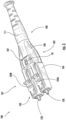
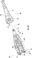
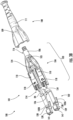
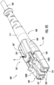
- Optical fiber connector assembly 100 includes a connector 101 having a latch 102, connector subassembly 103, crimp band 106, and a boot assembly 108 each of which are coupled to each other to form optical fiber connector assembly 100.
- Connector 101 is configured to terminate the end of an optical fiber. Connector 101 mechanically couple and align cores of optical fibers so light can pass. As shown, connector 101 is a duplex connector. However, it is contemplated that in alternate embodiments, other suitable connectors may be used such as simplex connectors, for example.
- Latch 102 is configured to assist in coupling optical fiber connector assembly 100 to relevant receiving structures (e.g., receiver modules, etc.).
- Latch 102 is coupled to connector base body 104 where front end 137 of latch 102 is received onto front end 114 of connector base body 104.
- front end 137 includes guide bodies 139 that extend from latch arms 102A, 102B as shown, and guide bodies 139 couple to front end 114 of connector base body 104 as discussed in greater detail below.
- guide bodies 139 are received into recess 113 of connector base body 104 at front end 114 of connector base body 104 such that guide bodies 139 contact front end 114 of connector base body 104 and are contoured to the shape of connector base body 104 at front end 114.
- Guide bodies 139 include apertures 141 that define and extend passages through which ferrules 120 extend when connector 101 is assembled ( FIG. 3 ).
- Latch 102 is also configured to reverse the polarity of the optical fiber connector assembly 100 as discussed in greater detail herein.
- latch 102 includes latch arms 102A, 102B that are joined at a rear end 136 of latch 102 where the rear end 136 includes a rear protrusion 134.
- Latch arms 102A, 102B are generally parallel; however, it is within the scope of the present disclosure that in alternate embodiments, latch arms 102A, 102B are not parallel with each other.
- each latch arm 102A, 102B includes a retention protrusion 138 that engages with connector base body 104 to couple latch 102 onto connector base body 104. Referring briefly to FIGS.
- retention protrusion 138 extends into a window 118 of connector base body 104 and in turn, latches retention protrusion 138 into place on connector base body 104. It is within the scope of the present disclosure, that alternate coupling configurations of latch 102 and connector base body 104 may be used (e.g., frictional engagement, etc.). Additional details regarding installation and removal of latch 102 onto connector base body 104 are discussed in greater detail herein.
- Rear protrusion 134 is configured to latch onto boot assembly 108 (in cut out 107) and provides additional security of latch 102 onto connector base body 104 of connector assembly 100.
- latch 102 is made of polymeric materials such as Ultem ® 1000 as manufactured by SABIC and other suitable materials. However, in alternate embodiments, it is contemplated that other suitable materials may be used for latch 102.
- Connector subassembly 103 includes a connector base body 104, a ferrule 120, and a ferrule holder 122 where connector base body 104 is configured to receive ferrule 120 and ferrule holder 122. Also, as mentioned previously, latch 102 is received onto front end 114 of connector body 104.
- connector base body 104 includes recesses 113 configured to receive guide bodies 139. As shown, connector base body 104 includes routing slots 105, latch arm relief 110, window 118, front end 114, and rear end 116.
- Routing slots 105 are configured to hold fiber guide tubes 112 and optical fiber 130, which is housed within fiber guide tube 112 which extends from a rear end portion of connector base body 104 to within ferrule holder 122 to help guide the insertion of optical fiber 130 ( FIG. 18 ) via fiber guide tubes 112 into ferrule 120. Routing slots 105 lead to recess 129 which receives spring 126. Spring 126 is configured to interact with walls of connector base body 104 to bias ferrule holder 122 and ferrule 120.
- connector base body 104 includes latch arm relief 110.
- Latch arm relief 110 is configured to provide relief to latch arm 102 as applied by boot assembly 108 when removing boot assembly 108 from connector assembly 100 as discussed below.
- Connector base body 104 includes a window 118 near front end 114. Window 118 is adjacent to latch arm relief 110 and provides access to optical fiber 130 as discussed in greater detail herein. However, it is contemplated that in alternate embodiments, connector base body 104 does not include a window 118 and optical fiber 130 is processed prior to insertion into connector base body 104 and ferrule 120.
- Front end 114 of connector base body 104 is configured to receive ferrule 120 and ferrule holder 122.
- a ferrule assembly 125 is shown.
- Ferrule assembly 125 includes ferrule 120 and ferrule holder 122.
- ferrule 120 is received into ferrule holder 122.
- ferrule holder 122 includes a ferrule holder window 123 distal to an end face of ferrule 120.
- ferrule holder window 123 is downstream of an end face of ferrule 120.
- Ferrule holder window 123 provides access to optical fiber 130 that is fed into ferrule 120, and ferrule holder window 123 enables treatment or processing of optical fiber 130 prior to being fed into ferrule 120 as discussed in greater detail herein.
- ferrule assembly 125 is coupled to a clip carrier 128.
- Clip carrier 128 has latch arms 128A, 128B that engage with internal surfaces of connector base body 104 as shown in at least FIGS. 15 and 16 .
- latch arms 128A, 128B engage with connector base body 104 ( FIGS. 15 and 16 ) such that window 118 is aligned with ferrule holder window 123 as shown in FIG. 17 thereby enabling treatment or processing of incoming optical fiber 130 as discussed in greater detail herein.
- window 118 provides access to optical fiber 130 such that laser energy 131 can be administered to optical fiber 130 through window 118.
- laser energy 131 cleaves optical fiber 130 prior to the insertion of cleaved optical fiber 130 into an internal bore 121 of ferrule 120.
- ferrule 120 includes a bonding agent 127 seated on internal bore 121.
- Bonding agent 127 may be pre-loaded or stored within ferrule 120 (e.g., bonding agent 127 may be pre-loaded into the internal bore 121 by the manufacturer of ferrule 120) for a significant amount of time (e.g., at least an hour, a day, a year, etc.) before inserting optical fiber 130 into internal bore 121.
- bonding agent 127 may be a free-flowing powder material coupled within internal bore 121 via compression.
- bonding agent 127 may alternatively be extruded.
- bonding agent 127 is not included in internal bore 121 as discussed below.
- additional laser energy 133 can be administered on or adjacent to the end face of ferrule 120 such that the heat generated by laser energy 133 melts at least a portion of bonding agent 127 and expanding ferrule 120 thereby enabling optical fiber 130 to adhere to ferrule 120.
- ferrule 120 does not include bonding agent 127 within internal bore 121.
- optical fiber 130 ( FIG. 5 ) is inserted directly into ferrule 120 through internal bore 121 such that at least a portion of optical fiber 130 protrudes outwardly from front end of ferrule 120.
- Laser energies 131, 133 can be administered by a laser apparatus (not shown) that is commonly known in the art.
- Rear end 116 of connector base body 104 is configured to receive crimp band 106.
- a fiber optic cable providing optical fiber 130 ( FIG. 18 ) also includes one or more layers of material (e.g., strength layer of aramid yarn) that may be crimped onto rear end 116 of connector base body 104.
- a crimp band (or "crimp ring") 106 may be provided for this purpose.
- a strain-relieving boot e.g., boot assembly 108 may be placed over the crimped region and extend rearwardly to cover a portion of the fiber optic cable. Variations of these aspects will be appreciated by persons familiar with the design of fiber optic cable assemblies. For example, other ways of securing a fiber optic cable to connector base body 104 are also known and may be employed in some embodiments.
- Boot assembly 108 is shown in FIGS. 19 and 20 and is configured to limit radial movement of optical fiber cable and to actuate latch 102 during assembly or disassembly of optical fiber connector assembly 100.
- Boot assembly 108 includes head portion 109 and a tail portion 111 that are coupled together.
- head portion 109 is coupled to tail portion 111 in a snap fit configuration.
- boot assembly 108 could be constructed as an elastomer overmolded onto a boot assembly substrate.
- alternate coupling configurations may be used.
- Boot assembly 108 provides a push pull user experience when assembling and disassembling connector 101 as discussed in greater detail herein.
- boot assembly 108 also includes an aperture 132 within a cut out 107 to receive rear protrusion 134 of latch 102 as discussed in greater detail herein.
- cut out 107 that includes aperture 132 is sized and configured to receive rear protrusion 134 of latch 102 such that rear protrusion can be coupled to boot assembly 108 as discussed in greater detail herein.
- boot assembly 108 provides an advantage of being spatially efficient thereby enabling a high packing density of optical fiber connector assemblies 100 in certain applications (e.g., data centers, etc.).
- optical fiber(s) 130 and ferrule assembly 125 are inserted into connector base body 104 as shown in at least FIG. 11 .
- crimp band 106 is applied onto rear end 116 of connector base body 104.
- Latch 102 is then applied onto connector base body 104 from front end 114 such that retention protrusion 138 of each latch arm 102A, 102B engage with a corresponding arm of connector base body 104, and guide bodies 139 are received into recesses 113 of connector base body 104 such that guide bodies 139 mesh and/or contact with front end 114 of connector base body 104.
- retention protrusion 138 engages with window 118 of connector base body 104.
- Boot assembly 108 is then applied onto connector base body 104 from rear end 116 so that rear protrusion engages with cut out 107 of boot assembly 108.
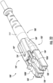
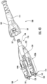
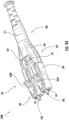
- optical fiber connector assembly 100' Similar to optical fiber connector assembly 100', optical fiber connector assembly 100' includes a connector 101' having a latch 102', connector subassembly 103', crimp band 106', and a boot assembly 108' each of which are coupled to each other to form optical fiber connector assembly 100'.
- Connector 101' is configured to terminate the end of an optical fiber.
- Connector 101' is configured to mechanically couple to an adapter or other receptacle and align cores of optical fibers with those in a mating connector or other device on the opposite side of the receptacle so light can pass.
- connector 101' is a duplex connector.
- other suitable connectors may be used such as simplex connectors, for example.
- latch 102' is shown.
- Latch 102' is configured to assist in coupling optical fiber connector assembly 100' to relevant receiving structures (e.g., receptables/adapters, receiver modules, etc.).
- Latch 102' is coupled to connector base body 104' where front end 137' of latch 102' is received onto front end 114' of connector base body 104'.
- front end 137' includes guide bodies 139' that extend from latch arms 102A', 102B' as shown, and guide bodies 139' couple to front end 114' of connector base body 104' as discussed in greater detail below.
- guide bodies 139' are received into recess 113' of connector base body 104' at front end 114' of connector base body 104' such that guide bodies 139' contact front end 114' of connector base body 104' and are contoured to the shape of connector base body 104' at front end 114'.
- Guide bodies 139' include apertures 141' that define passages through which ferrules 120' extend when connector 101' is assembled ( FIG. 22 ).
- Latch 102' is also configured to reverse the polarity of the optical fiber connector assembly 100' as discussed in greater detail herein. As shown in FIG. 24 , latch 102' includes latch arms 102A', 102B' that are joined at a rear end 136' of latch 102' where the rear end 136' includes a rear protrusion 134'. Latch arms 102A', 102B' are generally parallel; however, it is within the scope of the present disclosure that in alternate embodiments, latch arms 102A', 102B' are not parallel with each other.
- latch 102' also includes a centering member 143' that is configured to be inserted into a centering slot 145' and maintain the positioning of latch 102' when latch 102' is installed onto connector base body 104' to couple latch 102' onto connector base body 104'.
- latch 102' further includes a pair of bowflex arms 147' (also referred to as flex arms 147') extending from rear end 136' and are positioned relative to connector base body 104' by centering member 143' as discussed above. Additional details regarding installation and removal of latch 102' onto connector base body 104' are discussed in greater detail herein.
- Rear protrusion 134' is configured to latch onto boot assembly 108' and provides additional security of latch 102' onto connector base body 104' of connector assembly 100.
- latch 102' is made of polymeric materials such as Ultem ® 1000 as manufactured by SABIC and other suitable materials. However, in alternate embodiments, it is contemplated that other suitable materials may be used for latch 102'.
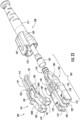
- Connector subassembly 103' includes a connector base body 104', a ferrule 120', and a ferrule holder 122' where connector base body 104' is configured to receive ferrule 120' and ferrule holder 122'. Also, as mentioned previously, latch 102' is received onto front end 114' of connector body 104'.
- connector base body 104' includes recesses 113' configured to receive guide bodies 139'.
- connector base body 104' includes routing slots 105', latch arm relief 110', window 118', front end 114', and rear end 116'.
- Routing slots 105' are configured to hold fiber guide tubes 112' and optical fiber 130 ( FIG. 18 ), which is housed within fiber guide tube 112' which extends from a rear end portion of connector base body 104' to within ferrule holder 122' to help guide the insertion of optical fiber 130 via fiber guide tubes 112' into ferrule 120'. Routing slots 105' lead to recess 129' which receives spring 126'. Spring 126' is configured to interact with walls of connector base body 104' to bias ferrule holder 122' and ferrule 120'.
- connector base body 104' includes latch arm relief 110'.
- Latch arm relief 110' is configured to provide relief to latch arm 102' as applied by boot assembly 108' when removing boot assembly 108' from connector assembly 100' as discussed below.
- Connector base body 104' includes a window 118' near front end 114'. Window 118' is adjacent to latch arm relief 110' and provides access to optical fiber 130 as discussed in greater detail herein. However, it is contemplated that in alternate embodiments, connector base body 104' does not include a window 118' and optical fiber 130 is processed prior to insertion into connector base body 104' and ferrule 120'.
- Front end 114' of connector base body 104' is configured to receive ferrule 120' and ferrule holder 122'.
- a ferrule assembly 125' is shown.
- Ferrule assembly 125' includes ferrule 120' and ferrule holder 122'. As shown, a rear portion of ferrule 120' is received into ferrule holder 122'.
- ferrule holder 122' includes a ferrule holder window 123' distal to a rear end of ferrule 120'. Stated another way, ferrule holder window 123' is downstream of a rear end of ferrule 120'.
- Ferrule holder window 123' provides access to optical fiber 130 that is fed into ferrule 120', and ferrule holder window 123' enables treatment or processing of optical fiber 130 prior to being fed into ferrule 120' as discussed in greater detail herein.
- ferrule assembly 125' is coupled to a clip carrier 128'.
- ferrule assembly 125 may be coupled to clip carrier 128'.
- clip carrier 128' provides a housing structure with an aperture 151' through which a ferrule 120, 120' extends and a receiving area 149' in fluid communication with aperture 151' where receiving area 149' receives ferrule assembly 125, 125'.
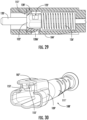
- Clip carrier 128' also has a singular protrusion 128A' along a bottom surface of clip carrier 128' that engages with internal surfaces of connector base body 104' as shown in at least FIG. 29 .
- latch arm 128A' engages with connector base body 104' ( FIG. 29 ) such that window 118' is aligned with ferrule holder window 123' similar to what is shown in FIG. 17 thereby enabling treatment or processing of incoming optical fiber 130 as discussed herein with respect to FIG. 18 .
- optical fiber connector assembly 100' may include a bonding agent 127 as discussed above.
- bonding agent 127 is omitted in this section, and the relevant disclosure of either the presence or absence of bonding agent 127 (and corresponding laser treatments) for optical fiber connector assembly 100 applies to optical fiber connector assembly 100'.
- Rear end 116' of connector base body 104' is configured to receive crimp band 106'.
- a fiber optic cable providing optical fiber 130 ( FIG. 18 ) also includes one or more layers of material (e.g., strength layer of aramid yarn) that may be crimped onto rear end 116' of connector base body 104'.
- a crimp band (or "crimp ring") 106' may be provided for this purpose.
- crimp band 106 is an elongated tube that couples to rear end 116' of connector base body 104' and extends along a length of boot assembly 108' such that crimp band 106' extends beyond the length of boot assembly 108'.
- a strain-relieving boot (e.g., boot assembly 108') may be placed over the crimped region and extend rearwardly to cover a portion of the fiber optic cable. Variations of these aspects will be appreciated by persons familiar with the design of fiber optic cable assemblies. For example, other ways of securing a fiber optic cable to connector base body 104' are also known and may be employed in some embodiments.
- Boot assembly 108' is shown in FIGS. 30-32 and is configured to limit radial movement of optical fiber cable and to actuate latch 102' during assembly or disassembly of optical fiber connector assembly 100'.
- Boot assembly 108' includes head portion 109' and a tail portion 111' that are coupled together, e.g., through a mechanical connector or by way of being integrally formed together as a unitary structure.
- head portion 109' is coupled to tail portion 111' in a snap fit configuration.
- boot assembly 108' could be constructed as an elastomer overmolded onto a boot assembly substrate. However, it is contemplated that in other alternate embodiments, alternate coupling configurations may be used.
- Boot assembly 108' provides a push-pull user experience when assembling and disassembling connector 101' as discussed in greater detail herein.
- boot assembly 108' also includes an aperture 132' within a cut out 107' to receive rear protrusion 134' of latch 102' as discussed in greater detail herein.
- cut out 107' (that includes aperture 132') is sized and configured to receive rear protrusion 134' of latch 102' such that rear protrusion 134' can be coupled to boot assembly 108' as discussed in greater detail herein.
- boot assembly 108' includes a downward protrusion 153' that defines a recess 153' where rear protrusion 134' is received and extends into cut out 107' (that includes aperture 132').
- boot assembly 108' provides an advantage of being spatially efficient thereby enabling a high packing density of optical fiber connector assemblies 100' in certain applications (e.g., data centers, etc.).
- Optical fiber connector assembly 100' may be assembled using steps similar to those described above for optical connector assembly 100. As such, discussion of the steps with respect to optical fiber connector assembly 100' are omitted for the sake of brevity.
- FIGS. 33-44 a method of reversing polarity of optical fiber connector assembly 100 is shown.
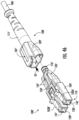
- latch 102 is first disengaged from boot assembly 108.
- a downward force in direction D is applied onto rear end 116 and rear protrusion 134 such that rear protrusion disengages with cut out 107 of boot assembly 108.
- boot assembly is moved along direction D1 to disengage boot assembly from connector base body 104 as shown in FIG. 34 .
- FIG. 34 shows the first disengaged from connector base body 104 as shown in FIG. 34 .
- an upward force D2 is applied onto latch arms 102A, 102B to disengage retention protrusions 138 from connector base body 104 (as shown in FIG. 10 ).
- latch 102 is removed from connector base body 104 by moving latch 102 in a direction D3 as shown in FIG. 36 where guide bodies 139 are removed from recesses 113.
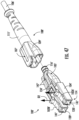
- latch 102 is rotated about 180 degrees relative to a central axis A of latch 102 in either direction R1
- boot assembly 108 is rotated about 180 degrees relative to a central axis A2 in either direction R3 as shown in FIG. 37 . Then, as shown in FIG.
- flipped latch 102 is coupled onto connector subassembly 103 when flipped latch 102 is moved along direction D4 such that flipped latch 102 is re-applied onto connector base body 104 of connector subassembly 103 such that retention protrusions 138 engage with connector base body 104 of connector subassembly 103 and guide bodies 139 are received into recesses 113 such that guide bodies 139 mesh and/or contact with front end 114 of connector base body 104.
- Boot assembly 108 is then coupled to flipped latch 102 and connector subassembly 103 by moving boot assembly 108 along direction D5 as shown in FIG. 39 thereby resulting in an optical fiber connector assembly 100A with a reversed polarity as shown in FIG. 40 .
- boot assembly 108 is applied onto connector base body 104 of connector subassembly 103 from rear end 116 to engage with rear protrusion 134 of flipped latch arm 102 thereby resulting in an optical fiber connector assembly 100A with a reversed polarity as shown in FIG. 40 .
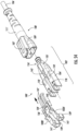
- connector subassembly 103 is rotated about 180 degrees relative to a central axis A1 by moving connector subassembly 103 in either direction R2 as shown in FIG. 41 . Then, as shown in FIG.
- latch 102 is coupled onto flipped connector subassembly 103 when latch 102 is moved along direction D6 such that latch 102 is re-applied onto flipped connector base body 104 of flipped connector subassembly 103 such that retention protrusions 138 engage with flipped connector base body 104 of flipped connector subassembly 103 and guide bodies 139 are received into recesses 113 such that guide bodies 139 mesh and/or contact with front end 114 of connector base body 104.
- Flipped boot assembly 108 are then coupled to latch 102 and flipped connector subassembly 103 by moving flipped boot assembly 108 along direction D7 as shown in FIG.
- flipped boot assembly 108 is applied onto flipped connector base body 104 of flipped connector subassembly 103 from rear end 116 to engage with rear protrusion 134 of latch arm 102 thereby resulting in an optical fiber connector assembly 100A with a reversed polarity as shown in FIG. 44 .
- the polarity reversal process outlined herein enables the polarity of optical fiber connector 101 to be reversed without twisting optical fibers 130.
- FIGS. 45-56 a method of reversing polarity of optical fiber connector assembly 100' is shown.
- latch 102' is first disengaged from boot assembly 108'.
- a downward force in direction D is applied onto rear end 116' and rear protrusion 134' such that rear protrusion disengages with cut out 107' of boot assembly 108'.
- boot assembly is moved along direction D1 to disengage boot assembly from connector base body 104' as shown in FIG. 46 . Then, as shown in FIG.
- latch 102' is removed from connector base body 104' by moving latch 102' in a direction D3 as shown in FIG. 48 where guide bodies 139' are removed from recesses 113'.
- latch 102' is rotated about 180 degrees relative to a central axis A of latch 102' in either direction R1
- boot assembly 108' is rotated about 180 degrees relative to a central axis A2 in either direction R3 as shown in FIG. 49 . Then, as shown in FIG.
- flipped latch 102' is coupled onto connector subassembly 103' when flipped latch 102' is moved along direction D4 such that flipped latch 102' is re-applied onto connector base body 104' of connector subassembly 103' such that retention protrusions 138' engage with connector base body 104' of connector subassembly 103' and guide bodies 139' are received into recesses 113' such that guide bodies 139' mesh and/or contact with front end 114' of connector base body 104'.
- Boot assembly 108' is then coupled to flipped latch 102' and connector subassembly 103' by moving boot assembly 108' along direction D5 as shown in FIG.
- boot assembly 108' is applied onto connector base body 104' of connector subassembly 103' from rear end 116' to engage with rear protrusion 134' of flipped latch arm 102' thereby resulting in an optical fiber connector assembly 100A' with a reversed polarity as shown in FIG. 52 .
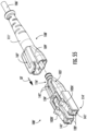
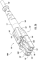
- connector subassembly 103' is rotated about 180 degrees relative to a central axis A1 by moving connector subassembly 103' in either direction R2 as shown in FIG. 53 . Then, as shown in FIG.
- latch 102' is coupled onto flipped connector subassembly 103' when latch 102' is moved along direction D6 such that latch 102' is re-applied onto flipped connector base body 104' of flipped connector subassembly 103' such that retention protrusions 138' engage with flipped connector base body 104' of flipped connector subassembly 103' and guide bodies 139' are received into recesses 113' such that guide bodies 139' mesh and/or contact with front end 114' of connector base body 104'.
- Flipped boot assembly 108' are then coupled to latch 102' and flipped connector subassembly 103' by moving flipped boot assembly 108' along direction D7 as shown in FIG.
- flipped boot assembly 108' is applied onto flipped connector base body 104' of flipped connector subassembly 103' from rear end 116' to engage with rear protrusion 134' of latch arm 102' thereby resulting in an optical fiber connector assembly 100A' with a reversed polarity as shown in FIG. 56 .
- the polarity reversal process outlined herein enables the polarity of optical fiber connector 101' to be reversed without twisting optical fibers 130'.
Landscapes
- Physics & Mathematics (AREA)
- General Physics & Mathematics (AREA)
- Optics & Photonics (AREA)
- Mechanical Coupling Of Light Guides (AREA)
Applications Claiming Priority (1)
| Application Number | Priority Date | Filing Date | Title |
|---|---|---|---|
| US202263315642P | 2022-03-02 | 2022-03-02 |
Publications (2)
| Publication Number | Publication Date |
|---|---|
| EP4239383A2 true EP4239383A2 (de) | 2023-09-06 |
| EP4239383A3 EP4239383A3 (de) | 2023-11-15 |
Family
ID=85410454
Family Applications (1)
| Application Number | Title | Priority Date | Filing Date |
|---|---|---|---|
| EP23159232.0A Withdrawn EP4239383A3 (de) | 2022-03-02 | 2023-02-28 | Optischer verbinder mit veränderbarer polarität |
Country Status (2)
| Country | Link |
|---|---|
| US (1) | US12560765B2 (de) |
| EP (1) | EP4239383A3 (de) |
Families Citing this family (2)
| Publication number | Priority date | Publication date | Assignee | Title |
|---|---|---|---|---|
| EP3729154B1 (de) * | 2017-12-19 | 2025-02-12 | US Conec, Ltd | Mini-duplex-verbinder mit gegentaktpolaritätsmechanismus und träger |
| US12560765B2 (en) * | 2022-03-02 | 2026-02-24 | Corning Research & Development Corporation | Polarity changeable optical connector |
Citations (5)
| Publication number | Priority date | Publication date | Assignee | Title |
|---|---|---|---|---|
| US6565262B2 (en) | 2000-12-14 | 2003-05-20 | Corning Cable Systems Llc | Trigger mechanism, optical cable connector including same, and method of assembling an optical cable connector |
| US20080226237A1 (en) | 2007-03-15 | 2008-09-18 | O'riorden Stephen | Single boot for duplex fiber optic connectors |
| US8696215B1 (en) | 2012-10-15 | 2014-04-15 | Corning Cable Systems Llc | Adhesive compositions including partially cross-linked resins and coupling agents and methods for use thereof |
| US8702322B1 (en) | 2013-06-03 | 2014-04-22 | Corning Cable Systems Llc | Optical connector with adhesive material |
| US9568686B2 (en) | 2012-10-15 | 2017-02-14 | Corning Optical Communications LLC | Optical connector and ferrule adhesion system including adhesive composition, and related methods |
Family Cites Families (99)
| Publication number | Priority date | Publication date | Assignee | Title |
|---|---|---|---|---|
| US5579425A (en) | 1995-08-30 | 1996-11-26 | Lucent Technologies Inc. | Anti-snag duplex connector |
| US7150567B1 (en) | 2005-05-27 | 2006-12-19 | Corning Cable Systems Llc | Fiber optic connector having keyed ferrule holder |
| EP2664951B1 (de) | 2008-05-07 | 2016-06-15 | Huber + Suhner Ag | Steckverbinder mit Entriegelung |
| US20100080517A1 (en) | 2008-09-29 | 2010-04-01 | Cline Timothy S | Fiber optic connector assembly employing fiber movement support and method of assembly |
| US7712970B1 (en) | 2009-01-12 | 2010-05-11 | Alliance Fiber Optic Products Co., Ltd. | Detachable fiber optic connector |
| GB2468188B (en) | 2009-02-26 | 2011-05-11 | Advanced Fiber Products Ltd | Fibre optic connector assembly |
| US8152385B2 (en) | 2009-02-27 | 2012-04-10 | Corning Cable Systems Llc | Duplex fiber optic assemblies suitable for polarity reversal and methods therefor |
| US8152384B2 (en) | 2009-10-15 | 2012-04-10 | Corning Cable Systems Llc | Push-pull fiber optic connectors and methods for making the same |
| JP4995305B2 (ja) | 2010-06-04 | 2012-08-08 | サンコール株式会社 | 2芯型光コネクタユニット |
| US8662760B2 (en) | 2010-10-29 | 2014-03-04 | Corning Cable Systems Llc | Fiber optic connector employing optical fiber guide member |
| JP2012128341A (ja) | 2010-12-17 | 2012-07-05 | Suncall Corp | 二芯型光コネクタ |
| WO2012151175A2 (en) | 2011-05-04 | 2012-11-08 | The Siemon Company | Fiber optic connector with polarity change |
| US8764308B2 (en) | 2011-06-06 | 2014-07-01 | Panduit Corp. | Duplex clip assembly for fiber optic connectors |
| US8727638B2 (en) | 2011-12-21 | 2014-05-20 | Alliance Fiber Optic Products Co., Ltd. | Fiber channel-inter changeable fiber optic connector |
| CN103257407B (zh) | 2012-02-20 | 2015-11-25 | 泰科电子(上海)有限公司 | 连接器和连接器组件 |
| US8678669B2 (en) | 2012-08-14 | 2014-03-25 | Alliance Fiber Optic Products Co., Ltd. | Reconfigurable polarity detachable connector assembly |
| GB2506884B (en) | 2012-10-10 | 2017-04-12 | Fibrefab Ltd | Fibre optic connector device |
| US9297976B2 (en) | 2012-11-14 | 2016-03-29 | Clearfield, Inc. | Optical fiber connector |
| EP2759859B1 (de) | 2013-01-29 | 2018-05-16 | Tyco Electronics Nederland B.V. | Führungsstütze und Kit zum Abschließen eines Übertragungskabels |
| CN203965665U (zh) | 2013-03-06 | 2014-11-26 | 中航光电科技股份有限公司 | 双工lc插头 |
| TWM474924U (zh) | 2013-09-27 | 2014-03-21 | Fiberon Technologies Inc | 具空間角位置換之光學連接器 |
| US9207410B2 (en) | 2013-12-23 | 2015-12-08 | Alliance Fiber Optic Products, Inc. | Optical fiber connector assembly |
| EP3095000B1 (de) | 2014-01-13 | 2021-04-28 | CommScope Telecommunications (Shanghai) Co. Ltd. | Faseroptischer verbinder |
| CN104808296B (zh) | 2014-01-28 | 2016-08-17 | 智英科技股份有限公司 | 双工光纤连接器插头 |
| CN203720408U (zh) | 2014-02-11 | 2014-07-16 | 智英科技股份有限公司 | 追踪跳线结构 |
| CN203786336U (zh) | 2014-03-06 | 2014-08-20 | 深圳市嘉万光通信有限公司 | 一种一体式lc双芯光纤连接器 |
| US9791637B2 (en) | 2014-04-21 | 2017-10-17 | Corning Optical Communications LLC | Methods of terminating one or more optical fibers |
| US10495824B2 (en) | 2014-05-16 | 2019-12-03 | Joel C. Rosson | Optical connector element |
| JP6434742B2 (ja) | 2014-08-13 | 2018-12-05 | 三和電気工業株式会社 | 2芯型光コネクタプラグ |
| US9599778B2 (en) | 2014-10-22 | 2017-03-21 | Senko Advanced Components, Inc. | Latching connector with remote release |
| WO2016082160A1 (zh) | 2014-11-27 | 2016-06-02 | 新确精密科技(深圳)有限公司 | 一种lc双联连接器 |
| GB2538089B (en) | 2015-05-06 | 2019-06-19 | Fibrefab Ltd | Fibre optic cable assembly |
| US9739955B2 (en) | 2015-05-07 | 2017-08-22 | Alliance Fiber Optic Products, Inc. | Push-pull type fiber optic connector assembly |
| US9678283B1 (en) | 2016-01-15 | 2017-06-13 | Senko Advanced Components, Inc. | Fiber optic connector assemblies with adjustable polarity |
| US9595786B1 (en) | 2016-01-15 | 2017-03-14 | Senko Advanced Components, Inc. | Narrow width adapters and connectors with spring loaded remote release |
| US10158194B2 (en) | 2016-01-15 | 2018-12-18 | Senko Advanced Components, Inc. | Narrow width adapters and connectors with spring loaded remote release |
| US9933584B2 (en) | 2016-02-03 | 2018-04-03 | Jyh Eng Technology Co., Ltd. | Duplex fiber optic connector plug with angles actuated latching |
| US9946035B2 (en) | 2016-04-11 | 2018-04-17 | Leviton Manufacturing Co., Inc. | Fiber optic connector |
| EP3469410B1 (de) | 2016-06-13 | 2021-10-27 | Corning Optical Communications LLC | Verbinder mit auslöserarretierungsfunktion und kabelanordnungen und verfahren damit |
| DE202016103178U1 (de) | 2016-06-16 | 2016-07-07 | Reichle & De-Massari Ag | Steckverbinder |
| JP6173629B1 (ja) | 2016-06-29 | 2017-08-02 | 株式会社精工技研 | 二連式の光コネクタプラグ及び二連式の光コネクタプラグの極性変換方法並びにフェルール研磨方法 |
| US10162129B2 (en) | 2016-08-19 | 2018-12-25 | Ortronics, Inc. | Internal harnessing members and method for bend control of optical fibers in connector assemblies |
| CN106383383B (zh) | 2016-11-01 | 2019-02-15 | 南京普天天纪楼宇智能有限公司 | 一种一缆双芯lc型光纤连接器 |
| US10228521B2 (en) | 2016-12-05 | 2019-03-12 | Senko Advanced Components, Inc. | Narrow width adapters and connectors with modular latching arm |
| US10078188B1 (en) | 2016-12-05 | 2018-09-18 | Senko Advanced Components, Inc. | Springless push/pull fiber optic connector |
| US10185100B2 (en) | 2017-01-30 | 2019-01-22 | Senko Advanced Components, Inc | Modular connector and adapter assembly using a removable anchor device |
| CN113156586B (zh) | 2017-01-30 | 2026-05-05 | 扇港元器件股份有限公司 | 具有可逆极性的光学连接器 |
| US20190391343A1 (en) | 2017-01-31 | 2019-12-26 | Sei Optifrontier Co., Ltd. | Optical connector and optical fiber with connector |
| CN206696473U (zh) | 2017-04-17 | 2017-12-01 | 深圳市飞博康光通讯技术有限公司 | 一种lc双联连接器 |
| CN106918869B (zh) | 2017-04-17 | 2018-10-26 | 深圳市飞博康光通讯技术有限公司 | 一种lc双联连接器 |
| US10663676B2 (en) | 2017-05-25 | 2020-05-26 | Senko Advanced Components, Inc | Adjustable polarity fiber optic connector assemblies with push-pull tabs |
| US10620384B2 (en) | 2017-05-25 | 2020-04-14 | Senko Advanced Components, Inc. | Adjustable polarity fiber optic connector assemblies with push-pull tabs |
| US9941631B1 (en) | 2017-06-29 | 2018-04-10 | Seikoh Giken Co., Ltd. | Plug and cable with plug |
| CN107132623B (zh) | 2017-07-10 | 2023-08-08 | 广东亿源通科技股份有限公司 | 一种光纤连接器 |
| US10281669B2 (en) | 2017-07-14 | 2019-05-07 | Senko Advance Components, Inc. | Ultra-small form factor optical connectors |
| TWM552602U (zh) | 2017-07-20 | 2017-12-01 | 建毅科技股份有限公司 | 光纖連接器 |
| US11002923B2 (en) | 2017-11-21 | 2021-05-11 | Senko Advanced Components, Inc. | Fiber optic connector with cable boot release having a two-piece clip assembly |
| US10712512B2 (en) | 2017-11-21 | 2020-07-14 | Senko Advanced Components, Inc | Fiber optic connector assemblies with cable boot release |
| US10539747B2 (en) * | 2017-12-05 | 2020-01-21 | Corning Research & Development Corporation | Bend induced light scattering fiber and cable assemblies and method of making |
| EP3729154B1 (de) | 2017-12-19 | 2025-02-12 | US Conec, Ltd | Mini-duplex-verbinder mit gegentaktpolaritätsmechanismus und träger |
| US10634854B2 (en) | 2018-01-03 | 2020-04-28 | Afl Ig Llc | Push-pull boot connector for fiber optic cables |
| CN207965232U (zh) | 2018-04-04 | 2018-10-12 | 乐清市欧亚华通讯设备有限公司 | 一种可换极性lc双联连接器 |
| US10962732B2 (en) | 2018-05-03 | 2021-03-30 | Senko Advanced Components, Inc. | Flexible boot with replacable repositioning device therein |
| US11409054B2 (en) | 2018-05-11 | 2022-08-09 | Us Conec Ltd. | Method and apparatus for assembling uniboot fiber optic connectors |
| JP7160959B2 (ja) | 2018-06-28 | 2022-10-25 | センコー アドバンスド コンポーネンツ インコーポレイテッド | 短縮された回転可能ブーツアセンブリを備えた極性調節可能な光ファイバコネクタアセンブリ |
| WO2020013059A1 (ja) | 2018-07-13 | 2020-01-16 | 株式会社フジクラ | 光コネクタ、光コネクタ付き光ファイバケーブルの製造方法及び光ファイバ接続用工具 |
| JP2020016698A (ja) | 2018-07-23 | 2020-01-30 | 株式会社フジクラ | 光コネクタ、及び、ラッチ解除部材 |
| US10444441B1 (en) | 2018-08-10 | 2019-10-15 | Senko Advanced Components, Inc. | Pivotable housing for a fiber optic connector |
| CN112840257A (zh) | 2018-09-11 | 2021-05-25 | 扇港元器件股份有限公司 | 具有整体固定器和插芯保持器的lc单件前部装载的插芯 |
| US11194101B2 (en) | 2018-09-11 | 2021-12-07 | Senko Advanced Components, Inc. | LC one piece front loaded ferrule with unitary retainer and ferrule holder |
| US11454767B2 (en) | 2018-10-10 | 2022-09-27 | Senko Advanced Components, Inc. | Multi-polarity fiber optic connector having a duplex cable boot assembly |
| CN209281010U (zh) | 2019-02-21 | 2019-08-20 | 藤仓(上海)通信器材有限公司 | 用于高密度配线的lc连接器跳线 |
| CN209858786U (zh) | 2019-05-16 | 2019-12-27 | 深圳市飞博康光通讯技术有限公司 | 一种lc双联连接器 |
| CN114026480B (zh) | 2019-06-13 | 2023-05-26 | 扇港元器件有限公司 | 用于从插座端口释放光纤连接器的杆驱动闩锁臂和使用方法 |
| CN210835337U (zh) | 2019-10-22 | 2020-06-23 | 深圳市夏裕精密部件有限公司 | 一种光纤连接器 |
| US20210141162A1 (en) | 2019-11-11 | 2021-05-13 | Senko Advanced Components, Inc. | Fiber optic connector having efficient construction |
| US11385417B2 (en) | 2019-11-15 | 2022-07-12 | Seikoh Giken Co., Ltd. | Connector plug and stopper for connector plug |
| JP7365931B2 (ja) | 2020-02-19 | 2023-10-20 | 住友電工オプティフロンティア株式会社 | 光コネクタ |
| TWI758684B (zh) | 2020-02-20 | 2022-03-21 | 立佳興業股份有限公司 | 解扣機構及使用該機構之光學連接器 |
| TWI747170B (zh) | 2020-02-20 | 2021-11-21 | 立佳興業股份有限公司 | 光學連接器 |
| JP6812037B1 (ja) | 2020-03-05 | 2021-01-13 | 株式会社精工技研 | コネクタプラグ用治具、コネクタプラグ、コネクタプラグ付きケーブル |
| JP6892710B1 (ja) | 2020-03-11 | 2021-06-23 | 株式会社精工技研 | 二連式の光コネクタプラグ |
| US11409056B2 (en) | 2020-03-27 | 2022-08-09 | Afl Ig Llc | Optical fiber connectors and methods of connecting optical fibers |
| US11573381B2 (en) | 2020-03-27 | 2023-02-07 | Afl Telecommunications Llc | Optical fiber connectors and methods of connecting optical fibers |
| CN111399134A (zh) | 2020-04-23 | 2020-07-10 | 中航光电科技股份有限公司 | 一种双工插头 |
| CN211905777U (zh) | 2020-05-09 | 2020-11-10 | 南京华脉科技股份有限公司 | 一种双工lc型光纤活动连接器 |
| CN213876106U (zh) | 2020-12-06 | 2021-08-03 | 上海天诚通信技术股份有限公司 | 一种lc连接器单体底座 |
| CN213876108U (zh) | 2020-12-06 | 2021-08-03 | 上海天诚通信技术股份有限公司 | 一种lc连接器 |
| CN213876107U (zh) | 2020-12-06 | 2021-08-03 | 上海天诚通信技术股份有限公司 | 一种lc连接器外壳 |
| CN214225500U (zh) | 2021-01-14 | 2021-09-17 | 上海天诚通信技术股份有限公司 | 一种高密度易插拔lc连接器 |
| CN214225498U (zh) | 2021-01-14 | 2021-09-17 | 上海天诚通信技术股份有限公司 | 一种极性翻转的易插拔lc连接器 |
| CN214225494U (zh) | 2021-01-14 | 2021-09-17 | 上海天诚通信技术股份有限公司 | 一种极性翻转的高密度拉杆易插拔lc连接器 |
| CN214225497U (zh) | 2021-01-14 | 2021-09-17 | 上海天诚通信技术股份有限公司 | 一种带锁易插拔lc连接器 |
| CN214225495U (zh) | 2021-01-14 | 2021-09-17 | 上海天诚通信技术股份有限公司 | 一种高密度拉杆易插拔lc连接器 |
| CN214225499U (zh) | 2021-01-14 | 2021-09-17 | 上海天诚通信技术股份有限公司 | 一种极性翻转的高密度易插拔lc连接器 |
| CN214225496U (zh) | 2021-01-14 | 2021-09-17 | 上海天诚通信技术股份有限公司 | 一种易插拔lc连接器 |
| US11934017B2 (en) * | 2021-03-02 | 2024-03-19 | Corning Research & Development Corporation | Polarity changeable optical connector |
| US12560765B2 (en) * | 2022-03-02 | 2026-02-24 | Corning Research & Development Corporation | Polarity changeable optical connector |
| EP4581412A1 (de) * | 2022-08-29 | 2025-07-09 | Corning Research & Development Corporation | Optischer verbinder mit drehbarem mantel und zugehörige verfahren |
-
2023
- 2023-02-21 US US18/111,927 patent/US12560765B2/en active Active
- 2023-02-28 EP EP23159232.0A patent/EP4239383A3/de not_active Withdrawn
Patent Citations (5)
| Publication number | Priority date | Publication date | Assignee | Title |
|---|---|---|---|---|
| US6565262B2 (en) | 2000-12-14 | 2003-05-20 | Corning Cable Systems Llc | Trigger mechanism, optical cable connector including same, and method of assembling an optical cable connector |
| US20080226237A1 (en) | 2007-03-15 | 2008-09-18 | O'riorden Stephen | Single boot for duplex fiber optic connectors |
| US8696215B1 (en) | 2012-10-15 | 2014-04-15 | Corning Cable Systems Llc | Adhesive compositions including partially cross-linked resins and coupling agents and methods for use thereof |
| US9568686B2 (en) | 2012-10-15 | 2017-02-14 | Corning Optical Communications LLC | Optical connector and ferrule adhesion system including adhesive composition, and related methods |
| US8702322B1 (en) | 2013-06-03 | 2014-04-22 | Corning Cable Systems Llc | Optical connector with adhesive material |
Also Published As
| Publication number | Publication date |
|---|---|
| US12560765B2 (en) | 2026-02-24 |
| US20230280541A1 (en) | 2023-09-07 |
| EP4239383A3 (de) | 2023-11-15 |
Similar Documents
| Publication | Publication Date | Title |
|---|---|---|
| US10451830B2 (en) | Fiber optic cable assembly and fabrication method using sequentially arranged boots for multi-fiber ferrule | |
| US11934017B2 (en) | Polarity changeable optical connector | |
| US10884196B2 (en) | Optical ferrule for multi-fiber cable and hardened multi-fiber optic connector therefore | |
| US11561357B2 (en) | Fiber optic connection modules | |
| US6421493B1 (en) | Apparatus and method for assembling and aligning a plurality of optical fibers | |
| US9494744B2 (en) | Fiber optic connector having a main connector body and a plurality of removable sub-connectors | |
| EP2312354B1 (de) | Mehrfaseroptische Steckdosen- und Steckeranordnung | |
| US6454464B1 (en) | Fiber optic connectors and transceiver test devices | |
| AU707686B2 (en) | Optical connector with immovable ferrule | |
| US6173097B1 (en) | Field installable multifiber connector | |
| US12560765B2 (en) | Polarity changeable optical connector | |
| WO2000031575A1 (en) | Fiber optic adapter, including hybrid connector system | |
| CN1050616A (zh) | 双工式光纤连接器及与其端接的光缆 | |
| US20170184800A1 (en) | Ferrule for multi-fiber optical connector | |
| EP3948376A1 (de) | Faseroptischer adapterhalter; anordnung und verfahren | |
| US5870515A (en) | Receptacle and associated method for permitting the selective withdrawal of a ferrule | |
| US20250044527A1 (en) | Polarity scheme for multi-fiber connectors with a connector key | |
| US20190285812A1 (en) | Sc low profile connector | |
| US10641972B2 (en) | Anti-jam alignment sleeve holder or connector housing for a ferrule assembly | |
| WO2020181106A2 (en) | Bifurcated housing for securing one or more fiber optic adapter assemblies therein | |
| CN114746786A (zh) | 光学连接器组件 | |
| US11640032B1 (en) | Splice-on fiber optic connector holder | |
| HK1140026B (en) | Multi-fiber fiber optic receptacle and plug assembly |
Legal Events
| Date | Code | Title | Description |
|---|---|---|---|
| PUAI | Public reference made under article 153(3) epc to a published international application that has entered the european phase |
Free format text: ORIGINAL CODE: 0009012 |
|
| STAA | Information on the status of an ep patent application or granted ep patent |
Free format text: STATUS: THE APPLICATION HAS BEEN PUBLISHED |
|
| AK | Designated contracting states |
Kind code of ref document: A2 Designated state(s): AL AT BE BG CH CY CZ DE DK EE ES FI FR GB GR HR HU IE IS IT LI LT LU LV MC ME MK MT NL NO PL PT RO RS SE SI SK SM TR |
|
| PUAL | Search report despatched |
Free format text: ORIGINAL CODE: 0009013 |
|
| AK | Designated contracting states |
Kind code of ref document: A3 Designated state(s): AL AT BE BG CH CY CZ DE DK EE ES FI FR GB GR HR HU IE IS IT LI LT LU LV MC ME MK MT NL NO PL PT RO RS SE SI SK SM TR |
|
| RIC1 | Information provided on ipc code assigned before grant |
Ipc: G02B 6/38 20060101AFI20231006BHEP |
|
| STAA | Information on the status of an ep patent application or granted ep patent |
Free format text: STATUS: THE APPLICATION IS DEEMED TO BE WITHDRAWN |
|
| 18D | Application deemed to be withdrawn |
Effective date: 20240516 |