EP4239336B1 - Verfahren zum herstellen einer mikrotiterplatte mit fängermolekülbeschichtungen und mikrotiterplatte - Google Patents
Verfahren zum herstellen einer mikrotiterplatte mit fängermolekülbeschichtungen und mikrotiterplatte Download PDFInfo
- Publication number
- EP4239336B1 EP4239336B1 EP22160018.2A EP22160018A EP4239336B1 EP 4239336 B1 EP4239336 B1 EP 4239336B1 EP 22160018 A EP22160018 A EP 22160018A EP 4239336 B1 EP4239336 B1 EP 4239336B1
- Authority
- EP
- European Patent Office
- Prior art keywords
- membrane
- segment
- carrier
- segments
- blot
- Prior art date
- Legal status (The legal status is an assumption and is not a legal conclusion. Google has not performed a legal analysis and makes no representation as to the accuracy of the status listed.)
- Active
Links
Images




Classifications
-
- G—PHYSICS
- G01—MEASURING; TESTING
- G01N—INVESTIGATING OR ANALYSING MATERIALS BY DETERMINING THEIR CHEMICAL OR PHYSICAL PROPERTIES
- G01N33/00—Investigating or analysing materials by specific methods not covered by groups G01N1/00 - G01N31/00
- G01N33/48—Biological material, e.g. blood, urine; Haemocytometers
- G01N33/50—Chemical analysis of biological material, e.g. blood, urine; Testing involving biospecific ligand binding methods; Immunological testing
- G01N33/53—Immunoassay; Biospecific binding assay; Materials therefor
- G01N33/543—Immunoassay; Biospecific binding assay; Materials therefor with an insoluble carrier for immobilising immunochemicals
- G01N33/54366—Apparatus specially adapted for solid-phase testing
-
- B—PERFORMING OPERATIONS; TRANSPORTING
- B01—PHYSICAL OR CHEMICAL PROCESSES OR APPARATUS IN GENERAL
- B01J—CHEMICAL OR PHYSICAL PROCESSES, e.g. CATALYSIS OR COLLOID CHEMISTRY; THEIR RELEVANT APPARATUS
- B01J2219/00—Chemical, physical or physico-chemical processes in general; Their relevant apparatus
- B01J2219/00274—Sequential or parallel reactions; Apparatus and devices for combinatorial chemistry or for making arrays; Chemical library technology
- B01J2219/00583—Features relative to the processes being carried out
- B01J2219/00603—Making arrays on substantially continuous surfaces
-
- B—PERFORMING OPERATIONS; TRANSPORTING
- B01—PHYSICAL OR CHEMICAL PROCESSES OR APPARATUS IN GENERAL
- B01L—CHEMICAL OR PHYSICAL LABORATORY APPARATUS FOR GENERAL USE
- B01L2300/00—Additional constructional details
- B01L2300/08—Geometry, shape and general structure
- B01L2300/0809—Geometry, shape and general structure rectangular shaped
- B01L2300/0829—Multi-well plates; Microtitration plates
-
- G—PHYSICS
- G01—MEASURING; TESTING
- G01N—INVESTIGATING OR ANALYSING MATERIALS BY DETERMINING THEIR CHEMICAL OR PHYSICAL PROPERTIES
- G01N2474/00—Immunochemical assays or immunoassays characterised by detection mode or means of detection
- G01N2474/10—Immunoblots, e.g. Western blot or Dot blot
Definitions
- the invention relates to a method for producing a microtiter plate with capture molecule coatings.
- the invention further relates to a microtiter plate with capture molecule coatings in the form of blot line segments in at least one well.
- the invention further relates to a method in which a microtiter plate according to the invention is used for incubation.
- the invention further relates to a digital image processing method.
- catcher molecules in the sense of this application are antigen molecules or antibody molecules.
- capture molecules can also be referred to as antigens or antibodies.
- antigens also includes so-called allergens.
- test systems are known that are used to check the presence of special antibodies in patient samples. Since antibodies are formed in a patient's body after a viral or bacterial infectious disease, such tests can be used to diagnose acute illnesses or illnesses that the patient has already experienced. Autoimmune diseases or allergies can also be diagnosed if appropriate antigens are selected.
- immunoblot strips In the field of in vitro diagnostics, immunoblot strips, especially line blot strips, are often used to establish the diagnosis.
- the immunoblot strips required in each case are usually placed in incubation channels provided for this purpose, in which they are incubated with the required reagents and the patient sample. After a correct test has been carried out, special discolorations, the so-called bands, appear on the immunoblot strips of patient samples that tested positive, which in particular shows the binding of antibodies to the antigens provided on the immunoblot strips.
- the incubated immunoblot strips can be evaluated either by visual inspection or the immunoblot strips are evaluated using automated or at least partially automated systems.
- EU-ROBlotOne system from the company EUROIMMUN Medizinische Labordiagnostika AG is known, which takes pictures of incubated immunoblot strips while the strips are still in the incubation grooves of an incubation tray. The corresponding recordings will be further, if necessary, digitized, transferred to a data evaluation unit and evaluated there with the help of special laboratory software.
- the appearance of the bands and the discoloration of the individual bands in comparison to the background are first determined in preparation for creating a diagnosis proposal. Strongly positive samples regularly result in strong discoloration on the immunoblot strips, while only weakly positive samples often only provide weak signals that may be difficult to evaluate.
- the immunoblot principle uses antigens on membranes as a solid phase to detect specific antibodies in patient samples using an enzymatic color reaction. It is carried out manually, partially or fully automated. If a sample contains specific antibodies, these bind to the membrane-bound antigens.
- a conjugate is added, which is preferably an alkaline phosphatase (AP)-labeled antibody, which in turn binds to the specific antibodies.
- the conjugate catalyzes a color reaction with a subsequently added substrate.
- the substrate is preferably nitroblue tetrazolium chloride/5-bromo-4-chloro-3-indolyl phosphate (NBT/BCIP).
- a discoloration or a dark line appears at the respective antigen position as a so-called band.
- the intensity of the resulting color is proportional to the antibody concentration in the sample. Such colorations can then preferably be recorded and, if necessary, evaluated using digital image processing.
- Line blot strips with several, different antigens are so-called multi-parameter line blots and enable the creation of extensive combined antibody profiles on one test strip.
- Membrane strips with several purified, biochemically characterized antigens or antigen extracts are used as the antigen-containing solid phase, which are applied as thin parallel lines or blot lines on the line blot strip or the membrane strip.
- antibody coatings can be provided as capture molecule coatings on a line blot strip in order to determine whether antigens bind to antibodies.
- capture molecule coatings in the form of antibody coatings can be provided.
- a capture molecule line can also be referred to as a blot line, which in particular has antigens or antibodies.
- microtiter plate made of glass with wells, the well bottom having a coating with holes therein into which antigen spots are introduced directly.
- Such microtiter plates then have several depressions or wells, in each of which several antigen spots are present. Binding of antibodies to the antigen spots located on the bottom of the well can then be detected during incubation with a patient sample, a conjugate and a substrate.
- the object of the present invention is to provide a microtiter plate with capture molecule coatings, which is particularly simple and practical to produce.
- a further advantage may be to provide a microtiter plate whose capture molecule coatings can be optically evaluated efficiently and reliably using a digital image processing method.
- the object according to the invention is achieved by a method according to the invention for producing a microtiter plate with capture molecule coatings, a microtiter plate according to the invention and a method according to the invention in which a microtiter plate according to the invention is used, as well as a digital image processing method according to the invention.
- An exemplary microtiter plate MT is in the Figure 1 shown.
- FIGS. 2A to 2E illustrate the method according to the invention for producing a microtiter plate with capture molecule coatings. The procedure involves various steps.
- a first carrier membrane M1 is provided.
- a second carrier membrane M2 is also provided.
- the first carrier membrane M2 is coated with respective first blot lines BL11, ..., BL14, which can also be referred to as a first set of blot lines BL1.
- the respective first blot lines BL11, ..., BL14 each have a respective capture molecule type. These respective capture molecule types can be different.
- the carrier membrane M1 is coated with the blot lines BL1 by moving several dispensing capillaries or dispensing needles D along an application direction or coating direction AR.
- the dispensing needles D are guided over the membrane M1 in the application direction AR.
- the movement is in particular a linear movement.
- a first membrane segment MS1, which is in the Figure 2A is indicated by a dashed line, from the first carrier membrane M1.
- the membrane segment MS1 then has respective line sections LA11,..., LA14 of the respective first blot lines BL11,..., BL14, as in the Figure 2C shown.
- a line section can also be referred to as a line segment or a blot line segment.
- a second membrane segment MS2 is separated from the second carrier membrane M2.
- the second membrane segment MS2 has respective line sections LA21, ..., LA23 of the respective second blot lines BL21, ..., BL23.
- membrane segments MS11 and MS21 can preferably be separated from the membranes M1 and M2.
- the first membrane segment MS1 is also positioned and fixed on a carrier layer T and the second membrane segment MS2 is positioned and fixed on the carrier layer T.
- the membrane segment MS11 is also positioned and fixed on the carrier layer T and the membrane segment MS11 is also positioned and fixed Membrane segment MS21 on the carrier layer T.
- the membrane segment MS11 is also positioned and fixed on the carrier layer T and the membrane segment MS21 is positioned and fixed on the carrier layer T in on the carrier layer, in particular on a further region TS2, which preferably forms a further carrier layer segment.
- the dashed circle line TS in the Figure 2C indicates a carrier layer segment which is separated from the carrier layer and which has the first and second membrane segments MS1, MS2.
- the carrier layer segment TS is also positioned and fixed in a well W of a microtiter plate.
- Figure 2D shows the well wall WW and the carrier layer segment TS from a top view, so that the carrier layer TS is visible from the opening of the well W.
- the Figure 2E illustrates in the side sectional view of the well W the position of the carrier layer segment TS with the membrane segments MS1, MS2 located thereon above the well bottom WB and between the well walls WW.
- the carrier layer segment TS is positioned and fixed in the well W in particular in such a way that the membrane segments MS1, MS2 are visible from the opening OF the well.
- Fixing the membrane segments or fixing the carrier layer segment can preferably be referred to as mechanical fixing.
- the membrane segments can preferably also be referred to as carrier membrane segments.
- the first blot lines BL1 on the carrier membrane M1 are blocked with a first blocking buffer.
- this also takes place after the second carrier membrane has been coated M2 with the second blot lines BL2 blocking the second blot lines BL2 on the second carrier membrane M2 with a second blocking buffer, which in particular can be a different blocking buffer than the first blocking buffer.
- the first line segments LA11, ..., LA13 are therefore preferably blocked with the first blocking buffer and the second line segments are blocked with the second blocking buffer.
- the method according to the invention has the advantage that a plurality of capture molecule coatings can be introduced or positioned above the well bottom of the well of a microtiter plate without a dispensing capillary having to be positioned and moved directly within the narrow space of a well.
- the carrier layer segment TS has to be positioned in the well above the well bottom in a single step, there is only a single work step in which a particularly precise positioning of a tool within the interior of the recess of the well must be achieved.
- the dispensing capillaries can be positioned outside the well, so that more working space is available during this step.
- the method according to the invention allows the use of standard line coating devices which have the dispensing capillary without having to provide special dispensing devices for applying capture molecule coatings to a corrugated base.
- a test membrane segment MS11 can be separated from the membrane M1, which can be processed or incubated in a separate processing well or blot tray in order to test the quality of the To check capture molecules of the blot lines BL1.
- the capture molecule coatings do not have to be processed or incubated directly in a well, which would then require an entire microtiter plate to be disposed of later. Instead, the membrane segment MS11 can be processed and evaluated separately outside the microtiter plate.
- a microtiter plate is a unit which has several wells or depressions which are mechanically firmly connected to one another.
- the individual wells can preferably be arranged in a matrix arrangement, as in the microtiter plate MT from the Figure 1 .
- an arrangement of several wells along only one direction of propagation or a linear arrangement can be given, as in the Figure 6A shown as a microtiter plate MTX.
- the first blot lines BL1 on the membrane M1 can also be blocked using a different blocking buffer than for the second ones due to the particularly preferred method proposed here Blot lines BL2 on membrane M2.
- the first blot lines are preferably blot lines that run parallel to one another.
- the second blot lines are preferably blot lines that run parallel to one another.
- the membrane segments are separated out by cutting out, preferably by punching out.
- the punching is particularly preferably carried out using a punching knife.
- the membrane segments each have a respective elongated extent, furthermore a respective longitudinal axis along the elongated extent and furthermore each respective transverse axis perpendicular to the respective longitudinal axis.
- the central axis is in particular a common central axis.
- the membrane segments are fixed to the carrier layer by means of an adhesive layer located or applied between the membrane segments and the carrier layer.
- the carrier layer segment is fixed in the well on the bottom of the well by means of an adhesive layer located between the well bottom and the carrier layer segment or applied to the carrier layer segment.
- the carrier layer segment is fixed in the well by clamping the carrier layer segment within the inner side wall of the well.
- a microtiter plate with at least one well with capture molecule coatings having a carrier layer segment which is positioned and fixed above a well bottom in the well, furthermore two or more carrier membrane segments positioned and fixed on the carrier layer segment, each of which has a plurality of blot line segments, the respective blot line segments being respectively Have capture molecule types.
- the blot line segments of a carrier membrane segment are blot line segments that run parallel to one another.
- the microtiter plate comprises at least one adhesive layer above the carrier layer segment, on which the carrier membrane segments are fixed.
- the adhesive layer consists of a plurality of adhesive layer sections, with the adhesive layer sections in particular each being sections of a double-sided adhesive film.
- the carrier layer segment is fixed to the corrugated bottom of the well by means of a further adhesive layer, the further adhesive layer preferably being a double-sided adhesive film.
- the carrier membrane segments each have a respective elongated extent, furthermore each respective longitudinal axis along the elongated extent and further each respective transverse axis perpendicular to the respective longitudinal axis, furthermore the carrier layer segment having a circular base area and furthermore the elongated carrier membrane segments in the manner on the Carrier layer segment are positioned, that the carrier membrane segments are positioned with their respective longitudinal axis perpendicular to a central axis MA of the circular base area of the carrier layer segment, further the first carrier membrane segment is positioned with its transverse axis offset from the central axis by a first distance and further the second carrier membrane segment with its transverse axis is positioned offset from the central axis by a second distance, which differs from the first distance.
- a method comprising the steps: providing a microtiter plate according to the invention having the carrier membrane segments, incubating the carrier membrane segments with a patient sample, a conjugate and a substrate.
- the method preferably comprises the further steps: acquiring an image which represents the carrier layer segment and the carrier membrane segments, identifying the first carrier membrane segment and the second carrier membrane segment in the image, determining respective binding measures which indicate a respective binding of antibodies or antigens to respective blot line segments, and Outputting the respective binding dimensions.
- the blot lines BL1 run in particular parallel to one another. Furthermore, the blot lines BL2 in particular run parallel to one another.
- Figure 3A shows a side view of the first carrier membrane M1, on which the blot lines are applied along the application direction AR. These blot lines are not shown separately in this side view, but can be assumed to be on the surface of the membrane M1.
- the membrane segments can preferably be fixed to the carrier layer. It is also explained how the carrier layer segment is fixed in the well above the well bottom.
- the Figure 3A shows the side view of the carrier membrane M1, which is applied to a double-sided adhesive film K1. There is preferably a protective film F1 underneath the double-sided adhesive film K1.
- a membrane segment MS1 is separated out by cutting out, preferably by punching out.
- the punching is particularly preferably carried out using a punching knife.
- the double-sided adhesive film K1 represents an adhesive layer.
- the double-sided adhesive film K1 has an adhesion promoter, in particular on its top and bottom sides, which can be selected depending on the membrane material M1 to be applied.
- adhesion promoters are, for example, from EP 2327636 B1 known.
- the adhesive layer K1 can preferably be a UV adhesive previously applied to the carrier layer T.
- the UV adhesive can then be referred to as an adhesive layer.
- the membrane segment MS1 is preferably separated out using the punching tool SW1.
- the membrane segment MS1 is preferably separated out in such a way that an adhesive layer segment K11 is also separated out.
- the membrane segment MS1 can then, as in the Figure 2D shown, can be fixed on a carrier layer T by means of the adhesive layer segment K11.
- membrane segment MS1 and adhesive layer segment K11 can preferably be expelled from the punching tool SW1 by introducing compressed air into the punching tool SW1 and thus applied to the carrier layer T.
- the membrane segment MS1 is fixed on the carrier layer T by means of an adhesive layer or an adhesive layer segment K11 located between the membrane segments and the carrier layer.
- Analogous steps can be carried out for a second carrier membrane M2, so that a second membrane segment MS2 is fixed on the carrier layer TS by means of an adhesive layer K21.
- the carrier layer T is preferably located on a further adhesive layer K2.
- the further adhesive layer K2 is preferably located on a further protective film F2.
- the carrier layer segment TS is then separated out, in particular by cutting out, preferably by punching out, particularly preferably by means of a punching knife SW2 in the form of a punching tool.
- the removal is preferably carried out in such a way that an adhesive layer segment K22 or an adhesive layer K22 is also removed and that the carrier layer segment TS is then fixed, as in Figure 3D shown, by means of the adhesive layer K22 located between the corrugated floor WB and the carrier layer segment TS.
- the combination of adhesive layer K22, carrier layer segment TS, adhesive layer segments K11, K21 and membrane segments MS1, MS2 can be expelled from the punching tool SW2 by applying pressure to the punching tool and positioned and fixed on the corrugated base.
- the advantage of providing a further adhesive layer K22 is that lower demands are placed on the tolerance dimensions of the base area of the carrier layer segment TS compared to the dimensions of the inner space of the well W.
- any gaps that may occur between the carrier layer segment TS and the well walls WW can be tolerated when positioning and fixing the membrane segments. This is not the case if the carrier layer segment TS is clamped in the well W2, as in Figure 3E shown.
- Figures 4A-C show a further preferred embodiment of the method according to the invention, in which instead of a double-sided adhesive film, a surface-applied adhesive K1X is used as the adhesive layer.
- the membrane M1 is provided with blot lines applied in the application directions AR.
- a protective film F1 is preferably present.
- a membrane segment MS1 is then separated out, particularly preferably using a punching tool SW1.
- the Figure 4B shows a resulting structure in which membrane segments MS1, MS2 are positioned and fixed on an adhesive layer K1X applied flatly on the carrier layer T.
- the Figure 4C shows the separation of the carrier layer segment TS2 from the carrier layer T.
- the carrier layer segment TS2 with the membrane segments MS1, MS2 positioned and fixed thereon can then preferably be positioned and fixed in the well W by means of an adhesive layer K22X previously applied to the well bottom.
- the carrier layer segment TS2 is done by clamping the carrier layer segment TS2 within the inner side walls of the well W2.
- the embodiments from the Figure 3D as well as that Figure 4D have in common that the carrier layer segment TS, TS2 is positioned and fixed above the well bottom WB in the well W2, whereby there are also two or more positioned and fixed membrane segments MS1, MS2 on the carrier layer segment TS, TS2, each of which has a plurality of blot line segments, wherein the respective blot line segments have respective capture molecule types. Furthermore, in these two embodiments from the Figure 3D and 4D At least one adhesive layer K11, K21, K11X is present above the carrier layer segment, on which the carrier membrane segments MS1, MS2 are fixed.
- the carrier layer segment TS, TS2 is fixed on the corrugated bottom WB of the well W by means of a further adhesive layer K22, K22X.
- K22, K22X a further adhesive layer
- These two embodiments have the advantage that precise spatial positioning of the membrane segments MS1, MS2 in the well or above the well bottom WW can be ensured by only moving the carrier layer segment TS, TS2 in relation to the well bottom within the well W2 with a tool must be positioned very precisely given the small size of the building or agitation space.
- the positioning of the membrane segments MS1, MS2 in relation to the carrier layer segment TS, TS2 can take place outside the recess of the well, with a larger agitation space corresponding to the tools being provided for this step than within the well.
- the adhesive layer for fixing the carrier membrane segments MS1, MS2 from the exemplary embodiment from the Figure 3D is given by several adhesive layer sections K11, K21.
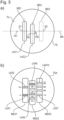
- the Figure 5A shows a schematic representation of a preferred embodiment of a carrier layer segment TS with at least two membrane segments MS1, MS2. A further, third membrane segment MS3 is preferably present.
- the membrane segments MS1, MS2 each have an elongated extension.
- the membrane segments MS1, MS2 each have a longitudinal axis LAC1, LAC2 along their elongated extent. Furthermore, the membrane segments MS1, MS2 each have a transverse axis Q1, Q2 perpendicular to the longitudinal axis LAC1, LAC2.
- the carrier layer segment TS has a circular base area FL.
- the membrane segments MS1, MS2 are positioned on the carrier layer segment TS in such a way that the elongated membrane segments MS1, MS2 are positioned in a special way on the carrier layer segment TS.
- the carrier membrane segments MS1, MS2 are positioned with their respective longitudinal axes LAC1, LAC2 perpendicular to a specific central axis MA of the circular base area FL of the carrier layer segment TS.
- the first carrier membrane segment MS1 is positioned with its transverse axis Q1 offset from the central axis MA by a first distance DI1.
- this distance DI1 is zero (0).
- the second carrier membrane segment MS2 is positioned with its transverse axis Q2 offset from the central axis MA by a second distance DI2. This second distance DI2 differs from the first distance DI1.
- This embodiment of a carrier segment TS with membrane segments MS1, MS2 within a microtiter plate is therefore particularly advantageous since, due to the spatial arrangement of the membrane segments MS1, MS2, there is a clear assignment of corresponding image areas MSX11, MSX12, see Figure 6C , the corresponding membrane segments MS1, MS2 can be made to specific membrane segment types.
- the first membrane segment MS1 Figure 5A be a membrane segment MSX1, on which a first line segment LAX1 of a blot line is present.
- a second line segment LAX2 may be present.
- the LAX1 line segment may be a serum control.
- the LAX2 line segment may be a conjugate control.
- the second membrane segment MS2 can be a membrane segment MSX2, which has four different bands or line segments of blot lines. These can be line segments LAX3 to LAX6.
- the line segment LAX3 can have a first type of capture molecule and the line segment LAX4 can have a second type of capture molecule.
- a microtiter plate proposed here having corresponding carrier membrane segments can therefore be incubated with a patient sample, a conjugate and a substrate. An image can then also be captured which represents the carrier layer segment and the carrier membrane segments.
- the Figure 6A shows an exemplary embodiment of a microtiter plate MTX with corresponding membrane segments and discolorations on the bands or line segments.
- the Figure 6B shows an exemplary image B, which represents a carrier layer segment with carrier membrane segments located thereon.
- the Figure 6C shows respective image sections of image B from the Figure 6B , which represent respective membrane segments MSX11, MSX12, MSX13.
- the Figure 7A shows basic steps of a digital image processing process.
- a step S1 the image which represents the carrier layer segment and the carrier membrane segments is captured.
- the first carrier membrane segment and the second carrier membrane segment are identified in the image, in particular by means of a provided data set DA.
- This data set indexes at least two types of carrier membrane segments as well as respective positions of the types of carrier membrane segments relative to a central axis of a circular surface of a carrier layer segment.
- the data set DA indexes distances of transverse axes of the membrane segments relative to a central axis of the circular surface of the carrier layer segment.
- respective binding measures are determined, which indicate a respective binding of antibodies or antigens to respective blot line segments.
- binding dimensions can be derived from gray values of corresponding bands or line segments or line sections of the membrane segments.
- a step S4 the respective binding dimensions are output.
- the Figure 7B shows a first particular embodiment of the in relation Figure 7A explained procedure.
- FIG. 7B An image is captured in a step S10.
- a step S11 a circular area of the carrier layer segment, as in Figure 5A shown, recognized using a segmentation step.
- respective membrane segment areas are recognized by means of segmentation.
- the transverse axes of the membrane segment surfaces are determined.
- the central axis of the circular carrier layer segment is determined, this central axis running parallel to the transverse axes of the membrane segment surfaces.
- a data set DA is provided, which can preferably be referred to as higher knowledge.
- This data set DA indexes a respective membrane segment type for respective distances of respective transverse axes relative to the central axis.
- the data set indexes a corresponding spatial sequence of line segments or corresponding bands with capture molecule types on the corresponding membrane segment. From this, the sequence of the bands or line segments with the corresponding capture molecule can be shown in a corresponding partial image of a membrane segment, as in Figure 6C represented, derived.
- a step S16 the band intensity or the line segments are analyzed by means of digital image processing of an output of corresponding binding measures, which indicate the respective binding of antibodies or antigens to respective blot line segments.
- Such a binding measure can be, for example, a medium gray area with a band or a line segment.
- a commitment measure can, for example, be a qualitative commitment measure, which indicates a positive or negative decision.
- the Figure 7C shows an alternative image processing method compared to that of Figure 7B .
- the image is recorded in step S20. Furthermore, the membrane segment areas are recognized by means of segmentation in a step S21. Furthermore, in a step S22, the transverse axes of the membrane segment surfaces are determined. In the case that the carrier segment TS, see exemplary embodiment from the Figure 5A , has three membrane segments MS1, MS2, MS3, the respective positions of the respective transverse axes can then be determined. Furthermore, the relational distances in the longitudinal direction or orthogonal to the transverse axis to the other transverse axes can be determined for each transverse axis. Thus, for a specific transverse axis, a minimum distance is determined compared to another, closest transverse axis.
- the transverse axis Q1 has a minimum distance DI1 of 0 (zero) compared to the transverse axis Q3.
- the transverse axis Q2 has a minimum distance DI2 relative to the transverse axis Q1 and the transverse axis Q3.
- the transverse axis Q2 and thus the membrane segment MS2 can thus be clearly identified compared to the membrane segments MS1 and MS3. It can then be incorporated as higher knowledge in the form of a data set DA that a specific membrane segment, here the membrane segment MS2, has a greatest minimum distance with its transverse axis to all other transverse axes.
- the respective membrane segment types or membrane segments MS1, MS2, MS3 or MSX1, MSX2, MSX3 can then be identified in order to also reliably identify their spatial orientation and thus the sequence of the corresponding line segments LAX1, LAX2, LAX3, LAX6, LAX7, LAX10 .
- a step S24 the band intensities are then analyzed via image processing and the respective binding measures for the respective bands are output.
- the data set indexes respective membrane segment types for respective spatial positions of respective transverse axes.
- the data set indexes for each membrane segment type and a corresponding spatial sequence of line segments or corresponding bands with capture molecule types on the corresponding membrane segment.
- the data record can also be in the form of several partial data records.
- an image B is captured, which represents the carrier layer segment TS and the carrier membrane segments MS1, MS2.
- a data set is provided which indexes respective membrane segment types for respective spatial positions of respective transverse axes.
- the first carrier membrane segment MS1 and the second carrier membrane segment MS2 are identified in the image B using the data set.
- partial images MSX11, MSX12 are provided, which represent the respective membrane segments MS1, MS2, and the respective membrane segment types are indexed to the respective partial images MSX11, MSX12.
- This indexing of the membrane segment types can be done by providing the partial images MSX11, MSX12 in a specific order. Alternatively, this indexing can be done by providing a respective partial image MSX11, MSX12 together with a respective partial data set, which indexes the respective membrane segment type for a respective partial image.
- respective binding measures are preferably determined, which indicate a respective binding of antibodies or antigens to respective blot line segments, and the respective binding measures are output.
- the membrane segments can preferably be referred to as blot strips or line blot strips Reference 1 (Raoult, D, and Dasch, GA, 1989, The line blot: an immunoassay for monoclonal and other antibodies. Its application to the serotyping of gram-negative bacteria. J. Immunol. Methods, 125 (1-2), 57-65 ; WO2013041540 ).
- the term “blot strip” or “line blot” or “membrane segment” in the sense of this application is viewed as a test strip, particularly preferably as a membrane-based strip, which is coated with at least two different substances for capturing antibodies or antigens, whereby the Substances are preferably polypeptides. These two substances are preferably applied as respective line segments spatially separated from one another on the membrane segment or the line blot or the test strip.
- Such a membrane segment or such a test strip or line blot preferably has one or more areas which are called a control band, such a control band being suitable for confirming that the membrane segment or line blot or test strip is long enough and under appropriate conditions a patient sample was contacted.
- the patient sample is preferably human blood, preferably human blood plasma or human blood serum, particularly preferably diluted human blood plasma or diluted human blood serum.
- Different line blots of two blot strips are described in the prior art, for example in Reference 2 ( van Oss, JC, and Regenmortel, MHV, Immunochemistry, 1994, Marcell Dekker, especially Chapter 35 ).
- a carrier membrane is preferably a nitrocellulose membrane, a nylon membrane or a PVDF membrane.
- the carrier membrane is therefore suitable for adsorbing a solution of capture molecule and buffer.
- the membrane is coated with a capture molecule by applying such a solution to the membrane.
- a carrier layer is preferably a mechanically strong plastic layer or a mechanically flexible plastic film.
- the plastic can in particular be PET (polyethylene terephthalate), in particular antistatic PET.
- a blocking buffer is a buffer that enables non-specific binding of the detection antibody or the detection antigen to the surface of the membrane prevented.
- a buffer contains either proteins or other components to block binding sites so that non-specific binding is prevented.
- a double-sided adhesive film can be a film which is coated on both sides with an adhesion promoter described above.
- aspects have been described in connection with a device, it is understood that these aspects also represent a description of the corresponding method, so that a block or a component of a device is also to be understood as a corresponding method step or as a feature of a method step. Analogously, aspects that were described in connection with or as a method step also represent a description of a corresponding feature of a corresponding device.
- the line blot strips were processed manually in a blot tray according to instructions DN_2131G_A_DE_C11 for the product Anti-Borrelia-EUROLINE-RN-AT (IgG).
- the antigens and antibodies in the microtiter plate were processed according to the same instructions, adjusting the volumes of the reagents. This adjustment took into account the volume difference between the blot tray and the well of the microtiter plate.
- the image capture and evaluation of the line blot strips was initially carried out using the products EUROBlotScanner and EUROLineScan.
- the well images were captured in a second approach using a newly developed image capture system; the well images were also evaluated using the EUROLineScan product.
- the Figure 8 shows a table with results. For different antigens and antibodies and different numbers of patient samples, there is an intensity value for the corresponding band for a line blot strip (EL) and for a well of a microtiter plate (MTP).
- the intensity values of the two approaches are comparable or highly correlated with each other, as will be seen later with reference to Figure 9 still explained.
- the respective positive/negative evaluations for the respective line blot strip (EL) and microtiter plate (MTP) approaches using respective, individual threshold values for the respective approaches can be found in the last two columns. Here it can be seen that all the respective positive/negative evaluations agree.
- the serum control and the conjugate control each used antibodies as capture molecules. These antibodies of the respective controls are each anti-human antibodies.
- the antigen called p39 is also known as BmpA; a corresponding Uniprot number is P0C223.
- the antigen, designated DbpA has a corresponding Uniprot number O50917.
- the antigen called p41 is also known as flagellin; a corresponding Uniprot number is C3VMP5.
- the antigen designated p100 has a corresponding Uniprot number Q45013.
- the antigen with the name VIsE Ba is also known as VIsE Borrelia afzelii, a corresponding Uniprot number is Q5DVM0.
- the antigen with the name VIsE Bb is also known under the name VIsE Borrelia burgdorferi, a corresponding Uniprot number is O06878.
- the antigen with the name VIsE Bg is also known as VIsE Borrelia garinii, a corresponding Uniprot number is Q5DVM1.
- the antigen called OspC Mix is also known as OspC; a corresponding Uniprot number is Q07337.
- Figure 9 shows a correlation of the intensity values for common line blot strips (EUROLINE) on the x-axis and wells of microtiter plates (EUROMicroblot) on the y-axis across all Antigens as well as antibodies and all patient samples.
Landscapes
- Health & Medical Sciences (AREA)
- Immunology (AREA)
- Life Sciences & Earth Sciences (AREA)
- Engineering & Computer Science (AREA)
- Molecular Biology (AREA)
- Biomedical Technology (AREA)
- Chemical & Material Sciences (AREA)
- Hematology (AREA)
- Urology & Nephrology (AREA)
- Biotechnology (AREA)
- Microbiology (AREA)
- Cell Biology (AREA)
- Food Science & Technology (AREA)
- Medicinal Chemistry (AREA)
- Physics & Mathematics (AREA)
- Analytical Chemistry (AREA)
- Biochemistry (AREA)
- General Health & Medical Sciences (AREA)
- General Physics & Mathematics (AREA)
- Pathology (AREA)
- Apparatus Associated With Microorganisms And Enzymes (AREA)
Priority Applications (3)
| Application Number | Priority Date | Filing Date | Title |
|---|---|---|---|
| PT221600182T PT4239336T (pt) | 2022-03-03 | 2022-03-03 | Método para a produção de uma placa de microtitulação com revestimentos de moléculas de captura e placa de microtitulação |
| PL22160018.2T PL4239336T3 (pl) | 2022-03-03 | 2022-03-03 | Sposób wytwarzania płytki mikromiareczkowanej z powłokami wychwytujących cząsteczek i płytka mikromiareczkowana |
| EP22160018.2A EP4239336B1 (de) | 2022-03-03 | 2022-03-03 | Verfahren zum herstellen einer mikrotiterplatte mit fängermolekülbeschichtungen und mikrotiterplatte |
Applications Claiming Priority (1)
| Application Number | Priority Date | Filing Date | Title |
|---|---|---|---|
| EP22160018.2A EP4239336B1 (de) | 2022-03-03 | 2022-03-03 | Verfahren zum herstellen einer mikrotiterplatte mit fängermolekülbeschichtungen und mikrotiterplatte |
Publications (2)
| Publication Number | Publication Date |
|---|---|
| EP4239336A1 EP4239336A1 (de) | 2023-09-06 |
| EP4239336B1 true EP4239336B1 (de) | 2024-01-10 |
Family
ID=80628835
Family Applications (1)
| Application Number | Title | Priority Date | Filing Date |
|---|---|---|---|
| EP22160018.2A Active EP4239336B1 (de) | 2022-03-03 | 2022-03-03 | Verfahren zum herstellen einer mikrotiterplatte mit fängermolekülbeschichtungen und mikrotiterplatte |
Country Status (3)
| Country | Link |
|---|---|
| EP (1) | EP4239336B1 (pl) |
| PL (1) | PL4239336T3 (pl) |
| PT (1) | PT4239336T (pl) |
Family Cites Families (6)
| Publication number | Priority date | Publication date | Assignee | Title |
|---|---|---|---|---|
| US20080200342A1 (en) * | 2007-02-15 | 2008-08-21 | Rao Rupa S | Device, Array, And Methods For Disease Detection And Analysis |
| EP2138422A1 (de) | 2008-06-27 | 2009-12-30 | Teich Aktiengesellschaft | Platine zum Verschliessen eines Bechers |
| DE102009019476A1 (de) | 2009-05-04 | 2010-11-11 | Biametrics Marken Und Rechte Gmbh | Wiedererkennbarer Träger für optische Meßverfahren |
| DE202011106093U1 (de) | 2011-09-24 | 2011-10-19 | Euroimmun Medizinische Labordiagnostika Ag | Kalibrationsstreifen für einen Immunoblot |
| US9063134B2 (en) * | 2012-07-09 | 2015-06-23 | Yantai Zestern Biotechnique Co. LTD | Multi-unit plate for immunoblot analysis |
| DE102013008468A1 (de) * | 2013-05-21 | 2014-11-27 | Euroimmun Medizinische Labordiagnostika Ag | Verfahren zur automatisierten Auswertung von inkubierten lmmunoblotstreifen |
-
2022
- 2022-03-03 PT PT221600182T patent/PT4239336T/pt unknown
- 2022-03-03 EP EP22160018.2A patent/EP4239336B1/de active Active
- 2022-03-03 PL PL22160018.2T patent/PL4239336T3/pl unknown
Non-Patent Citations (1)
| Title |
|---|
| "Bio-Dot SF Microfiltration Apparatus - Instruction Manual - Catalog Number 170-6542, 170-6543", 2 April 2013, BIORAD, pages: 1 - 24 * |
Also Published As
| Publication number | Publication date |
|---|---|
| PL4239336T3 (pl) | 2024-06-24 |
| PT4239336T (pt) | 2024-03-14 |
| EP4239336A1 (de) | 2023-09-06 |
Similar Documents
| Publication | Publication Date | Title |
|---|---|---|
| EP2758783B1 (de) | Ein immunoblot verfahren | |
| EP0810428B1 (de) | Automatisierte Vorrichtung und Verfahren zum Messen und Bestimmen von Molekülen oder Teilen davon | |
| DE3322373A1 (de) | Partikel sowie verfahren zum nachweis von antigenen und/oder antikoerpern unter verwendung der partikel | |
| EP1716418A2 (de) | Vorrichtung und verfahren zur optischen auswertung von teststreifen | |
| DE10014685A1 (de) | Verfahren zur Identifizierung von zellspezifischen Zielstrukturen | |
| DE10020704B4 (de) | Biochip zur Archivierung und labormedizinischen Analyse von biologischem Probenmaterial, Verfahren zu dessen Herstellung sowie dessen Verwendung in diagnostischen Verfahren | |
| DE69531575T2 (de) | Lesekopf mit veränderbarer Auflösung | |
| DE10392707T5 (de) | Verfahren zur Verwendung von Datenbinning bei der Analyse von Chromatographie-/Spektrometriedaten | |
| DE60215302T2 (de) | Einrichtungen und verfahren für bildobjekte | |
| EP4239336B1 (de) | Verfahren zum herstellen einer mikrotiterplatte mit fängermolekülbeschichtungen und mikrotiterplatte | |
| EP1430309A2 (de) | Teststreifen für den nachweis von prionproteinen | |
| EP3591403B1 (de) | Verfahren zum automatisierten detektieren von antikörpern in einer flüssigen biologischen probe unter verwendung eines antigen-chips | |
| DE102011117320A1 (de) | Vorrichtung und Verfahren zum Nachweis von in biologischen oder chemischen Proben vorliegenden Substanzen | |
| DE102011117311A1 (de) | Vorrichtung und Verfahren zum Nachweis von in biologischen oder chemischen Proben vorliegenden Substanzen | |
| WO2013060482A1 (de) | Vorrichtung und verfahren zum nachweis von in biologischen oder chemischen proben vorliegenden substanzen | |
| DE60317497T2 (de) | Verfahren, system und kit zum nachweis eines analyten in einer probe | |
| EP0374686B1 (de) | Verfahren zur Verbesserung von Richtigkeit und Reproduzierbarkeit der Messdaten immunometrischer Tests | |
| EP2771697B1 (de) | Vorrichtung und verfahren zum nachweis von in biologischen oder chemischen proben vorliegenden substanzen | |
| EP2771672B1 (de) | Vorrichtung und verfahren zum nachweis von in biologischen oder chemischen proben vorliegenden substanzen | |
| EP1713589B1 (de) | Testelement und verfahren zum testen von blut | |
| EP2059906A2 (de) | Verfahren zur quantitativen bestimmung der kolokalisation von molekülmarkern in gewebeschnitten | |
| DE102007000627A1 (de) | Gekoppelte Darstellung von Flüssigchromatographie-Daten und Massenspektrometrie-Daten, insbesondere von Fragmentdaten | |
| DE19645569C1 (de) | Vorrichtung zum quantifizierenden und differenzierenden Nachweis verschiedener Biomoleküle in einem einzigen Testansatz | |
| DE19628821A1 (de) | Verfahren zur Untersuchung der Nierenfunktion | |
| EP2589950A1 (de) | Probenanalysevorrichtung zum Bestimmen von Proben in einer Probenmatrix und Verfahren zum Bestimmen von Proben in einer oder mehreren Probenmatrizen |
Legal Events
| Date | Code | Title | Description |
|---|---|---|---|
| PUAI | Public reference made under article 153(3) epc to a published international application that has entered the european phase |
Free format text: ORIGINAL CODE: 0009012 |
|
| STAA | Information on the status of an ep patent application or granted ep patent |
Free format text: STATUS: REQUEST FOR EXAMINATION WAS MADE |
|
| 17P | Request for examination filed |
Effective date: 20230228 |
|
| AK | Designated contracting states |
Kind code of ref document: A1 Designated state(s): AL AT BE BG CH CY CZ DE DK EE ES FI FR GB GR HR HU IE IS IT LI LT LU LV MC MK MT NL NO PL PT RO RS SE SI SK SM TR |
|
| GRAP | Despatch of communication of intention to grant a patent |
Free format text: ORIGINAL CODE: EPIDOSNIGR1 |
|
| STAA | Information on the status of an ep patent application or granted ep patent |
Free format text: STATUS: GRANT OF PATENT IS INTENDED |
|
| INTG | Intention to grant announced |
Effective date: 20230920 |
|
| GRAS | Grant fee paid |
Free format text: ORIGINAL CODE: EPIDOSNIGR3 |
|
| GRAA | (expected) grant |
Free format text: ORIGINAL CODE: 0009210 |
|
| STAA | Information on the status of an ep patent application or granted ep patent |
Free format text: STATUS: THE PATENT HAS BEEN GRANTED |
|
| AK | Designated contracting states |
Kind code of ref document: B1 Designated state(s): AL AT BE BG CH CY CZ DE DK EE ES FI FR GB GR HR HU IE IS IT LI LT LU LV MC MK MT NL NO PL PT RO RS SE SI SK SM TR |
|
| REG | Reference to a national code |
Ref country code: GB Ref legal event code: FG4D Free format text: NOT ENGLISH |
|
| REG | Reference to a national code |
Ref country code: CH Ref legal event code: EP |
|
| REG | Reference to a national code |
Ref country code: DE Ref legal event code: R096 Ref document number: 502022000384 Country of ref document: DE |
|
| REG | Reference to a national code |
Ref country code: IE Ref legal event code: FG4D Free format text: LANGUAGE OF EP DOCUMENT: GERMAN |
|
| REG | Reference to a national code |
Ref country code: PT Ref legal event code: SC4A Ref document number: 4239336 Country of ref document: PT Date of ref document: 20240314 Kind code of ref document: T Free format text: AVAILABILITY OF NATIONAL TRANSLATION Effective date: 20240311 |
|
| P01 | Opt-out of the competence of the unified patent court (upc) registered |
Effective date: 20240229 |
|
| REG | Reference to a national code |
Ref country code: LT Ref legal event code: MG9D |
|
| REG | Reference to a national code |
Ref country code: NL Ref legal event code: MP Effective date: 20240110 |
|
| PG25 | Lapsed in a contracting state [announced via postgrant information from national office to epo] |
Ref country code: NL Free format text: LAPSE BECAUSE OF FAILURE TO SUBMIT A TRANSLATION OF THE DESCRIPTION OR TO PAY THE FEE WITHIN THE PRESCRIBED TIME-LIMIT Effective date: 20240110 |
|
| PG25 | Lapsed in a contracting state [announced via postgrant information from national office to epo] |
Ref country code: NL Free format text: LAPSE BECAUSE OF FAILURE TO SUBMIT A TRANSLATION OF THE DESCRIPTION OR TO PAY THE FEE WITHIN THE PRESCRIBED TIME-LIMIT Effective date: 20240110 |
|
| PG25 | Lapsed in a contracting state [announced via postgrant information from national office to epo] |
Ref country code: IS Free format text: LAPSE BECAUSE OF FAILURE TO SUBMIT A TRANSLATION OF THE DESCRIPTION OR TO PAY THE FEE WITHIN THE PRESCRIBED TIME-LIMIT Effective date: 20240510 |
|
| PG25 | Lapsed in a contracting state [announced via postgrant information from national office to epo] |
Ref country code: LT Free format text: LAPSE BECAUSE OF FAILURE TO SUBMIT A TRANSLATION OF THE DESCRIPTION OR TO PAY THE FEE WITHIN THE PRESCRIBED TIME-LIMIT Effective date: 20240110 |
|
| PG25 | Lapsed in a contracting state [announced via postgrant information from national office to epo] |
Ref country code: GR Free format text: LAPSE BECAUSE OF FAILURE TO SUBMIT A TRANSLATION OF THE DESCRIPTION OR TO PAY THE FEE WITHIN THE PRESCRIBED TIME-LIMIT Effective date: 20240411 |
|
| PG25 | Lapsed in a contracting state [announced via postgrant information from national office to epo] |
Ref country code: RS Free format text: LAPSE BECAUSE OF FAILURE TO SUBMIT A TRANSLATION OF THE DESCRIPTION OR TO PAY THE FEE WITHIN THE PRESCRIBED TIME-LIMIT Effective date: 20240410 Ref country code: HR Free format text: LAPSE BECAUSE OF FAILURE TO SUBMIT A TRANSLATION OF THE DESCRIPTION OR TO PAY THE FEE WITHIN THE PRESCRIBED TIME-LIMIT Effective date: 20240110 |
|
| PG25 | Lapsed in a contracting state [announced via postgrant information from national office to epo] |
Ref country code: ES Free format text: LAPSE BECAUSE OF FAILURE TO SUBMIT A TRANSLATION OF THE DESCRIPTION OR TO PAY THE FEE WITHIN THE PRESCRIBED TIME-LIMIT Effective date: 20240110 |
|
| PG25 | Lapsed in a contracting state [announced via postgrant information from national office to epo] |
Ref country code: RS Free format text: LAPSE BECAUSE OF FAILURE TO SUBMIT A TRANSLATION OF THE DESCRIPTION OR TO PAY THE FEE WITHIN THE PRESCRIBED TIME-LIMIT Effective date: 20240410 Ref country code: NO Free format text: LAPSE BECAUSE OF FAILURE TO SUBMIT A TRANSLATION OF THE DESCRIPTION OR TO PAY THE FEE WITHIN THE PRESCRIBED TIME-LIMIT Effective date: 20240410 Ref country code: LT Free format text: LAPSE BECAUSE OF FAILURE TO SUBMIT A TRANSLATION OF THE DESCRIPTION OR TO PAY THE FEE WITHIN THE PRESCRIBED TIME-LIMIT Effective date: 20240110 Ref country code: IS Free format text: LAPSE BECAUSE OF FAILURE TO SUBMIT A TRANSLATION OF THE DESCRIPTION OR TO PAY THE FEE WITHIN THE PRESCRIBED TIME-LIMIT Effective date: 20240510 Ref country code: HR Free format text: LAPSE BECAUSE OF FAILURE TO SUBMIT A TRANSLATION OF THE DESCRIPTION OR TO PAY THE FEE WITHIN THE PRESCRIBED TIME-LIMIT Effective date: 20240110 Ref country code: GR Free format text: LAPSE BECAUSE OF FAILURE TO SUBMIT A TRANSLATION OF THE DESCRIPTION OR TO PAY THE FEE WITHIN THE PRESCRIBED TIME-LIMIT Effective date: 20240411 Ref country code: ES Free format text: LAPSE BECAUSE OF FAILURE TO SUBMIT A TRANSLATION OF THE DESCRIPTION OR TO PAY THE FEE WITHIN THE PRESCRIBED TIME-LIMIT Effective date: 20240110 Ref country code: BG Free format text: LAPSE BECAUSE OF FAILURE TO SUBMIT A TRANSLATION OF THE DESCRIPTION OR TO PAY THE FEE WITHIN THE PRESCRIBED TIME-LIMIT Effective date: 20240110 |
|
| PG25 | Lapsed in a contracting state [announced via postgrant information from national office to epo] |
Ref country code: SE Free format text: LAPSE BECAUSE OF FAILURE TO SUBMIT A TRANSLATION OF THE DESCRIPTION OR TO PAY THE FEE WITHIN THE PRESCRIBED TIME-LIMIT Effective date: 20240110 Ref country code: LV Free format text: LAPSE BECAUSE OF FAILURE TO SUBMIT A TRANSLATION OF THE DESCRIPTION OR TO PAY THE FEE WITHIN THE PRESCRIBED TIME-LIMIT Effective date: 20240110 |
|
| PG25 | Lapsed in a contracting state [announced via postgrant information from national office to epo] |
Ref country code: DK Free format text: LAPSE BECAUSE OF FAILURE TO SUBMIT A TRANSLATION OF THE DESCRIPTION OR TO PAY THE FEE WITHIN THE PRESCRIBED TIME-LIMIT Effective date: 20240110 |
|
| REG | Reference to a national code |
Ref country code: DE Ref legal event code: R097 Ref document number: 502022000384 Country of ref document: DE |
|
| PG25 | Lapsed in a contracting state [announced via postgrant information from national office to epo] |
Ref country code: SM Free format text: LAPSE BECAUSE OF FAILURE TO SUBMIT A TRANSLATION OF THE DESCRIPTION OR TO PAY THE FEE WITHIN THE PRESCRIBED TIME-LIMIT Effective date: 20240110 |
|
| PG25 | Lapsed in a contracting state [announced via postgrant information from national office to epo] |
Ref country code: EE Free format text: LAPSE BECAUSE OF FAILURE TO SUBMIT A TRANSLATION OF THE DESCRIPTION OR TO PAY THE FEE WITHIN THE PRESCRIBED TIME-LIMIT Effective date: 20240110 |
|
| PG25 | Lapsed in a contracting state [announced via postgrant information from national office to epo] |
Ref country code: SK Free format text: LAPSE BECAUSE OF FAILURE TO SUBMIT A TRANSLATION OF THE DESCRIPTION OR TO PAY THE FEE WITHIN THE PRESCRIBED TIME-LIMIT Effective date: 20240110 |
|
| PG25 | Lapsed in a contracting state [announced via postgrant information from national office to epo] |
Ref country code: SM Free format text: LAPSE BECAUSE OF FAILURE TO SUBMIT A TRANSLATION OF THE DESCRIPTION OR TO PAY THE FEE WITHIN THE PRESCRIBED TIME-LIMIT Effective date: 20240110 Ref country code: SK Free format text: LAPSE BECAUSE OF FAILURE TO SUBMIT A TRANSLATION OF THE DESCRIPTION OR TO PAY THE FEE WITHIN THE PRESCRIBED TIME-LIMIT Effective date: 20240110 Ref country code: RO Free format text: LAPSE BECAUSE OF FAILURE TO SUBMIT A TRANSLATION OF THE DESCRIPTION OR TO PAY THE FEE WITHIN THE PRESCRIBED TIME-LIMIT Effective date: 20240110 Ref country code: EE Free format text: LAPSE BECAUSE OF FAILURE TO SUBMIT A TRANSLATION OF THE DESCRIPTION OR TO PAY THE FEE WITHIN THE PRESCRIBED TIME-LIMIT Effective date: 20240110 Ref country code: DK Free format text: LAPSE BECAUSE OF FAILURE TO SUBMIT A TRANSLATION OF THE DESCRIPTION OR TO PAY THE FEE WITHIN THE PRESCRIBED TIME-LIMIT Effective date: 20240110 |
|
| PLBE | No opposition filed within time limit |
Free format text: ORIGINAL CODE: 0009261 |
|
| STAA | Information on the status of an ep patent application or granted ep patent |
Free format text: STATUS: NO OPPOSITION FILED WITHIN TIME LIMIT |
|
| PG25 | Lapsed in a contracting state [announced via postgrant information from national office to epo] |
Ref country code: LU Free format text: LAPSE BECAUSE OF NON-PAYMENT OF DUE FEES Effective date: 20240303 |
|
| PG25 | Lapsed in a contracting state [announced via postgrant information from national office to epo] |
Ref country code: MC Free format text: LAPSE BECAUSE OF FAILURE TO SUBMIT A TRANSLATION OF THE DESCRIPTION OR TO PAY THE FEE WITHIN THE PRESCRIBED TIME-LIMIT Effective date: 20240110 |
|
| PG25 | Lapsed in a contracting state [announced via postgrant information from national office to epo] |
Ref country code: MC Free format text: LAPSE BECAUSE OF FAILURE TO SUBMIT A TRANSLATION OF THE DESCRIPTION OR TO PAY THE FEE WITHIN THE PRESCRIBED TIME-LIMIT Effective date: 20240110 Ref country code: LU Free format text: LAPSE BECAUSE OF NON-PAYMENT OF DUE FEES Effective date: 20240303 |
|
| PG25 | Lapsed in a contracting state [announced via postgrant information from national office to epo] |
Ref country code: IT Free format text: LAPSE BECAUSE OF FAILURE TO SUBMIT A TRANSLATION OF THE DESCRIPTION OR TO PAY THE FEE WITHIN THE PRESCRIBED TIME-LIMIT Effective date: 20240110 |
|
| 26N | No opposition filed |
Effective date: 20241011 |
|
| PG25 | Lapsed in a contracting state [announced via postgrant information from national office to epo] |
Ref country code: IT Free format text: LAPSE BECAUSE OF FAILURE TO SUBMIT A TRANSLATION OF THE DESCRIPTION OR TO PAY THE FEE WITHIN THE PRESCRIBED TIME-LIMIT Effective date: 20240110 |
|
| PG25 | Lapsed in a contracting state [announced via postgrant information from national office to epo] |
Ref country code: IE Free format text: LAPSE BECAUSE OF NON-PAYMENT OF DUE FEES Effective date: 20240303 |
|
| PG25 | Lapsed in a contracting state [announced via postgrant information from national office to epo] |
Ref country code: IE Free format text: LAPSE BECAUSE OF NON-PAYMENT OF DUE FEES Effective date: 20240303 |
|
| PG25 | Lapsed in a contracting state [announced via postgrant information from national office to epo] |
Ref country code: SI Free format text: LAPSE BECAUSE OF FAILURE TO SUBMIT A TRANSLATION OF THE DESCRIPTION OR TO PAY THE FEE WITHIN THE PRESCRIBED TIME-LIMIT Effective date: 20240110 |
|
| PG25 | Lapsed in a contracting state [announced via postgrant information from national office to epo] |
Ref country code: CY Free format text: LAPSE BECAUSE OF FAILURE TO SUBMIT A TRANSLATION OF THE DESCRIPTION OR TO PAY THE FEE WITHIN THE PRESCRIBED TIME-LIMIT; INVALID AB INITIO Effective date: 20220303 |
|
| PG25 | Lapsed in a contracting state [announced via postgrant information from national office to epo] |
Ref country code: FI Free format text: LAPSE BECAUSE OF FAILURE TO SUBMIT A TRANSLATION OF THE DESCRIPTION OR TO PAY THE FEE WITHIN THE PRESCRIBED TIME-LIMIT Effective date: 20240110 |
|
| REG | Reference to a national code |
Ref country code: CH Ref legal event code: H13 Free format text: ST27 STATUS EVENT CODE: U-0-0-H10-H13 (AS PROVIDED BY THE NATIONAL OFFICE) Effective date: 20251024 |
|
| PG25 | Lapsed in a contracting state [announced via postgrant information from national office to epo] |
Ref country code: TR Free format text: LAPSE BECAUSE OF FAILURE TO SUBMIT A TRANSLATION OF THE DESCRIPTION OR TO PAY THE FEE WITHIN THE PRESCRIBED TIME-LIMIT Effective date: 20240110 |
|
| PG25 | Lapsed in a contracting state [announced via postgrant information from national office to epo] |
Ref country code: CH Free format text: LAPSE BECAUSE OF NON-PAYMENT OF DUE FEES Effective date: 20250331 |
|
| PGFP | Annual fee paid to national office [announced via postgrant information from national office to epo] |
Ref country code: DE Payment date: 20260320 Year of fee payment: 5 |
|
| PGFP | Annual fee paid to national office [announced via postgrant information from national office to epo] |
Ref country code: AT Payment date: 20260301 Year of fee payment: 5 |
|
| PGFP | Annual fee paid to national office [announced via postgrant information from national office to epo] |
Ref country code: BE Payment date: 20260323 Year of fee payment: 5 |
|
| PGFP | Annual fee paid to national office [announced via postgrant information from national office to epo] |
Ref country code: FR Payment date: 20260325 Year of fee payment: 5 |
|
| PGFP | Annual fee paid to national office [announced via postgrant information from national office to epo] |
Ref country code: PT Payment date: 20260219 Year of fee payment: 5 Ref country code: CZ Payment date: 20260218 Year of fee payment: 5 |
|
| PGFP | Annual fee paid to national office [announced via postgrant information from national office to epo] |
Ref country code: PL Payment date: 20260218 Year of fee payment: 5 |