EP4239130B1 - Schlitzwandfräse und verfahren zum erstellen eines frässchlitzes im boden - Google Patents
Schlitzwandfräse und verfahren zum erstellen eines frässchlitzes im boden Download PDFInfo
- Publication number
- EP4239130B1 EP4239130B1 EP22159510.1A EP22159510A EP4239130B1 EP 4239130 B1 EP4239130 B1 EP 4239130B1 EP 22159510 A EP22159510 A EP 22159510A EP 4239130 B1 EP4239130 B1 EP 4239130B1
- Authority
- EP
- European Patent Office
- Prior art keywords
- plate
- housing
- trench cutter
- clearing
- cutting
- Prior art date
- Legal status (The legal status is an assumption and is not a legal conclusion. Google has not performed a legal analysis and makes no representation as to the accuracy of the status listed.)
- Active
Links
Images

Classifications
-
- E—FIXED CONSTRUCTIONS
- E02—HYDRAULIC ENGINEERING; FOUNDATIONS; SOIL SHIFTING
- E02F—DREDGING; SOIL-SHIFTING
- E02F3/00—Dredgers; Soil-shifting machines
- E02F3/04—Dredgers; Soil-shifting machines mechanically-driven
- E02F3/18—Dredgers; Soil-shifting machines mechanically-driven with digging wheels turning round an axis, e.g. bucket-type wheels
- E02F3/20—Dredgers; Soil-shifting machines mechanically-driven with digging wheels turning round an axis, e.g. bucket-type wheels with tools that only loosen the material, i.e. mill-type wheels
- E02F3/205—Dredgers; Soil-shifting machines mechanically-driven with digging wheels turning round an axis, e.g. bucket-type wheels with tools that only loosen the material, i.e. mill-type wheels with a pair of digging wheels, e.g. slotting machines
-
- E—FIXED CONSTRUCTIONS
- E02—HYDRAULIC ENGINEERING; FOUNDATIONS; SOIL SHIFTING
- E02D—FOUNDATIONS; EXCAVATIONS; EMBANKMENTS; UNDERGROUND OR UNDERWATER STRUCTURES
- E02D17/00—Excavations; Bordering of excavations; Making embankments
- E02D17/13—Foundation slots or slits; Implements for making these slots or slits
-
- E—FIXED CONSTRUCTIONS
- E02—HYDRAULIC ENGINEERING; FOUNDATIONS; SOIL SHIFTING
- E02F—DREDGING; SOIL-SHIFTING
- E02F3/00—Dredgers; Soil-shifting machines
- E02F3/04—Dredgers; Soil-shifting machines mechanically-driven
- E02F3/18—Dredgers; Soil-shifting machines mechanically-driven with digging wheels turning round an axis, e.g. bucket-type wheels
- E02F3/22—Component parts
- E02F3/24—Digging wheels; Digging elements of wheels; Drives for wheels
- E02F3/246—Digging wheels; Digging elements of wheels; Drives for wheels drives
-
- E—FIXED CONSTRUCTIONS
- E02—HYDRAULIC ENGINEERING; FOUNDATIONS; SOIL SHIFTING
- E02F—DREDGING; SOIL-SHIFTING
- E02F3/00—Dredgers; Soil-shifting machines
- E02F3/04—Dredgers; Soil-shifting machines mechanically-driven
- E02F3/18—Dredgers; Soil-shifting machines mechanically-driven with digging wheels turning round an axis, e.g. bucket-type wheels
- E02F3/22—Component parts
- E02F3/24—Digging wheels; Digging elements of wheels; Drives for wheels
- E02F3/248—Cleaning the wheels or emptying the digging elements mounted on the wheels, e.g. in combination with spoil removing equipment
-
- E—FIXED CONSTRUCTIONS
- E02—HYDRAULIC ENGINEERING; FOUNDATIONS; SOIL SHIFTING
- E02D—FOUNDATIONS; EXCAVATIONS; EMBANKMENTS; UNDERGROUND OR UNDERWATER STRUCTURES
- E02D2250/00—Production methods
- E02D2250/003—Injection of material
-
- E—FIXED CONSTRUCTIONS
- E02—HYDRAULIC ENGINEERING; FOUNDATIONS; SOIL SHIFTING
- E02D—FOUNDATIONS; EXCAVATIONS; EMBANKMENTS; UNDERGROUND OR UNDERWATER STRUCTURES
- E02D2300/00—Materials
- E02D2300/0004—Synthetics
- E02D2300/0018—Cement used as binder
- E02D2300/0023—Slurry
Definitions
- the invention relates to a trench wall cutter with a box-shaped housing, on the top of which a lifting device can be attached, at least one cutting wheel which is arranged on an underside of the housing and can be driven in rotation to remove soil material, wherein cutting teeth are arranged along the outer circumference of the cutting wheel in at least one circumferential row, to which at least one axial free space adjoins, and at least one clearing plate which is arranged relatively fixed to the housing and engages in the at least one circumferential free space on the cutting wheel to clear soil material, according to the preamble of claim 1.
- the invention further relates to a method for creating a milling slot in the ground according to the preamble of claim 14.
- a typical trench cutter with a cutter frame, which carries cutter wheels on the side below its base, whose tooth spaces can be cleaned using clearing plates, is known from the EP 3 543 408 known.
- a generic trench cutter for example, is based on the EP 1452645 A1 or from the EP 3 296 468 Rows of milling teeth are arranged along the circumference of the milling wheels, which are arranged in pairs. Between the rows of milling teeth there are axial spaces into which so-called clearing plates engage.
- the clearing plates are arranged on the underside of the box-shaped housing and serve to strip off any cohesive soil material adhering to the milling teeth, which can impair the milling performance, and thus keep the milling teeth free of cohesive soil material.
- the box-shaped housing with the drive unit of the generic diaphragm wall cutter is designed to be smaller in its outer circumference than the milling slot created. This creates a free space on the housing through which the milled soil material, which is mixed with the supplied hardening suspension to form the soil mortar by the milling wheels, has the opportunity to flow past the housing into an upper area of the milling slot.
- the cutter wheels When the trench wall cutter is in operation, the cutter wheels are driven in opposite directions, so that the two pairs of cutter wheels each rotate inwards and thus convey soil material into a central area below the cutter housing.
- the setting suspension can also be fed into this area in order to achieve a good mixing effect for forming the soil mortar.
- the invention is based on the object of specifying a trench wall cutter and a method for creating a milling slot, with which a particularly efficient operation when creating a milling slot is possible.
- a basic idea of the invention is not to arrange the clearing plates directly on the underside of the box-shaped housing, but rather at a distance from the box-shaped housing on plate holders.
- the plate holders are arranged and designed in such a way that the at least one clearing plate is arranged at a distance from the housing through which a passage is formed for the milled soil material. Milled soil material can be guided past the clearing plates through this passage, possibly with the suspension supplied, particularly when the milling wheels are driven inwards, and can thus flow upwards in a simplified manner.
- the hard rock material therefore does not have to be forced through the meshing arrangement between the milling teeth and the clearing plates.
- the actual clearing effect of the clearing plates is maintained when soil material adheres.
- the passage can have a size of a few centimeters up to approx. 40% of a milling wheel diameter in the horizontal longitudinal direction and a size up to the wheel width of a milling wheel in the horizontal width direction.
- a preferred embodiment of the invention consists in that at least two circumferential rows of milling teeth are arranged on the at least one milling wheel, which are axially spaced from one another by a circumferential clearance into which a clearing plate engages.
- more than two circumferential rows, in particular four or five circumferential rows, each with a corresponding axial distance from the adjacent row of teeth, can be arranged on the milling wheel.
- the existing clearances which generally have an axial width of 2 to 10 cm
- the clearing plates which are fixed relative to the housing, are engaged in the circumferential clearances by milling teeth driven by the milling wheel.
- the clearing plates can slightly contact the milling teeth and tooth holders moving past, i.e. scratch them, or be spaced apart from them at a small axial distance, for example a few millimeters.
- the at least one cutting wheel is mounted on a plate-shaped bearing plate on the underside of the housing and the at least one clearing plate is attached to the bearing plate with the plate holder.
- a drive device for driving the cutting wheels can be provided in the bearing plate.
- the plate holder can be a simple support arm to which the clearing plates are attached.
- the support arm can be arranged transversely to the center plane of the bearing plate.
- an L-shaped or T-shaped plate holder can also be attached to a side edge of the bearing plate or to the housing.
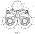
- each milling wheel of a milling wheel pair is arranged on a common central bearing plate on one side.
- the plate holders are arranged on the respective outside so that the clearing plates can engage in the circumferential spaces between the milling teeth at an angle from the outside to the inside.
- each pair of milling wheels is mounted on one side of the bearing plate and that each milling wheel is assigned at least one clearing plate, which is attached to the bearing plate via a plate holder.
- each clearing plate can also be provided on each plate holder, corresponding to the number of free spaces or gaps between the circumferential rows of the milling teeth.
- each cutting wheel is assigned a passage which is delimited by the housing, the bearing plate and the associated at least one clearing plate with the plate holder.
- This arrangement makes it possible, in particular, for harder rock material to avoid being forced through between the milling teeth with the tooth holders and the clearing plates by allowing the rock material in question to be drained upwards through the passage.
- a feed device for feeding a liquid, in particular a hardenable suspension, such as a cement suspension can be pumped from above ground to the diaphragm wall cutter in the cutter slot using a corresponding pumping device.
- the feed device is particularly expedient for the feed device to be arranged between two pairs of milling wheels and/or in at least one of the plate holders.
- the feed device can be arranged in a basically known manner between the two pairs of milling wheels in a central area on the underside of the box-shaped housing.
- the feed device can also be arranged on the at least one plate holder.
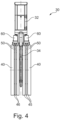
- the plate holder is at least partially hollow with a feed channel.
- the feed channel ends in one or more outlet nozzles for the liquid to flow out in the area of the clearing plates. This can improve the mixing effect and at the same time also cause additional free flow of cohesive material on the milling teeth.
- the arrangement of the clearing plates according to the invention via plate holders can be used on various types of trench wall cutters.
- an outer circumference of the housing is smaller than a milling cross-section of the milling wheels. This creates one or more areas along the housing, which form a passage area or a passage channel between the housing and the surrounding floor wall. This makes it possible for milled soil material and in particular soil mortar produced by supplying a setting liquid to flow from the area of the milling wheels past the housing of the milling frame upwards into a section of the created milling slot above the housing of the trench wall cutter.
- the trench wall cutter according to the invention can be driven in any suitable manner.
- a drive device in particular a hydraulic motor or an electric motor, is arranged in the housing for driving the cutting wheels.
- One or more central drive motors can thus be provided in the housing.
- Torque transmission can be carried out in a basically known manner. This can be done via a downward-running drive shaft in the bearing plate and a corresponding gear in the bearing plate or on the cutting wheels.
- the at least one cutting wheel can have a hub in which a hub motor is arranged.
- the hub motor can also be a hydraulic motor or preferably an electric motor.
- the box-shaped housing can be used to accommodate other components or can be made smaller accordingly. A basically frame-like construction of the housing is also possible.
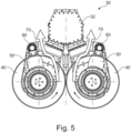
- a further preferred embodiment of the invention consists in that the at least one clearing plate and/or the plate holder are detachably attached and a connecting device is provided on the underside of the housing, with which at least one clearing plate can be attached directly to the housing.
- a particularly flexible arrangement of the clearing plates can be achieved in this way.
- the external clearing plates arranged on the plate holder can be partially or completely removed if necessary.
- clearing plates can be attached directly to the underside of the housing in a basically known manner. Screw connections or other easily detachable types of connection are particularly possible as connecting devices.
- the invention further comprises a trench wall milling device with a carrier device on which the trench wall milling machine according to the invention is arranged so as to be vertically movable with a lifting device.
- the carrier device can in particular be designed to be mobile with an undercarriage, in particular a crawler chassis, and an upper carriage rotatably mounted thereon.
- a mast or a boom arm can be provided on the upper carriage.
- a cable suspension or a rigid guide rod can be used as the lifting device, which is adjustable along the mast.
- the method according to the invention for creating a milling slot in the ground is characterized in that a trench wall cutter according to the invention or a trench wall cutter device according to the invention is used.
- a trench cutter or trench cutter device can be used. The previously described advantages can be achieved when carrying out the process.
- a preferred method variant according to the invention consists in that the at least one milling wheel is driven in rotation in a rotating device, in which milled soil material is guided by the at least one clearing plate through the passage between the housing and the clearing plate.
- a rotating device in which milled soil material is guided by the at least one clearing plate through the passage between the housing and the clearing plate.
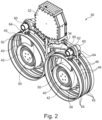
- a trench wall milling device 10 according to the invention with a carrier device 12 is shown in Figure 1
- the carrier device 12 can have an undercarriage 14 designed as a crawler chassis, on which a superstructure 16 can be rotatably mounted.
- a substantially vertical mast 18 can be adjustably mounted on the superstructure 16 via a linkage mechanism 17 with adjusting cylinders.
- a guide rod 22 can be arranged along the mast 18 as part of a lifting device 20.
- a trench wall cutter 30 according to the invention is attached to the lower end of the guide rod 22, which is described in more detail below.
- the guide rod 22 can be moved vertically along the mast 18 as part of the lifting device 20 via movable carriages 24 that can be connected to the guide rod 22 via clamping cylinders.
- the in Figure 1 The trench wall cutter 30 shown has two pairs of cutting wheels 40 which are arranged parallel to one another with horizontally arranged axes of rotation. On the outer circumference of the cutting wheels 40, indicated cutting teeth 44 are attached in a basically known manner.
Landscapes
- Engineering & Computer Science (AREA)
- Mining & Mineral Resources (AREA)
- Mechanical Engineering (AREA)
- Civil Engineering (AREA)
- General Engineering & Computer Science (AREA)
- Structural Engineering (AREA)
- Life Sciences & Earth Sciences (AREA)
- General Life Sciences & Earth Sciences (AREA)
- Paleontology (AREA)
- Processing Of Stones Or Stones Resemblance Materials (AREA)
- Excavating Of Shafts Or Tunnels (AREA)
- Pit Excavations, Shoring, Fill Or Stabilisation Of Slopes (AREA)
- Disintegrating Or Milling (AREA)
- Earth Drilling (AREA)
Priority Applications (8)
| Application Number | Priority Date | Filing Date | Title |
|---|---|---|---|
| EP22159510.1A EP4239130B1 (de) | 2022-03-01 | 2022-03-01 | Schlitzwandfräse und verfahren zum erstellen eines frässchlitzes im boden |
| PL22159510.1T PL4239130T3 (pl) | 2022-03-01 | 2022-03-01 | Frez do wykonywania ściany szczeliny i sposób wykonywania szczeliny frezowanej w gruncie |
| HUE22159510A HUE070624T2 (hu) | 2022-03-01 | 2022-03-01 | Membránfal fûrész és eljárás marórés kialakítására a talajban |
| ES22159510T ES3013816T3 (en) | 2022-03-01 | 2022-03-01 | Slurry wall cutter and method for creating a cut in the ground |
| CN202380021312.8A CN119234067A (zh) | 2022-03-01 | 2023-02-09 | 槽壁铣削机和用于在土壤中创建铣削槽的方法 |
| JP2024551995A JP2025508515A (ja) | 2022-03-01 | 2023-02-09 | 溝掘削機及び地面に掘削溝を形成する方法 |
| PCT/EP2023/053162 WO2023165796A1 (de) | 2022-03-01 | 2023-02-09 | Schlitzwandfräse und verfahren zum erstellen eines frässchlitzes im boden |
| US18/843,088 US20250179758A1 (en) | 2022-03-01 | 2023-02-09 | Trench cutter and method for making a cut trench in the ground |
Applications Claiming Priority (1)
| Application Number | Priority Date | Filing Date | Title |
|---|---|---|---|
| EP22159510.1A EP4239130B1 (de) | 2022-03-01 | 2022-03-01 | Schlitzwandfräse und verfahren zum erstellen eines frässchlitzes im boden |
Publications (3)
| Publication Number | Publication Date |
|---|---|
| EP4239130A1 EP4239130A1 (de) | 2023-09-06 |
| EP4239130C0 EP4239130C0 (de) | 2024-12-18 |
| EP4239130B1 true EP4239130B1 (de) | 2024-12-18 |
Family
ID=80623598
Family Applications (1)
| Application Number | Title | Priority Date | Filing Date |
|---|---|---|---|
| EP22159510.1A Active EP4239130B1 (de) | 2022-03-01 | 2022-03-01 | Schlitzwandfräse und verfahren zum erstellen eines frässchlitzes im boden |
Country Status (8)
| Country | Link |
|---|---|
| US (1) | US20250179758A1 (pl) |
| EP (1) | EP4239130B1 (pl) |
| JP (1) | JP2025508515A (pl) |
| CN (1) | CN119234067A (pl) |
| ES (1) | ES3013816T3 (pl) |
| HU (1) | HUE070624T2 (pl) |
| PL (1) | PL4239130T3 (pl) |
| WO (1) | WO2023165796A1 (pl) |
Families Citing this family (3)
| Publication number | Priority date | Publication date | Assignee | Title |
|---|---|---|---|---|
| EP4063568B1 (de) * | 2021-03-23 | 2023-10-04 | BAUER Maschinen GmbH | Messanordnung und abtragsvorrichtung mit einer messanordnung |
| WO2025056240A1 (de) * | 2023-09-11 | 2025-03-20 | Bauer Maschinen Gmbh | Schlitzwandfräsvorrichtung und verfahren zum fräsen eines frässchlitzes im boden |
| EP4600423A1 (de) * | 2024-02-07 | 2025-08-13 | BAUER Maschinen GmbH | Verfahren und vorrichtung zum erstellen eines gründungselementes im boden aus einem bodenmörtel |
Family Cites Families (3)
| Publication number | Priority date | Publication date | Assignee | Title |
|---|---|---|---|---|
| DE10308538C5 (de) | 2003-02-27 | 2014-11-06 | Bauer Maschinen Gmbh | Verfahren zum Herstellen einer Schlitzwand im Boden, Schlitzwandfräse und Schlitzwandfräsvorrichtung |
| EP3296468B1 (de) * | 2016-09-15 | 2019-11-06 | BAUER Maschinen GmbH | Verfahren und schlitzwandfräse zum erstellen eines schlitzes im boden |
| EP3543408B1 (de) * | 2018-03-21 | 2020-10-21 | BAUER Spezialtiefbau GmbH | Schlitzwandfräse und verfahren zum erstellen eines frässchlitzes im boden |
-
2022
- 2022-03-01 PL PL22159510.1T patent/PL4239130T3/pl unknown
- 2022-03-01 ES ES22159510T patent/ES3013816T3/es active Active
- 2022-03-01 HU HUE22159510A patent/HUE070624T2/hu unknown
- 2022-03-01 EP EP22159510.1A patent/EP4239130B1/de active Active
-
2023
- 2023-02-09 US US18/843,088 patent/US20250179758A1/en active Pending
- 2023-02-09 CN CN202380021312.8A patent/CN119234067A/zh active Pending
- 2023-02-09 JP JP2024551995A patent/JP2025508515A/ja active Pending
- 2023-02-09 WO PCT/EP2023/053162 patent/WO2023165796A1/de not_active Ceased
Also Published As
| Publication number | Publication date |
|---|---|
| HUE070624T2 (hu) | 2025-06-28 |
| WO2023165796A1 (de) | 2023-09-07 |
| EP4239130A1 (de) | 2023-09-06 |
| EP4239130C0 (de) | 2024-12-18 |
| US20250179758A1 (en) | 2025-06-05 |
| CN119234067A (zh) | 2024-12-31 |
| JP2025508515A (ja) | 2025-03-26 |
| PL4239130T3 (pl) | 2025-03-31 |
| ES3013816T3 (en) | 2025-04-15 |
Similar Documents
| Publication | Publication Date | Title |
|---|---|---|
| DE10308538C5 (de) | Verfahren zum Herstellen einer Schlitzwand im Boden, Schlitzwandfräse und Schlitzwandfräsvorrichtung | |
| EP4239130B1 (de) | Schlitzwandfräse und verfahren zum erstellen eines frässchlitzes im boden | |
| EP2324158B1 (de) | Baggeranbaufräse ausgestattet mit schneidköpfen und einer fräskette. | |
| DE68907339T2 (de) | Verfahren für den Schildvortrieb mit wählbarem Querschnitt und Maschine dafür. | |
| EP3296468B1 (de) | Verfahren und schlitzwandfräse zum erstellen eines schlitzes im boden | |
| EP2057348A1 (de) | Verfahren und vorrichtung fur die fräsende bearbeitung von materialen | |
| EP1640509A1 (de) | Vorrichtung und Verfahren zum Erstellen einer Schlitzwand im Erdboden | |
| EP3543408A1 (de) | Schlitzwandfräse und verfahren zum erstellen eines frässchlitzes im boden | |
| AT506122B1 (de) | Vortriebsmaschine | |
| AT510656A1 (de) | Vollschnittstreckenvortriebsmaschine | |
| EP4053342B1 (de) | Schlitzwandfräsvorrichtung und verfahren zum fräsen eines frässchlitzes im boden | |
| EP2423388A1 (de) | Verfahren und Vorrichtung zum Herstellen einer Schlitzwand | |
| DE2558250C2 (de) | Maschine zum Ausführen zweier paralleler Schnitte mit unterschiedlichem Abstand in Asphalt, Beton oder dergleichen | |
| DE202009002459U1 (de) | Mobiles Arbeitsgerät | |
| DE102022126170A1 (de) | System und verfahren zur materialentleerung in fräskammer | |
| EP4311882A1 (de) | Schlitzwandfräse und verfahren zum bilden eines frässchlitzes im boden | |
| DE102013003864A1 (de) | Straßenbaumaschine zum Bearbeiten von Straßenbelägen, insbesondere Straßenfräse | |
| DE4405303C1 (de) | Bodenbearbeitungsgerät | |
| EP3293313B1 (de) | Schneidwerkzeug | |
| DE1938818A1 (de) | Werkzeug fuer einen Drehkopf einer im Dauerbetrieb arbeitenden Bohr- oder Abbaumaschine | |
| EP1722186B1 (de) | Minenfräse für ein Minenräumfahrzeug | |
| WO2025056240A1 (de) | Schlitzwandfräsvorrichtung und verfahren zum fräsen eines frässchlitzes im boden | |
| DE8806088U1 (de) | Verfahrbarer Fugenschneider | |
| CH716467B1 (de) | Vorrichtung und Verfahren für den Abtrag von Bodenbelägen. | |
| DE2138012A1 (de) | Gesteinsbohrmaschine |
Legal Events
| Date | Code | Title | Description |
|---|---|---|---|
| STAA | Information on the status of an ep patent application or granted ep patent |
Free format text: STATUS: EXAMINATION IS IN PROGRESS |
|
| PUAI | Public reference made under article 153(3) epc to a published international application that has entered the european phase |
Free format text: ORIGINAL CODE: 0009012 |
|
| 17P | Request for examination filed |
Effective date: 20221207 |
|
| AK | Designated contracting states |
Kind code of ref document: A1 Designated state(s): AL AT BE BG CH CY CZ DE DK EE ES FI FR GB GR HR HU IE IS IT LI LT LU LV MC MK MT NL NO PL PT RO RS SE SI SK SM TR |
|
| GRAP | Despatch of communication of intention to grant a patent |
Free format text: ORIGINAL CODE: EPIDOSNIGR1 |
|
| STAA | Information on the status of an ep patent application or granted ep patent |
Free format text: STATUS: GRANT OF PATENT IS INTENDED |
|
| INTG | Intention to grant announced |
Effective date: 20240814 |
|
| GRAS | Grant fee paid |
Free format text: ORIGINAL CODE: EPIDOSNIGR3 |
|
| GRAA | (expected) grant |
Free format text: ORIGINAL CODE: 0009210 |
|
| STAA | Information on the status of an ep patent application or granted ep patent |
Free format text: STATUS: THE PATENT HAS BEEN GRANTED |
|
| AK | Designated contracting states |
Kind code of ref document: B1 Designated state(s): AL AT BE BG CH CY CZ DE DK EE ES FI FR GB GR HR HU IE IS IT LI LT LU LV MC MK MT NL NO PL PT RO RS SE SI SK SM TR |
|
| REG | Reference to a national code |
Ref country code: CH Ref legal event code: EP |
|
| REG | Reference to a national code |
Ref country code: DE Ref legal event code: R096 Ref document number: 502022002398 Country of ref document: DE |
|
| REG | Reference to a national code |
Ref country code: IE Ref legal event code: FG4D Free format text: LANGUAGE OF EP DOCUMENT: GERMAN |
|
| U01 | Request for unitary effect filed |
Effective date: 20241218 |
|
| U07 | Unitary effect registered |
Designated state(s): AT BE BG DE DK EE FI FR IT LT LU LV MT NL PT RO SE SI Effective date: 20250102 |
|
| PG25 | Lapsed in a contracting state [announced via postgrant information from national office to epo] |
Ref country code: HR Free format text: LAPSE BECAUSE OF FAILURE TO SUBMIT A TRANSLATION OF THE DESCRIPTION OR TO PAY THE FEE WITHIN THE PRESCRIBED TIME-LIMIT Effective date: 20241218 |
|
| REG | Reference to a national code |
Ref country code: ES Ref legal event code: FG2A Ref document number: 3013816 Country of ref document: ES Kind code of ref document: T3 Effective date: 20250415 |
|
| PG25 | Lapsed in a contracting state [announced via postgrant information from national office to epo] |
Ref country code: NO Free format text: LAPSE BECAUSE OF FAILURE TO SUBMIT A TRANSLATION OF THE DESCRIPTION OR TO PAY THE FEE WITHIN THE PRESCRIBED TIME-LIMIT Effective date: 20250318 |
|
| PG25 | Lapsed in a contracting state [announced via postgrant information from national office to epo] |
Ref country code: GR Free format text: LAPSE BECAUSE OF FAILURE TO SUBMIT A TRANSLATION OF THE DESCRIPTION OR TO PAY THE FEE WITHIN THE PRESCRIBED TIME-LIMIT Effective date: 20250319 |
|
| PGFP | Annual fee paid to national office [announced via postgrant information from national office to epo] |
Ref country code: PL Payment date: 20250207 Year of fee payment: 4 |
|
| PG25 | Lapsed in a contracting state [announced via postgrant information from national office to epo] |
Ref country code: RS Free format text: LAPSE BECAUSE OF FAILURE TO SUBMIT A TRANSLATION OF THE DESCRIPTION OR TO PAY THE FEE WITHIN THE PRESCRIBED TIME-LIMIT Effective date: 20250318 |
|
| PGFP | Annual fee paid to national office [announced via postgrant information from national office to epo] |
Ref country code: TR Payment date: 20250228 Year of fee payment: 4 |
|
| U20 | Renewal fee for the european patent with unitary effect paid |
Year of fee payment: 4 Effective date: 20250326 |
|
| REG | Reference to a national code |
Ref country code: HU Ref legal event code: AG4A Ref document number: E070624 Country of ref document: HU |
|
| PG25 | Lapsed in a contracting state [announced via postgrant information from national office to epo] |
Ref country code: SM Free format text: LAPSE BECAUSE OF FAILURE TO SUBMIT A TRANSLATION OF THE DESCRIPTION OR TO PAY THE FEE WITHIN THE PRESCRIBED TIME-LIMIT Effective date: 20241218 |
|
| PGFP | Annual fee paid to national office [announced via postgrant information from national office to epo] |
Ref country code: ES Payment date: 20250403 Year of fee payment: 4 |
|
| PG25 | Lapsed in a contracting state [announced via postgrant information from national office to epo] |
Ref country code: IS Free format text: LAPSE BECAUSE OF FAILURE TO SUBMIT A TRANSLATION OF THE DESCRIPTION OR TO PAY THE FEE WITHIN THE PRESCRIBED TIME-LIMIT Effective date: 20250418 |
|
| PGFP | Annual fee paid to national office [announced via postgrant information from national office to epo] |
Ref country code: HU Payment date: 20250224 Year of fee payment: 4 |
|
| PG25 | Lapsed in a contracting state [announced via postgrant information from national office to epo] |
Ref country code: SK Free format text: LAPSE BECAUSE OF FAILURE TO SUBMIT A TRANSLATION OF THE DESCRIPTION OR TO PAY THE FEE WITHIN THE PRESCRIBED TIME-LIMIT Effective date: 20241218 |
|
| PG25 | Lapsed in a contracting state [announced via postgrant information from national office to epo] |
Ref country code: CZ Free format text: LAPSE BECAUSE OF FAILURE TO SUBMIT A TRANSLATION OF THE DESCRIPTION OR TO PAY THE FEE WITHIN THE PRESCRIBED TIME-LIMIT Effective date: 20241218 |
|
| PG25 | Lapsed in a contracting state [announced via postgrant information from national office to epo] |
Ref country code: MC Free format text: LAPSE BECAUSE OF FAILURE TO SUBMIT A TRANSLATION OF THE DESCRIPTION OR TO PAY THE FEE WITHIN THE PRESCRIBED TIME-LIMIT Effective date: 20241218 |
|
| REG | Reference to a national code |
Ref country code: CH Ref legal event code: H13 Free format text: ST27 STATUS EVENT CODE: U-0-0-H10-H13 (AS PROVIDED BY THE NATIONAL OFFICE) Effective date: 20251023 |
|
| PLBE | No opposition filed within time limit |
Free format text: ORIGINAL CODE: 0009261 |
|
| STAA | Information on the status of an ep patent application or granted ep patent |
Free format text: STATUS: NO OPPOSITION FILED WITHIN TIME LIMIT |
|
| 26N | No opposition filed |
Effective date: 20250919 |