EP4238840B1 - Method for controlling hybrid vehicle and hybrid vehicle - Google Patents
Method for controlling hybrid vehicle and hybrid vehicle Download PDFInfo
- Publication number
- EP4238840B1 EP4238840B1 EP20959659.2A EP20959659A EP4238840B1 EP 4238840 B1 EP4238840 B1 EP 4238840B1 EP 20959659 A EP20959659 A EP 20959659A EP 4238840 B1 EP4238840 B1 EP 4238840B1
- Authority
- EP
- European Patent Office
- Prior art keywords
- electric power
- engine
- direct drive
- drive mode
- line
- Prior art date
- Legal status (The legal status is an assumption and is not a legal conclusion. Google has not performed a legal analysis and makes no representation as to the accuracy of the status listed.)
- Active
Links
Images


Classifications
-
- B—PERFORMING OPERATIONS; TRANSPORTING
- B60—VEHICLES IN GENERAL
- B60K—ARRANGEMENT OR MOUNTING OF PROPULSION UNITS OR OF TRANSMISSIONS IN VEHICLES; ARRANGEMENT OR MOUNTING OF PLURAL DIVERSE PRIME-MOVERS IN VEHICLES; AUXILIARY DRIVES FOR VEHICLES; INSTRUMENTATION OR DASHBOARDS FOR VEHICLES; ARRANGEMENTS IN CONNECTION WITH COOLING, AIR INTAKE, GAS EXHAUST OR FUEL SUPPLY OF PROPULSION UNITS IN VEHICLES
- B60K6/00—Arrangement or mounting of plural diverse prime-movers for mutual or common propulsion, e.g. hybrid propulsion systems comprising electric motors and internal combustion engines
- B60K6/20—Arrangement or mounting of plural diverse prime-movers for mutual or common propulsion, e.g. hybrid propulsion systems comprising electric motors and internal combustion engines the prime-movers consisting of electric motors and internal combustion engines, e.g. HEVs
- B60K6/22—Arrangement or mounting of plural diverse prime-movers for mutual or common propulsion, e.g. hybrid propulsion systems comprising electric motors and internal combustion engines the prime-movers consisting of electric motors and internal combustion engines, e.g. HEVs characterised by apparatus, components or means specially adapted for HEVs
- B60K6/38—Arrangement or mounting of plural diverse prime-movers for mutual or common propulsion, e.g. hybrid propulsion systems comprising electric motors and internal combustion engines the prime-movers consisting of electric motors and internal combustion engines, e.g. HEVs characterised by apparatus, components or means specially adapted for HEVs characterised by the driveline clutches
- B60K6/387—Actuated clutches, i.e. clutches engaged or disengaged by electric, hydraulic or mechanical actuating means
-
- B—PERFORMING OPERATIONS; TRANSPORTING
- B60—VEHICLES IN GENERAL
- B60K—ARRANGEMENT OR MOUNTING OF PROPULSION UNITS OR OF TRANSMISSIONS IN VEHICLES; ARRANGEMENT OR MOUNTING OF PLURAL DIVERSE PRIME-MOVERS IN VEHICLES; AUXILIARY DRIVES FOR VEHICLES; INSTRUMENTATION OR DASHBOARDS FOR VEHICLES; ARRANGEMENTS IN CONNECTION WITH COOLING, AIR INTAKE, GAS EXHAUST OR FUEL SUPPLY OF PROPULSION UNITS IN VEHICLES
- B60K6/00—Arrangement or mounting of plural diverse prime-movers for mutual or common propulsion, e.g. hybrid propulsion systems comprising electric motors and internal combustion engines
- B60K6/20—Arrangement or mounting of plural diverse prime-movers for mutual or common propulsion, e.g. hybrid propulsion systems comprising electric motors and internal combustion engines the prime-movers consisting of electric motors and internal combustion engines, e.g. HEVs
- B60K6/22—Arrangement or mounting of plural diverse prime-movers for mutual or common propulsion, e.g. hybrid propulsion systems comprising electric motors and internal combustion engines the prime-movers consisting of electric motors and internal combustion engines, e.g. HEVs characterised by apparatus, components or means specially adapted for HEVs
- B60K6/40—Arrangement or mounting of plural diverse prime-movers for mutual or common propulsion, e.g. hybrid propulsion systems comprising electric motors and internal combustion engines the prime-movers consisting of electric motors and internal combustion engines, e.g. HEVs characterised by apparatus, components or means specially adapted for HEVs characterised by the assembly or relative disposition of components
-
- B—PERFORMING OPERATIONS; TRANSPORTING
- B60—VEHICLES IN GENERAL
- B60K—ARRANGEMENT OR MOUNTING OF PROPULSION UNITS OR OF TRANSMISSIONS IN VEHICLES; ARRANGEMENT OR MOUNTING OF PLURAL DIVERSE PRIME-MOVERS IN VEHICLES; AUXILIARY DRIVES FOR VEHICLES; INSTRUMENTATION OR DASHBOARDS FOR VEHICLES; ARRANGEMENTS IN CONNECTION WITH COOLING, AIR INTAKE, GAS EXHAUST OR FUEL SUPPLY OF PROPULSION UNITS IN VEHICLES
- B60K6/00—Arrangement or mounting of plural diverse prime-movers for mutual or common propulsion, e.g. hybrid propulsion systems comprising electric motors and internal combustion engines
- B60K6/20—Arrangement or mounting of plural diverse prime-movers for mutual or common propulsion, e.g. hybrid propulsion systems comprising electric motors and internal combustion engines the prime-movers consisting of electric motors and internal combustion engines, e.g. HEVs
- B60K6/42—Arrangement or mounting of plural diverse prime-movers for mutual or common propulsion, e.g. hybrid propulsion systems comprising electric motors and internal combustion engines the prime-movers consisting of electric motors and internal combustion engines, e.g. HEVs characterised by the architecture of the hybrid electric vehicle
- B60K6/44—Series-parallel type
- B60K6/442—Series-parallel switching type
-
- B—PERFORMING OPERATIONS; TRANSPORTING
- B60—VEHICLES IN GENERAL
- B60W—CONJOINT CONTROL OF VEHICLE SUB-UNITS OF DIFFERENT TYPE OR DIFFERENT FUNCTION; CONTROL SYSTEMS SPECIALLY ADAPTED FOR HYBRID VEHICLES; ROAD VEHICLE DRIVE CONTROL SYSTEMS FOR PURPOSES NOT RELATED TO THE CONTROL OF A PARTICULAR SUB-UNIT
- B60W10/00—Conjoint control of vehicle sub-units of different type or different function
- B60W10/02—Conjoint control of vehicle sub-units of different type or different function including control of driveline clutches
-
- B—PERFORMING OPERATIONS; TRANSPORTING
- B60—VEHICLES IN GENERAL
- B60W—CONJOINT CONTROL OF VEHICLE SUB-UNITS OF DIFFERENT TYPE OR DIFFERENT FUNCTION; CONTROL SYSTEMS SPECIALLY ADAPTED FOR HYBRID VEHICLES; ROAD VEHICLE DRIVE CONTROL SYSTEMS FOR PURPOSES NOT RELATED TO THE CONTROL OF A PARTICULAR SUB-UNIT
- B60W10/00—Conjoint control of vehicle sub-units of different type or different function
- B60W10/04—Conjoint control of vehicle sub-units of different type or different function including control of propulsion units
- B60W10/06—Conjoint control of vehicle sub-units of different type or different function including control of propulsion units including control of combustion engines
-
- B—PERFORMING OPERATIONS; TRANSPORTING
- B60—VEHICLES IN GENERAL
- B60W—CONJOINT CONTROL OF VEHICLE SUB-UNITS OF DIFFERENT TYPE OR DIFFERENT FUNCTION; CONTROL SYSTEMS SPECIALLY ADAPTED FOR HYBRID VEHICLES; ROAD VEHICLE DRIVE CONTROL SYSTEMS FOR PURPOSES NOT RELATED TO THE CONTROL OF A PARTICULAR SUB-UNIT
- B60W10/00—Conjoint control of vehicle sub-units of different type or different function
- B60W10/04—Conjoint control of vehicle sub-units of different type or different function including control of propulsion units
- B60W10/08—Conjoint control of vehicle sub-units of different type or different function including control of propulsion units including control of electric propulsion units, e.g. motors or generators
-
- B—PERFORMING OPERATIONS; TRANSPORTING
- B60—VEHICLES IN GENERAL
- B60W—CONJOINT CONTROL OF VEHICLE SUB-UNITS OF DIFFERENT TYPE OR DIFFERENT FUNCTION; CONTROL SYSTEMS SPECIALLY ADAPTED FOR HYBRID VEHICLES; ROAD VEHICLE DRIVE CONTROL SYSTEMS FOR PURPOSES NOT RELATED TO THE CONTROL OF A PARTICULAR SUB-UNIT
- B60W20/00—Control systems specially adapted for hybrid vehicles
- B60W20/20—Control strategies involving selection of hybrid configuration, e.g. selection between series or parallel configuration
-
- B—PERFORMING OPERATIONS; TRANSPORTING
- B60—VEHICLES IN GENERAL
- B60W—CONJOINT CONTROL OF VEHICLE SUB-UNITS OF DIFFERENT TYPE OR DIFFERENT FUNCTION; CONTROL SYSTEMS SPECIALLY ADAPTED FOR HYBRID VEHICLES; ROAD VEHICLE DRIVE CONTROL SYSTEMS FOR PURPOSES NOT RELATED TO THE CONTROL OF A PARTICULAR SUB-UNIT
- B60W20/00—Control systems specially adapted for hybrid vehicles
- B60W20/10—Controlling the power contribution of each of the prime movers to meet required power demand
- B60W20/15—Control strategies specially adapted for achieving a particular effect
-
- B—PERFORMING OPERATIONS; TRANSPORTING
- B60—VEHICLES IN GENERAL
- B60W—CONJOINT CONTROL OF VEHICLE SUB-UNITS OF DIFFERENT TYPE OR DIFFERENT FUNCTION; CONTROL SYSTEMS SPECIALLY ADAPTED FOR HYBRID VEHICLES; ROAD VEHICLE DRIVE CONTROL SYSTEMS FOR PURPOSES NOT RELATED TO THE CONTROL OF A PARTICULAR SUB-UNIT
- B60W2510/00—Input parameters relating to a particular sub-units
- B60W2510/06—Combustion engines, Gas turbines
- B60W2510/0638—Engine speed
-
- B—PERFORMING OPERATIONS; TRANSPORTING
- B60—VEHICLES IN GENERAL
- B60W—CONJOINT CONTROL OF VEHICLE SUB-UNITS OF DIFFERENT TYPE OR DIFFERENT FUNCTION; CONTROL SYSTEMS SPECIALLY ADAPTED FOR HYBRID VEHICLES; ROAD VEHICLE DRIVE CONTROL SYSTEMS FOR PURPOSES NOT RELATED TO THE CONTROL OF A PARTICULAR SUB-UNIT
- B60W2510/00—Input parameters relating to a particular sub-units
- B60W2510/06—Combustion engines, Gas turbines
- B60W2510/0657—Engine torque
-
- B—PERFORMING OPERATIONS; TRANSPORTING
- B60—VEHICLES IN GENERAL
- B60W—CONJOINT CONTROL OF VEHICLE SUB-UNITS OF DIFFERENT TYPE OR DIFFERENT FUNCTION; CONTROL SYSTEMS SPECIALLY ADAPTED FOR HYBRID VEHICLES; ROAD VEHICLE DRIVE CONTROL SYSTEMS FOR PURPOSES NOT RELATED TO THE CONTROL OF A PARTICULAR SUB-UNIT
- B60W2510/00—Input parameters relating to a particular sub-units
- B60W2510/24—Energy storage means
- B60W2510/242—Energy storage means for electrical energy
- B60W2510/244—Charge state
-
- B—PERFORMING OPERATIONS; TRANSPORTING
- B60—VEHICLES IN GENERAL
- B60W—CONJOINT CONTROL OF VEHICLE SUB-UNITS OF DIFFERENT TYPE OR DIFFERENT FUNCTION; CONTROL SYSTEMS SPECIALLY ADAPTED FOR HYBRID VEHICLES; ROAD VEHICLE DRIVE CONTROL SYSTEMS FOR PURPOSES NOT RELATED TO THE CONTROL OF A PARTICULAR SUB-UNIT
- B60W2520/00—Input parameters relating to overall vehicle dynamics
- B60W2520/10—Longitudinal speed
-
- B—PERFORMING OPERATIONS; TRANSPORTING
- B60—VEHICLES IN GENERAL
- B60W—CONJOINT CONTROL OF VEHICLE SUB-UNITS OF DIFFERENT TYPE OR DIFFERENT FUNCTION; CONTROL SYSTEMS SPECIALLY ADAPTED FOR HYBRID VEHICLES; ROAD VEHICLE DRIVE CONTROL SYSTEMS FOR PURPOSES NOT RELATED TO THE CONTROL OF A PARTICULAR SUB-UNIT
- B60W2540/00—Input parameters relating to occupants
- B60W2540/10—Accelerator pedal position
-
- B—PERFORMING OPERATIONS; TRANSPORTING
- B60—VEHICLES IN GENERAL
- B60Y—INDEXING SCHEME RELATING TO ASPECTS CROSS-CUTTING VEHICLE TECHNOLOGY
- B60Y2200/00—Type of vehicle
- B60Y2200/90—Vehicles comprising electric prime movers
- B60Y2200/92—Hybrid vehicles
-
- Y—GENERAL TAGGING OF NEW TECHNOLOGICAL DEVELOPMENTS; GENERAL TAGGING OF CROSS-SECTIONAL TECHNOLOGIES SPANNING OVER SEVERAL SECTIONS OF THE IPC; TECHNICAL SUBJECTS COVERED BY FORMER USPC CROSS-REFERENCE ART COLLECTIONS [XRACs] AND DIGESTS
- Y02—TECHNOLOGIES OR APPLICATIONS FOR MITIGATION OR ADAPTATION AGAINST CLIMATE CHANGE
- Y02T—CLIMATE CHANGE MITIGATION TECHNOLOGIES RELATED TO TRANSPORTATION
- Y02T10/00—Road transport of goods or passengers
- Y02T10/60—Other road transportation technologies with climate change mitigation effect
- Y02T10/62—Hybrid vehicles
-
- Y—GENERAL TAGGING OF NEW TECHNOLOGICAL DEVELOPMENTS; GENERAL TAGGING OF CROSS-SECTIONAL TECHNOLOGIES SPANNING OVER SEVERAL SECTIONS OF THE IPC; TECHNICAL SUBJECTS COVERED BY FORMER USPC CROSS-REFERENCE ART COLLECTIONS [XRACs] AND DIGESTS
- Y02—TECHNOLOGIES OR APPLICATIONS FOR MITIGATION OR ADAPTATION AGAINST CLIMATE CHANGE
- Y02T—CLIMATE CHANGE MITIGATION TECHNOLOGIES RELATED TO TRANSPORTATION
- Y02T90/00—Enabling technologies or technologies with a potential or indirect contribution to GHG emissions mitigation
- Y02T90/10—Technologies relating to charging of electric vehicles
- Y02T90/16—Information or communication technologies improving the operation of electric vehicles
- Y02T90/167—Systems integrating technologies related to power network operation and communication or information technologies for supporting the interoperability of electric or hybrid vehicles, i.e. smartgrids as interface for battery charging of electric vehicles [EV] or hybrid vehicles [HEV]
-
- Y—GENERAL TAGGING OF NEW TECHNOLOGICAL DEVELOPMENTS; GENERAL TAGGING OF CROSS-SECTIONAL TECHNOLOGIES SPANNING OVER SEVERAL SECTIONS OF THE IPC; TECHNICAL SUBJECTS COVERED BY FORMER USPC CROSS-REFERENCE ART COLLECTIONS [XRACs] AND DIGESTS
- Y04—INFORMATION OR COMMUNICATION TECHNOLOGIES HAVING AN IMPACT ON OTHER TECHNOLOGY AREAS
- Y04S—SYSTEMS INTEGRATING TECHNOLOGIES RELATED TO POWER NETWORK OPERATION, COMMUNICATION OR INFORMATION TECHNOLOGIES FOR IMPROVING THE ELECTRICAL POWER GENERATION, TRANSMISSION, DISTRIBUTION, MANAGEMENT OR USAGE, i.e. SMART GRIDS
- Y04S30/00—Systems supporting specific end-user applications in the sector of transportation
- Y04S30/10—Systems supporting the interoperability of electric or hybrid vehicles
- Y04S30/12—Remote or cooperative charging
Definitions
- the present invention relates to a method for controlling a hybrid vehicle and a hybrid vehicle.
- the engine is further connected to a generator and used as an electric power generation source.
- a direct drive mode and a series mode, depending on a connection method of the engine.
- the engine In the direct drive mode, the engine is directly connected to driving wheels, and power of the engine is directly transmitted to the driving wheels, whereby the engine is used as a driving source.
- the engine In the series mode, the engine is connected to the generator, and the motor supplied with electric power generated by the generator is used as a driving source.
- WO2011/074483 discloses an example of a method for selecting a direct drive mode and a series mode in such a hybrid vehicle. According to WO2011/074483 , when the direct drive mode is selected and required output required for traveling and charging exceeds a sum of output of the motor and output of the engine, the mode is switched to the series mode.
- WO2015/185971A1 discloses a control device for a vehicle, which includes an ECU realizing different travelling modes.
- a rotation speed of the engine is determined according to a vehicle speed, for example, when high-speed charging is required, it is necessary to increase a torque in order to increase required charging electric power per unit time.
- the torque is increased while the rotation speed is kept constant, an operation efficiency of the engine deteriorates.
- the invention has been made in view of such a problem, and an object of the invention is to implement operation control of a hybrid vehicle capable of suppressing deterioration of a fuel consumption amount in an entire vehicle even under a condition in which a direct drive mode is selected.
- a method, according to claim 1, for controlling a hybrid vehicle is presented.
- an hybrid vehicle, according to claim 5 is presented. Preferred embodiments are disclosed in the dependent claims.
- FIG. 1 is a schematic configuration diagram of a vehicle 1.
- the vehicle 1 includes an engine 3, a generator 4, a battery 5, a motor 2, and a controller 7.
- the engine 3 is an internal combustion engine, and is, for example, a gasoline engine or a diesel engine.
- the generator 4 is a motor generator mainly used for electric power generation, and can perform electric power generation and power running.
- the generator 4 is driven by power of the engine 3 to perform electric power generation, and can assist a driving force of the engine 3 in addition to motoring of the engine 3 by performing power running using electric power of the battery 5, which will be described later.
- the battery 5 is charged with electric power generated by the generator 4 and electric power regenerated by the motor 2, which will be described later.
- the motor 2 is a motor generator mainly used for traveling.
- the motor 2 is driven by the electric power of the battery 5 to drive driving wheels 6, and co-rotates with rotation of the driving wheels 6 to generate electric power by deceleration energy during deceleration or the like.
- the controller 7 controls the motor 2, the engine 3, and the generator 4.
- the controller 7 is implemented by a microcomputer including a central processing unit (CPU), a read-only memory (ROM), a random access memory (RAM), and an input/output interface (I/O interface).
- the controller 7 may be implemented by a plurality of microcomputers.
- the vehicle 1 includes a power transmission path 24 that transmits power between the motor 2 and the driving wheels 6, a power transmission path 25 that transmits power between the engine 3 and the driving wheels 6, and a power transmission path 26 that transmits power between the engine 3 and the generator 4.
- the power transmission path 24 includes a first reduction gear 8 provided on a rotation shaft 2A of the motor 2, a second reduction gear 9 meshing with the first reduction gear 8, a differential gear 12 provided on a differential case 11, and a third reduction gear 10 provided coaxially with the second reduction gear 9 and meshing with the differential gear 12.
- the power transmission path 24 is provided with a first clutch mechanism 19 that switches between a state in which the first reduction gear 8 is rotatable relative to the rotation shaft 2A and a state in which the first reduction gear 8 is not rotatable relative to the rotation shaft 2A.
- the first clutch mechanism 19 is a so-called dog clutch that includes a first sleeve 20 axially slidably supported by the rotation shaft 2A, and an engagement portion 8A provided on the first reduction gear 8.
- the first sleeve 20 moves toward the first reduction gear 8, and a plurality of convex portions provided on the first sleeve 20 in a manner of protruding toward the engagement portion 8A and a plurality of convex portions provided on the engagement portion 8A in a manner of protruding toward the first sleeve 20 mesh with each other so as to be alternately arranged in a rotation direction, whereby the first sleeve 20 and the engagement portion 8A are brought into an engaged state.
- the first sleeve 20 moves in a direction opposite to the first reduction gear 8, and the engagement between the convex portions of the first sleeve 20 and the engagement portion 8A is released, whereby the first sleeve 20 and the engagement portion 8A are brought into a disengaged state. Movement of the first sleeve 20 is performed by an electric actuator.
- the power transmission path 25 includes a fourth reduction gear 16 provided on an output shaft 3A of the engine 3, a fifth reduction gear 17 meshing with the fourth reduction gear 16, the differential gear 12 provided on the differential case 11, and a sixth reduction gear 18 provided coaxially with the fifth reduction gear 17 and meshing with the differential gear 12.
- the power transmission path 25 is provided with a second clutch mechanism 21 that switches between a state in which the fourth reduction gear 16 is rotatable relative to the output shaft 3A and a state in which the fourth reduction gear 16 is not rotatable relative to the output shaft 3A.
- the second clutch mechanism 21 is a so-called dog clutch that includes a second sleeve 22 axially slidably supported by the output shaft 3A, and an engagement portion 16A provided on the fourth reduction gear 16.
- the second sleeve 22 moves toward the fourth reduction gear 16, and a plurality of convex portions provided on the second sleeve 22 in a manner of protruding toward the engagement portion 16A and a plurality of convex portions provided on the engagement portion 16A in a manner of protruding toward the second sleeve 22 mesh with each other so as to be alternately arranged in a rotation direction, whereby the second sleeve 22 and the engagement portion 16A are brought into an engaged state.
- the second sleeve 22 moves in a direction opposite to the fourth reduction gear 16, and the engagement between the convex portions of the second sleeve 22 and the engagement portion 16A is released, whereby the second sleeve 22 and the engagement portion 16A are brought into a disengaged state. Movement of the second sleeve 22 is performed by an electric actuator.
- the second clutch mechanism 21 When the second clutch mechanism 21 is in the engaged state, the power of the engine 3 is transmitted to the driving wheels 6. This state is referred to as a direct drive mode because the engine 3 is directly connected to the driving wheels 6 to cause the driving wheels 6 to operate. On the other hand, when the second clutch mechanism 21 is in the disengaged state, rotation of the output shaft 3A of the engine 3 is not transmitted to the fourth reduction gear 16, and thus transmission of power from the engine 3 to the driving wheels 6 is blocked.
- the power transmission path 26 includes a seventh reduction gear 13 provided on the output shaft 3A of the engine 3, an eighth reduction gear 14 meshing with the seventh reduction gear 13, and a ninth reduction gear 15 provided on a rotation shaft 4A of the generator 4.
- the power transmission path 26 does not include an element that blocks transmission of power, and the power transmission path 26 is always in a state in which power is transmitted. Therefore, in the direct drive mode, an excess of output of the engine 3 with respect to a driving force required for traveling is used for generating electric power in the generator 4.
- switching control is performed between a series mode, in which power is transmitted to the driving wheels 6 via the power transmission path 24 by connecting the engine 3 the generator 4 and the motor 2 in series, and the direct drive mode, in which power is transmitted to the driving wheels 6 via the power transmission path 25 by directly connecting the engine 3 to the driving wheels 6.
- the controller 7 switches between the series mode and the direct drive mode according to an operation state, specifically, according to a vehicle speed and the driving force.
- FIG. 2 is a diagram illustrating a power transmission state in the series mode.
- the series mode power is transmitted to the driving wheels 6 through the power transmission path 24. That is, in the series mode, power generated by the motor 2 is transmitted to the driving wheels 6 by bringing the first clutch mechanism 19 into the engaged state. At this time, the second clutch mechanism 21 is in the disengaged state.
- the power of the engine 3 is transmitted to the generator 4 via the power transmission path 26, the generator 4 generates electric power, and the battery 5 is charged with the generated electric power.
- a charging amount of the battery 5 is larger than an upper limit value (a charging stop threshold value) and it is not necessary to further charge the battery 5, the engine 3 may be stopped.
- FIG. 3 is a diagram illustrating a power transmission state in the direct drive mode.
- the direct drive mode power is transmitted to the driving wheels 6 through the power transmission path 25. That is, in the direct drive mode, power generated by the engine 3 is transmitted to the driving wheels 6 by bringing the second clutch mechanism 21 into the engaged state.
- the first clutch mechanism 19 In the direct drive mode, the first clutch mechanism 19 is in the disengaged state. If the first clutch mechanism 19 is brought into the engaged state in the direct drive mode, the motor 2 co-rotates with the rotation of the driving wheels 6, and an induced electromotive force is generated. When there is margin in a charging capacity of the battery 5, energy is regenerated by charging the battery 5 with the generated electric power. On the other hand, when there is no margin in the charging capacity of the battery 5, electric power generation resistance is a friction that hinders the rotation of the driving wheels 6, which causes a decrease in fuel consumption performance. Therefore, by bringing the first clutch mechanism 19 into the disengaged state in the direct drive mode, the decrease in the fuel consumption performance caused by the co-rotation of the motor 2 described above can be suppressed.
- the controller 7 selects one of the direct drive mode and the series mode based on a required driving force and a required vehicle speed of the vehicle 1 and in consideration of a fuel consumption amount of the engine 3 and the like.
- the selection control will be described with reference to FIG. 4 .
- FIG. 4 illustrates an operational view related to the engine 3.
- a horizontal axis indicates a vehicle speed (km/h)
- a vertical axis indicates a driving force (N) obtained by the motor 2 and/or the engine 3.
- N driving force
- Thin solid lines indicate both positive and negative driving forces obtained when the series mode is selected.
- the output of the engine 3 does not directly act on the wheels 6, and thus the driving force is obtained by output of the motor 2.
- the driving force obtained by the motor 2 is determined by an output torque and a gear ratio of the motor 2, and a diameter of the wheel.
- the engine 2 In the positive driving force range, the engine 2 is driven at constant high output) when the speed is relatively low (for example, about 60 km/h or less), and the output decreases as the speed increases after the speed achieves a medium speed range and a high speed range (for example, about 60 km/h to 150 km/h). It is known that an output characteristic of the motor 2 is poor in an ultrahigh speed range, and thus the output rapidly decreases and becomes zero after the speed achieves an upper limit speed (for example, about 150 km/h or more). As compared with the positive output range, the negative output range has a change characteristic similar to that of the positive output range, but an absolute value is smaller.
- a thick two-dot chain line indicates a wide open slot (WOT) line.
- the WOT line indicates a driving force of the vehicle 1 obtained when the engine 3 is driven at maximum output in the direct drive mode.
- the WOT line has a change characteristic similar to that of the ⁇ line, and indicates output larger than that of the ⁇ line as a whole.
- a thin one-dot chain line is referred to as an ⁇ + GEN line.
- the ⁇ + GEN line indicates a driving force obtained when the generator 4 is caused to perform power running at maximum output and the engine 3 is driven with the optimum fuel consumption during the direct drive mode operation. Therefore, the driving force indicated by the ⁇ + GEN line corresponds to a sum of the maximum output of the generator 4 that performs the power assist and the output of the engine 3 driven with the optimum fuel consumption.
- a thin two-dot chain line is referred to as a WOT + GEN line.
- the WOT + GEN line indicates a driving force obtained when the engine 3 is driven at the maximum output during the direct drive mode operation.
- the driving force indicated by the WOT + GEN line corresponds to a sum of the maximum output of the generator 4 that performs the power assist and the maximum output of the engine 3. Therefore, the WOT + GEN line indicates a maximum driving force that can be obtained by the driving wheels 6 in the direct drive mode.
- a thick solid line is referred to as a road/load (R/L) line.
- the R/L line indicates a driving force required for constant speed traveling in a case in which a traveling road is flat. According to the R/L line, the driving force required for the constant speed traveling increases as the vehicle speed increases. This is because traveling resistance such as air resistance and road surface resistance increases in proportion to the vehicle speed.
- the direct drive mode is a mode in which the driving force is obtained by the engine 3, it is desirable to select the direct drive mode in the medium speed range and the high speed range than the low speed range.
- the WOT + GEN line indicates upper limit output in the direct drive mode. Therefore, the direct drive mode is selected in principle in the region hatched upward to the right, that is, in a region that includes the medium speed range and the high speed range in which a driving efficiency of the engine 3 is high in the horizontal axis, and that is below the WOT + GEN line on which the maximum output can be obtained in the vertical axis.
- a lower limit speed in the region in which the direct drive mode is selected is mainly due to a performance of the engine 3, and is mainly determined by a design.
- the series mode is selected in principle. As will be described later, even in the hatched region, the series mode may be selected as illustrated in FIGS. 8 and 9 according to processing illustrated in FIG. 5 .
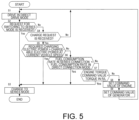
- FIG. 5 is a diagram illustrating the control for switching from the direct drive mode to the series mode performed by the controller 7. It is assumed that, in a previous stage where the switching control is performed, in the operational view illustrated in FIG. 4 , an operating point is in the region hatched upward to the right, and the direct drive mode is selected. In the following, a description will be given of conditions under which the mode is switched to the series mode in a state in which the direct drive mode is selected as described above.
- step S1 the controller 7 determines the required driving force and the required vehicle speed of the vehicle 1 according to a detected engine rotation speed, a depression amount of an accelerator pedal, and the like. It is assumed that in this figure, the controller 7 selects the direct drive mode based on the required driving force, the required vehicle speed, and the operational view illustrated in FIG. 4 .
- the direct drive mode is set.
- the series mode is set and the engine 3 is stopped.
- step S2 the controller 7 determines whether a request for switching to the series mode is received from a host controller or the like. For example, in a case in which a traveling route determined in a navigation system includes an uphill slope which requires large electric power consumption, a residential area where the engine 3 needs to be stopped for noise reduction, or the like, the charging amount of the battery 5 needs to be increased in advance, and thus the request for switching to the series mode is transmitted from the host controller.
- step S3 When the controller 7 receives the request for switching to the series mode (S2: Yes), the controller 7 then performs processing of step S3.
- step S4 When the controller 7 does not receive the request for switching to the series mode (S2: No), the controller 7 then performs processing of step S4.
- step S3 the controller 7 selects the series mode.
- the motor 2 is connected to the driving wheels 6 by releasing the second clutch mechanism 21 and bringing the first clutch mechanism 19 into the connected state.
- the series mode is always selected.
- step S4 the controller 7 determines whether a charge request requesting an increase in the charging amount of the battery 5 is received from a user.
- the charge request is made by a button operation based on a determination of the user when it is predicted that the electric power consumption will increase before traveling on the uphill slope.
- the controller 7 then performs determination processing of step S5 when the charge request is received (S4: Yes). When the charge request is not received (S4: No), the controller 7 then performs the processing of step S1 in order to continue the operation in the direct drive mode.
- step S5 the controller 7 obtains a required charging speed (a rate of increase in the charging amount) based on a state (a current temperature, the charging amount) of the battery 5, and calculates required charging electric power per unit time required to implement the charging speed. Then, the controller 7 determines whether the required charging electric power per unit time exceeds chargeable electric power per unit time that can be implemented at a current vehicle speed. When the required charging electric power per unit time exceeds the chargeable electric power per unit time, the direct drive mode is switched to the series mode to achieve quick charging according to the charge request in order to exceed the required charging speed.
- the required charging electric power per unit time and the chargeable electric power per unit time are simply referred to as required charging electric power and chargeable electric power, respectively.
- the chargeable electric power is determined according to the difference between the WOT line and the R/L line at a certain vehicle speed. Therefore, the controller 7 obtains a driving force difference by subtracting the driving force required for the constant speed traveling of the vehicle 1 (the R/L line) from the maximum driving force of the engine 3 (the WOT line), and calculates the chargeable electric power based on the driving force difference.
- the controller 7 determines that quick charging cannot be performed while maintaining the vehicle speed in the direct drive mode, and it is necessary to change the mode to the series mode, and then performs the processing of step S3.
- the controller 7 further performs determination processing of step S6.
- step S6 the controller 7 determines whether an operation efficiency in the series mode exceeds an operation efficiency in the direct drive mode based on an assumption that the required charging electric power obtained in step S5 is implemented.
- the engine 3 In the direct drive mode, the engine 3 is connected to the driving wheels 6, and the rotation speed is determined according to the vehicle speed, and thus it is necessary to control the output of the engine 3 by the torque.
- the operation efficiency of the engine 3 in the direct drive mode in which only the torque is changed may be less than the operation efficiency of the engine 3 in the series mode in which the rotation speed and the torque can be freely selected. Therefore, fuel consumption rates, which indicate the operation efficiencies of the engine 3 in both modes, are compared, and a mode in which the operation efficiency is high and the fuel consumption rate is small is selected.
- step S3 When a fuel consumption rate in the series mode is smaller than a fuel consumption rate in the direct drive mode (the operation efficiency is high) (S6: Yes) under a condition assuming that the required charging electric power is obtained at a predetermined speed, the controller 7 then performs the processing of step S3 in order to change the mode to the series mode.
- the controller 7 When the fuel consumption rate in the series mode is not smaller than the fuel consumption rate in the direct drive mode (the operation efficiency is low) (S6: No), the controller 7 further performs determination processing of step S7. Details of the determination processing using the fuel consumption rate will be described later with reference to FIG. 6 .
- step S7 the controller 7 calculates an output command value (a torque command value) for the engine 3 required for implementing the required charging electric power at a current vehicle speed when the direct drive mode is selected. Then, the controller 7 determines whether the output command value for the engine 3 exceeds the torque required for traveling indicated by the R/L line.
- a torque command value a torque command value
- the controller 7 determines that the charging cannot be performed while maintaining the speed in the direct drive mode, and then performs the processing of step S3 in order to change the mode to the series mode.
- the controller 7 then performs processing of step S8 in order to operate in the direct drive mode.
- step S8 the controller 7 sets the output command value obtained in step S7 as a command value for the engine 3. Accordingly, an excess of the output of the engine 3 with respect to the output indicated by the R/L line required for traveling is used for generating electric power, and the battery 5 can be charged.
- step S9 the controller 7 sets the required generated electric power as a command value for the generator 4.
- the motor 2 co-rotates with the driving wheels 6, and thus electric power corresponding to the required generated electric power can be generated.
- a thick solid line, an one-dot chain line, and a two-dot chain line, which are upward to the right, correspond to the R/L line (when the output of the engine 3 is the output required for the constant speed traveling), the ⁇ line (when the engine 3 is driven with the optimum fuel consumption), and the WOT line (when the engine 3 is driven at the maximum output) illustrated in FIG. 4 , respectively, and indicate sets of operating points in the respective states.
- Thin lines downward to the right each indicate output corresponding to the operating point of the engine 3.
- An intersection point of the right-upward thick line and the right-downward thin line makes it possible to know a change in the output of the engine 3 according to a driving state of the engine 3 (the ⁇ line, the WOT line, or the R/L line) determined by the right-upward thick line.
- the output of the engine 3 indicated by the right-downward thin line is proportional to a product of the torque and the rotation speed of the engine 3, the output increases as the torque increases, and the output increases as the rotation speed increases.
- the rotation speed decreases as the torque increases.
- Electric power charged to the battery 5 in the direct drive mode corresponds to the difference between the line (the ⁇ line, the WOT line) indicating the operating point of the engine 3 and the line (the R/L line) indicating the output required for traveling.
- the chargeable electric power when the engine 3 is driven with the optimum fuel consumption corresponds to the difference between the ⁇ line and the R/L line on the vertical axis corresponding to the predetermined speed.
- the chargeable electric power when the engine 3 is driven at the maximum output corresponds to the difference between the WOT line and the R/L line.
- step S6 in FIG. 5 the engine rotation speeds corresponding to traveling at the vehicle speeds V1 to V3 are indicated along the vertical axis.
- the vehicle speeds V1 to V3 are also illustrated in FIG. 4 .
- a difference (8 kW) between output (about 12 kW) corresponding to an operating point P11 on the ⁇ line and output (4 kW) corresponding to an operating point P12 on the R/L line indicates charging electric power to the battery 5.
- a fuel consumption rate in this case is determined by an equal fuel consumption line, and the operating point P11 is inside a W1 line, and thus it can be understood that a fuel consumption rate of the operating point P1 is smaller than a value corresponding to W1.
- the engine 3 is not connected to the driving wheels 6, and thus the engine 3 can be operated at any rotation speed regardless of the vehicle speed.
- an operating point P13 for obtaining electric power (8 kW) that can be generated in the direct drive mode is determined.
- a fuel consumption rate in this case is smaller than the value corresponding to W1, as in the case of the operating point P1.
- the fuel consumption rates in both the direct drive mode (P11) and the series mode (P13) are less than the value corresponding to W1, but the direct drive mode (P11) is more inside the equal fuel consumption line of W1 than the series mode (P13), and the fuel consumption rate is small (the operation efficiency is high). Therefore, when the required charging electric power is 8 kW, the direct drive mode is selected based on the comparison result according to the fuel consumption rate (S6: No), and thereafter, further determination processing (S7) in the direct drive mode is performed.
- the fuel consumption rate in the series mode (P22) is smaller than that in the direct drive mode (P21) (the operation efficiency is high) (S6: Yes), and thus the series mode is selected thereafter (S3).
- a case in which a fuel consumption rate in the series mode is smaller than that in the direct drive mode will be examined.
- the operating point of the engine 3 is P31. This is because output at the operating point P31 is 22 kW, output at an operating point P32 on the R/L line is 20 kW when the vehicle speed is V2, and an excess of 2 kW of the output at the operating point P31 with respect to the output at the operating point P32 is generated electric power.
- a fuel consumption rate in this case can be understood from the equal fuel consumption line corresponding to the operating point P31, and is about the value corresponding to W1.
- the operating point of the engine 3 for obtaining the charging electric power of 2 kW is an operating point P33 on the ⁇ line.
- a fuel consumption rate in this case is larger than the value corresponding to W1.
- the fuel consumption rate in the series mode (P13) is larger than that in the direct drive mode (P11) (the operation efficiency is low) (S6: No), and thus further determination processing (S7) in the direct drive mode is performed thereafter.
- Chargeable electric power in the case of traveling at the vehicle speed of V2 can be obtained based on a difference (10 kW) between an operating point P34 (30 kW) on the WOT line and the operating point P32 (20 kW) on the R/L line.
- the chargeable electric power can be indicated by the difference between the WOT line and the R/L line.
- the output indicated by both the WOT line and the R/L line increase as the vehicle speed increases, but an increase rate of the R/L line is larger than that of the WOT line. Therefore, since the chargeable electric power (WOT line - R/L line) decreases as the vehicle speed increases, the chargeable electric power is likely to be less than the required generated electric power (S5: Yes), and the series mode is likely to be selected. This relation will be described with reference to FIGS. 7 and 8 .
- FIGS. 7 and 8 illustrate operational views similar to that in FIG. 4 .
- a region in which the direct drive mode is selected in principle as illustrated in FIG. 4 in an example in which a required electric power generation amount is a predetermined value, a region in which the required charging electric power exceeds the chargeable electric power at the current vehicle speed (step S5: Yes in FIG. 5 ), and the series mode (S3) can be selected is hatched in a grid pattern.
- a region in which the required charging electric power is less than the chargeable electric power at the current vehicle speed step S5: No
- charging is possible in the direct drive mode is hatched upward to the right.
- the series mode is selected in principle as in FIG. 4 .
- FIG. 7 illustrates an example in which the required generated electric power is 14 kW.
- the chargeable electric power is 14 kW, which is equal to the required generated electric power in this example.
- the required generated electric power corresponds to the output difference between the operating points P21 and P11 in FIG. 6 , and in a situation of traveling at the vehicle speed of V1 when the direct drive mode is selected, the chargeable electric power obtained when the engine 3 is driven at the maximum driving force (the WOT) is 14 kW, which is equal to the required generated electric power.
- the chargeable electric power in the direct drive mode is less than the required generated electric power (14 kW), and thus the series mode is selected to implement the required charging electric power.
- the chargeable electric power corresponds to the difference between the WOT line and the R/L line, this means that since the chargeable electric power corresponding to the output difference between the WOT line and the R/L line is less than 14 kW, which is the required charging electric power, in the region hatched in a grid pattern in which the vehicle speed exceeds V1, the series mode is selected instead of the direct drive mode.
- FIG. 8 illustrates an example in which the required generated electric power is 10 kW.
- the chargeable electric power is 10 kW, which is equal to the required generated electric power in this example.
- the required generated electric power corresponds to the output difference between the operating points P34 and P31 in FIG. 6 , and in a situation of traveling at the vehicle speed of V2 when the direct drive mode is selected, the chargeable electric power obtained when the engine 3 is driven at the maximum driving force (the WOT) is 14 kW, which is equal to the required generated electric power. That is, when the vehicle speed exceeds V2, the chargeable electric power in the direct drive mode is less than the required generated electric power (10 kW), and thus the series mode is selected to implement the required charging electric power.
- a size of the region hatched upward to the right in which the direct drive mode is selected changes in a speed direction according to the required generated electric power.
- the region is longer in the speed direction as the required generated electric power is smaller. This is because the output of the engine 3 in the direct drive mode and the output required for the constant speed traveling (the R/L line) both result from the speed, and thus generatable electric power, which is the difference between the output of the engine 3 and the output required for the constant speed traveling, also changes according to the speed.
- the upper limit speed in the region in which the direct drive mode is selected increases as the required generated electric power decreases.
- a first factor is that the chargeable electric power easily exceeds the required generated electric power in a state in which the direct drive mode is selected as the required generated electric power decreases.
- a second factor is that the rate of increase according to the speed in the R/L line is larger than that in the ⁇ line, and thus the generatable electric power corresponding to the difference between the R/L line and the ⁇ line decreases as the speed increases. Due to these two factors, the chargeable electric power may decrease as the required generated electric power decreases, and thus charging electric power exceeding the required generated electric power can be obtained even at a higher speed, and as a result, the upper limit speed in the direct drive mode increases.
- the lower limit speed of the region in which the direct drive mode is selected is mainly due to the engine 3 and is mainly determined by the design, the lower limit speed does not change according to the required generated electric power. Therefore, the region hatched upward to the right in which the direct drive mode is selected changes in the speed direction according to the required generated electric power, and in detail, the upper limit speed decreases as the required generated electric power increases.
- the series mode is selected.
- the mode is selected according to a traveling state of the vehicle 1, when the direct drive mode is selected, there is an advantage in the fuel consumption amount or the like over the series mode.
- the rotation speed of the engine 3 is determined according to the vehicle speed, even if the engine 3 is operated at the maximum output, the battery 5 may not be charged with charging electric power exceeding the required charging electric power per unit time. Therefore, when the required charging electric power exceeds the threshold value, the charging electric power exceeding the required charging electric power per unit time cannot be generated in the direct drive mode, and it is determined that the battery 5 cannot be charged at a required speed, and thus the series mode is selected.
- the direct drive mode can be selected if the required charging electric power is less than the threshold value and quick charging is not required.
- opportunities to select the direct drive mode appropriately selected according to the traveling state of the vehicle 1 increases, and thus the total fuel consumption amount can be reduced.
- the controller 7 when the battery 5 is charged in the direct drive mode, the controller 7 obtains the chargeable electric power per unit time by subtracting the output required for traveling (the R/L mode) from the maximum output of the engine 3 (the WOT line) operating at a rotation speed corresponding to the vehicle speed.
- the controller 7 determines that the chargeable electric power is less than the required charging electric power (S5: Yes)
- the controller 7 disconnects the engine 3 from the driving wheels 6 and causes the vehicle 1 to be driven in the series mode because it is determined that the battery 5 cannot be charged at the required speed.
- the engine 3 since the engine 3 is connected to the wheels and the rotation speed is limited, it is necessary to control the generated electric power only by the torque. As a result, since the engine 3 has an upper limit in the generatable electric power (the WOT line), there is also an upper limit in the chargeable electric power obtained by subtracting the output required for traveling from the generatable electric power. When the chargeable electric power is less than the required charging electric power, the battery 5 cannot be charged at the required charging speed in the direct drive mode, and thus the series mode is selected.
- the battery can be charged in the direct drive mode unless the required charging electric power exceeds the generatable electric power.
- opportunities to select the direct drive mode appropriately selected according to the traveling state of the vehicle 1 increases, and thus the total fuel consumption amount can be reduced.
- the series mode is selected (S7).
- the fuel consumption rate increases in a case in which the engine 3 operates at the maximum output (the WOT line) due to the connection of the engine 3 to the wheels.
- the series mode since there is no limitation due to the operation state of the vehicle 1, the operating point can be freely selected. Therefore, when the fuel consumption rate in the direct drive mode is smaller than the fuel consumption rate in the series mode (S6: Yes) on the assumption that the required generated electric power is implemented, the series mode is selected (S7), whereby the total fuel consumption amount can be reduced.
- an electric power generation efficiency in the series mode is relatively higher than that in the direct drive mode. Therefore, when the series mode is selected in consideration of the minimization of the fuel consumption amount, the region in which the series mode is selected may be larger and the region in which the direct drive mode is selected may be narrower as the required charging speed (the required charging electric power per unit time) is higher.
- the series mode is selected in consideration of the electric power generation efficiency, the driving force obtained in the series mode is limited, and thus there is a concern that switching between the series mode and the direct drive mode may occur according to a change in the required driving force.
- the region in which the direct drive mode is selected that is, the region in which it is determined that the required charging electric power exceeds the chargeable electric power in the case in which the direct drive mode is selected, is narrower according to the required charging electric power, opportunities to appropriately select the direct drive mode can be increased according to the required charging electric power.
- the lower limit speed at which the series mode is selected increases as the required charging electric power decreases, and thus opportunities to select the series mode decreases. This means that opportunities to select the direct drive mode appropriately selected according to the traveling state of the vehicle 1 increases, and thus the total fuel consumption amount can be reduced.
- the controller 7 stops the engine 3 when the charging amount of the battery 5 exceeds the upper limit value (the charging stop threshold value) in a state in which the series mode is selected. This is because it is not necessary to charge the battery 5 anymore when the charging amount of the battery 5 exceeds the threshold value. In this way, the total fuel consumption amount can be reduced.
Landscapes
- Engineering & Computer Science (AREA)
- Chemical & Material Sciences (AREA)
- Combustion & Propulsion (AREA)
- Transportation (AREA)
- Mechanical Engineering (AREA)
- Automation & Control Theory (AREA)
- Electric Propulsion And Braking For Vehicles (AREA)
- Hybrid Electric Vehicles (AREA)
Applications Claiming Priority (1)
| Application Number | Priority Date | Filing Date | Title |
|---|---|---|---|
| PCT/IB2020/000880 WO2022090755A1 (ja) | 2020-10-28 | 2020-10-28 | ハイブリッド車両の制御方法、及び、ハイブリッド車両 |
Publications (3)
| Publication Number | Publication Date |
|---|---|
| EP4238840A1 EP4238840A1 (en) | 2023-09-06 |
| EP4238840A4 EP4238840A4 (en) | 2024-06-19 |
| EP4238840B1 true EP4238840B1 (en) | 2025-05-07 |
Family
ID=81383083
Family Applications (1)
| Application Number | Title | Priority Date | Filing Date |
|---|---|---|---|
| EP20959659.2A Active EP4238840B1 (en) | 2020-10-28 | 2020-10-28 | Method for controlling hybrid vehicle and hybrid vehicle |
Country Status (5)
| Country | Link |
|---|---|
| US (1) | US11981320B2 (https=) |
| EP (1) | EP4238840B1 (https=) |
| JP (1) | JP7386355B2 (https=) |
| CN (1) | CN116472192B (https=) |
| WO (1) | WO2022090755A1 (https=) |
Families Citing this family (1)
| Publication number | Priority date | Publication date | Assignee | Title |
|---|---|---|---|---|
| CN117261602A (zh) * | 2023-11-13 | 2023-12-22 | 浙江飞碟汽车制造有限公司 | 一种串联式混合动力电动汽车增程器发电性能监控方法 |
Family Cites Families (37)
| Publication number | Priority date | Publication date | Assignee | Title |
|---|---|---|---|---|
| WO2011074482A1 (ja) * | 2009-12-16 | 2011-06-23 | 本田技研工業株式会社 | ハイブリッド車両及びその制御方法 |
| CN104118424B (zh) * | 2009-12-16 | 2017-06-20 | 本田技研工业株式会社 | 混合动力车辆及其控制方法 |
| CN102770294B (zh) * | 2010-01-13 | 2015-09-16 | 菲斯科汽车科技集团有限公司 | 控制汽车驱动系统中的直接电连接和耦合的系统和方法 |
| JP5510662B2 (ja) * | 2010-09-09 | 2014-06-04 | 三菱自動車工業株式会社 | 車両の制御装置 |
| KR20140060334A (ko) * | 2011-09-05 | 2014-05-19 | 혼다 기켄 고교 가부시키가이샤 | 하이브리드 차량의 제어 장치 및 제어 방법 |
| JP6070934B2 (ja) * | 2012-12-21 | 2017-02-01 | 三菱自動車工業株式会社 | ハイブリッド車の走行モード切換制御装置 |
| JP6119966B2 (ja) * | 2012-12-21 | 2017-04-26 | 三菱自動車工業株式会社 | ハイブリッド車の走行モード切換制御装置 |
| JP6274386B2 (ja) * | 2013-01-09 | 2018-02-07 | 三菱自動車工業株式会社 | ハイブリッド車のエンジン運転制御装置 |
| US9457798B2 (en) * | 2013-01-11 | 2016-10-04 | Honda Motor Co., Ltd. | Hybrid vehicle and method for controlling same |
| JPWO2014109063A1 (ja) | 2013-01-11 | 2017-01-19 | 本田技研工業株式会社 | ハイブリッド車両及びその制御方法 |
| US9045136B2 (en) * | 2013-02-08 | 2015-06-02 | Efficient Drivetrains, Inc. | Systems and methods for implementing dynamic operating modes and control policies for hybrid electric vehicles |
| EP2965942A4 (en) * | 2013-03-07 | 2016-11-30 | Honda Motor Co Ltd | POWER SUPPLY CONTROL DEVICE AND POWER SUPPLY CONTROL METHOD |
| WO2015068482A1 (ja) * | 2013-11-11 | 2015-05-14 | 本田技研工業株式会社 | ハイブリッド車両の制御装置 |
| CN104276031B (zh) * | 2014-01-30 | 2016-01-13 | 比亚迪股份有限公司 | 车辆及其驱动控制方法 |
| JP6172008B2 (ja) * | 2014-03-24 | 2017-08-02 | トヨタ自動車株式会社 | ハイブリッド車両 |
| JP6135603B2 (ja) * | 2014-06-02 | 2017-05-31 | トヨタ自動車株式会社 | 車両の制御装置 |
| JP6471859B2 (ja) * | 2015-03-04 | 2019-02-20 | 三菱自動車工業株式会社 | ハイブリッド車両の制御装置 |
| JP6269539B2 (ja) * | 2015-03-09 | 2018-01-31 | トヨタ自動車株式会社 | ハイブリッド車両 |
| EP3305615B1 (en) * | 2015-06-03 | 2019-09-25 | Nissan Motor Co., Ltd. | Mode transition control device for hybrid vehicle |
| MX366082B (es) * | 2015-06-09 | 2019-06-27 | Nissan Motor | Dispositivo de control de transicion de modo para vehiculo hibrido. |
| JP2017056836A (ja) | 2015-09-16 | 2017-03-23 | スズキ株式会社 | 車両用駆動制御装置 |
| CN106853819B (zh) * | 2015-12-09 | 2019-05-24 | 上海汽车集团股份有限公司 | 一种hcu及离合器工作模式切换的控制方法 |
| JP2018134942A (ja) * | 2017-02-21 | 2018-08-30 | 株式会社豊田中央研究所 | ハイブリッド車両の制御装置 |
| DE102017208654A1 (de) * | 2017-05-22 | 2018-11-22 | Volkswagen Aktiengesellschaft | Verfahren zum Steuern einer Antriebseinrichtung eines Hybridfahrzeuges und Hybridfahrzeug |
| DE102017208656A1 (de) * | 2017-05-22 | 2018-11-22 | Volkswagen Aktiengesellschaft | Verfahren zum Steuern einer Antriebseinrichtung eines Hybridfahrzeuges und Hybridfahrzeug |
| US10569760B2 (en) * | 2017-06-09 | 2020-02-25 | Ford Global Technologies, Llc | Systems and methods for battery charging in a hybrid vehicle |
| JP6881210B2 (ja) * | 2017-10-11 | 2021-06-02 | トヨタ自動車株式会社 | ハイブリッド車両の制御装置 |
| DE102017221495A1 (de) * | 2017-11-30 | 2019-06-06 | Volkswagen Aktiengesellschaft | Verfahren zum Betreiben eines hybriden Antriebsstrangs eines Kraftfahrzeugs und Kraftfahrzeug |
| JP6660929B2 (ja) * | 2017-12-04 | 2020-03-11 | 本田技研工業株式会社 | 車両の制御装置 |
| FR3077257B1 (fr) * | 2018-01-30 | 2020-01-03 | Psa Automobiles Sa | Systeme et procede de pilotage de l’energie fournie au circuit electrique d’un vehicule hybride, et vehicule automobile les incorporant |
| JP6939675B2 (ja) * | 2018-03-27 | 2021-09-22 | 株式会社豊田自動織機 | 発電機を備える車両 |
| JP7091948B2 (ja) * | 2018-08-30 | 2022-06-28 | トヨタ自動車株式会社 | ハイブリッド車両の制御装置 |
| JP7298179B2 (ja) * | 2019-02-18 | 2023-06-27 | 日産自動車株式会社 | 電動車両の制御方法および電動車両の駆動システム |
| KR102570749B1 (ko) * | 2019-04-11 | 2023-08-28 | 현대자동차주식회사 | 차량 및 차량의 제어방법 |
| WO2021038266A1 (ja) * | 2019-08-28 | 2021-03-04 | 日産自動車株式会社 | 動力伝達装置 |
| CN112124297B (zh) * | 2020-09-07 | 2022-04-29 | 长城汽车股份有限公司 | 混合动力车辆的驱动方法、装置和车辆 |
| CN116472418B (zh) * | 2020-11-18 | 2026-01-02 | 日产自动车株式会社 | 车辆的离合器控制方法以及车辆的离合器控制装置 |
-
2020
- 2020-10-28 US US18/034,154 patent/US11981320B2/en active Active
- 2020-10-28 CN CN202080106774.6A patent/CN116472192B/zh active Active
- 2020-10-28 JP JP2022558361A patent/JP7386355B2/ja active Active
- 2020-10-28 EP EP20959659.2A patent/EP4238840B1/en active Active
- 2020-10-28 WO PCT/IB2020/000880 patent/WO2022090755A1/ja not_active Ceased
Also Published As
| Publication number | Publication date |
|---|---|
| CN116472192B (zh) | 2024-03-08 |
| US11981320B2 (en) | 2024-05-14 |
| WO2022090755A1 (ja) | 2022-05-05 |
| JPWO2022090755A1 (https=) | 2022-05-05 |
| CN116472192A (zh) | 2023-07-21 |
| JP7386355B2 (ja) | 2023-11-24 |
| EP4238840A4 (en) | 2024-06-19 |
| EP4238840A1 (en) | 2023-09-06 |
| US20230391315A1 (en) | 2023-12-07 |
Similar Documents
| Publication | Publication Date | Title |
|---|---|---|
| KR102018474B1 (ko) | 하이브리드 자동차의 구동 장치 제어 방법, 그리고 하이브리드 자동차 | |
| JP3618746B2 (ja) | ロールバック検出及び補償を備えた電気車輛の駆動列 | |
| CN102844212B (zh) | 混合动力车辆 | |
| CN102563041B (zh) | 自动变速器 | |
| CN107826099B (zh) | 用于混合动力车辆的操作控制系统 | |
| US10647190B2 (en) | Control system for hybrid vehicles | |
| CN105579313B (zh) | 混合动力车辆的控制装置 | |
| EP2743149A1 (en) | Hybrid vehicle control unit | |
| CN110861632B (zh) | 混合动力车辆的控制装置 | |
| KR20190136353A (ko) | 브레이크 시스템 및 그 제어 방법 | |
| US9108634B2 (en) | Vehicle drive control apparatus | |
| KR101714214B1 (ko) | 하이브리드 차량의 변속시 토크 인터벤션 제어 시스템 및 방법 | |
| JP2009278840A (ja) | 電動車両の回生制動制御装置 | |
| WO2012011495A1 (ja) | ハイブリッド車両の制御装置 | |
| WO2013018221A1 (ja) | 車両および車両の制御方法 | |
| US11247657B2 (en) | Control system for hybrid vehicles | |
| CN106627560A (zh) | 用于混合动力车换档控制的设备和方法 | |
| JP7794598B2 (ja) | 四輪駆動電動化車両の駆動制御装置 | |
| JP2012086798A (ja) | ハイブリッド車両の制御装置 | |
| EP4238840B1 (en) | Method for controlling hybrid vehicle and hybrid vehicle | |
| KR101013879B1 (ko) | 하이브리드 차량의 제동 제어 방법 | |
| CN113525339A (zh) | 用于控制电动四轮驱动车辆的驱动的装置和方法 | |
| JP2018034671A (ja) | ハイブリッド車両およびその制御方法 | |
| JP2010125877A (ja) | ハイブリッド電気自動車の制御装置 | |
| US20250381834A1 (en) | Drive apparatus for vehicle |
Legal Events
| Date | Code | Title | Description |
|---|---|---|---|
| STAA | Information on the status of an ep patent application or granted ep patent |
Free format text: STATUS: THE INTERNATIONAL PUBLICATION HAS BEEN MADE |
|
| PUAI | Public reference made under article 153(3) epc to a published international application that has entered the european phase |
Free format text: ORIGINAL CODE: 0009012 |
|
| STAA | Information on the status of an ep patent application or granted ep patent |
Free format text: STATUS: REQUEST FOR EXAMINATION WAS MADE |
|
| 17P | Request for examination filed |
Effective date: 20230508 |
|
| AK | Designated contracting states |
Kind code of ref document: A1 Designated state(s): AL AT BE BG CH CY CZ DE DK EE ES FI FR GB GR HR HU IE IS IT LI LT LU LV MC MK MT NL NO PL PT RO RS SE SI SK SM TR |
|
| DAV | Request for validation of the european patent (deleted) | ||
| DAX | Request for extension of the european patent (deleted) | ||
| A4 | Supplementary search report drawn up and despatched |
Effective date: 20240523 |
|
| RIC1 | Information provided on ipc code assigned before grant |
Ipc: B60K 6/442 20071001ALI20240516BHEP Ipc: B60W 20/20 20160101AFI20240516BHEP |
|
| GRAP | Despatch of communication of intention to grant a patent |
Free format text: ORIGINAL CODE: EPIDOSNIGR1 |
|
| STAA | Information on the status of an ep patent application or granted ep patent |
Free format text: STATUS: GRANT OF PATENT IS INTENDED |
|
| GRAS | Grant fee paid |
Free format text: ORIGINAL CODE: EPIDOSNIGR3 |
|
| INTG | Intention to grant announced |
Effective date: 20250226 |
|
| GRAA | (expected) grant |
Free format text: ORIGINAL CODE: 0009210 |
|
| STAA | Information on the status of an ep patent application or granted ep patent |
Free format text: STATUS: THE PATENT HAS BEEN GRANTED |
|
| AK | Designated contracting states |
Kind code of ref document: B1 Designated state(s): AL AT BE BG CH CY CZ DE DK EE ES FI FR GB GR HR HU IE IS IT LI LT LU LV MC MK MT NL NO PL PT RO RS SE SI SK SM TR |
|
| REG | Reference to a national code |
Ref country code: GB Ref legal event code: FG4D |
|
| REG | Reference to a national code |
Ref country code: CH Ref legal event code: EP |
|
| REG | Reference to a national code |
Ref country code: DE Ref legal event code: R096 Ref document number: 602020051124 Country of ref document: DE |
|
| REG | Reference to a national code |
Ref country code: IE Ref legal event code: FG4D |
|
| PG25 | Lapsed in a contracting state [announced via postgrant information from national office to epo] |
Ref country code: PT Free format text: LAPSE BECAUSE OF FAILURE TO SUBMIT A TRANSLATION OF THE DESCRIPTION OR TO PAY THE FEE WITHIN THE PRESCRIBED TIME-LIMIT Effective date: 20250908 Ref country code: FI Free format text: LAPSE BECAUSE OF FAILURE TO SUBMIT A TRANSLATION OF THE DESCRIPTION OR TO PAY THE FEE WITHIN THE PRESCRIBED TIME-LIMIT Effective date: 20250507 Ref country code: ES Free format text: LAPSE BECAUSE OF FAILURE TO SUBMIT A TRANSLATION OF THE DESCRIPTION OR TO PAY THE FEE WITHIN THE PRESCRIBED TIME-LIMIT Effective date: 20250507 |
|
| REG | Reference to a national code |
Ref country code: LT Ref legal event code: MG9D |
|
| PG25 | Lapsed in a contracting state [announced via postgrant information from national office to epo] |
Ref country code: NO Free format text: LAPSE BECAUSE OF FAILURE TO SUBMIT A TRANSLATION OF THE DESCRIPTION OR TO PAY THE FEE WITHIN THE PRESCRIBED TIME-LIMIT Effective date: 20250807 Ref country code: GR Free format text: LAPSE BECAUSE OF FAILURE TO SUBMIT A TRANSLATION OF THE DESCRIPTION OR TO PAY THE FEE WITHIN THE PRESCRIBED TIME-LIMIT Effective date: 20250808 |
|
| PG25 | Lapsed in a contracting state [announced via postgrant information from national office to epo] |
Ref country code: NL Free format text: LAPSE BECAUSE OF FAILURE TO SUBMIT A TRANSLATION OF THE DESCRIPTION OR TO PAY THE FEE WITHIN THE PRESCRIBED TIME-LIMIT Effective date: 20250507 Ref country code: PL Free format text: LAPSE BECAUSE OF FAILURE TO SUBMIT A TRANSLATION OF THE DESCRIPTION OR TO PAY THE FEE WITHIN THE PRESCRIBED TIME-LIMIT Effective date: 20250507 |
|
| REG | Reference to a national code |
Ref country code: AT Ref legal event code: MK05 Ref document number: 1792175 Country of ref document: AT Kind code of ref document: T Effective date: 20250507 |
|
| PG25 | Lapsed in a contracting state [announced via postgrant information from national office to epo] |
Ref country code: BG Free format text: LAPSE BECAUSE OF FAILURE TO SUBMIT A TRANSLATION OF THE DESCRIPTION OR TO PAY THE FEE WITHIN THE PRESCRIBED TIME-LIMIT Effective date: 20250507 |
|
| PGFP | Annual fee paid to national office [announced via postgrant information from national office to epo] |
Ref country code: GB Payment date: 20250923 Year of fee payment: 6 |
|
| PG25 | Lapsed in a contracting state [announced via postgrant information from national office to epo] |
Ref country code: HR Free format text: LAPSE BECAUSE OF FAILURE TO SUBMIT A TRANSLATION OF THE DESCRIPTION OR TO PAY THE FEE WITHIN THE PRESCRIBED TIME-LIMIT Effective date: 20250507 |
|
| PG25 | Lapsed in a contracting state [announced via postgrant information from national office to epo] |
Ref country code: AT Free format text: LAPSE BECAUSE OF FAILURE TO SUBMIT A TRANSLATION OF THE DESCRIPTION OR TO PAY THE FEE WITHIN THE PRESCRIBED TIME-LIMIT Effective date: 20250507 |
|
| PG25 | Lapsed in a contracting state [announced via postgrant information from national office to epo] |
Ref country code: RS Free format text: LAPSE BECAUSE OF FAILURE TO SUBMIT A TRANSLATION OF THE DESCRIPTION OR TO PAY THE FEE WITHIN THE PRESCRIBED TIME-LIMIT Effective date: 20250807 |
|
| PG25 | Lapsed in a contracting state [announced via postgrant information from national office to epo] |
Ref country code: IS Free format text: LAPSE BECAUSE OF FAILURE TO SUBMIT A TRANSLATION OF THE DESCRIPTION OR TO PAY THE FEE WITHIN THE PRESCRIBED TIME-LIMIT Effective date: 20250907 |
|
| PG25 | Lapsed in a contracting state [announced via postgrant information from national office to epo] |
Ref country code: LV Free format text: LAPSE BECAUSE OF FAILURE TO SUBMIT A TRANSLATION OF THE DESCRIPTION OR TO PAY THE FEE WITHIN THE PRESCRIBED TIME-LIMIT Effective date: 20250507 |
|
| PGFP | Annual fee paid to national office [announced via postgrant information from national office to epo] |
Ref country code: DE Payment date: 20251021 Year of fee payment: 6 |
|
| PG25 | Lapsed in a contracting state [announced via postgrant information from national office to epo] |
Ref country code: DK Free format text: LAPSE BECAUSE OF FAILURE TO SUBMIT A TRANSLATION OF THE DESCRIPTION OR TO PAY THE FEE WITHIN THE PRESCRIBED TIME-LIMIT Effective date: 20250507 Ref country code: SM Free format text: LAPSE BECAUSE OF FAILURE TO SUBMIT A TRANSLATION OF THE DESCRIPTION OR TO PAY THE FEE WITHIN THE PRESCRIBED TIME-LIMIT Effective date: 20250507 |
|
| PGFP | Annual fee paid to national office [announced via postgrant information from national office to epo] |
Ref country code: FR Payment date: 20251029 Year of fee payment: 6 |
|
| PG25 | Lapsed in a contracting state [announced via postgrant information from national office to epo] |
Ref country code: CZ Free format text: LAPSE BECAUSE OF FAILURE TO SUBMIT A TRANSLATION OF THE DESCRIPTION OR TO PAY THE FEE WITHIN THE PRESCRIBED TIME-LIMIT Effective date: 20250507 |
|
| PG25 | Lapsed in a contracting state [announced via postgrant information from national office to epo] |
Ref country code: EE Free format text: LAPSE BECAUSE OF FAILURE TO SUBMIT A TRANSLATION OF THE DESCRIPTION OR TO PAY THE FEE WITHIN THE PRESCRIBED TIME-LIMIT Effective date: 20250507 |
|
| PG25 | Lapsed in a contracting state [announced via postgrant information from national office to epo] |
Ref country code: SK Free format text: LAPSE BECAUSE OF FAILURE TO SUBMIT A TRANSLATION OF THE DESCRIPTION OR TO PAY THE FEE WITHIN THE PRESCRIBED TIME-LIMIT Effective date: 20250507 |
|
| PG25 | Lapsed in a contracting state [announced via postgrant information from national office to epo] |
Ref country code: IT Free format text: LAPSE BECAUSE OF FAILURE TO SUBMIT A TRANSLATION OF THE DESCRIPTION OR TO PAY THE FEE WITHIN THE PRESCRIBED TIME-LIMIT Effective date: 20250507 |
|
| REG | Reference to a national code |
Ref country code: DE Ref legal event code: R097 Ref document number: 602020051124 Country of ref document: DE |
|
| PG25 | Lapsed in a contracting state [announced via postgrant information from national office to epo] |
Ref country code: RO Free format text: LAPSE BECAUSE OF FAILURE TO SUBMIT A TRANSLATION OF THE DESCRIPTION OR TO PAY THE FEE WITHIN THE PRESCRIBED TIME-LIMIT Effective date: 20250507 |
|
| PLBE | No opposition filed within time limit |
Free format text: ORIGINAL CODE: 0009261 |
|
| STAA | Information on the status of an ep patent application or granted ep patent |
Free format text: STATUS: NO OPPOSITION FILED WITHIN TIME LIMIT |
|
| REG | Reference to a national code |
Ref country code: CH Ref legal event code: L10 Free format text: ST27 STATUS EVENT CODE: U-0-0-L10-L00 (AS PROVIDED BY THE NATIONAL OFFICE) Effective date: 20260318 |
|
| 26N | No opposition filed |
Effective date: 20260210 |