EP4237263B1 - Reifendemontagemaschine und methode zur demontage eines reifens von einer felge - Google Patents
Reifendemontagemaschine und methode zur demontage eines reifens von einer felge Download PDFInfo
- Publication number
- EP4237263B1 EP4237263B1 EP21798469.9A EP21798469A EP4237263B1 EP 4237263 B1 EP4237263 B1 EP 4237263B1 EP 21798469 A EP21798469 A EP 21798469A EP 4237263 B1 EP4237263 B1 EP 4237263B1
- Authority
- EP
- European Patent Office
- Prior art keywords
- hook
- rim
- tyre
- arm
- inner edge
- Prior art date
- Legal status (The legal status is an assumption and is not a legal conclusion. Google has not performed a legal analysis and makes no representation as to the accuracy of the status listed.)
- Active
Links
Images


Classifications
-
- B—PERFORMING OPERATIONS; TRANSPORTING
- B60—VEHICLES IN GENERAL
- B60C—VEHICLE TYRES; TYRE INFLATION; TYRE CHANGING; CONNECTING VALVES TO INFLATABLE ELASTIC BODIES IN GENERAL; DEVICES OR ARRANGEMENTS RELATED TO TYRES
- B60C25/00—Apparatus or tools adapted for mounting, removing or inspecting tyres
- B60C25/01—Apparatus or tools adapted for mounting, removing or inspecting tyres for removing tyres from or mounting tyres on wheels
- B60C25/05—Machines
- B60C25/132—Machines for removing and mounting tyres
- B60C25/135—Machines for removing and mounting tyres having a tyre support or a tool, movable along wheel axis
- B60C25/138—Machines for removing and mounting tyres having a tyre support or a tool, movable along wheel axis with rotary motion of tool or tyre support
-
- B—PERFORMING OPERATIONS; TRANSPORTING
- B60—VEHICLES IN GENERAL
- B60C—VEHICLE TYRES; TYRE INFLATION; TYRE CHANGING; CONNECTING VALVES TO INFLATABLE ELASTIC BODIES IN GENERAL; DEVICES OR ARRANGEMENTS RELATED TO TYRES
- B60C25/00—Apparatus or tools adapted for mounting, removing or inspecting tyres
- B60C25/01—Apparatus or tools adapted for mounting, removing or inspecting tyres for removing tyres from or mounting tyres on wheels
- B60C25/05—Machines
- B60C25/0506—Machines for demounting only
-
- B—PERFORMING OPERATIONS; TRANSPORTING
- B60—VEHICLES IN GENERAL
- B60C—VEHICLE TYRES; TYRE INFLATION; TYRE CHANGING; CONNECTING VALVES TO INFLATABLE ELASTIC BODIES IN GENERAL; DEVICES OR ARRANGEMENTS RELATED TO TYRES
- B60C25/00—Apparatus or tools adapted for mounting, removing or inspecting tyres
- B60C25/01—Apparatus or tools adapted for mounting, removing or inspecting tyres for removing tyres from or mounting tyres on wheels
- B60C25/05—Machines
- B60C25/0563—Tools interacting with the tyre and moved in relation to the tyre during operation
- B60C25/0578—Tools interacting with the tyre and moved in relation to the tyre during operation hooking only
Definitions
- the present invention relates to a dismounting machine for dismounting a tyre from a rim according to claim 1, and a method for dismounting a tyre from a rim according to claim 15.
- a type of dismounting machine that comprises a supporting base frame that is provided with:
- the user In order to dismount a tyre from the rim, with this type of dismounting machine the user should employ a tyre lever, to move a first part of the inner edge of the tyre manually both over the outer edge of the rim and over the guide head.
- the guide head is placed in its working position, namely adjacent to the outer edge of the rim.
- the user places a tyre lever between the inner edge of the tyre and the rim edge, in such a way that the end grips the inner edge of the tyre, whereas the nearby middle portion of the tyre lever is in contact with the rim edge.
- the rim edge thus forms a temporary hinge point for a lever movement of the tyre lever, with which the user pulls the inner edge over the rim edge and over the guide head.
- the rim is rotated by the carrying body while the guide head maintains a fixed working position, so that the other part of the tyre that still lies within the outer edge of the rim is led by the guide head over the outer edge, until the whole inner edge of the tyre is brought outside the rim.
- a disadvantage of the use of this dismounting machine is that this requires a manual first step, which requires the necessary force. During these operations the user may even sustain an injury. In addition, there is a risk of damage of the rim or tyre when the manual step is not carried out in a controlled manner.
- the present invention aims to overcome or lessen the aforementioned disadvantages of known dismounting machines from the prior art.
- a dismounting machine of this kind is suitable, in the dismounting of a tyre from a rim, advantageously for carrying out the following steps in succession:
- the invention achieves this advantage relative to the prior art because the auxiliary arm, which is provided with the motor-driven hook, is mounted swivelling and is movable independently of the guide head, which is actually held in a fixed position during rotation.
- the invention provides a dismounting machine provided with a motor-driven hook, which offers the advantage that less damage occurs through stretching and friction during dismounting of a tyre from a rim.
- the auxiliary arm is preferably connected swivelling on the column without motor drive. Setting of the auxiliary arm in its working position is then carried out manually, and following of a circular path around the carrying body happens automatically when the rim is rotated.
- the auxiliary arm prefferably comprises at least two sections linked to each other, wherein a first section with a proximal end is connected swivelling to the column, and with a distal end is connected swivelling to a proximal end of a second section, wherein a distal end of the second section forms the distal end of the auxiliary arm.
- Such a configuration of the auxiliary arm is very suitable for allowing the hook to follow a circular path about the rotation axis of the carrying body.
- the auxiliary arm may be built up from a first section with a proximal end that is connected swivelling to the column, and a distal end of which is provided with an extendable second section, so that the length of the auxiliary arm can be varied.
- one or more swivel joints of the auxiliary arm prefferably be configured in such a way that the swivel joint achieves a swivelling about a vertical axis.
- the auxiliary arm is connected swivelling to the column at a height that lies above the maximum height setting of the guide arm.
- the motor-driven hook mechanism may comprise a working arm that is connected with a distal end to the hook, and said distal end is movable along a vertical axis, and preferably is movable over a distance of at least 15 to 45 cm.
- the hook mechanism comprises a telescopically movable working arm.
- the range of the movement coincides with the distance over which the inner edge of a tyre must be moved from a mounted position to a dismounted position.
- the hook is mounted rotatably relative to the distal end of the auxiliary arm, so that rotation of the hook about a vertical rotation axis is possible.
- Such rotation contributes further to the accompanying movement of the hook behind the inner edge of the tyre during rotation of the carrying body with the rim fixed thereon.
- the rotating hook may simply be guided manually when this is placed in its working position for gripping on the tyre.
- the dismounting machine according to the invention is preferably configured in such a way that the hook arm comprises a coupling body that is connected at a first end to the hook, and is connected with a second end to the hook mechanism.
- the coupling body is elongated and mounted in the vertical direction, and has for example a length of 30-40 cm.
- the hook is connected detachably to the hook mechanism by a coupling connection.
- a particular type of hook can easily be replaced with another type of hook, for example to make the hook arm suitable for another type of rim or tyre.
- the dismounting machine it is attractive if it comprises a pneumatic motor as the power source for the motor drive of the hook mechanism. Because the hook mechanism must exert a relatively large force under high resistance during the vertical movement of an inner edge of the tyre over the rim, it is advantageous to carry this out with pneumatic drive.
- the hook is configured as a curved body that comprises a bridge segment and a hook segment, wherein the bridge segment and the hook segment are mounted opposite each other in a common vertical plane, and wherein the bridge segment is an upper segment of the hook, and the hook segment is a lower segment of the hook that is arranged for gripping behind an inner edge of a tyre,
- a hook of this kind gives the result, owing to the long bridge segment, that the hook segment can project into a space under and behind the outer edge of the rim, where the inner edge of the tyre is adjacent to the rim in the installed state.
- the hook segment By moving the hook from top to bottom against the inner edge of the rim, the hook segment is forced behind the inner edge of the tyre, so that it comes into engagement with the tyre.
- the longer, horizontal bridge segment is moved over the rim, wherein the hook at the same time is moved radially outwards and the tyre is lifted over the rim.
- the gripping length of the hook in the horizontal direction is 2 to 5 cm, and the bridge length in the horizontal direction is for example 4 to 20 cm.
- an end part of the hook segment that comprises the free end of the hook is at an angle to the horizontal plane in the range from 0 to 30 degrees, and preferably tapers towards the free end.
- the free end then has a rounded top, which may further improve the movement of the hook segment behind the inner edge.
- the bridge segment defines an imaginary bridge line that intersects the first end and the second end of the bridge segment, said bridge line having a diagonal orientation relative to the horizontal plane, and preferably is at an angle of 30 to 80 degrees to the horizontal plane.
- the hook has an outer side with an outside surface that comprises rounded areas.
- the hook is moved over the rim, or over the guide head, in order to move the tyre over the rim, it is advantageous if the outer side of the hook has rounded areas in order to reduce any frictional resistance that occurs.
- the guiding surface is provided with a recessed vertical sliding track over which an outer side of the hook can be moved with a sliding motion, in particular during movement of the hook in a vertical direction when an inner edge of a tyre is being moved over an outer edge of the rim.
- the inner edge of the tyre is moved over the rim without the hook being in sliding contact with the rim.
- the recessed vertical sliding track reduces the frictional resistance when the hook is moved in the vertical direction over the guiding surface.
- the guiding surface of the guide head comprises a bulge which, during dismounting of a tyre from a rim fixed to the carrying body, interacts with the inner edge of the tyre so that the inner edge of the tyre is moved over the outer edge of the rim.
- the guiding surface according to the above embodiments is provided with a recessed vertical sliding track and a bulge, these are preferably at a distance from each other.
- the dismounting machine comprises an electric motor as the power source for the motor drive of the rotatable carrying body, and/or the height-adjustable guide arm.
- the carrying body is mounted on a table that is slidable horizontally relative to the base frame by a motor drive, preferably electric motor drive.
- This table allows the fixed rim to be placed in a suitable position so that the guide arm is in its working position.
- the guide head may be configured to be horizontally slidable relative to the column, with a motor drive.
- the fastening means for fixing the rim preferably comprise at least one bolt and a matching nut.
- the bolt is also advantageous for the bolt to be movable between a working position and a position of rest, in such a way that the bolt in the position of rest is wholly or partially countersunk in the end of the carrying body, and in the working position projects above the end.
- the bolt is then preferably movable by motor from the position of rest to the working position under pneumatic pressure.
- one or more power sources for motor drive are installed within the base frame.
- control units for the motor drive of movable components preferably also comprises operating pedals in the base frame for operating one or more control units.
- the invention relates, according to a second aspect, to a method for dismounting a tyre from a rim with a dismounting machine according to the first aspect of the invention, comprising the successive steps of:
- step ii) the hook is moved in sliding contact over the guide head, wherein preferably the guide head is provided with a recessed vertical sliding track over which an outer side of the hook can be moved in a sliding motion.
- This method leads to further reduction of the risk of damage of the tyre or of the rim during dismounting of the tyre from the rim.
- the carrying body 9 is rotatable by electric motor relative to the base frame 3 about a rotation axis 11 that extends in a vertical direction, and is provided with a bolt 14 for fastening a rim in a fixed position on an upper side 10 of the carrying body 9, so that a principal axis of the rim thus fixed extends in a direction that coincides with the central rotation axis 11, so that rotation of the carrying body leads to rotation of the fixed rim about the principal axis.
- the carrying body 9 is mounted on a table 5 that is slidable horizontally relative to the base frame 3 by electric motor drive.
- the vertical column 20 is provided with a guide arm 26 and an electric motor-driven adjusting mechanism 22 for height adjustment of the guide arm 26 on the column 20.
- the guide arm is provided at a distal end with a guide head 28 with a guiding surface 29 that is designed for guiding an inner edge of a tyre (not shown) over an outer edge of the rim when the guide arm 26 is placed in the working position between the outer edge of the rim and the inner edge of the tyre.
- an auxiliary arm 30 is connected, which is built up from two sections 32 and 34 that are linked to each other, wherein the proximal section 32 is connected swivelling to the column 20 by a vertical pivot 36.
- the distal section 34 is connected to proximal section 32 by a vertical pivot 38.
- a hook arm 40 is connected to the distal end of section 34.
- the hook arm can follow a circular path round the rotation axis 11 of the carrying body 9.
- the hook arm 40 comprises a pneumatically driven hook mechanism 42, with a telescopically movable working arm 44, for moving, in a vertical direction, a detachably connected coupling body 46 to which a hook 48 is rigidly connected for moving an inner edge of a tyre over an outer edge of the rim.
- the coupling body 46 is in addition rotatably connected to the working arm 44 so that the hook 48 can be turned in a desired direction.
- the hook 48 is preferably movable over a vertical distance of at least 15 to 45 cm.
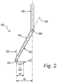
- Fig. 2 shows in detail the hook 48 illustrated in Fig. 1 , in a cross-section in a vertical plane, which is connected rigidly to the end of coupling body 46.
- the hook 48 has an outer side 50 and an inner side 52, and is divided into a bridge segment 54 and a hook segment 60.
- the bridge segment extends over a bridge length from a first end 56 that is connected to the coupling body 48, to a second end 58 that is connected to the hook segment 60.
- the hook segment extends over a hook length from the second end 58 to a free end of the hook 62.
- the bridge length in the horizontal direction is indicated as bL and the hook length in the horizontal direction as hL, wherein the value of bL is about 2.5 times greater than hL.
- An end part of the hook segment 60 that comprises the free end of the hook 62 is at an angle to the horizontal plane of about 15 degrees.
- the bridge segment 54 comprises an imaginary bridge line 64 that intersects the first end 56 and the second end 58 of the bridge segment, said bridge line 64 having a diagonal orientation relative to the horizontal plane, at an angle of about 60 degrees to the horizontal plane.
- the outer side 50 of the hook comprises rounded areas.
- Fig. 3 shows a top view of a part of the dismounting machine during the dismounting phase, in which the upper side 71 of a tyre 70 is mounted on a rim 72 whereas it is fixed on the upper side 10 of the carrying body by tightening a top nut 74 on the bolt 14.
- the guide arm 26 is positioned so that the guide head 28 lies tangentially with a front 68 against the outer edge 78 of the rim, whereas the inner edge 76 of the tyre lies on the guiding surface 29 of the guide head 28.
- a first, initial part of the inner edge of the tyre 70 has already been brought over the outer edge 78 of the rim, on which the hook 48 (for clarity in Fig. 3 , only shown with the coupling body 46 connected thereto) is brought into close contact behind the part shown of the inner edge 76, and is moved vertically upwards, wherein the inner edge 76 is moved over the outer edge 78 of the rim, and then the hook is held at a height of a few centimetres above the outer edge 78 of the rim.
- Fig. 4 shows a top view of a configuration of the guiding surface 29 of the guide head 28 that is connected to guide arm 26 and which can be applied in the situation shown in Fig. 3 .
- the guiding surface is formed in such a way that the front 68 has a concave shape, in order to seal well on the outer edge 78 of the rim.
- the opposite guiding surface has a bulge-shaped zone 80 and a recessed vertical sliding track 82.
- This sliding track 82 is suitable for sliding an outer side 50 of the hook 48 (see Fig. 2 ) over it during movement of the hook in a vertical direction when an inner edge of a tyre is being moved over an outer edge of the rim.
- the hook 48 can move the inner edge of a tyre very near the guide head 28 over the outer edge of the rim, whereas the hook 48 in the subsequent steps of dismounting moves together with the inner edge of the tyre, while the guide head 28 remains in the fixed working position.
Landscapes
- Engineering & Computer Science (AREA)
- Mechanical Engineering (AREA)
- Tyre Moulding (AREA)
- Tires In General (AREA)
Claims (15)
- Demontagemaschine (1) zum Demontieren eines Reifens von einer Felge, umfassend einen tragenden Grundrahmen (3), der bereitgestellt ist mit:- einem vertikalen Tragekörper (9) für eine Felge, wobei der Tragekörper mit dem Grundrahmen (3) verbunden ist, durch einen Motor relativ zu dem Grundrahmen um eine sich in einer vertikalen Richtung erstreckende Drehachse (11) drehbar ist und mit Befestigungsmitteln (14) zum Befestigen einer Felge in einer festen Position auf einer Oberseite (10) des Tragekörpers (9) bereitgestellt ist, sodass eine Hauptachse der so befestigten Felge sich in einer Richtung erstreckt, die mit der zentralen Drehachse (11) des Tragekörpers (9) übereinstimmt, sodass eine Drehung des Tragekörpers zu einer Drehung der befestigten Felge um die Hauptachse führt,- einer vertikalen Säule (20), die starr mit dem Grundrahmen (3) verbunden ist, der sich in einem Abstand vom Tragekörper (9) befindet, wobei die Säule (20) mit einem Führungsarm (26) und einem Hilfsarm (30) bereitgestellt ist, die sich von der Säule (20) in Richtung des Tragekörpers (9) erstrecken und die unabhängig voneinander beweglich mit der Säule (20) verbunden sind, sodass der Führungsarm (26) und der Hilfsarm (30) unabhängig voneinander in eine Arbeitsposition als separate Werkzeuge zum Demontieren eines Reifens von einer an dem Tragekörper (9) befestigten Felge gebracht werden können,wobei die Säule (20) mit einem motorgetriebenen Einstellmechanismus (22) zum Einstellen der Höhe des Führungsarms (26) an der Säule (20) bereitgestellt ist und der Führungsarm (26) an einem distalen Ende mit einem Führungskopf (28) mit einer Führungsfläche (29) bereitgestellt ist, die zum Führen einer Innenkante eines Reifens über eine Außenkante der Felge konzipiert ist, wenn sich der Führungsarm (26) in seiner Arbeitsposition zwischen der Außenkante der Felge und der Innenkante des Reifens befindet,dadurch gekennzeichnet, dass der Hilfsarm (30) schwenkbar mit einem proximalen Ende (32) mit der Säule (20) verbunden ist und ein distales Ende mit einem Hakenarm (40) bereitgestellt ist, von dem ein distales Ende mit einem Haken (48) verbunden ist, wobei der Haken (48) so konzipiert ist, hinter eine Innenkante eines Reifens zu greifen, wenn der Hilfsarm (30) in seine Arbeitsposition gebracht wird,wobei der Hakenarm (40) einen motorgetriebenen Hakenmechanismus (42) zum Bewegen des Hakens (48) in einer vertikalen Richtung umfasst, um eine Innenkante eines Reifens über eine Außenkante der Felge zu bewegen, wenn der Hilfsarm (30) in seine Arbeitsposition gebracht wird,und wobei der Hilfsarm (30) derart schwenkbar mit der Säule (20) verbunden ist, dass der Haken (48) einer kreisförmigen Bahn um die Drehachse (11) des Tragekörpers (9) folgen kann.
- Demontagemaschine (1) nach Anspruch 1, wobei der Hilfsarm (30) mindestens zwei miteinander verbundene Abschnitte (32,34) umfasst, wobei ein erster Abschnitt (32) mit einem proximalen Ende schwenkbar mit der Säule (20) verbunden ist und mit einem distalen Ende schwenkbar mit einem proximalen Ende eines zweiten Abschnitts (34) verbunden ist, wobei ein distales Ende des zweiten Abschnitts (34) das distale Ende des Hilfsarms (30) bildet.
- Demontagemaschine (1) nach einem der vorstehenden Ansprüche, wobei ein oder mehrere Drehgelenke (36,38) des Hilfsarms (30) derart dazu konfiguriert sind, dass das Drehgelenk (36,38) eine Schwenkung um eine vertikale Achse erreicht.
- Demontagemaschine (1) nach einem der vorstehenden Ansprüche, wobei der Hilfsarm (30) in einer Höhe schwenkbar mit der Säule (20) verbunden ist, die über der maximalen Höheneinstellung des Führungsarms (26) liegt.
- Demontagemaschine (1) nach einem der vorstehenden Ansprüche, wobei der motorgetriebene Hakenmechanismus (42) einen Arbeitsarm (44) umfasst, der mit einem distalen Ende mit dem Haken (48) verbunden ist, und wobei das distale Ende entlang einer vertikalen Achse bewegbar ist und vorzugsweise über eine Distanz von mindestens 15 bis 45 cm bewegbar ist.
- Demontagemaschine (1) nach einem der vorstehenden Ansprüche, wobei der Haken (48) relativ zu dem distalen Ende des Hilfsarms (30) drehbar montiert ist, sodass eine Drehung des Hakens (48) um eine vertikale Drehachse möglich ist.
- Demontagemaschine (1) nach einem der vorstehenden Ansprüche, wobei der Hakenarm (40) einen Kupplungskörper (46) umfasst, der an einem ersten Ende mit dem Haken (48) verbunden ist und mit einem zweiten Ende mit dem Hakenmechanismus (42) verbunden ist.
- Demontagemaschine (1) nach einem der vorstehenden Ansprüche, wobei der Haken (48) über eine Kupplungsverbindung (46) lösbar mit dem Hakenmechanismus (42) verbunden ist.
- Demontagemaschine (1) nach einem der vorstehenden Ansprüche, wobei die Demontagemaschine (1) einen pneumatischen Motor als Energiequelle für den motorischen Antrieb des Hakenmechanismus (42) umfasst.
- Demontagemaschine (1) nach einem der vorhergehenden Ansprüche, wobei der Haken (48) als ein gekrümmter Körper konfiguriert ist, der ein Brückensegment (54) und ein Hakensegment (60) umfasst, wobei das Brückensegment (54) und das Hakensegment (60) einander gegenüberliegend in einer gemeinsamen vertikalen Ebene montiert sind, und wobei das Brückensegment (54) ein oberes Segment des Hakens (48) ist und das Hakensegment (60) ein unteres Segment des Hakens (48) ist, das zum Greifen hinter einer Innenkante eines Reifens angeordnet ist,wobei sich das Brückensegment (54) über eine Brückenlänge (bL) von einem mit dem Hakenarm (40) verbundenen ersten Ende (56) zu einem mit dem Hakensegment (60) verbundenen zweiten Ende (58) erstreckt undsich das Hakensegment (60) über eine Hakenlänge (hL) von einem mit dem Brückensegment (54) verbundenen ersten Ende (58) zu einem mit einem freien Ende des Hakens übereinstimmenden zweiten Ende (62) erstreckt,wobei die Brückenlänge (bL) in horizontaler Richtung größer als die Hakenlänge (hL) in horizontaler Richtung ist, insbesondere 2- bis 6-mal größer.
- Demontagemaschine (1) nach Anspruch 10, wobei ein Endteil des Hakensegments (60), welches das freie Ende des Hakens (62) umfasst, in einem Winkel zu der horizontalen Ebene in dem Bereich von 0 bis 30 Grad steht und sich vorzugsweise zu dem freien Ende (62) hin verjüngt.
- Demontagemaschine (1) nach Anspruch 10 oder 11, wobei das Brückensegment (54) eine imaginäre Brückenlinie (64) definiert, die das erste Ende (56) und das zweite Ende (58) des Brückensegments (54) schneidet, wobei die Brückenlinie (64) eine diagonale Ausrichtung relativ zu der horizontalen Ebene aufweist und vorzugsweise in einem Winkel von 30 bis 80 Grad zu der horizontalen Ebene steht.
- Demontagemaschine (1) nach einem der vorstehenden Ansprüche, wobei der Haken (48) eine Außenseite (50) mit einer Außenfläche aufweist, die abgerundete Bereiche umfasst.
- Demontagemaschine (1) nach einem der vorstehenden Ansprüche, wobei die Führungsfläche (29) mit einer vertieften vertikalen Gleitbahn (82) bereitgestellt ist, über die eine Außenseite (50) des Hakens (48) mit einer Gleitbewegung bewegt werden kann, insbesondere während der Bewegung des Hakens (48) in einer vertikalen Richtung, wenn eine Innenkante eines Reifens über eine Außenkante der Felge bewegt wird.
- Verfahren zum Demontieren eines Reifens von einer Felge mit einer Demontagemaschine (1) nach einem der vorstehenden Ansprüche, wobei das Verfahren die folgenden aufeinanderfolgenden Schritte umfasst:i) Anordnen des Hilfsarms (30) und des Führungsarms (26) in ihren jeweiligen Arbeitspositionen relativ zu dem Tragekörper (9), auf dem eine Felge mit montiertem Reifen befestigt ist, wobei der Führungskopf (28) angrenzend an die Außenkante der Felge positioniert ist und der Haken (48) des Hakenarms (40) sich in der Nähe des Führungskopfes (28) befindet und in engem Kontakt hinter einem ersten Teil der Innenkante des Reifens platziert ist;ii) Bewegen des Hakens (48) vertikal nach oben, sodass der erste Teil der Innenkante des Reifens über die Außenkante der Felge und gleichzeitig über die Führungsfläche (29) des Führungskopfes (28) bewegt wird;iii) Bringen des Hakens (48) auf eine feste Höhe, wobei diese über der Außenkante der Felge liegt, während er in engem Kontakt mit der Innenkante des Reifens bleibt;iv) dann Drehen des Tragekörpers (9), sodass die feststehende Felge und der Reifen gedreht werden, während der Haken (48) in engem Kontakt mit dem ersten Teil der Innenkante des Reifens während der Drehung der Felge bleibt, sodass sich der Haken (48) entlang der kreisförmigen Bahn bewegt, der die Innenkante des Reifens während der Drehung (R) der Felge folgt, und wobei gleichzeitig der Führungskopf (28) in seiner Arbeitsposition gehalten wird, sodass ein passierender Teil der Innenkante des Reifens durch die Führungsfläche (29) über die Außenkante der Felge geführt wird.
Applications Claiming Priority (2)
| Application Number | Priority Date | Filing Date | Title |
|---|---|---|---|
| NL2026774A NL2026774B1 (nl) | 2020-10-27 | 2020-10-27 | Demontagemachine voor het demonteren van een band van een velg, en werkwijze voor het demonteren van een band van een velg. |
| PCT/NL2021/050647 WO2022093015A1 (en) | 2020-10-27 | 2021-10-26 | Dismounting machine for dismounting a tyre from a rim, and method for dismounting a tyre from a rim |
Publications (3)
| Publication Number | Publication Date |
|---|---|
| EP4237263A1 EP4237263A1 (de) | 2023-09-06 |
| EP4237263B1 true EP4237263B1 (de) | 2025-03-05 |
| EP4237263C0 EP4237263C0 (de) | 2025-03-05 |
Family
ID=75340196
Family Applications (1)
| Application Number | Title | Priority Date | Filing Date |
|---|---|---|---|
| EP21798469.9A Active EP4237263B1 (de) | 2020-10-27 | 2021-10-26 | Reifendemontagemaschine und methode zur demontage eines reifens von einer felge |
Country Status (4)
| Country | Link |
|---|---|
| US (1) | US12466220B2 (de) |
| EP (1) | EP4237263B1 (de) |
| NL (1) | NL2026774B1 (de) |
| WO (1) | WO2022093015A1 (de) |
Citations (1)
| Publication number | Priority date | Publication date | Assignee | Title |
|---|---|---|---|---|
| US10000101B2 (en) * | 2014-09-15 | 2018-06-19 | Nexion S.P.A. | Machine for fitting and removing a tyre and method for operating the machine |
Family Cites Families (20)
| Publication number | Priority date | Publication date | Assignee | Title |
|---|---|---|---|---|
| JP2009227006A (ja) * | 2008-03-19 | 2009-10-08 | Onodani Kiko Kk | タイヤ着脱装置のタイヤビード案内装置 |
| ES2356039T3 (es) * | 2008-04-17 | 2011-04-04 | Snap-On Equipment Srl A Unico Socio | Procedimiento y aparato para montar y desmontar un neumático de vehículo a motor. |
| IT1393290B1 (it) * | 2008-09-08 | 2012-04-20 | M&B Engineering S R L | Dispositivo per il montaggio e lo smontaggio di pneumatici |
| IT1392089B1 (it) * | 2008-10-13 | 2012-02-09 | Giuliano S P A Ora Giuliano Group S P A | Testa operativa per lo smontaggio ed il montaggio di pneumatici di ruote per veicoli |
| IT1402585B1 (it) * | 2010-10-22 | 2013-09-13 | Maioli | Macchina smontagomme. |
| IT1402588B1 (it) * | 2010-11-02 | 2013-09-13 | Teco Srl | Dispositivo di orientamento di un attrezzo di lavoro in una macchina smontagomme |
| US8973640B1 (en) * | 2010-12-07 | 2015-03-10 | Hunter Engineering Company | Demount tool assembly and methods for automated tire changer machine |
| ITMO20110119A1 (it) * | 2011-05-20 | 2012-11-21 | Giuliano Group Spa | Macchina per il montaggio e lo smontaggio di pneumatici di ruote per veicoli |
| ITMO20110120A1 (it) * | 2011-05-23 | 2012-11-24 | Teco Srl | Un apparato di posizionamento angolare di un braccio operativo di una macchina smontagomme |
| ITMO20120009A1 (it) * | 2012-01-16 | 2013-07-17 | Gino Ferrari | Dispositivo estrattore per macchine smontagomme |
| CN202727895U (zh) * | 2012-05-17 | 2013-02-13 | 高庆军 | 一种自动轮胎拆装机 |
| JP2014162271A (ja) * | 2013-02-22 | 2014-09-08 | Altlife Co Ltd | タイヤ固定機構及びタイヤチェンジャ |
| CN105050837B (zh) * | 2013-02-28 | 2017-12-12 | 中央精机株式会社 | 轮胎组装装置 |
| ES2616537T3 (es) * | 2014-07-03 | 2017-06-13 | Corghi S.P.A. | Máquina y método para montar y desmontar un neumático |
| EP2987661B1 (de) * | 2014-07-28 | 2019-10-23 | Butler Engineering & Marketing S.p.A. | Vorrichtung zur montage- und demontage eines bereiften rades sowie maschine mit solch einer vorrichtung |
| ITUB20152448A1 (it) * | 2015-07-10 | 2017-01-10 | Franco Maioli | Dispositivo smonta gomme |
| IT201600091443A1 (it) * | 2016-09-09 | 2018-03-09 | Devel S R L | Macchina per il montaggio e lo smontaggio di pneumatici di ruote di veicoli |
| IT201800010722A1 (it) * | 2018-11-30 | 2020-05-30 | Nexion Spa | Apparato smontagomme |
| NL2022247B1 (nl) * | 2018-12-19 | 2020-07-03 | Techno Group Benelux B V | Bandmontage-eenheid, en bandenservicesysteem omvattende een bandmontage-eenheid |
| CN112297724B (zh) * | 2020-11-24 | 2021-08-10 | 中意泰达(营口)汽车保修设备有限公司 | 新型拆装轮胎装置 |
-
2020
- 2020-10-27 NL NL2026774A patent/NL2026774B1/nl active
-
2021
- 2021-10-26 EP EP21798469.9A patent/EP4237263B1/de active Active
- 2021-10-26 WO PCT/NL2021/050647 patent/WO2022093015A1/en not_active Ceased
- 2021-10-26 US US18/033,877 patent/US12466220B2/en active Active
Patent Citations (1)
| Publication number | Priority date | Publication date | Assignee | Title |
|---|---|---|---|---|
| US10000101B2 (en) * | 2014-09-15 | 2018-06-19 | Nexion S.P.A. | Machine for fitting and removing a tyre and method for operating the machine |
Also Published As
| Publication number | Publication date |
|---|---|
| WO2022093015A1 (en) | 2022-05-05 |
| US20230398819A1 (en) | 2023-12-14 |
| US12466220B2 (en) | 2025-11-11 |
| EP4237263C0 (de) | 2025-03-05 |
| EP4237263A1 (de) | 2023-09-06 |
| NL2026774B1 (nl) | 2022-06-21 |
Similar Documents
| Publication | Publication Date | Title |
|---|---|---|
| US7014413B2 (en) | Door attaching apparatus | |
| US7591295B2 (en) | Bead breaking unit for tire changing machines | |
| US5725422A (en) | Auto body buffing machine with handle angularly adjustable to different fixed positions | |
| US5137235A (en) | Inverted angle drill | |
| EP1593533A2 (de) | Automatische Radmontier- und Demontiervorrichtung | |
| EP1897709B1 (de) | Maschine zum Anbringen und Abnehmen von Fahrzeugreifen | |
| EP2062752B1 (de) | Maschine zum Anbringen und Abnehmen von Reifen für Fahrzeuge | |
| CN107953733B (zh) | 轮胎更换机 | |
| US4331278A (en) | Pipe welding apparatus | |
| AU727672B2 (en) | Portable cutting apparatus | |
| EP1201467A2 (de) | Reifendemontiervorrichtung | |
| EP4237263B1 (de) | Reifendemontagemaschine und methode zur demontage eines reifens von einer felge | |
| EP3659832B1 (de) | Reifenwechselgerät | |
| US5060708A (en) | Tire mounting and dismounting apparatus | |
| CN221538412U (zh) | 一种异形梁焊接装置 | |
| CN113020396A (zh) | 一种自动切边机 | |
| CN119897625A (zh) | 一种法兰球阀楼栋调压箱的箱体焊接装置 | |
| CN219378554U (zh) | 一种钢管折弯机 | |
| CN106087285B (zh) | 一种靠边器 | |
| CN115041720B (zh) | 一种变径孔加工装置 | |
| CN113510775B (zh) | 一种橡胶实心胎表面斜纹开槽设备 | |
| US6688150B1 (en) | Roll grooving apparatus | |
| CN112605600B (zh) | 适应不同板面角度的螺旋叶片的夹装需求的夹装设备 | |
| JPH07115457B2 (ja) | 版胴上で版板を調節するための装置 | |
| CN220336364U (zh) | 一种墙面刷漆设备 |
Legal Events
| Date | Code | Title | Description |
|---|---|---|---|
| STAA | Information on the status of an ep patent application or granted ep patent |
Free format text: STATUS: UNKNOWN |
|
| STAA | Information on the status of an ep patent application or granted ep patent |
Free format text: STATUS: THE INTERNATIONAL PUBLICATION HAS BEEN MADE |
|
| PUAI | Public reference made under article 153(3) epc to a published international application that has entered the european phase |
Free format text: ORIGINAL CODE: 0009012 |
|
| STAA | Information on the status of an ep patent application or granted ep patent |
Free format text: STATUS: REQUEST FOR EXAMINATION WAS MADE |
|
| 17P | Request for examination filed |
Effective date: 20230530 |
|
| AK | Designated contracting states |
Kind code of ref document: A1 Designated state(s): AL AT BE BG CH CY CZ DE DK EE ES FI FR GB GR HR HU IE IS IT LI LT LU LV MC MK MT NL NO PL PT RO RS SE SI SK SM TR |
|
| DAV | Request for validation of the european patent (deleted) | ||
| DAX | Request for extension of the european patent (deleted) | ||
| STAA | Information on the status of an ep patent application or granted ep patent |
Free format text: STATUS: EXAMINATION IS IN PROGRESS |
|
| 17Q | First examination report despatched |
Effective date: 20240522 |
|
| GRAP | Despatch of communication of intention to grant a patent |
Free format text: ORIGINAL CODE: EPIDOSNIGR1 |
|
| STAA | Information on the status of an ep patent application or granted ep patent |
Free format text: STATUS: GRANT OF PATENT IS INTENDED |
|
| INTG | Intention to grant announced |
Effective date: 20240923 |
|
| GRAS | Grant fee paid |
Free format text: ORIGINAL CODE: EPIDOSNIGR3 |
|
| GRAA | (expected) grant |
Free format text: ORIGINAL CODE: 0009210 |
|
| STAA | Information on the status of an ep patent application or granted ep patent |
Free format text: STATUS: THE PATENT HAS BEEN GRANTED |
|
| AK | Designated contracting states |
Kind code of ref document: B1 Designated state(s): AL AT BE BG CH CY CZ DE DK EE ES FI FR GB GR HR HU IE IS IT LI LT LU LV MC MK MT NL NO PL PT RO RS SE SI SK SM TR |
|
| REG | Reference to a national code |
Ref country code: GB Ref legal event code: FG4D |
|
| REG | Reference to a national code |
Ref country code: CH Ref legal event code: EP |
|
| REG | Reference to a national code |
Ref country code: IE Ref legal event code: FG4D |
|
| REG | Reference to a national code |
Ref country code: DE Ref legal event code: R096 Ref document number: 602021027246 Country of ref document: DE |
|
| U01 | Request for unitary effect filed |
Effective date: 20250404 |
|
| U07 | Unitary effect registered |
Designated state(s): AT BE BG DE DK EE FI FR IT LT LU LV MT NL PT RO SE SI Effective date: 20250509 |
|
| PG25 | Lapsed in a contracting state [announced via postgrant information from national office to epo] |
Ref country code: RS Free format text: LAPSE BECAUSE OF FAILURE TO SUBMIT A TRANSLATION OF THE DESCRIPTION OR TO PAY THE FEE WITHIN THE PRESCRIBED TIME-LIMIT Effective date: 20250605 |
|
| PG25 | Lapsed in a contracting state [announced via postgrant information from national office to epo] |
Ref country code: ES Free format text: LAPSE BECAUSE OF FAILURE TO SUBMIT A TRANSLATION OF THE DESCRIPTION OR TO PAY THE FEE WITHIN THE PRESCRIBED TIME-LIMIT Effective date: 20250305 |
|
| PG25 | Lapsed in a contracting state [announced via postgrant information from national office to epo] |
Ref country code: NO Free format text: LAPSE BECAUSE OF FAILURE TO SUBMIT A TRANSLATION OF THE DESCRIPTION OR TO PAY THE FEE WITHIN THE PRESCRIBED TIME-LIMIT Effective date: 20250605 |
|
| PG25 | Lapsed in a contracting state [announced via postgrant information from national office to epo] |
Ref country code: HR Free format text: LAPSE BECAUSE OF FAILURE TO SUBMIT A TRANSLATION OF THE DESCRIPTION OR TO PAY THE FEE WITHIN THE PRESCRIBED TIME-LIMIT Effective date: 20250305 |
|
| PG25 | Lapsed in a contracting state [announced via postgrant information from national office to epo] |
Ref country code: GR Free format text: LAPSE BECAUSE OF FAILURE TO SUBMIT A TRANSLATION OF THE DESCRIPTION OR TO PAY THE FEE WITHIN THE PRESCRIBED TIME-LIMIT Effective date: 20250606 |
|
| PG25 | Lapsed in a contracting state [announced via postgrant information from national office to epo] |
Ref country code: SM Free format text: LAPSE BECAUSE OF FAILURE TO SUBMIT A TRANSLATION OF THE DESCRIPTION OR TO PAY THE FEE WITHIN THE PRESCRIBED TIME-LIMIT Effective date: 20250305 |
|
| PG25 | Lapsed in a contracting state [announced via postgrant information from national office to epo] |
Ref country code: PL Free format text: LAPSE BECAUSE OF FAILURE TO SUBMIT A TRANSLATION OF THE DESCRIPTION OR TO PAY THE FEE WITHIN THE PRESCRIBED TIME-LIMIT Effective date: 20250305 |
|
| PG25 | Lapsed in a contracting state [announced via postgrant information from national office to epo] |
Ref country code: CZ Free format text: LAPSE BECAUSE OF FAILURE TO SUBMIT A TRANSLATION OF THE DESCRIPTION OR TO PAY THE FEE WITHIN THE PRESCRIBED TIME-LIMIT Effective date: 20250305 |
|
| PG25 | Lapsed in a contracting state [announced via postgrant information from national office to epo] |
Ref country code: SK Free format text: LAPSE BECAUSE OF FAILURE TO SUBMIT A TRANSLATION OF THE DESCRIPTION OR TO PAY THE FEE WITHIN THE PRESCRIBED TIME-LIMIT Effective date: 20250305 |
|
| PG25 | Lapsed in a contracting state [announced via postgrant information from national office to epo] |
Ref country code: IS Free format text: LAPSE BECAUSE OF FAILURE TO SUBMIT A TRANSLATION OF THE DESCRIPTION OR TO PAY THE FEE WITHIN THE PRESCRIBED TIME-LIMIT Effective date: 20250705 |
|
| U20 | Renewal fee for the european patent with unitary effect paid |
Year of fee payment: 5 Effective date: 20251027 |
|
| PLBE | No opposition filed within time limit |
Free format text: ORIGINAL CODE: 0009261 |
|
| STAA | Information on the status of an ep patent application or granted ep patent |
Free format text: STATUS: NO OPPOSITION FILED WITHIN TIME LIMIT |
|
| REG | Reference to a national code |
Ref country code: CH Ref legal event code: L10 Free format text: ST27 STATUS EVENT CODE: U-0-0-L10-L00 (AS PROVIDED BY THE NATIONAL OFFICE) Effective date: 20260114 |
|
| 26N | No opposition filed |
Effective date: 20251208 |