EP4236025B1 - Drahtloser energieempfänger - Google Patents
Drahtloser energieempfänger Download PDFInfo
- Publication number
- EP4236025B1 EP4236025B1 EP23178394.5A EP23178394A EP4236025B1 EP 4236025 B1 EP4236025 B1 EP 4236025B1 EP 23178394 A EP23178394 A EP 23178394A EP 4236025 B1 EP4236025 B1 EP 4236025B1
- Authority
- EP
- European Patent Office
- Prior art keywords
- foreign object
- wireless power
- quality factor
- value
- object detection
- Prior art date
- Legal status (The legal status is an assumption and is not a legal conclusion. Google has not performed a legal analysis and makes no representation as to the accuracy of the status listed.)
- Active
Links
Images


Classifications
-
- H—ELECTRICITY
- H02—GENERATION; CONVERSION OR DISTRIBUTION OF ELECTRIC POWER
- H02J—CIRCUIT ARRANGEMENTS OR SYSTEMS FOR SUPPLYING OR DISTRIBUTING ELECTRIC POWER; SYSTEMS FOR STORING ELECTRIC ENERGY
- H02J50/00—Circuit arrangements or systems for wireless supply or distribution of electric power
- H02J50/60—Circuit arrangements or systems for wireless supply or distribution of electric power responsive to the presence of foreign objects, e.g. detection of living beings
-
- H—ELECTRICITY
- H02—GENERATION; CONVERSION OR DISTRIBUTION OF ELECTRIC POWER
- H02J—CIRCUIT ARRANGEMENTS OR SYSTEMS FOR SUPPLYING OR DISTRIBUTING ELECTRIC POWER; SYSTEMS FOR STORING ELECTRIC ENERGY
- H02J50/00—Circuit arrangements or systems for wireless supply or distribution of electric power
- H02J50/10—Circuit arrangements or systems for wireless supply or distribution of electric power using inductive coupling
- H02J50/12—Circuit arrangements or systems for wireless supply or distribution of electric power using inductive coupling of the resonant type
-
- H—ELECTRICITY
- H02—GENERATION; CONVERSION OR DISTRIBUTION OF ELECTRIC POWER
- H02J—CIRCUIT ARRANGEMENTS OR SYSTEMS FOR SUPPLYING OR DISTRIBUTING ELECTRIC POWER; SYSTEMS FOR STORING ELECTRIC ENERGY
- H02J50/00—Circuit arrangements or systems for wireless supply or distribution of electric power
- H02J50/20—Circuit arrangements or systems for wireless supply or distribution of electric power using microwaves or radio frequency waves
-
- H—ELECTRICITY
- H02—GENERATION; CONVERSION OR DISTRIBUTION OF ELECTRIC POWER
- H02J—CIRCUIT ARRANGEMENTS OR SYSTEMS FOR SUPPLYING OR DISTRIBUTING ELECTRIC POWER; SYSTEMS FOR STORING ELECTRIC ENERGY
- H02J50/00—Circuit arrangements or systems for wireless supply or distribution of electric power
- H02J50/40—Circuit arrangements or systems for wireless supply or distribution of electric power using two or more transmitting or receiving devices
- H02J50/402—Circuit arrangements or systems for wireless supply or distribution of electric power using two or more transmitting or receiving devices the two or more transmitting or the two or more receiving devices being integrated in the same unit, e.g. power mats with several coils or antennas with several sub-antennas
-
- H—ELECTRICITY
- H02—GENERATION; CONVERSION OR DISTRIBUTION OF ELECTRIC POWER
- H02J—CIRCUIT ARRANGEMENTS OR SYSTEMS FOR SUPPLYING OR DISTRIBUTING ELECTRIC POWER; SYSTEMS FOR STORING ELECTRIC ENERGY
- H02J50/00—Circuit arrangements or systems for wireless supply or distribution of electric power
- H02J50/80—Circuit arrangements or systems for wireless supply or distribution of electric power involving the exchange of data, concerning supply or distribution of electric power, between transmitting devices and receiving devices
-
- H—ELECTRICITY
- H02—GENERATION; CONVERSION OR DISTRIBUTION OF ELECTRIC POWER
- H02J—CIRCUIT ARRANGEMENTS OR SYSTEMS FOR SUPPLYING OR DISTRIBUTING ELECTRIC POWER; SYSTEMS FOR STORING ELECTRIC ENERGY
- H02J50/00—Circuit arrangements or systems for wireless supply or distribution of electric power
- H02J50/90—Circuit arrangements or systems for wireless supply or distribution of electric power involving detection or optimisation of position, e.g. alignment
-
- H—ELECTRICITY
- H02—GENERATION; CONVERSION OR DISTRIBUTION OF ELECTRIC POWER
- H02J—CIRCUIT ARRANGEMENTS OR SYSTEMS FOR SUPPLYING OR DISTRIBUTING ELECTRIC POWER; SYSTEMS FOR STORING ELECTRIC ENERGY
- H02J7/00—Circuit arrangements for charging or depolarising batteries or for supplying loads from batteries
- H02J7/00032—Circuit arrangements for charging or depolarising batteries or for supplying loads from batteries characterised by data exchange
- H02J7/00036—Charger exchanging data with battery
-
- H—ELECTRICITY
- H02—GENERATION; CONVERSION OR DISTRIBUTION OF ELECTRIC POWER
- H02J—CIRCUIT ARRANGEMENTS OR SYSTEMS FOR SUPPLYING OR DISTRIBUTING ELECTRIC POWER; SYSTEMS FOR STORING ELECTRIC ENERGY
- H02J7/00—Circuit arrangements for charging or depolarising batteries or for supplying loads from batteries
- H02J7/02—Circuit arrangements for charging or depolarising batteries or for supplying loads from batteries for charging batteries from AC mains by converters
-
- H—ELECTRICITY
- H04—ELECTRIC COMMUNICATION TECHNIQUE
- H04B—TRANSMISSION
- H04B17/00—Monitoring; Testing
- H04B17/30—Monitoring; Testing of propagation channels
- H04B17/309—Measuring or estimating channel quality parameters
- H04B17/318—Received signal strength
-
- H—ELECTRICITY
- H04—ELECTRIC COMMUNICATION TECHNIQUE
- H04L—TRANSMISSION OF DIGITAL INFORMATION, e.g. TELEGRAPHIC COMMUNICATION
- H04L1/00—Arrangements for detecting or preventing errors in the information received
- H04L1/0078—Avoidance of errors by organising the transmitted data in a format specifically designed to deal with errors, e.g. location
- H04L1/0079—Formats for control data
-
- H—ELECTRICITY
- H04—ELECTRIC COMMUNICATION TECHNIQUE
- H04L—TRANSMISSION OF DIGITAL INFORMATION, e.g. TELEGRAPHIC COMMUNICATION
- H04L5/00—Arrangements affording multiple use of the transmission path
- H04L5/003—Arrangements for allocating sub-channels of the transmission path
- H04L5/0053—Allocation of signalling, i.e. of overhead other than pilot signals
- H04L5/0055—Physical resource allocation for ACK/NACK
-
- H—ELECTRICITY
- H04—ELECTRIC COMMUNICATION TECHNIQUE
- H04L—TRANSMISSION OF DIGITAL INFORMATION, e.g. TELEGRAPHIC COMMUNICATION
- H04L69/00—Network arrangements, protocols or services independent of the application payload and not provided for in the other groups of this subclass
- H04L69/24—Negotiation of communication capabilities
-
- Y—GENERAL TAGGING OF NEW TECHNOLOGICAL DEVELOPMENTS; GENERAL TAGGING OF CROSS-SECTIONAL TECHNOLOGIES SPANNING OVER SEVERAL SECTIONS OF THE IPC; TECHNICAL SUBJECTS COVERED BY FORMER USPC CROSS-REFERENCE ART COLLECTIONS [XRACs] AND DIGESTS
- Y02—TECHNOLOGIES OR APPLICATIONS FOR MITIGATION OR ADAPTATION AGAINST CLIMATE CHANGE
- Y02T—CLIMATE CHANGE MITIGATION TECHNOLOGIES RELATED TO TRANSPORTATION
- Y02T10/00—Road transport of goods or passengers
- Y02T10/60—Other road transportation technologies with climate change mitigation effect
- Y02T10/70—Energy storage systems for electromobility, e.g. batteries
-
- Y—GENERAL TAGGING OF NEW TECHNOLOGICAL DEVELOPMENTS; GENERAL TAGGING OF CROSS-SECTIONAL TECHNOLOGIES SPANNING OVER SEVERAL SECTIONS OF THE IPC; TECHNICAL SUBJECTS COVERED BY FORMER USPC CROSS-REFERENCE ART COLLECTIONS [XRACs] AND DIGESTS
- Y02—TECHNOLOGIES OR APPLICATIONS FOR MITIGATION OR ADAPTATION AGAINST CLIMATE CHANGE
- Y02T—CLIMATE CHANGE MITIGATION TECHNOLOGIES RELATED TO TRANSPORTATION
- Y02T10/00—Road transport of goods or passengers
- Y02T10/60—Other road transportation technologies with climate change mitigation effect
- Y02T10/7072—Electromobility specific charging systems or methods for batteries, ultracapacitors, supercapacitors or double-layer capacitors
-
- Y—GENERAL TAGGING OF NEW TECHNOLOGICAL DEVELOPMENTS; GENERAL TAGGING OF CROSS-SECTIONAL TECHNOLOGIES SPANNING OVER SEVERAL SECTIONS OF THE IPC; TECHNICAL SUBJECTS COVERED BY FORMER USPC CROSS-REFERENCE ART COLLECTIONS [XRACs] AND DIGESTS
- Y02—TECHNOLOGIES OR APPLICATIONS FOR MITIGATION OR ADAPTATION AGAINST CLIMATE CHANGE
- Y02T—CLIMATE CHANGE MITIGATION TECHNOLOGIES RELATED TO TRANSPORTATION
- Y02T90/00—Enabling technologies or technologies with a potential or indirect contribution to GHG emissions mitigation
- Y02T90/10—Technologies relating to charging of electric vehicles
- Y02T90/14—Plug-in electric vehicles
Definitions
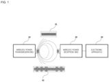
- Embodiments relate to wireless power transmission technology and, more particularly, a wireless power receiver.
- EP 2 552 030 A2 discloses a wireless power receiver according to the preamble of claim 1.
- the Wireless Power Consortium published a "System Description Wireless Power Transfer, Volume I: Lew Power, Part 1: Interface Definition, Version 1.1.2 ", which discloses mode fields.
- KR 2015 0059069 A discloses a wireless power transmitter which can detect not only existence of an external metal material, but also energy consumed by the external metal material. The wireless power detects power lost by the external metal material, and outputs information presenting the detected power.
- WO 2016/024869 A1 discloses a system for inductive power transfer that selectively transmits power in a plurality of modes based on characteristics of a power receiver and determine which transmitter coils to drive based on received signal strength information.
- a wireless energy transfer method may be roughly divided into a magnetic induction method, an electromagnetic resonance method and a radio frequency (RF) transmission method of a short-wavelength radio frequency.
- RF radio frequency
- the magnetic induction method uses a phenomenon that, when two coils are located adjacent to each other and then current is applied to one coil, a magnetic flux is generated to cause an electromotive force in the other coil, and is rapidly being commercialized in small devices such as mobile phones.
- the magnetic induction method may transfer power of up to several hundreds of kilowatts (kW) and has high efficiency. However, since a maximum transmission distance is 1 centimeter (cm) or less, a device to be charged should be located adjacent to a charger or the floor.
- the electromagnetic resonance method uses an electric field or a magnetic field instead of using electromagnetic waves or current.
- the electromagnetic resonance method is rarely influenced by electromagnetic waves and thus is advantageously safe for other electronic devices or human bodies. In contrast, this method may be used in a limited distance and space and energy transmission efficiency is somewhat low.
- the short-wavelength wireless power transmission method (briefly, referred to as the RF transmission method) takes advantage of the fact that energy may be directly transmitted and received in the form of a radio wave.
- This technology is a RF wireless power transmission method using a rectenna.
- the rectenna is a combination of an antenna and a rectifier and means an element for directly converting RF power into DC power. That is, the RF method is technology of converting AC radio waves into DC.
- Wireless power transmission technology may be used not only in mobile related industries but also in various industries such as IT, railroad and home appliance.
- a conductor which is not a wireless power receiver, that is, a foreign object (FO) is present in a wireless charging area
- an electromagnetic signal received from a wireless power transmitter may be induced in the FO, thereby increasing in temperature.
- the FO may include coins, clips, pins, and ballpoint pens.
- wireless charging efficiency may be significantly lowered, and the temperatures of the wireless power receiver and the wireless power transmitter may increase due to increase in ambient temperature of the FO. If the FO located in the charging area is not removed, power waste may occur and the wireless power transmitter and the wireless power receiver may be damaged due to overheating.
- Embodiments provide a wireless power receiver.
- the wireless power receiver is used within a foreign object detection method capable of more accurately detecting a foreign object, by dynamically calibrating a measured quality factor value upon detecting the foreign object according to shift of a current peak frequency from a reference peak frequency.
- the foreign object detection method is capable of more accurately detecting a foreign object, by calculating a quality factor slope based on output voltage levels measured at a current peak frequency and a start frequency within an operating frequency band and comparing the quality factor slope with a predetermined quality factor slope threshold value.
- the foreign object detection method is capable of more accurately detecting a foreign object, by calculating a quality factor slope based on quality factor values measured at a current peak frequency and a start frequency within an operating frequency band and comparing the quality factor slope with a predetermined quality factor slope threshold value.
- the foreign object detection method is capable of improving foreign object detection capability, by adaptively applying a foreign object detection method based on a quality factor and a foreign object detection method based on a peak frequency.
- Embodiments provide a wireless power receiver.
- the wireless power receiver is capable of more accurately detecting a foreign object.
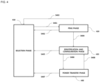
- FIG. 4 is a state transition diagram explaining a wireless power transfer procedure defined in the WPC standard.
- power transfer from the transmitter to the receiver is broadly divided into a selection phase 410, a ping phase 420, an identification and configuration phase 430, and a power transfer phase 440.
- the selection phase 410 transitions when power transfer starts or when a specific error or a specific event is sensed while power transfer is maintained.
- the specific error and the specific event will become apparent from the following description.
- the transmitter monitors whether an object is present on a charging interface surface. Upon detecting that the object is placed on the charging interface surface, the transmitter transitions to the ping phase 420 (S401).
- the transmitter transmits an analog ping signal having a very short pulse and detects whether an object is present in an active area, that is, a chargeable area, of the charging interface surface based on change in current of the transmission coil.
- the transmitter When the object is detected in the ping phase 420, the transmitter activates, that is, boots, the receiver and transmits a digital ping for identifying whether the object is a receiver.
- a response signal for example, a signal strength indicator
- the transmitter may transition to the selection phase 410 again (S402).
- the transmitter may transition to the selection phase 410 (S403).
- the transmitter may identify the receiver and transition to the identification and configuration phase 430 for identifying the receiver and collecting the configuration and status information of the receiver (S404).
- the transmitter transitions to the selection phase 410 (S405).
- the transmitter transitions to the power transfer phase 440 for transferring wireless power (S406).
- the transmitter transitions to the selection phase 410 (S407).
- the transmitter transitions to the identification and configuration phase 430 (S408).
- the power transfer contract is configured based on the transmitter and receiver status information and characteristic information.
- the transmitter status information may include information on the maximum amount of transmittable power, information on the maximum number of receivable receivers, etc. and the receiver status information may include information on required power.
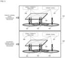
- FIGs. 5a and 5b are state transition diagrams explaining a wireless power transfer procedure.
- power transfer from the transmitter to the receiver is broadly divided into a selection phase 510, a ping phase 520, an identification and configuration phase 530, a negotiation phase 540, a calibration phase 550, a power transfer phase 560 and a renegotiation phase 570.
- the selection phase 510 may transition when power transfer starts or when a specific error or a specific event is sensed while power transfer is maintained (for example, including reference numerals S502, S504, S508, S510 and S512). The specific error and the specific event will become apparent from the following description.
- the transmitter may monitor whether an object is present on an interface surface. Upon detecting that the object is present on the interface surface, the transmitter may transition to the ping step 520. In the selection phase 510, the transmitter may transmit an analog ping signal having a very short pulse and detect whether an object is present in an active area of the interface surface based on change in current of a transmission coil or a primary coil.
- the wireless power transmitter measures the quality factor of a wireless power resonant circuit (e.g., a power transfer coil and/or a resonant capacitor).
- a wireless power resonant circuit e.g., a power transfer coil and/or a resonant capacitor.
- the quality factor is measured in order to determine whether the wireless power receiver is placed in the charging area along with a foreign object.
- the coil provided in the wireless power transmitter has an inductance and/or a series resistance component in the coil which may decrease due to environmental change, thereby decreasing the quality factor value.
- the wireless power transmitter receives, from the wireless power receiver, a reference quality factor value previously measured in a state in which a foreign object is not placed in the charging area.
- the reference quality factor value received in the negotiation phase 540 is compared with the measured quality factor value, thereby determining whether the foreign object is present.
- a wireless power receiver having a low reference quality factor for example, a specific wireless receiver may have a low reference quality factor value according to the type, usage and characteristics of the wireless power receiver
- a difference between the quality factor value measured when the foreign object is present and the reference quality factor is small, it is difficult to determine whether a foreign object is present. Accordingly, it is necessary to further consider other determination elements or to determine whether a foreign object is present using other methods.
- the quality factor value within a specific frequency region is measured in order to determine whether the wireless power receiver is placed in the charging area along with the foreign object.
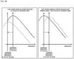
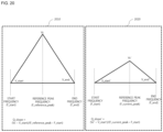
- the coil of the wireless power transmitter may have the inductance and/or series resistance component in the coil which may decrease due to environmental change, thereby changing (shifting) the resonant frequency of the coil of the wireless power transmitter. That is, a quality factor peak frequency as a frequency at which the maximum quality factor value is measured in the operating frequency band may be shifted.
- the wireless power receiver since the wireless power receiver includes a magnetic shield (shielding material) having high permeability, the high permeability may increase the inductance value measured in the coil of the wireless power transmitter. In contrast, a foreign object, which is a metallic material, decreases the inductance value.
- FIG. 5b a graph showing change in quality factor value measured when the wireless power receiver or the foreign object is placed in the charging area is shown in FIG. 5b .
- the resonant frequency f_resonant is calculated by 1 / 2 ⁇ L * C .
- the wireless power transmitter receives the reference maximum quality factor frequency pre-measured in a state in which the foreign object is not placed in the charging area, that is, the reference peak frequency, from the wireless power receiver.
- the received reference peak frequency value is compared with the measured peak frequency value in the negotiation phase 540, thereby determining whether a foreign object is present.
- the foreign object detection through peak frequency comparison is used along with a method of comparing quality factor values. If a difference between the reference quality factor value and the measured quality factor value is small, for example, if the difference is equal to or less than 10%, presence of the foreign object is determined by comparing the reference peak frequency with the measured peak frequency. In contrast, if the difference between the quality factors exceeds 10%, the wireless power transmitter immediately determines that the foreign object is present.
- the reference peak frequency is compared with the measured peak frequency to determine whether a foreign object is present. Since it is difficult to detect the foreign object using the quality factor, the wireless power receiver includes information on the reference peak frequency in a foreign object detection status packet and transmit the packet to the wireless power transmitter, and the wireless power transmitter detects the foreign object further using information on the reference peak frequency, thereby improving foreign object detection capability.
- the transmitter wakes up the receiver and transmits a digital ping for identifying whether the detected object is a wireless power receiver.
- the transmitter transitions to the selection phase 510 again.
- the transmitter transitions to the selection phase 510.
- the transmitter transitions to the identification and configuration phase 530 for identifying the receiver and collecting the configuration and status information of the receiver.
- the transmitter transitions to the selection phase 510.
- the transmitter determines whether entry into the negotiation phase 540 is necessary based on the negotiation field value of the configuration packet received in the identification and configuration phase 530.
- the transmitter Upon determining that negotiation is necessary, the transmitter transitions to the negotiation phase 540 to perform a predetermined FOD procedure.
- the transmitter upon determining that negotiation is not necessary, the transmitter immediately transitions to the power transfer phase 560.
- the transmitter receives a foreign object detection (FOD) status packet including a reference quality factor value.
- FOD status packet including a reference peak frequency value is received.
- a status packet including a reference quality factor value and a reference peak frequency value is received.
- the transmitter determines a quality factor threshold value for FO detection based on the reference quality factor value.
- the transmitter determines a peak frequency threshold value for FO detection based on the reference peak frequency value.
- the transmitter detects whether an FO is present in the charging area using the quality factor threshold value for FO detection and a currently measured quality factor value (a quality factor value measured before the ping phase) and control power transfer according to the result of FO detection. For example, when the FO is detected, power transfer is stopped, without being limited thereto.
- the transmitter transitions to the renegotiation phase 570. At this time, when renegotiation is normally terminated, the transmitter returns to the power transfer phase 560.
- FIG. 6 is a block diagram illustrating the structure of a wireless power transmitter according to an embodiment.
- the power converter 610 performs a function for converting DC power received from the power supply 660 into AC power having a predetermined strength.
- the power converter 610 includes a DC-to-DC converter 611, an inverter 612 and a frequency generator 613.
- the inverter 612 includes a half bridge inverter or a full bridge inverter.
- the embodiment is not limited thereto and the inverter may be a circuit for converting DC power into AC power having a specific operating frequency.
- the sensing unit 650 measures the voltage/current of the converted DC power and provide the voltage/current to the controller 640.
- the sensing unit 650 measures the internal temperature of the wireless power transmitter 600 and provide the measured result to the controller 640, in order to determine whether overheating has occurred.
- the controller 640 adaptively blocks power supplied from the power supply 650 based on the voltage/current value measured by the sensing unit 650 or block supply of power to the amplifier 612.
- a predetermined power blocking circuit for blocking power supplied to the amplifier 612 or blocking power supplied from the power supply 650 is further provided on one side of the power converter 610.
- the inverter 612 may convert the DC-to-DC converted DC power into AC power based on a reference AC signal generated by a frequency generator 613.
- the frequency, that is, operating frequency, of the reference AC signal may be dynamically changed according to the control signal of the controller 640.
- the wireless power transmitter 600 may adjust the operating frequency to adjust the strength of the transmitted power.
- the power reception status information may include the strength information of a rectifier output voltage, the strength information of current applied to a reception coil, etc., without being limited thereto.
- the power control signal may include a signal for requesting power increase, a signal for requesting power decrease, etc.
- the frequencies of the AC power transmitted to the transmission coils are different in the embodiment.
- the resonant frequencies of the transmission coils may be differently set using a predetermined frequency controller including a function for differently adjusting LC resonant characteristics according to the transmission coils.
- the multiplexer 621 may perform a switch function for transmitting the AC power to the transmission coil selected by the controller 640.
- the controller 640 may select a transmission coil to be used for power transfer to the wireless power receiver based on the received signal strength indicator of each transmission coil.
- the controller 640 may transmit power through time-division multiplexing of the transmission coils.
- the controller 640 may control the multiplexer 621 to transmit AC power at a specific time slot only through a specific transmission coil.
- the amount of power transmitted to the wireless power receiver may be controlled according to the length of the time slot allocated to each transmission coil.
- this is only an embodiment and the strength of the output DC power of the DC-to-DC converter 611 may be controlled during a time slot allocated to each transmission coil to control the transmission power of each wireless power receiver.
- the controller 640 may control the multiplexer 621 to sequentially transmit sensing signals through the first to n-th transmission coils 622 during a primary sensing signal transmission procedure. At this time, the controller 640 may identify a time when the sensing signal will be transmitted using a timer 655, and control the multiplexer 621 to transmit the sensing signal through the transmission coil when a sensing signal transmission time arrives. For example, the timer 650 may transmit a specific event signal to the controller 640 at predetermined periods during the ping transmission phase, and the controller 640 may control the multiplexer 621 to transmit a digital ping through the transmission coil whenever the event signal is sensed.
- the controller 640 may receive a predetermined transmission coil identifier for identifying through which transmission coil a signal strength indicator has been received from a demodulator 632 during the primary sensing signal transmission procedure, and the signal strength indicator received through the transmission coil.
- the controller 640 may control the multiplexer 621 to transmit the sensing signal only through the transmission coil(s), through which the signal strength indicator has been received during the primary sensing signal transmission procedure.
- the controller 640 may determine a transmission coil, through which a signal strength indicator having a largest value has been received, as a transmission coil, through which the sensing signal will be first transmitted in the secondary sensing signal transmission procedure, and control the multiplexer 621 according to the result of determination.
- the communication unit 630 may include at least one of a modulator 631 and a demodulator 632.
- the modulator 631 may modulate the control signal generated by the controller 640 and transmit the modulated signal to the multiplexer 621.
- a modulation method of modulating the control signal may include a frequency shift keying (FSK) modulation method, a Manchester coding modulation method, a phase shift keying (PSK) modulation method, a pulse width modulation method, a differential biphase modulation method, etc., without being limited thereto.
- the demodulator 632 may demodulate the detected signal and transmit the demodulated signal to the controller 640.
- the demodulated signal may include a signal strength indicator, an error correction (EC) indicator for power control during wireless power transmission, an end of charge (EOC) indicator, an overvoltage/overcurrent/overheating indicator, etc.
- EC error correction
- EOC end of charge
- the embodiment is not limited thereto and various types of status information for identifying the status of the wireless power receiver may be included.
- the demodulator 632 may identify through which transmission coil the demodulated signal has been received and provide a predetermined transmission coil identifier corresponding to the identified transmission coil to the controller 640.
- the demodulator 632 may demodulate the signal received through the transmission coil 622 and transmit the demodulated signal to the controller 640.
- the demodulated signal may include a signal strength indicator.
- the embodiment is not limited thereto and the demodulated signal may include various types of status information of the wireless power receiver.
- the wireless power transmitter 600 may acquire the signal strength indicator through in-band communication for performing communication with the wireless power receiver using the same frequency used for wireless power transfer.
- the wireless power transmitter 600 may transmit wireless power using the transmission coil unit 622 and exchange various types of control signals and status information with the wireless power receiver through the transmission coil unit 622.
- the wireless power transmitter 600 may further include separate coils corresponding to the first to n-th transmission coils of the transmission coil unit 622, and in-band communication with the wireless power receiver may be performed using the separate coils.
- the wireless power transmitter 600 and the wireless power receiver perform in-band communication in the description of FIG. 6 , this is merely an embodiment and short-range bidirectional communication may be performed through a frequency band different from a frequency band used for wireless power signal transmission.
- the short-range bidirectional communication may be any one of low-power Bluetooth communication, RFID communication, UWB communication and ZigBee communication.
- the power transmission unit 620 of the wireless power transmitter 600 includes the multiplexer 621 and the plurality of transmission coils 622 in the description of FIG. 6 , this is merely an embodiment and it should be noted that the power transmission unit 620 according to another embodiment may include one transmission coil.
- FIG. 7 is a block diagram illustrating the structure of a wireless power receiver interworking with the wireless power transmitter shown in FIG. 6 .
- the wireless power receiver 700 may include a reception coil 710, a rectifier 720, a DC-to-DC converter 730, a load 740, a sensing unit 750, a communication unit 760, and a main controller 770.
- the communication unit 760 may include a demodulator 761 and a modulator 762.
- the wireless power receiver 700 shown in the example of FIG. 7 is shown as exchanging information with the wireless power transmitter 600 through in-band communication, this is merely an embodiment and the communication unit 760 according to another embodiment may provide short-range bidirectional communication through a frequency band different from a frequency band used to transmit a wireless power signal.
- AC power received through the reception coil 710 may be transmitted to the rectifier 720.
- the rectifier 720 may convert the AC power into DC power and transmit the DC power to the DC-to-DC converter 730.
- the DC-to-DC converter 730 may convert the strength of the DC power output from the rectifier into a specific strength required by the load 740 and transmit the converted power to the load 740.
- the sensing unit 750 may measure the strength of the DC power output from the rectifier 720 and provide the strength to the main controller 770. In addition, the sensing unit 750 may measure the strength of current applied to the reception coil 710 according to wireless power reception and transmit the measured result to the main controller 770. In addition, the sensing unit 750 may measure the internal temperature of the wireless power receiver 700 and provide the measured temperature value to the main controller 770.
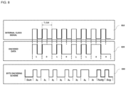
- FIG. 8 is a diagram illustrating a method of modulating and demodulating a wireless power signal according to an embodiment.
- the binary data of the packet generated by the wireless power transmission end 10 or the wireless power reception end 20 may be subjected to differential biphase encoding as denoted by reference numeral 820.
- differential biphase encoding have two status transitions to encode data bit 1 and have one state transition to encode data bit 0. That is, data bit 1 is encoded such that transition between a HI state and a LO state occurs in the rising edge and the falling edge of the clock signal and data bit 0 is encoded such that transition between the HI state and the LO state occurs in the rising edge of the clock signal.
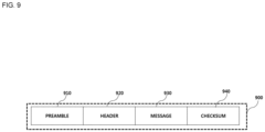
- FIG. 9 is a view illustrating a packet format according to an embodiment.
- the packet format 900 used for information exchange between the wireless power transfer end 10 and the wireless power reception end 20 may include a preamble 910 field for acquiring synchronization for demodulation of the corresponding packet and identifying an accurate start bit of the corresponding packet, a header 920 field for identifying the type of a message included in the corresponding packet, a message 930 field for transmitting the content (or payload) of the corresponding packet, and a checksum 940 field for identifying whether an error has occurred in the corresponding packet.
- a packet reception end may identify the size of the message 930 included in the corresponding packet based on the value of the header 920.
- the header 920 may be defined for each step of the wireless power transfer procedure, and the value of the header 920 may be defined as the same value in different phases of the wireless power transmission procedure.
- the header value corresponding to end power transfer of the ping phase and end power transfer of the power transfer phase is 0x02.
- the message 930 includes data to be transmitted by the transmission end of the corresponding packet.
- the data included in the message 930 field may be a report, a request, or a response, without being limited thereto.
- the packet 900 may further include at least one of transmission end identification information for identifying the transmission end for transmitting the corresponding packet and reception end identification information for identifying the reception end for receiving the corresponding packet.
- the transmission end identification information and the reception end identification may include IP address information, MAC address information, product identification information, etc.
- the embodiment is not limited thereto and information for distinguishing the reception end and the transmission end in the wireless charging system may be included.
- the packet 900 may further include predetermined group identification information for identifying a reception group if the corresponding packet is received by a plurality of apparatuses.
- FIG. 10 is a view illustrating the types of packets transmitted from the wireless power receiver to the wireless power transmitter according to an embodiment.
- the packet transmitted from the wireless power receiver to the wireless power transmitter may include a signal strength packet for transmitting the strength information of a sensed ping signal, a power transfer type (end power transfer) for requesting power transfer end from the transmitter, a power control hold-off packet for transferring information on a time until actual power is controlled after a control error packet for control is received, a configuration packet for transferring configuration information of the receiver, an identification packet and an extended identification packet for transmitting receiver identification information, a general request packet for transmitting a general request message, a specific request packet for transmitting a specific request message, an FOD status packet for transmitting a reference quality factor value for FO detection, a control error packet for controlling power transmitted by the transmitter, a renegotiation packet for starting renegotiation, a 24-bit received power packet for transmitting the strength information of the received power, and a charge status packet for transmitting the current charging status information of the load.
- a signal strength packet for transmitting the strength information of a sensed ping signal
- the packets transmitted from the wireless power receiver to the wireless power transmitter may be transmitted using in-band communication using the same frequency band as the frequency band used to transmit wireless power.
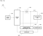
- FIG. 11-a is a diagram illustrating the basic structure of a foreign object detection apparatus (circuit) installed in a wireless power transmitter according to an embodiment.
- the foreign object detection apparatus (circuit) 1190 may include a power supply 1191, a driving unit 1192, a resonant capacitor 1193, a transmission coil 1194, a quality factor measurement unit 1195, a demodulator 1196 and a controller 1197.
- the power supply 1191 may receive and supply external power to the driving unit 1192.
- the driving unit 1192 may convert the DC power received from the power supply 1191 into AC power and control the strength of the AC power according to a control signal of the controller 1197.
- the driving unit 1192 may include a frequency oscillator for generating a specific frequency signal and an inverter for amplifying an AC signal oscillated by the frequency oscillator.
- the driving unit 1192 may change at least one of the frequency (operating frequency), duty ratio and amplitude of the AC signal according to the control signal of the controller 1197.
- the quality factor measurement unit 1195 may monitor change in inductance (or voltage or current) across the resonant capacitor 1193 and measure the quality factor value of the transmission coil. The measured current quality factor value may be transmitted to the controller 1197.
- the demodulator 1196 demodulates the signal received from the wireless power receiver and transmits the demodulated signal to the controller 1197.
- the demodulator 1196 may demodulate the FOD status packet and transmit the demodulated FOD status packet to the controller 1197.
- the controller 1197 eceives and store sthe quality factor value measured by the quality factor measurement unit 1195 in a memory. In addition, the controller 1197 reads the stored quality factor value from the memory. The controller 1197 controls the operating frequency of the driving unit 1192. By controlling the operating frequency of the driving unit 1192, the quality factor measurement unit 1195 measures the quality factor value of each operating frequency. The controller 1197 determines a frequency corresponding to a maximum quality factor value, that is, a peak frequency, based on the measured quality factor value of each operating frequency.
- the controller 1197 determines a quality factor threshold value for the wireless power receiver based on at least one of a reference quality factor value included in the FOD status packet, the operating frequency (reference peak frequency) corresponding to the maximum quality factor value, the operating frequency corresponding to a quality factor value less than the reference quality factor value by a predetermined value, for example, the operating frequency at which a quality factor value less than the reference quality factor value by 5% is measured.
- the controller 1197 compares the determined quality factor threshold value with the current quality factor value measured by the quality factor measurement unit 1195 and/or determine whether an FO is present in the charging area based on the received operating frequency (threshold frequency) and the measured or calculated operating frequency, for example, the operating frequency (peak frequency) corresponding to the maximum quality factor value or the operating frequency at which the quality factor value less than the reference quality factor value by 5% is measured.
- the controller 1197 measures the quality factor value.
- the controller 1197 measures the quality factor value of each frequency while changing the operating frequency within a predetermined operating frequency range.
- the controller 1197 measures the quality factor value using a voltage difference across the resonant capacitor 1193, without being limited thereto.
- the quality factor measurement unit 1195 includes a circuit configuration for measuring and transmitting the voltage across the resonant capacitor 1193 to the controller 1197.
- the quality factor value measured by the controller 1197 corresponds to the quality factor value of the transmission coil measured using a measurement apparatus such as an LCR meter for measuring at least one of the voltage, current, resistance, impedance, capacitance and quality factor value of an electric circuit.
- the controller 1197 continuously performs charging, stop charging and returning to the selection phase according to the result of determining whether the foreign object is present.
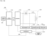
- FIG. 11-b is a diagram illustrating the structure (an extension of FIG. 11-a ) of the foreign object detection apparatus (circuit) in the wireless power transmitter according to an embodiment.
- the foreign object detection apparatus 1100 includes a power supply 1101, a DC-to-DC converter 1110 (omittable), an inverter 1120, a resonant circuit 1130, a measurement unit 1140, a communication unit 1160, an alarm unit 1175 (omittable), and a controller 1180.
- the foreign object detection apparatus 1100 according to the present embodiment is mounted in the wireless power transmission apparatus.
- the resonant circuit 1130 includes a resonant capacitor 1131 and an inductor or a transmission coil 1132 or a transmission antenna, and the communication unit 1160 includes at least one of a demodulator 1161 and a modulator 1162.
- the power supply 1101 receives DC power through an external power terminal and transmit the DC power to the DC-to-DC converter 1110.
- the wireless power transmission apparatus may adaptively determine the bridge mode according to a sensed temperature and drive the inverter 1120 in the determined bridge mode. If the temperature of the wireless power transmission apparatus exceeds a predetermined reference value while wireless power is transmitted using the half bridge mode, the controller 1180 may perform control to deactivate the half bridge mode and activate the full bridge mode. That is, the wireless power transmission apparatus may increase the voltage and decrease the strength of current flowing in the resonant circuit 1130 through the full bridge circuit for transmission of power having the same strength, thereby maintaining the internal temperature of the wireless power transmission apparatus at a reference value or less.
- the inverter 1120 may adjust the strength of the output AC power by adjusting the frequency of a reference alternating current signal used to generate the AC power under control of the controller 1180.
- the inverter 1120 may include a frequency oscillator for generating the reference alternating current signal having a specific frequency.
- the frequency oscillator may be mounted independently of the inverter 1120 and mounted at one side of the foreign object detection apparatus 1100.
- the measurement unit 1140 measures and store the quality factor value corresponding to a predetermined reference operating frequency, that is, a reference measured quality factor value, according to a control signal of the controller 1180.
- the measurement unit 1140 measures the quality factor value of each frequency within a specific operating frequency range according to a control signal of the controller 1180.
- the controller 1180 determines a peak frequency value corresponding to a maximum quality factor value and store the peak frequency value in the memory.
- the controller 1180 controls the measurement unit 1140 to measure the quality factor values at a plurality of frequencies within the operating frequency band before entering the ping phase.
- the controller 1180 identifies a frequency corresponding to a largest value among the measured quality factor values and determine the identified frequency as a current peak frequency.
- the controller 1180 determines a threshold value (or a threshold range) for determining whether a foreign object is present based on information included in the FOD status packet.
- the threshold value includes at least one of the peak frequency value and the quality factor threshold value. If the determined value is a threshold range, the threshold range include at least one of a peak frequency threshold range and a quality factor threshold range.
- the FOD status packet includes at least one of a reference quality factor value corresponding to the wireless power receiver and/or a reference peak frequency F_reference_peak value.
- the controller 1180 determines that the foreign object is present in the charging area when the calibrated reference measured quality factor value is less than the determined quality factor threshold value. In contrast, the controller 1180 determines that the foreign object is not present in the charging area when the calibrated reference measured quality factor value is equal to or greater than the determined quality factor threshold value.
- the controller 1180 stops power transfer upon determining that the foreign object is present and control the alarm unit 1175 to output a predetermined warning alarm indicating that the foreign object has been detected.
- the alarm unit 1175 may include, but is not limited to, a beeper, an LED lamp, a vibration element, a liquid crystal display, etc.
- the embodiment is not limited thereto and a predetermined alarm unit configured to inform the user that the foreign object has been detected may be provided.
- the reference quality factor value included in the FOD status packet is determined to be the smallest value of the quality factor values calculated in correspondence with the wireless power receiver at a specific position of a charging bed of a wireless power transmitter specified for standard performance test.
- the controller 1180 Upon determining that the foreign object has been removed, the controller 1180 enters the power transfer phase to perform charging of the wireless power reception device.
- the demodulator 1161 demodulates an in-band signal received from the wireless power reception apparatus and transmits the demodulated signal to the controller 1180. For example, the demodulator 1161 demodulates the FOD status packet of FIG. 14 or 15 and transmit the demodulated FOD status packet to the controller 1180.
- the foreign object detection apparatus 1100 adaptively calibrates the measured quality factor value based on the degree of shift of the peak frequency when the object is detected in the selection phase, thereby remarkably decreasing a probability of foreign object detection failure.
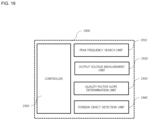
- FIG. 12 is a block diagram illustrating the structure of a foreign object detection apparatus according to another embodiment.
- the foreign object detection apparatus 1200 includes a measurement unit 1210, a search unit 1220, a communication unit 1230, a determination unit 1240, a calibration unit 1250, a detection unit 1260, a storage unit 1270 and a controller 1280. It should be noted that the components of the foreign object detection apparatus 1200 are not mandatory and more or fewer components are included.
- the measurement unit 1210 Upon detecting that an object has been placed in the charging area in the selection phase, the measurement unit 1210 temporarily stops power transfer and measure the quality factor value at a predetermined reference operating frequency.
- a current quality factor value measured at the reference operating frequency is referred to as a measured quality factor value Q_measured.
- the reference operating frequency is set to a specific frequency included in the operating frequency band. For example, if the wireless power transmission apparatus in which the foreign object detection apparatus 1200 is installed supports the WPC standard, the reference operating frequency may be 100 kHz. However, it should be noted that the embodiment is not limited thereto and the reference operating frequency may be differently defined according to the applied standard.
- the search unit 1220 Upon detecting that an object has been placed in the charging area in the selection phase, the search unit 1220 temporarily stops power transfer and search for a frequency having a maximum quality factor value in the operating frequency band.
- a frequency search offset for searching for the frequency having the maximum quality factor value may be set in units of 10 kHz * k (k being a natural number), without being limited thereto.
- a current peak frequency F_current_peak a frequency having a maximum quality factor value in an operating frequency band searched after detecting an object.
- a reference peak frequency F_reference_peak a frequency having a maximum quality factor value acquired through a preliminary experiment in a state in which only a wireless power receiver is placed in a charging area.
- the frequency having the maximum quality factor value searched within the operating frequency band has a greater value than the reference peak frequency acquired when only the wireless power receiver is placed in the charging area.
- the measured quality factor value measured by the measurement unit 1210 and the current peak frequency value searched by the search unit 1220 is stored in a predetermined recording region of the storage unit 1270.
- the communication unit 1230 receives a foreign object detection (FOD) status packet from the wireless power receiver in the negotiation phase.
- the foreign object detection status packet includes at least one of information on the reference peak frequency value and information on the reference quality factor value.
- the structure of the foreign object detection status packet will become apparent through the description of FIGs. 14 to 15 .
- the determination unit 1240 determines a quality factor threshold value for determining whether a foreign object is present based on the reference quality factor value included in the foreign object detection status packet.
- the quality factor threshold value is set to a value less than the reference quality factor value by 10%.
- this is merely an embodiment and other ratios may be applied according to the design purpose of a person skilled in the art.
- the calibration unit 1250 calibrates the quality factor threshold value Q_threshold based on a difference between a current peak frequency F_current_peak and a reference peak frequency F_reference_peak. For example, as a value obtained by subtracting the reference peak frequency value from the current peak frequency value increases, the quality factor threshold value increases.
- a specific calibration function using the difference between the current peak frequency F_current_peak and the reference peak frequency F_reference_peak as factors are predefined.
- the calibration function may be a linear function.
- the embodiment is not limited thereto and a nonlinear function such as an exponential function may be defined.
- the calibration unit 1250 sets the calibration amount of the reference measured quality factor value based on not only the difference between the current peak frequency F_current_peak and the reference peak frequency F_reference_peak but also the reference quality factor value. For example, as a value obtained by subtracting the reference peak frequency value from the current peak frequency value increases, the calibration amount of the quality factor threshold value increases.
- the quality factor threshold value calibrated by the calibration unit 1250 is referred to as a calibrated quality factor threshold value Q_threshold_fixed.
- the detection unit 1260 compares the quality factor threshold value determined by the determination unit 1240 with the calibrated quality factor threshold value calculated by the calibration unit 1250 to determine whether a foreign object is present in the charging area. For example, when the current quality factor value is less than the calibrated quality factor threshold value, the detection unit 1260 determines that the foreign object is present in the charging area. In contrast, when the current quality factor value is equal to or greater than the calibrated quality factor threshold value, the detection unit 1260 determines that the foreign object is not present in the charging area.
- the control unit 1280 controls overall operation of the foreign object detection apparatus 1200 and, particularly, controls operation of the sub-components according to the wireless power transfer phase.
- the sub-components include the measurement unit 1210, the search unit 1220, the communication unit 1230, the determination unit 1240, the calibration unit 1250 and the detection unit 1260.
- the reference quality factor value measured at the reference operating frequency varies according to the type of the wireless power reception apparatus.
- the frequency value having the maximum quality factor value in the operating frequency band varies according to the type of the wireless power reception apparatus.
- the foreign object detection apparatus 1200 receives the reference quality factor value and the reference peak frequency value corresponding to the wireless power reception apparatus through the foreign object detection (FOD) status packet.
- FOD foreign object detection
- the foreign object detection apparatus 1200 when an object is detected in the selection phase, adaptively calibrates the measured quality factor value according to the degree of shift of the peak frequency, thereby remarkably decreasing a probability of foreign object detection failure.
- FIG. 13a is a state transition diagram explaining foreign object detection in a foreign object detection apparatus according to an embodiment.
- the foreign object detection apparatus measures the current quality factor value at the reference operating frequency, that is, the measured quality factor value Q_measured.
- the foreign object detection apparatus measures the quality factor values at a plurality of frequencies before entering the ping phase 1320 and search for a frequency having a maximum quality factor value, that is, a current peak frequency F_current_peak.
- the foreign object detection apparatus periodically transmits a predetermined power signal for identifying the wireless power receiver, for example, a digital ping.
- the foreign object detection apparatus stores information on the measured quality factor values and the current peak frequency value in the predetermined recording region.
- the foreign object detection apparatus When a signal strength indicator is received in the ping phase 1320, the foreign object detection apparatus enters the identification and configuration phase 1330 to identify the wireless power receiver and to set various configuration parameters for the identified wireless power receiver.
- the foreign object detection apparatus When identification and configuration of the wireless power receiver end, the foreign object detection apparatus enters the negotiation phase 1340 to perform a foreign object detection procedure.
- the foreign object detection procedure is performed through the following four steps.
- the foreign object detection apparatus receives at least one foreign object detection status packet from the identified wireless power receiver.
- the foreign object detection status packet includes at least one of information on the reference peak frequency value and information on the reference quality factor value.
- the information on the reference quality factor value means a quality factor value measured at a reference operating frequency in a state in which the wireless power receiver is powered off. Powering off the receiver means a state in which power is not transmitted to a load.
- the information on the reference peak frequency value means a frequency having a maximum quality factor within the operating frequency band in a state in which only the wireless power receiver is placed in the charging area of a predetermined wireless power transmitter.
- the wireless power receiver stores a reference peak frequency value in advance and transmit the reference peak frequency value to the wireless power transmitter in the negotiation phase.
- step 2 the foreign object detection apparatus determines a quality factor threshold value for determining whether a foreign object is present based on the received reference quality factor value.
- the foreign object detection apparatus calibrates (or compensate for) the reference measured quality factor Q_measured_reference value based on a difference between the current peak frequency value and the reference peak frequency value.
- the calibrated Q_measured_reference value is obtained by adding the difference between the current peak frequency value and the reference peak frequency value to the Q_measured_reference value.
- the calibrated Q_measured_reference value is obtained by adding a product of the difference between the current peak frequency value and the reference peak frequency value and a predetermined weight to the Q_measured_reference value.
- step 4 the foreign object detection apparatus compares the quality factor threshold value with the calibrated reference measured quality factor value to determine whether a foreign object is present.
- FIG. 13b is a diagram illustrating a state transition diagram explaining foreign object detection in a foreign object detection apparatus according to another embodiment.
- the foreign object detection apparatus measures the current quality factor value at the reference operating frequency, that is, the measured quality factor value Q_measured.
- the foreign object detection apparatus measures the quality factor values at a plurality of frequencies before entering the ping phase 1321 and search for a frequency having a maximum quality factor value, that is, a current peak frequency F_current_peak.
- the foreign object detection apparatus periodically transmits a predetermined power signal for identifying the wireless power receiver, for example, a digital ping.
- the foreign object detection apparatus stores information on the measured quality factor values and the current peak frequency value in the predetermined recording region.
- the foreign object detection apparatus When a signal strength indicator is received in the ping phase 1321, the foreign object detection apparatus enters the identification and configuration phase 1331 to identify the wireless power receiver and set various configuration parameters for the identified wireless power receiver.
- the foreign object detection apparatus When identification and configuration of the wireless power receiver end, the foreign object detection apparatus enters the negotiation phase 1341 to perform a foreign object detection procedure.
- the foreign object detection procedure is performed through the following four steps.
- the foreign object detection apparatus receives at least one foreign object detection status packet from the identified wireless power receiver.
- the foreign object detection status packet includes at least one of information on the reference peak frequency value and information on the reference quality factor value.
- step 2 the foreign object detection apparatus determines a quality factor threshold value for determining whether a foreign object is present based on the received reference quality factor value.
- step 3 the foreign object detection apparatus compares the quality factor threshold value with the measured quality factor value to determine whether a foreign object is present.
- the foreign object detection apparatus Upon determining that the foreign object is present, the foreign object detection apparatus according to the embodiment stops power transfer and return to the selection phase 1310.
- the foreign object detection apparatus transmits a predetermined foreign object detection indicator indicating that a foreign object is present to the wireless power receiver.
- the wireless power receiver requests End of Power Transfer or ignore the indicator, that is, not transmits an Ack response signal corresponding to the foreign object detection indicator, and proceed to the subsequent phase in order to continuously perform charging.
- the foreign object detection apparatus determines whether the reference peak frequency value has been received.
- the foreign object detection apparatus determines that the reference peak frequency value has been received, when the reference peak frequency value included in the foreign object detection status packet is greater than 0.
- the foreign object detection apparatus enters the power transfer phase 1350 to start wireless charging of the wireless power receiver.
- the foreign object detection apparatus determines a peak frequency threshold value based on the reference peak frequency value.
- step 4 the foreign object detection apparatus compares the peak frequency threshold value with the current peak frequency value to determine whether a foreign object is present. When the current peak frequency value is greater than the peak frequency threshold value, it is determined that the foreign object is present. Then, the foreign object detection apparatus stops power transfer and return to the selection phase 1311. Alternatively, an indicator indicating that the foreign object is present is transmitted to the wireless power receiver, and the wireless power receiver requests End of Power Transfer or ignore the indicator and proceed to the subsequent phase in order to continuously perform charging. In contrast, upon determining that the foreign object is not present, the foreign object detection apparatus enters the power transfer phase 1351 to start wireless charging of the wireless power receiver.
- the foreign object detection apparatus upon determining that the reference peak frequency value has been received, performs the foreign object detection procedure based on the quality factor value and the foreign object detection procedure based on the peak frequency to determine whether a foreign object is present.
- the foreign object detection apparatus upon determining that the reference peak frequency value has not been received, performs only the foreign object detection procedure based on the quality factor value to determine whether a foreign object is present.
- the foreign object detection procedure is differently performed depending on whether the reference peak frequency is received, the foreign object detection procedure is performed in a manner preferred by the wireless power receiver.
- the wireless power receiver identifies the type and characteristics of the wireless power transmitter and determine a foreign object detection method optimized for the identified type and characteristics. In this case, the wireless power receiver adaptively determines whether the reference peak frequency information is transmitted or not according to the determined foreign object detection method.
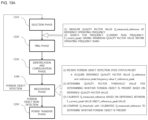
- FIG. 13c is a diagram illustrating a foreign object detection procedure according to another embodiment.
- a wireless power transmitter measures the quality factor value of a resonant circuit when an object is detected in a charging area.
- the quality factor of the resonant circuit means an amplification ratio of the input/output voltage by the resonant capacitor when AC power having a specific frequency is applied to the resonant circuit. For this, refer to the description of FIGs. 11-a and 11-b .
- the quality factor value of each frequency is measured within the operating frequency range of the wireless power transmitter.
- the wireless power transmitter determines a current quality factor value and a peak frequency (a frequency at which a maximum quality factor value is measured in the measured frequency range) through quality factor measurement and store the current quality factor value and the peak frequency in a memory.
- the wireless power transmitter receives a foreign object detection status packet.
- a foreign object detection status packet refer to the description of FIGs. 14-a to 14-b .
- the wireless power transmitter determines the quality factor threshold value based on the received reference quality factor value.
- the wireless power transmitter determines whether a foreign object is present using the quality factor threshold value and the measured quality factor value.
- the wireless power transmitter determines that a foreign object is present.
- the wireless power transmitter determines whether information on the reference peak frequency is included in the foreign object detection status packet. (see FIG. 14 )
- the wireless power transmitter determines that a foreign object is not present. At this time, a subsequent phase (e.g., calibration or power transfer) for wireless power transfer is performed.
- a subsequent phase e.g., calibration or power transfer
- the wireless power transmitter further determines whether a foreign object is present based on the received information on the reference peak frequency.
- the wireless power transmitter determines a peak frequency threshold value using the reference peak frequency value.
- the wireless power transmitter compares the peak frequency threshold value with the current peak frequency and determine that a foreign object is present when the current peak frequency is equal to or greater than the peak frequency threshold value. In contrast, when the current peak frequency is less than the peak frequency threshold value, the wireless power transmitter determines that a foreign object is not present.
- the wireless power transmitter determines whether wireless power transfer is performed or stopped.
- the procedure of determining whether a foreign object is present based on the quality factor value and the procedure of determining whether a foreign object is present based on the peak frequency is performed in a reverse order. That is, the procedure of determining whether a foreign object is present based on the peak frequency is performed first and then the procedure of determining whether a foreign object is present based on the quality factor value, thereby improving foreign object detection capability.
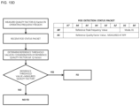
- FIG. 13d is a diagram illustrating a foreign object detection procedure according to another embodiment.
- a wireless power transmitter measures the quality factor value of a resonant circuit when an object is detected in a charging area.
- the quality factor of the resonant circuit means an amplification ratio of the input/output voltage by the resonant capacitor when AC power having a specific frequency is applied to the resonant circuit. For this, refer to the description of FIGs. 11-a and 11-b .
- the quality factor value of each frequency is measured within the operating frequency range of the wireless power transmitter.
- the wireless power transmitter stores the measured quality factor value of each frequency in a predetermined memory.
- the wireless power transmitter receives a foreign object detection status packet.
- the foreign object detection status packet includes information on a reference peak frequency corresponding to a frequency, at which a maximum quality factor value is measured within an operating frequency, and information on a reference quality factor value corresponding to the maximum quality factor value.
- the wireless power transmitter determines the quality factor threshold value based on the reference quality factor value.
- the wireless power transmitter determines whether a foreign object is present using the quality factor threshold value and the measured quality factor value.
- the measured quality factor value is a quality factor value measured at a frequency corresponding to the received reference peak frequency. Since the measured quality factor value of each frequency is stored in the memory, the wireless power transmitter identifies a frequency corresponding to the received reference peak frequency and read the measured quality factor value from the memory in correspondence with the identified frequency.
- the frequency at which the quality factor value is changed most greatly depending on presence/absence of the foreign object is a reference peak frequency. Accordingly, the wireless power receiver transmits the reference peak frequency and the quality factor value measured at the reference peak frequency to the wireless power transmitter, and the wireless power transmitter determines whether a foreign object is present based on the received information. At this time, when the reference quality factor value corresponding to the reference peak frequency at which the quality factor value is changed most greatly depending on presence/absence of the foreign object is compared with the current quality factor value, it is possible to improve foreign object detection capability.
- the current quality factor value corresponding to the reference peak frequency is measured before the ping phase, without being limited thereto.
- the wireless power transmitter determines whether a foreign object is present only using information on the reference peak frequency included in the foreign object detection status packet.
- the frequency corresponding to the maximum quality factor value among the quality factor values measured before the ping phase is greater than the reference peak frequency (which is determined in consideration of a certain tolerance range), it is determined that the foreign object is present.
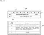
- FIG. 14-a is a view illustrating the structure of an FOD status packet message according to an embodiment.
- the FOD status packet message 1400 has a length of 2 bytes, and include a first data 1401 field having a length of 6 bits, a mode 1402 field having a length of 2 bits and a reference quality factor value 1403 field having a length of 1 byte.
- the mode 1402 field is set to a binary value of "00"
- all bits of the first data 1401 field are recorded as 0 and information corresponding to the reference quality factor value measured and determined in a state in which the wireless power receiver is powered off is recorded in the reference quality factor value 1403 field.
- the mode 1402 field is set to a binary value of "01”
- information corresponding to the reference peak frequency value meaning a frequency having a maximum quality factor value within the operating frequency band in a state in which only the wireless power receiver is placed in the charging area is recorded in the first data 1401 field.
- the reference quality factor value field 1403 information corresponding to the reference quality factor value measured and determined in a state in which the wireless power receiver is powered on is recorded in the reference quality factor value field 1403.
- the resolution of the reference peak frequency value recorded in the first data 1401 is determined based on the size of the operating frequency band.
- the first data 1401 may have a value from 0 to 63.
- the operating frequency band is 100 kHz to 260 kHz
- this may mean that the reference peak frequency is 100 kHz
- the operating frequency band for quality factor measurement may be 87 kHz to 150 kHz. At this time, any frequency value from 87 kHz to 150 kHz may be indicated in the first data 1401.
- the operating frequency band for quality factor measurement may be 87 kHz to 149 kHz. At this time, any frequency value from 87 kHz to 149 kHz may be indicated in the first data 1411.
- the wireless power transmitter may determine that a foreign object is present.
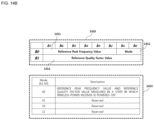
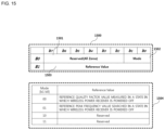
- the FOD status packet message 1500 may have a length of 2 bytes, and include a reserved 1501 field having a length of 6 bits, a mode 1502 field having a length of 2 bits and a reference value 1503 field having a length of 1 byte.
- all bits of the reserved 1501 field are recorded as "0".
- the mode 1502 field is set to "00"
- information corresponding to a reference quality factor value measured and determined in a state in which the wireless power receiver is powered off may be recorded in the reference value 1503 field.
- the mode 1502 field is set to a binary value of "01"
- information corresponding to a reference peak frequency value meaning a frequency having a maximum quality factor value within an operating frequency band in a state in which only the wireless power receiver is placed in the charging area may be recorded in the reference value 1503 field.
- the reference peak frequency may be searched in a state in which a foreign object is not placed but only the wireless power receiver which is powered off is present in the charging area.
- the foreign object detection apparatus may receive a plurality of FOD status packets in the negotiation phase to acquire the reference peak frequency value and the reference quality factor value corresponding to the wireless power receiver.
- the resolution of the reference peak frequency value may be determined based on the size of the operating frequency band, that is, the operating frequency bandwidth.
- the reference value 1503 since the reference value 1503 field has a length of 1 byte, the reference value 1503 may have a value from 0 to 127.
- the wireless power transmission apparatus having an operating frequency band of 100 kHz to 356 kHz receives an FOD status packet in which the mode 1502 value is a binary value of "01" and the reference value 1503 is set to "0x05"
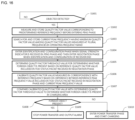
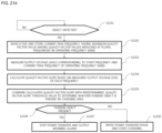
- FIG. 16 is a flowchart illustrating a foreign object detection method in a wireless power transmission apparatus according to an embodiment.
- the wireless power transmission apparatus measures and store a quality factor value corresponding to a reference operating frequency in a predetermined recording region before entering the ping phase (S1601 to S1602).
- the voltage of the transmission coil is 0.5 Vrms to 2Vrms. It is possible to prevent current leakage of the rectifier of the wireless power receiver.
- rms means root mean square.
- the wireless power transmission apparatus searches for and stores a current peak frequency having a maximum quality factor value among quality factor values measured at a plurality of frequencies in the operating frequency band in a predetermined recording region (S1603).
- a frequency offset or the number of frequencies for determining frequencies at which the quality factor value is measured for searching for the current peak frequency within the operating frequency band may vary according to the design of those skilled in the art (S1603).
- the operating frequency band may be 87 kHz to 150 kHz and the reference operating frequency may be 100kHz, without being limited thereto.
- the wireless power transmission apparatus may enter the ping phase to wirelessly transmit a digital ping signal for identifying the wireless power receiver.
- the wireless power transmission apparatus may enter the identification and configuration phase and transition to the negotiation phase when identification and configuration of the wireless power receiver end (S1604).
- the wireless power transmission apparatus may calibrate (or compensate for) the measured quality factor value, that is, the reference measured quality factor value, in correspondence with the reference operating frequency based on a difference between the reference peak frequency value included in the FOD status packet received in the negotiation phase and the current peak frequency value (S1606).
- the wireless power transmission apparatus may perform control to stop power signal transfer and to output a predetermined warning alarm indicating that the foreign object has been detected (S1608 and S1609).
- the wireless power transmission apparatus may enter the power transfer phase and start charging of the wireless power receiver (S1608 and S1610). At this time, a calibration procedure for optimizing various configuration parameters necessary for power transfer and power control may be further performed before charging of the wireless power receiver starts.
- FIG. 17 is an experimental result table illustrating a reference peak frequency of each receiver type and change in peak frequency according to placement of a foreign object.
- the peak frequency 1730 when the wireless power receiver and the foreign object are placed in the charging area is greater than the peak frequency 170 when only the wireless power receiver is placed.
- the quality factor value measured when the wireless power receiver and the foreign object are placed in the charging area is less than the quality factor value measured when only the wireless power receiver is placed.
- FIG. 18 is an experimental result graph showing change in quality factor value and peak frequency according to placement of a foreign object in a wireless charging system according to an embodiment.
- the peak frequency is greater than that of the case where only the first receiver is placed in the charging area by ⁇ f.
- ⁇ f is referred to as a peak frequency shift value.
- the quality factor value measured at the peak frequency corresponding to the state in which the first receiver and the foreign object are placed in the charging area that is, the current peak frequency
- ⁇ Q is referred to as a quality factor shift value.
- the foreign object detection apparatus may receive the quality factor value (hereinafter referred to as a first maximum quality factor value, for convenience of description) corresponding to the reference peak frequency from the wireless power receiver in the negotiation phase.
- the foreign object detection apparatus may measure the quality factor value at a plurality of frequencies within the operating frequency band to search for the current peak frequency.
- the quality factor value corresponding to the searched current peak frequency is referred to as a second maximum quality factor value.
- the foreign object detection apparatus may determine a value obtained by subtracting the second maximum quality factor value from the first maximum quality factor value as a quality factor shift value.
- a predetermined data field for additionally recording the first maximum quality factor value may be defined.
- a resonant phenomenon occurs at a peak frequency having a maximum quality factor value and power efficiency is maximized when the resonant phenomenon occurs.
- FIG. 19 is a block diagram illustrating the configuration of a foreign object detection apparatus according to another embodiment.
- the foreign object detection apparatus 1900 may include a peak frequency search unit 1910, an output voltage measurement unit 1920, a quality factor slope determination unit 1930, a foreign object detection unit 1940 and a controller 1950.
- the components of the foreign object detection apparatus 1900 are not necessarily mandatory and some components may be added or deleted.
- the output voltage measurement unit 1920 may measure the output voltage level at a specific frequency within the operating frequency band.
- the frequency at which the output voltage level is measured may include at least one of the start frequency F_start of the operating frequency band, the searched current peak frequency, and the end frequency F_end of the operating frequency band.
- the output voltage level may be the strength of the voltage applied to the transmission coil of the resonant circuit.
- the embodiment is not limited thereto and the measurement position of the output voltage level may vary according to the design of those skilled in the art.
- the quality factor slope Q_slope' may be calculated based on the output voltage level Vc' measured at the current peak frequency and the output voltage level V_end' measured at the end frequency according to another embodiment.
- the quality factor slope may be calculated by the following equation: Vc ′ ⁇ V_end ′ / F_current_peak ⁇ F_end
- the quality factor slope calculated based on the output voltage levels (or the quality factor values) measured at the start frequency and the current peak frequency is referred to as a first quality factor slope and a quality factor slope calculated based on the output voltage levels (or the quality factor values) measured at the current peak frequency and the end frequency is referred to as a second quality factor slope.
- the foreign object detection unit 1940 may compare the calculated quality factor slope with a predefined threshold value to detect a foreign object placed in the charging area.
Landscapes
- Engineering & Computer Science (AREA)
- Computer Networks & Wireless Communication (AREA)
- Power Engineering (AREA)
- Signal Processing (AREA)
- Physics & Mathematics (AREA)
- Quality & Reliability (AREA)
- Electromagnetism (AREA)
- Computer Security & Cryptography (AREA)
- Charge And Discharge Circuits For Batteries Or The Like (AREA)
- Investigating Or Analyzing Materials By The Use Of Magnetic Means (AREA)
- General Physics & Mathematics (AREA)
Claims (6)
- Drahtlosleistungsempfänger (20, 700), umfassend:eine Drahtloskommunikationseinheit, die konfiguriert ist, um mit einem Drahtlosleistungssender (10, 600) zu kommunizieren;einen Speicher, der konfiguriert ist, um einen ersten Referenzwert zu speichern, der eines von einem Referenzgütefaktor (Q_reference) und einer Referenzspitzenfrequenz (F_reference_peak) des Drahtlosleistungsempfängers (20, 700) einschließt, und um einen zweiten Referenzwert zu speichern, der das andere des Referenzgütefaktors (Q_reference) und der Referenzspitzenfrequenz (F_reference_peak) einschließt; undeine Steuerung, die konfiguriert ist, um über die Drahtloskommunikationseinheit ein erstes Fremdkörpererkennungsstatuspaket (1500) und ein zweites Fremdkörpererkennungsstatuspaket (1500) an den Drahtlosleistungssender (10, 600) zu senden,wobei das erste Fremdkörpererkennungsstatuspaket (1500) den ersten Referenzwert einschließt,wobei das zweite Fremdkörpererkennungsstatuspaket (1500) den zweiten Referenzwert einschließt,dadurch gekennzeichnet, dassdie Steuerung ferner konfiguriert ist, um über die Drahtloskommunikationseinheit eine Fremdkörpererkennungsanzeigeeinrichtung zu empfangen, die anzeigt, dass ein Fremdkörper in einem Ladebereich des Drahtlosleistungssenders (10, 600) vorhanden ist,dass das erste Fremdkörpererkennungsstatuspaket (1500) Modusinformationen einschließt, die anzeigen, dass der erste Referenzwert in dem ersten Fremdkörpererkennungsstatuspaket (1500) eingeschlossen ist,dass das zweite Fremdkörpererkennungsstatuspaket (1500) Modusinformationen einschließt, die anzeigen, dass der zweite Referenzwert in dem zweiten Fremdkörpererkennungsstatuspaket (1500) eingeschlossen ist, unddass die Fremdkörpererkennungsanzeigeeinrichtung basierend auf dem ersten Fremdkörpererkennungsstatuspaket (1500) und dann dem zweiten Fremdkörpererkennungsstatuspaket (1500) bestimmt wird.
- Drahtlosleistungsempfänger (20, 700) nach Anspruch 1, wobei, falls die Fremdkörpererkennungsanzeigeeinrichtung anzeigt, dass der Fremdkörper in dem Ladebereich vorhanden ist, der Drahtlosladevorgang aufgrund des Fremdkörpers angehalten wird.
- Drahtlosleistungsempfänger (20, 700) nach Anspruch 1, wobei die Steuerung konfiguriert ist, um zu steuern, dass die Drahtloskommunikationseinheit als Reaktion auf die Fremdkörpererkennungsanzeige kein ACK-Antwortsignal an den Drahtlosleistungssender (10, 600) zum Einleiten einer Stromübertragungsphase sendet, oder um anzufordern, dass der Drahtlosleistungssender (10, 600) einen Drahtlosladevorgang beendet, wenn die Fremdkörpererkennungsanzeigeeinrichtung anzeigt, dass der Fremdkörper in dem Ladebereich vorhanden ist.
- Drahtlosleistungsempfänger (20, 700) nach Anspruch 1, wobei die Fremdkörpererkennungsanzeigeeinrichtung anzeigt, dass der Fremdkörper in dem Ladebereich vorhanden ist, wenn eines von einem gemessenen Gütefaktor und einer gemessenen Spitzenfrequenz eines Leistungssignals, das durch den Drahtlosleistungssender (10, 600) gesendet wird, größer als ein erster Schwellenwert ist, und
wobei die Fremdkörpererkennungsanzeigeeinrichtung anzeigt, dass der Fremdkörper nicht in dem Ladebereich vorhanden ist, wenn das andere des gemessenen Gütefaktors und der gemessenen Spitzenfrequenz des Leistungssignals, das durch den Drahtlosleistungssender (10, 600) gesendet wird, gleich oder kleiner als ein zweiter Schwellenwert ist. - Drahtlosleistungsempfänger (20, 700) nach Anspruch 1, wobei eine Spitzenfrequenz eines Leistungssignals, das durch den Drahtlosleistungssender (10, 600) gesendet wird, von der Referenzspitzenfrequenz (F_reference_peak) verschoben ist, wenn der Fremdkörper in dem Ladebereich vorhanden ist.
- Drahtlosleistungsempfänger (20, 700) nach Anspruch 1, wobei die Referenzspitzenfrequenz (F_reference_peak) eine Frequenz einschließt, die einem Q-Faktor in einem Betriebsfrequenzbereich des Drahtlosleistungssenders (10, 600) entspricht.
Applications Claiming Priority (5)
| Application Number | Priority Date | Filing Date | Title |
|---|---|---|---|
| KR20160106789 | 2016-08-23 | ||
| KR1020160117518A KR102617560B1 (ko) | 2016-08-23 | 2016-09-12 | 이물질 검출 방법 및 그를 위한 장치 및 시스템 |
| EP21159221.7A EP3863147B1 (de) | 2016-08-23 | 2017-08-23 | Drahtloser energieempfänger |
| PCT/KR2017/009208 WO2018038531A1 (ko) | 2016-08-23 | 2017-08-23 | 이물질 검출 방법 및 그를 위한 장치 및 시스템 |
| EP17843951.9A EP3506460B1 (de) | 2016-08-23 | 2017-08-23 | Verfahren zur detektion von fremdmaterial sowie sender zur drahtlosen leistungsübertragung |
Related Parent Applications (3)
| Application Number | Title | Priority Date | Filing Date |
|---|---|---|---|
| EP21159221.7A Division EP3863147B1 (de) | 2016-08-23 | 2017-08-23 | Drahtloser energieempfänger |
| EP21159221.7A Division-Into EP3863147B1 (de) | 2016-08-23 | 2017-08-23 | Drahtloser energieempfänger |
| EP17843951.9A Division EP3506460B1 (de) | 2016-08-23 | 2017-08-23 | Verfahren zur detektion von fremdmaterial sowie sender zur drahtlosen leistungsübertragung |
Publications (4)
| Publication Number | Publication Date |
|---|---|
| EP4236025A2 EP4236025A2 (de) | 2023-08-30 |
| EP4236025A3 EP4236025A3 (de) | 2023-10-11 |
| EP4236025B1 true EP4236025B1 (de) | 2025-07-09 |
| EP4236025C0 EP4236025C0 (de) | 2025-07-09 |
Family
ID=61727607
Family Applications (19)
| Application Number | Title | Priority Date | Filing Date |
|---|---|---|---|
| EP23186859.7A Pending EP4239851A3 (de) | 2016-08-23 | 2017-08-23 | Verfahren zur erkennung von fremdkörpern sowie vorrichtung und system dafür |
| EP23186851.4A Active EP4239843B1 (de) | 2016-08-23 | 2017-08-23 | Leistungsübertragungsverfahren für einen drahtlosen energieübertrager |
| EP23186853.0A Active EP4239845B1 (de) | 2016-08-23 | 2017-08-23 | Verfahren zur empfangen drahtloser energieübertragung |
| EP23186852.2A Active EP4239844B1 (de) | 2016-08-23 | 2017-08-23 | Drahtloser energieübertrager |
| EP23186854.8A Active EP4239846B1 (de) | 2016-08-23 | 2017-08-23 | Drahtloser energieempfänger |
| EP21159221.7A Active EP3863147B1 (de) | 2016-08-23 | 2017-08-23 | Drahtloser energieempfänger |
| EP23186860.5A Pending EP4239852A3 (de) | 2016-08-23 | 2017-08-23 | Verfahren zur erkennung von fremdkörpern sowie vorrichtung und system dafür |
| EP23178394.5A Active EP4236025B1 (de) | 2016-08-23 | 2017-08-23 | Drahtloser energieempfänger |
| EP23178395.2A Active EP4236026B1 (de) | 2016-08-23 | 2017-08-23 | Drahtloser energiesender |
| EP23186847.2A Active EP4239839B1 (de) | 2016-08-23 | 2017-08-23 | Verfahren zur erkennung von fremdkörpern sowie vorrichtung und system dafür |
| EP17843951.9A Active EP3506460B1 (de) | 2016-08-23 | 2017-08-23 | Verfahren zur detektion von fremdmaterial sowie sender zur drahtlosen leistungsübertragung |
| EP23178399.4A Active EP4236027B1 (de) | 2016-08-23 | 2017-08-23 | Verfahren zur drahtlosen energieübertragung |
| EP23186855.5A Active EP4239847B1 (de) | 2016-08-23 | 2017-08-23 | Leistungsübertragungsverfahren für einen drahtlosen energieübertrager |
| EP23186857.1A Active EP4239849B1 (de) | 2016-08-23 | 2017-08-23 | Verfahren zur empfangen drahtloser energieübertragung |
| EP23186856.3A Active EP4239848B1 (de) | 2016-08-23 | 2017-08-23 | Drahtloser energieübertrager |
| EP23186848.0A Active EP4239840B1 (de) | 2016-08-23 | 2017-08-23 | Verfahren zur drahtloser energieübertragung zur erkennung von fremdkörpern |
| EP23186850.6A Active EP4239842B1 (de) | 2016-08-23 | 2017-08-23 | Verfahren zum empfangen drahtloser energieübertragung |
| EP23186849.8A Active EP4239841B1 (de) | 2016-08-23 | 2017-08-23 | Drahtloser energieempfänger |
| EP23186858.9A Active EP4239850B1 (de) | 2016-08-23 | 2017-08-23 | Drahtloser energieempfänger |
Family Applications Before (7)
| Application Number | Title | Priority Date | Filing Date |
|---|---|---|---|
| EP23186859.7A Pending EP4239851A3 (de) | 2016-08-23 | 2017-08-23 | Verfahren zur erkennung von fremdkörpern sowie vorrichtung und system dafür |
| EP23186851.4A Active EP4239843B1 (de) | 2016-08-23 | 2017-08-23 | Leistungsübertragungsverfahren für einen drahtlosen energieübertrager |
| EP23186853.0A Active EP4239845B1 (de) | 2016-08-23 | 2017-08-23 | Verfahren zur empfangen drahtloser energieübertragung |
| EP23186852.2A Active EP4239844B1 (de) | 2016-08-23 | 2017-08-23 | Drahtloser energieübertrager |
| EP23186854.8A Active EP4239846B1 (de) | 2016-08-23 | 2017-08-23 | Drahtloser energieempfänger |
| EP21159221.7A Active EP3863147B1 (de) | 2016-08-23 | 2017-08-23 | Drahtloser energieempfänger |
| EP23186860.5A Pending EP4239852A3 (de) | 2016-08-23 | 2017-08-23 | Verfahren zur erkennung von fremdkörpern sowie vorrichtung und system dafür |
Family Applications After (11)
| Application Number | Title | Priority Date | Filing Date |
|---|---|---|---|
| EP23178395.2A Active EP4236026B1 (de) | 2016-08-23 | 2017-08-23 | Drahtloser energiesender |
| EP23186847.2A Active EP4239839B1 (de) | 2016-08-23 | 2017-08-23 | Verfahren zur erkennung von fremdkörpern sowie vorrichtung und system dafür |
| EP17843951.9A Active EP3506460B1 (de) | 2016-08-23 | 2017-08-23 | Verfahren zur detektion von fremdmaterial sowie sender zur drahtlosen leistungsübertragung |
| EP23178399.4A Active EP4236027B1 (de) | 2016-08-23 | 2017-08-23 | Verfahren zur drahtlosen energieübertragung |
| EP23186855.5A Active EP4239847B1 (de) | 2016-08-23 | 2017-08-23 | Leistungsübertragungsverfahren für einen drahtlosen energieübertrager |
| EP23186857.1A Active EP4239849B1 (de) | 2016-08-23 | 2017-08-23 | Verfahren zur empfangen drahtloser energieübertragung |
| EP23186856.3A Active EP4239848B1 (de) | 2016-08-23 | 2017-08-23 | Drahtloser energieübertrager |
| EP23186848.0A Active EP4239840B1 (de) | 2016-08-23 | 2017-08-23 | Verfahren zur drahtloser energieübertragung zur erkennung von fremdkörpern |
| EP23186850.6A Active EP4239842B1 (de) | 2016-08-23 | 2017-08-23 | Verfahren zum empfangen drahtloser energieübertragung |
| EP23186849.8A Active EP4239841B1 (de) | 2016-08-23 | 2017-08-23 | Drahtloser energieempfänger |
| EP23186858.9A Active EP4239850B1 (de) | 2016-08-23 | 2017-08-23 | Drahtloser energieempfänger |
Country Status (6)
| Country | Link |
|---|---|
| US (18) | US11005303B2 (de) |
| EP (19) | EP4239851A3 (de) |
| JP (19) | JP7146737B2 (de) |
| KR (18) | KR102617560B1 (de) |
| CN (19) | CN116742825A (de) |
| PL (6) | PL4239842T3 (de) |
Families Citing this family (58)
| Publication number | Priority date | Publication date | Assignee | Title |
|---|---|---|---|---|
| CN114786289A (zh) * | 2015-04-17 | 2022-07-22 | 豪倍照明公司 | 应急发光单元及其控制方法 |
| DE102015213981A1 (de) * | 2015-07-24 | 2017-01-26 | Conti Temic Microelectronic Gmbh | Detektion eines Fremdkörpers in einem elektromagnetischen Feld, insbesondere mit Hilfe eines NFC Chips |
| US10199881B2 (en) * | 2015-10-23 | 2019-02-05 | Mediatek Inc. | Robust foreign objects detection |
| KR102617560B1 (ko) * | 2016-08-23 | 2023-12-27 | 엘지이노텍 주식회사 | 이물질 검출 방법 및 그를 위한 장치 및 시스템 |
| US20180191203A1 (en) * | 2017-01-03 | 2018-07-05 | Hyundai Motor Company | Apparatus and method for detecting foreign object using reflected or refracted laser in wireless power transfer system of electric vehicle |
| US10833539B2 (en) * | 2017-09-27 | 2020-11-10 | Wits Co., Ltd. | Mobile terminal, communications module and control method of mobile terminal |
| US10714985B2 (en) | 2017-10-11 | 2020-07-14 | Spark Connected LLC | Wireless power transfer system and method |
| EP3547487B1 (de) * | 2018-03-29 | 2020-03-25 | NOK9 ip AB | Prüfungsvorrichtung zum prüfen einer vorrichtung zur drahtlosen stromübertragung und zugehöriges verfahren |
| WO2019203420A1 (ko) | 2018-04-18 | 2019-10-24 | 엘지전자 주식회사 | 무선전력 전송 시스템에서 이물질 검출을 수행하는 장치 및 방법 |
| KR102509314B1 (ko) * | 2018-05-16 | 2023-03-14 | 엘지이노텍 주식회사 | 무선 전력 전송 제어 방법 및 장치 |
| US10855117B2 (en) * | 2018-05-22 | 2020-12-01 | WitTricity Corporation | Extended foreign object detection signal processing |
| WO2019225806A1 (ko) * | 2018-05-23 | 2019-11-28 | 엘지이노텍(주) | 무선 전력 송신 방법 및 장치 |
| TWI738029B (zh) | 2018-07-19 | 2021-09-01 | 新加坡商聯發科技(新加坡)私人有限公司 | 無線功率傳輸系統之異物偵測技術 |
| WO2020015746A1 (en) | 2018-07-19 | 2020-01-23 | Mediatek Singapore Pte. Ltd. | Detecting foreign objects in wireless power transfer systems |
| EP3637583A1 (de) * | 2018-10-09 | 2020-04-15 | Koninklijke Philips N.V. | Drahtlose stromübertragung |
| KR102532469B1 (ko) * | 2018-11-19 | 2023-05-12 | 엘지전자 주식회사 | 무선 전력 전송 장치 |
| JP7278756B2 (ja) * | 2018-11-28 | 2023-05-22 | キヤノン株式会社 | 受電装置、受電装置の制御方法及びプログラム |
| KR102735598B1 (ko) * | 2018-12-24 | 2024-11-29 | 엘지이노텍 주식회사 | 무선 전력 전송 제어 방법 및 장치 |
| CN109638942B (zh) * | 2018-12-27 | 2020-05-19 | 电子科技大学 | 一种无源无线氢气传感标签及系统 |
| US11509169B2 (en) | 2019-02-13 | 2022-11-22 | Spark Connected LLC | Sub-surface wireless charging |
| KR102205164B1 (ko) * | 2019-02-19 | 2021-01-19 | 엘지전자 주식회사 | 무선 전력 전송 장치 및 그 제어방법 |
| US11152823B2 (en) | 2019-04-01 | 2021-10-19 | Spark Connected LLC | Translation unit for wireless power transfer |
| KR102622769B1 (ko) | 2019-04-29 | 2024-01-10 | 엘지전자 주식회사 | 무선전력 수신장치, 무선전력 전송장치 및 이를 이용한 무선전력 전송방법 |
| USD927053S1 (en) * | 2019-05-15 | 2021-08-03 | Tuanfang Liu | Electronic cigarette |
| USD927054S1 (en) * | 2019-05-15 | 2021-08-03 | Tuanfang Liu | Electronic cigarette |
| US11296550B2 (en) * | 2019-07-23 | 2022-04-05 | Aira, Inc. | Detection of device removal from a surface of a multi-coil wireless charging device |
| US11258307B2 (en) | 2019-08-14 | 2022-02-22 | Apple Inc. | Wireless power system with foreign object detection |
| US11336127B2 (en) | 2019-08-15 | 2022-05-17 | Mediatek Singapore Pte. Ltd. | Calibration of foreign object detection in wireless power systems with authentication |
| US11881719B2 (en) | 2019-09-12 | 2024-01-23 | Spark Connected LLC | Wireless power transfer object detection circuit and method |
| EP3793061A1 (de) * | 2019-09-16 | 2021-03-17 | NXP USA, Inc. | Verfahren und vorrichtung zur erkennung von fremdkörpern |
| WO2021113383A1 (en) * | 2019-12-03 | 2021-06-10 | Apple Inc. | Wireless power systems with foreign object detection |
| JP7457493B2 (ja) * | 2019-12-10 | 2024-03-28 | キヤノン株式会社 | 送電装置、受電装置、それらの制御方法およびプログラム |
| US11056922B1 (en) | 2020-01-03 | 2021-07-06 | Nucurrent, Inc. | Wireless power transfer system for simultaneous transfer to multiple devices |
| EP4099542A4 (de) * | 2020-01-29 | 2023-12-27 | LG Electronics Inc. | Gerät und verfahren zur ermöglichung von bandexterner kommunikation in einem drahtlosen ladegerät, verfahren und system |
| US11515739B2 (en) | 2020-02-14 | 2022-11-29 | Spark Connected LLC | FOD and wireless power transfer calibration |
| CN115244821B (zh) | 2020-03-03 | 2024-04-09 | 微芯片技术股份有限公司 | 多线圈无线充电系统中的低功率对象检测 |
| JP7731891B2 (ja) * | 2020-03-06 | 2025-09-01 | エルジー エレクトロニクス インコーポレイティド | 無線電力送信装置、無線電力送信方法、無線電力受信装置及び無線電力受信方法 |
| US12068631B2 (en) | 2020-04-13 | 2024-08-20 | Spark Connected LLC | Alignment method for sub-surface wireless charger |
| US12053055B2 (en) | 2020-05-15 | 2024-08-06 | Spark Connected LLC | Dual function wireless power and thermal receiver |
| US11201502B1 (en) | 2020-06-16 | 2021-12-14 | Nxp Usa, Inc. | Hybrid wireless power transfer system for an electronic device |
| US11888331B2 (en) | 2020-07-01 | 2024-01-30 | Spark Connected LLC | Sub-surface wireless charging and associated method |
| US12046922B2 (en) * | 2020-08-16 | 2024-07-23 | Aira, Inc. | Adaptive foreign object detection avoidance in a multi-coil wireless charging device |
| CN112583141B (zh) * | 2020-11-25 | 2023-06-27 | 华为数字能源技术有限公司 | 一种无线充电设备、充电底座及异物检测方法 |
| WO2022140609A1 (en) * | 2020-12-22 | 2022-06-30 | Nucurrent, Inc. | Detection of foreign objects in large charging volume applications |
| US11876386B2 (en) | 2020-12-22 | 2024-01-16 | Nucurrent, Inc. | Detection of foreign objects in large charging volume applications |
| US11881716B2 (en) | 2020-12-22 | 2024-01-23 | Nucurrent, Inc. | Ruggedized communication for wireless power systems in multi-device environments |
| CN115333180B (zh) * | 2021-03-04 | 2025-04-29 | 吉成无线(深圳)有限公司 | 基于中继线圈的远距离自适应asm通信解调的自学习控制方法及无线充电器 |
| US20220379761A1 (en) * | 2021-05-25 | 2022-12-01 | Hyundai Motor Company | Apparatus and method for communication association, positioning, and pairing for wireless power transfer |
| US12334753B2 (en) | 2021-08-13 | 2025-06-17 | Samsung Electronics Co., Ltd | Method of detecting foreign object and electronic device |
| CN116032034A (zh) * | 2021-10-27 | 2023-04-28 | 华为数字能源技术有限公司 | 一种异物检测装置、方法及无线充电器 |
| EP4436006A4 (de) * | 2021-11-16 | 2025-12-10 | Lg Electronics Inc | Verfahren und vorrichtung zur erzeugung eines schlitzes in einem drahtlosen stromübertragungssystem |
| US20230163635A1 (en) * | 2021-11-19 | 2023-05-25 | Samsung Electronics Co., Ltd. | Wireless power transmission device and operating method of wireless power transmitter |
| US12003116B2 (en) | 2022-03-01 | 2024-06-04 | Nucurrent, Inc. | Wireless power transfer system for simultaneous transfer to multiple devices with cross talk and interference mitigation |
| US11831174B2 (en) | 2022-03-01 | 2023-11-28 | Nucurrent, Inc. | Cross talk and interference mitigation in dual wireless power transmitter |
| US20240343147A1 (en) * | 2023-04-12 | 2024-10-17 | GM Global Technology Operations LLC | Detection and mitigation of charging signal oscillations during offboard charging event |
| TWI848763B (zh) * | 2023-07-06 | 2024-07-11 | 立錡科技股份有限公司 | 可偵測無線電源接收器與異物之無線電源發射電路及方法 |
| US20250337279A1 (en) * | 2024-04-26 | 2025-10-30 | Nucurrent, Inc. | Efficiency Enhancements for Large Area Wireless Power Transfer Systems |
| CN118971412B (zh) * | 2024-10-17 | 2025-03-11 | 成都市易冲半导体有限公司 | 异物检测方法、装置及无线充电系统 |
Family Cites Families (44)
| Publication number | Priority date | Publication date | Assignee | Title |
|---|---|---|---|---|
| JP2008123239A (ja) * | 2006-11-13 | 2008-05-29 | Hitachi Ltd | キーワード抽出検索方式およびモバイル端末 |
| JP2009201328A (ja) | 2008-02-25 | 2009-09-03 | Toshiba Corp | 充電装置及び充電システム |
| JP4725604B2 (ja) * | 2008-06-25 | 2011-07-13 | セイコーエプソン株式会社 | 送電制御装置、送電装置、受電制御装置、受電装置及び電子機器 |
| JP4725664B2 (ja) | 2008-06-25 | 2011-07-13 | セイコーエプソン株式会社 | 送電制御装置、送電装置、受電制御装置、受電装置、電子機器、送電制御方法、及び受電制御方法 |
| KR101059657B1 (ko) * | 2009-10-07 | 2011-08-25 | 삼성전기주식회사 | 무선 전력 송수신 장치 및 그 방법 |
| JP2012016125A (ja) | 2010-06-30 | 2012-01-19 | Panasonic Electric Works Co Ltd | 非接触給電システム及び非接触給電システムの金属異物検出装置 |
| JP4996722B2 (ja) | 2010-06-30 | 2012-08-08 | 株式会社東芝 | 電力伝送システム及び送電装置 |
| JP5071574B1 (ja) * | 2011-07-05 | 2012-11-14 | ソニー株式会社 | 検知装置、受電装置、非接触電力伝送システム及び検知方法 |
| JP6035711B2 (ja) * | 2011-07-21 | 2016-11-30 | ソニー株式会社 | 検知装置、受電装置、送電装置、非接触電力伝送システム及び検知方法 |
| JP5840886B2 (ja) * | 2011-07-25 | 2016-01-06 | ソニー株式会社 | 検知装置、受電装置、送電装置、非接触電力伝送システム及び検知方法 |
| JP2013059236A (ja) * | 2011-09-09 | 2013-03-28 | Sony Corp | 検知装置、受電装置、送電装置、非接触電力伝送システム及び検知方法 |
| JP2013070580A (ja) * | 2011-09-26 | 2013-04-18 | Sony Corp | 受電装置、送電装置、非接触電力伝送システム及び非接触電力伝送方法 |
| US9450648B2 (en) | 2011-10-13 | 2016-09-20 | Integrated Device Technology, Inc. | Apparatus, system, and method for detecting a foreign object in an inductive wireless power transfer system |
| JP5838768B2 (ja) * | 2011-11-30 | 2016-01-06 | ソニー株式会社 | 検知装置、受電装置、非接触電力伝送システム及び検知方法 |
| KR101213649B1 (ko) * | 2011-12-16 | 2012-12-18 | 전자부품연구원 | 이물질 및 무선 충전기기의 이동을 감지할 수 있는 자기공진유도 방식을 이용한 무선 전력전송 장치 및 방법 |
| JP5967989B2 (ja) * | 2012-03-14 | 2016-08-10 | ソニー株式会社 | 検知装置、受電装置、送電装置及び非接触給電システム |
| JP5915904B2 (ja) | 2012-06-22 | 2016-05-11 | ソニー株式会社 | 処理装置、処理方法、及び、プログラム |
| JP2015223009A (ja) | 2012-09-15 | 2015-12-10 | 三洋電機株式会社 | 無接点充電方法 |
| US9178361B2 (en) | 2012-09-27 | 2015-11-03 | ConvenientPower, Ltd. | Methods and systems for detecting foreign objects in a wireless charging system |
| KR102051682B1 (ko) | 2013-03-15 | 2019-12-03 | 지이 하이브리드 테크놀로지스, 엘엘씨 | 무선 전력 전송 시스템에서 이물질 감지 장치 및 방법 |
| JP2014220944A (ja) | 2013-05-09 | 2014-11-20 | キヤノン株式会社 | 給電装置、電子機器、方法及びプログラム |
| CN111431639A (zh) * | 2013-06-06 | 2020-07-17 | 索尼公司 | 无线通信方法和无线通信设备 |
| KR101604310B1 (ko) | 2013-06-16 | 2016-03-17 | 엘지전자 주식회사 | 무선 전력 전송방법, 무선 전력 전송장치 및 무선 충전 시스템 |
| WO2014203346A1 (ja) | 2013-06-19 | 2014-12-24 | ルネサスエレクトロニクス株式会社 | 送電装置、非接触給電システム、及び制御方法 |
| JP6387222B2 (ja) * | 2013-08-28 | 2018-09-05 | ソニー株式会社 | 給電装置、受電装置、給電システム、および、給電装置の制御方法 |
| EP3050190B1 (de) * | 2013-09-24 | 2018-11-07 | Powermat Technologies Ltd. | System und verfahren zur erhöhung des betriebsbereichs einer induktiven energieübertragung |
| KR101667725B1 (ko) * | 2013-11-21 | 2016-10-20 | 엘지전자 주식회사 | 무선 전력 전송 장치 및 그 제어 방법 |
| US10097041B2 (en) | 2013-10-31 | 2018-10-09 | Lg Electronics Inc. | Wireless power transmission device and control method therefor |
| EP3009866B1 (de) * | 2014-03-05 | 2022-05-04 | Panasonic Intellectual Property Management Co., Ltd. | Fremdkörperdetektor, stromsender, stromempfänger und drahtloses stromübertragungssystem |
| US10103584B2 (en) * | 2014-03-25 | 2018-10-16 | Koninklijke Philips N.V. | Wireless inductive power transfer |
| KR102166881B1 (ko) * | 2014-04-03 | 2020-10-16 | 엘지이노텍 주식회사 | 무선 전력 송신 장치 |
| US9939539B2 (en) | 2014-04-04 | 2018-04-10 | Texas Instruments Incorporated | Wireless power receiver and/or foreign object detection by a wireless power transmitter |
| JP6273040B2 (ja) | 2014-04-11 | 2018-01-31 | エルジー エレクトロニクス インコーポレイティド | 無線電力送信機及び無線電力送信方法 |
| CN105226843B (zh) * | 2014-05-27 | 2017-09-15 | 松下知识产权经营株式会社 | 无线电力传输系统以及无线电力传输系统的送电装置 |
| WO2015194889A1 (en) * | 2014-06-20 | 2015-12-23 | Lg Electronics Inc. | Wireless power transfer method, apparatus and system |
| KR101750870B1 (ko) | 2014-06-20 | 2017-06-26 | 엘지전자 주식회사 | 무선 전력 전송방법, 무선 전력 전송장치 및 무선 충전 시스템 |
| US9505315B2 (en) * | 2014-08-04 | 2016-11-29 | Qualcomm Incorporated | Wireless charging based on selective activation of transmit antennas |
| EP3180835A4 (de) * | 2014-08-12 | 2017-09-13 | PowerbyProxi Limited | System und verfahren zur leistungsübertragung |
| KR102197580B1 (ko) * | 2014-10-07 | 2021-01-04 | 주식회사 히타치엘지 데이터 스토리지 코리아 | 무선 전력 전송 장치 및 방법 |
| US10132650B2 (en) * | 2015-01-22 | 2018-11-20 | Integrated Device Technology, Inc. | Apparatuses and related methods for detecting magnetic flux field characteristics with a wireless power transmitter |
| EP3160072B1 (de) * | 2015-10-19 | 2019-10-02 | Yamar Electronics Ltd. | Sender-empfänger für asynchrone datenübertragung über einen rauschenden kanal |
| US10199881B2 (en) * | 2015-10-23 | 2019-02-05 | Mediatek Inc. | Robust foreign objects detection |
| CN109952503B (zh) | 2016-07-01 | 2022-09-09 | Lg伊诺特有限公司 | 用于检测异物的方法及其设备和系统 |
| KR102617560B1 (ko) * | 2016-08-23 | 2023-12-27 | 엘지이노텍 주식회사 | 이물질 검출 방법 및 그를 위한 장치 및 시스템 |
-
2016
- 2016-09-12 KR KR1020160117518A patent/KR102617560B1/ko active Active
-
2017
- 2017-08-23 EP EP23186859.7A patent/EP4239851A3/de active Pending
- 2017-08-23 CN CN202310786885.1A patent/CN116742825A/zh active Pending
- 2017-08-23 CN CN202310799931.1A patent/CN116846097A/zh active Pending
- 2017-08-23 EP EP23186851.4A patent/EP4239843B1/de active Active
- 2017-08-23 CN CN202310786573.0A patent/CN116799978A/zh active Pending
- 2017-08-23 EP EP23186853.0A patent/EP4239845B1/de active Active
- 2017-08-23 CN CN202210954377.5A patent/CN115347688B/zh active Active
- 2017-08-23 CN CN202310798265.XA patent/CN116707172A/zh active Pending
- 2017-08-23 EP EP23186852.2A patent/EP4239844B1/de active Active
- 2017-08-23 PL PL23186850.6T patent/PL4239842T3/pl unknown
- 2017-08-23 CN CN201780052155.1A patent/CN109804530B/zh active Active
- 2017-08-23 CN CN202310790288.6A patent/CN116742826A/zh active Pending
- 2017-08-23 EP EP23186854.8A patent/EP4239846B1/de active Active
- 2017-08-23 CN CN202310771314.0A patent/CN116707169A/zh active Pending
- 2017-08-23 CN CN202310798829.XA patent/CN116846096A/zh active Pending
- 2017-08-23 EP EP21159221.7A patent/EP3863147B1/de active Active
- 2017-08-23 PL PL23186847.2T patent/PL4239839T3/pl unknown
- 2017-08-23 EP EP23186860.5A patent/EP4239852A3/de active Pending
- 2017-08-23 CN CN202310801235.XA patent/CN116846098A/zh active Pending
- 2017-08-23 PL PL23178395.2T patent/PL4236026T3/pl unknown
- 2017-08-23 CN CN202310786288.9A patent/CN116722662A/zh active Pending
- 2017-08-23 CN CN202310772498.2A patent/CN116707170A/zh active Pending
- 2017-08-23 EP EP23178394.5A patent/EP4236025B1/de active Active
- 2017-08-23 CN CN202310791774.XA patent/CN116722663A/zh active Pending
- 2017-08-23 JP JP2019511424A patent/JP7146737B2/ja active Active
- 2017-08-23 EP EP23178395.2A patent/EP4236026B1/de active Active
- 2017-08-23 EP EP23186847.2A patent/EP4239839B1/de active Active
- 2017-08-23 CN CN202310797406.6A patent/CN116707171A/zh active Pending
- 2017-08-23 EP EP17843951.9A patent/EP3506460B1/de active Active
- 2017-08-23 CN CN202310798700.9A patent/CN116742829A/zh active Pending
- 2017-08-23 EP EP23178399.4A patent/EP4236027B1/de active Active
- 2017-08-23 CN CN202310798705.1A patent/CN116707173A/zh active Pending
- 2017-08-23 EP EP23186855.5A patent/EP4239847B1/de active Active
- 2017-08-23 CN CN202310770617.0A patent/CN116707168A/zh active Pending
- 2017-08-23 EP EP23186857.1A patent/EP4239849B1/de active Active
- 2017-08-23 EP EP23186856.3A patent/EP4239848B1/de active Active
- 2017-08-23 PL PL23178394.5T patent/PL4236025T3/pl unknown
- 2017-08-23 EP EP23186848.0A patent/EP4239840B1/de active Active
- 2017-08-23 EP EP23186850.6A patent/EP4239842B1/de active Active
- 2017-08-23 EP EP23186849.8A patent/EP4239841B1/de active Active
- 2017-08-23 CN CN202310797901.7A patent/CN116742828A/zh active Pending
- 2017-08-23 PL PL23186848.0T patent/PL4239840T3/pl unknown
- 2017-08-23 EP EP23186858.9A patent/EP4239850B1/de active Active
- 2017-08-23 PL PL23178399.4T patent/PL4236027T3/pl unknown
- 2017-08-23 US US16/327,622 patent/US11005303B2/en active Active
- 2017-08-23 CN CN202310796517.5A patent/CN116742827A/zh active Pending
-
2019
- 2019-06-25 US US16/451,947 patent/US10862348B2/en active Active
-
2021
- 2021-02-23 US US17/183,012 patent/US11652371B2/en active Active
-
2022
- 2022-09-21 JP JP2022150287A patent/JP7525564B2/ja active Active
-
2023
- 2023-03-09 US US18/181,208 patent/US11923699B2/en active Active
- 2023-04-12 KR KR1020230048036A patent/KR102644911B1/ko active Active
- 2023-04-12 KR KR1020230048037A patent/KR102644912B1/ko active Active
- 2023-04-12 KR KR1020230048038A patent/KR102735439B1/ko active Active
- 2023-06-14 JP JP2023097900A patent/JP7779879B2/ja active Active
- 2023-06-14 JP JP2023097903A patent/JP2023120304A/ja active Pending
- 2023-06-14 JP JP2023097899A patent/JP7506804B2/ja active Active
- 2023-07-18 KR KR1020230092864A patent/KR102824573B1/ko active Active
- 2023-07-18 JP JP2023117031A patent/JP2023134719A/ja active Pending
- 2023-07-18 KR KR1020230092838A patent/KR102838537B1/ko active Active
- 2023-07-18 JP JP2023117038A patent/JP7655978B2/ja active Active
- 2023-07-18 JP JP2023116970A patent/JP7655977B2/ja active Active
- 2023-07-18 JP JP2023116940A patent/JP7678842B2/ja active Active
- 2023-07-18 KR KR1020230092866A patent/KR102824552B1/ko active Active
- 2023-07-18 JP JP2023117009A patent/JP7773510B2/ja active Active
- 2023-07-18 KR KR1020230092867A patent/KR20230114247A/ko not_active Ceased
- 2023-07-18 JP JP2023117042A patent/JP7655979B2/ja active Active
- 2023-07-18 KR KR1020230092841A patent/KR20230114241A/ko not_active Ceased
- 2023-07-18 US US18/223,453 patent/US12160120B2/en active Active
- 2023-07-18 JP JP2023117002A patent/JP7773509B2/ja active Active
- 2023-07-18 JP JP2023116992A patent/JP7773507B2/ja active Active
- 2023-07-18 KR KR1020230092865A patent/KR102824578B1/ko active Active
- 2023-07-18 JP JP2023116997A patent/JP7773508B2/ja active Active
- 2023-07-18 US US18/223,457 patent/US12142946B2/en active Active
- 2023-07-18 KR KR1020230092869A patent/KR20230114249A/ko active Pending
- 2023-07-18 KR KR1020230092842A patent/KR20230114242A/ko not_active Ceased
- 2023-07-18 KR KR1020230092839A patent/KR102838752B1/ko active Active
- 2023-07-18 KR KR1020230092863A patent/KR102824576B1/ko active Active
- 2023-07-18 JP JP2023116957A patent/JP7655976B2/ja active Active
- 2023-07-18 KR KR1020230092868A patent/KR20230114248A/ko not_active Ceased
- 2023-07-18 US US18/223,455 patent/US12142945B2/en active Active
- 2023-07-18 KR KR1020230092840A patent/KR102838745B1/ko active Active
- 2023-07-18 JP JP2023116950A patent/JP7678843B2/ja active Active
- 2023-07-18 KR KR1020230092836A patent/KR20230114236A/ko active Pending
- 2023-07-18 KR KR1020230092837A patent/KR102838536B1/ko active Active
- 2023-07-18 JP JP2023117036A patent/JP2023134720A/ja active Pending
- 2023-07-18 US US18/223,449 patent/US12155234B2/en active Active
- 2023-07-18 JP JP2023117028A patent/JP7766064B2/ja active Active
- 2023-07-18 JP JP2023117026A patent/JP2023134717A/ja active Pending
- 2023-07-19 US US18/223,960 patent/US12218526B2/en active Active
- 2023-07-19 US US18/223,969 patent/US12184090B2/en active Active
- 2023-07-19 US US18/223,966 patent/US12176730B2/en active Active
- 2023-07-19 US US18/223,967 patent/US12184089B2/en active Active
- 2023-07-19 US US18/223,958 patent/US12218525B2/en active Active
- 2023-07-19 US US18/223,964 patent/US12199451B2/en active Active
- 2023-07-20 US US18/224,385 patent/US20230361616A1/en active Pending
- 2023-07-20 US US18/224,388 patent/US12368329B2/en active Active
- 2023-07-20 US US18/224,379 patent/US12184091B2/en active Active
- 2023-07-20 US US18/224,382 patent/US12191680B2/en active Active
Non-Patent Citations (1)
| Title |
|---|
| ANONYMOUS: "The Qi Wireless Power Transfer System Power Class 0 Specification Parts 1 and 2: Interface Definitions", WIRELESS POWER CONSORTUM, 1 April 2016 (2016-04-01), pages 1 - 160, XP055915687 * |
Also Published As
Similar Documents
| Publication | Publication Date | Title |
|---|---|---|
| EP4236025B1 (de) | Drahtloser energieempfänger |
Legal Events
| Date | Code | Title | Description |
|---|---|---|---|
| PUAI | Public reference made under article 153(3) epc to a published international application that has entered the european phase |
Free format text: ORIGINAL CODE: 0009012 |
|
| STAA | Information on the status of an ep patent application or granted ep patent |
Free format text: STATUS: THE APPLICATION HAS BEEN PUBLISHED |
|
| AC | Divisional application: reference to earlier application |
Ref document number: 3506460 Country of ref document: EP Kind code of ref document: P Ref document number: 3863147 Country of ref document: EP Kind code of ref document: P |
|
| AK | Designated contracting states |
Kind code of ref document: A2 Designated state(s): AL AT BE BG CH CY CZ DE DK EE ES FI FR GB GR HR HU IE IS IT LI LT LU LV MC MK MT NL NO PL PT RO RS SE SI SK SM TR |
|
| PUAL | Search report despatched |
Free format text: ORIGINAL CODE: 0009013 |
|
| AK | Designated contracting states |
Kind code of ref document: A3 Designated state(s): AL AT BE BG CH CY CZ DE DK EE ES FI FR GB GR HR HU IE IS IT LI LT LU LV MC MK MT NL NO PL PT RO RS SE SI SK SM TR |
|
| RIC1 | Information provided on ipc code assigned before grant |
Ipc: H02J 50/20 20160101ALI20230906BHEP Ipc: H02J 50/90 20160101ALI20230906BHEP Ipc: H02J 50/40 20160101ALI20230906BHEP Ipc: H02J 50/80 20160101ALI20230906BHEP Ipc: H02J 50/60 20160101ALI20230906BHEP Ipc: H02J 50/12 20160101AFI20230906BHEP |
|
| STAA | Information on the status of an ep patent application or granted ep patent |
Free format text: STATUS: REQUEST FOR EXAMINATION WAS MADE |
|
| 17P | Request for examination filed |
Effective date: 20240411 |
|
| RBV | Designated contracting states (corrected) |
Designated state(s): AL AT BE BG CH CY CZ DE DK EE ES FI FR GB GR HR HU IE IS IT LI LT LU LV MC MK MT NL NO PL PT RO RS SE SI SK SM TR |
|
| STAA | Information on the status of an ep patent application or granted ep patent |
Free format text: STATUS: EXAMINATION IS IN PROGRESS |
|
| 17Q | First examination report despatched |
Effective date: 20240703 |
|
| GRAP | Despatch of communication of intention to grant a patent |
Free format text: ORIGINAL CODE: EPIDOSNIGR1 |
|
| STAA | Information on the status of an ep patent application or granted ep patent |
Free format text: STATUS: GRANT OF PATENT IS INTENDED |
|
| INTG | Intention to grant announced |
Effective date: 20250206 |
|
| GRAS | Grant fee paid |
Free format text: ORIGINAL CODE: EPIDOSNIGR3 |
|
| GRAA | (expected) grant |
Free format text: ORIGINAL CODE: 0009210 |
|
| STAA | Information on the status of an ep patent application or granted ep patent |
Free format text: STATUS: THE PATENT HAS BEEN GRANTED |
|
| AC | Divisional application: reference to earlier application |
Ref document number: 3506460 Country of ref document: EP Kind code of ref document: P Ref document number: 3863147 Country of ref document: EP Kind code of ref document: P |
|
| AK | Designated contracting states |
Kind code of ref document: B1 Designated state(s): AL AT BE BG CH CY CZ DE DK EE ES FI FR GB GR HR HU IE IS IT LI LT LU LV MC MK MT NL NO PL PT RO RS SE SI SK SM TR |
|
| REG | Reference to a national code |
Ref country code: GB Ref legal event code: FG4D |
|
| REG | Reference to a national code |
Ref country code: CH Ref legal event code: EP |
|
| REG | Reference to a national code |
Ref country code: IE Ref legal event code: FG4D |
|
| REG | Reference to a national code |
Ref country code: DE Ref legal event code: R096 Ref document number: 602017090557 Country of ref document: DE |
|
| U01 | Request for unitary effect filed |
Effective date: 20250811 |
|
| U07 | Unitary effect registered |
Designated state(s): AT BE BG DE DK EE FI FR IT LT LU LV MT NL PT RO SE SI Effective date: 20250820 |
|
| U20 | Renewal fee for the european patent with unitary effect paid |
Year of fee payment: 9 Effective date: 20250822 |
|
| PGFP | Annual fee paid to national office [announced via postgrant information from national office to epo] |
Ref country code: GB Payment date: 20250820 Year of fee payment: 9 |