EP4235626A1 - Adaptive sense and avoid system - Google Patents
Adaptive sense and avoid system Download PDFInfo
- Publication number
- EP4235626A1 EP4235626A1 EP23173179.5A EP23173179A EP4235626A1 EP 4235626 A1 EP4235626 A1 EP 4235626A1 EP 23173179 A EP23173179 A EP 23173179A EP 4235626 A1 EP4235626 A1 EP 4235626A1
- Authority
- EP
- European Patent Office
- Prior art keywords
- data
- sensor
- detection circuit
- environment
- sensors
- Prior art date
- Legal status (The legal status is an assumption and is not a legal conclusion. Google has not performed a legal analysis and makes no representation as to the accuracy of the status listed.)
- Pending
Links
Images


Classifications
-
- G—PHYSICS
- G05—CONTROLLING; REGULATING
- G05D—SYSTEMS FOR CONTROLLING OR REGULATING NON-ELECTRIC VARIABLES
- G05D1/00—Control of position, course, altitude or attitude of land, water, air or space vehicles, e.g. using automatic pilots
- G05D1/60—Intended control result
- G05D1/617—Safety or protection, e.g. defining protection zones around obstacles or avoiding hazards
- G05D1/622—Obstacle avoidance
-
- G—PHYSICS
- G05—CONTROLLING; REGULATING
- G05D—SYSTEMS FOR CONTROLLING OR REGULATING NON-ELECTRIC VARIABLES
- G05D1/00—Control of position, course, altitude or attitude of land, water, air or space vehicles, e.g. using automatic pilots
- G05D1/10—Simultaneous control of position or course in three dimensions
- G05D1/101—Simultaneous control of position or course in three dimensions specially adapted for aircraft
-
- B—PERFORMING OPERATIONS; TRANSPORTING
- B64—AIRCRAFT; AVIATION; COSMONAUTICS
- B64C—AEROPLANES; HELICOPTERS
- B64C39/00—Aircraft not otherwise provided for
- B64C39/02—Aircraft not otherwise provided for characterised by special use
- B64C39/024—Aircraft not otherwise provided for characterised by special use of the remote controlled vehicle type, i.e. RPV
-
- G—PHYSICS
- G01—MEASURING; TESTING
- G01S—RADIO DIRECTION-FINDING; RADIO NAVIGATION; DETERMINING DISTANCE OR VELOCITY BY USE OF RADIO WAVES; LOCATING OR PRESENCE-DETECTING BY USE OF THE REFLECTION OR RERADIATION OF RADIO WAVES; ANALOGOUS ARRANGEMENTS USING OTHER WAVES
- G01S13/00—Systems using the reflection or reradiation of radio waves, e.g. radar systems; Analogous systems using reflection or reradiation of waves whose nature or wavelength is irrelevant or unspecified
- G01S13/88—Radar or analogous systems specially adapted for specific applications
- G01S13/93—Radar or analogous systems specially adapted for specific applications for anti-collision purposes
- G01S13/933—Radar or analogous systems specially adapted for specific applications for anti-collision purposes of aircraft or spacecraft
-
- G—PHYSICS
- G05—CONTROLLING; REGULATING
- G05D—SYSTEMS FOR CONTROLLING OR REGULATING NON-ELECTRIC VARIABLES
- G05D1/00—Control of position, course, altitude or attitude of land, water, air or space vehicles, e.g. using automatic pilots
- G05D1/0088—Control of position, course, altitude or attitude of land, water, air or space vehicles, e.g. using automatic pilots characterized by the autonomous decision making process, e.g. artificial intelligence, predefined behaviours
-
- G—PHYSICS
- G05—CONTROLLING; REGULATING
- G05D—SYSTEMS FOR CONTROLLING OR REGULATING NON-ELECTRIC VARIABLES
- G05D1/00—Control of position, course, altitude or attitude of land, water, air or space vehicles, e.g. using automatic pilots
- G05D1/40—Control within particular dimensions
- G05D1/46—Control of position or course in three dimensions
-
- G—PHYSICS
- G05—CONTROLLING; REGULATING
- G05D—SYSTEMS FOR CONTROLLING OR REGULATING NON-ELECTRIC VARIABLES
- G05D1/00—Control of position, course, altitude or attitude of land, water, air or space vehicles, e.g. using automatic pilots
- G05D1/80—Arrangements for reacting to or preventing system or operator failure
- G05D1/81—Handing over between on-board automatic and on-board manual control
-
- G—PHYSICS
- G06—COMPUTING OR CALCULATING; COUNTING
- G06V—IMAGE OR VIDEO RECOGNITION OR UNDERSTANDING
- G06V20/00—Scenes; Scene-specific elements
- G06V20/10—Terrestrial scenes
-
- G—PHYSICS
- G08—SIGNALLING
- G08G—TRAFFIC CONTROL SYSTEMS
- G08G5/00—Traffic control systems for aircraft
- G08G5/20—Arrangements for acquiring, generating, sharing or displaying traffic information
- G08G5/21—Arrangements for acquiring, generating, sharing or displaying traffic information located onboard the aircraft
-
- G—PHYSICS
- G08—SIGNALLING
- G08G—TRAFFIC CONTROL SYSTEMS
- G08G5/00—Traffic control systems for aircraft
- G08G5/20—Arrangements for acquiring, generating, sharing or displaying traffic information
- G08G5/25—Transmission of traffic-related information between aircraft
-
- G—PHYSICS
- G08—SIGNALLING
- G08G—TRAFFIC CONTROL SYSTEMS
- G08G5/00—Traffic control systems for aircraft
- G08G5/70—Arrangements for monitoring traffic-related situations or conditions
- G08G5/72—Arrangements for monitoring traffic-related situations or conditions for monitoring traffic
- G08G5/723—Arrangements for monitoring traffic-related situations or conditions for monitoring traffic from the aircraft
-
- G—PHYSICS
- G08—SIGNALLING
- G08G—TRAFFIC CONTROL SYSTEMS
- G08G5/00—Traffic control systems for aircraft
- G08G5/70—Arrangements for monitoring traffic-related situations or conditions
- G08G5/74—Arrangements for monitoring traffic-related situations or conditions for monitoring terrain
-
- G—PHYSICS
- G08—SIGNALLING
- G08G—TRAFFIC CONTROL SYSTEMS
- G08G5/00—Traffic control systems for aircraft
- G08G5/70—Arrangements for monitoring traffic-related situations or conditions
- G08G5/76—Arrangements for monitoring traffic-related situations or conditions for monitoring atmospheric conditions
-
- G—PHYSICS
- G08—SIGNALLING
- G08G—TRAFFIC CONTROL SYSTEMS
- G08G5/00—Traffic control systems for aircraft
- G08G5/80—Anti-collision systems
-
- B—PERFORMING OPERATIONS; TRANSPORTING
- B64—AIRCRAFT; AVIATION; COSMONAUTICS
- B64U—UNMANNED AERIAL VEHICLES [UAV]; EQUIPMENT THEREFOR
- B64U2201/00—UAVs characterised by their flight controls
- B64U2201/20—Remote controls
-
- G—PHYSICS
- G05—CONTROLLING; REGULATING
- G05D—SYSTEMS FOR CONTROLLING OR REGULATING NON-ELECTRIC VARIABLES
- G05D2109/00—Types of controlled vehicles
- G05D2109/20—Aircraft, e.g. drones
-
- G—PHYSICS
- G05—CONTROLLING; REGULATING
- G05D—SYSTEMS FOR CONTROLLING OR REGULATING NON-ELECTRIC VARIABLES
- G05D2111/00—Details of signals used for control of position, course, altitude or attitude of land, water, air or space vehicles
- G05D2111/60—Combination of two or more signals
Definitions
- the present disclosure relates to the field of flight control systems, methods, and apparatuses; even more particularly, to a system, method, and apparatus for detecting and automatically navigating a vehicle around obstacles, including other airborne vehicles.
- UAVs Unmanned Aerial vehicles
- UASs Unmanned Aerial Systems
- UAVs and SUASs are employed in a wide variety of applications, including both military and civilian applications. Accordingly, research is continually being performed to improve UAS autonomy. Often, such research endeavors to address multiple aspects of UAV/UAS operation, including inter alia (1) automatic flight control of a given vehicle to support remote human control, (2) optimization systems (and associated methods) to determine how, for a given vehicle or set of vehicles, tasks should be ordered and/or allocated, and (3) automatic, real-time data processing, and exploitation in support of automatic path planning, landing, and other activities.
- Aircraft technology is a valuable tool for mission profiles involving intelligence, surveillance, reconnaissance, and payload delivery.
- aircraft may encounter both large and small obstacles within the aircraft's airspace, which may be fixed or moving, and whose position may not be known in advance.
- Traditional forms of obstacle detection and avoidance within an aircraft rely on a pilot to provide the critical duty of looking outside the aircraft in order to make sure that the aircraft is not on a collision course with an obstacle, such as another aircraft.
- UAVs cannot guarantee that they will detect and avoid other air traffic, whether be it manned, unmanned, or natural objects (e.g ., trees, mountains, etc.).
- a cooperative aircraft refers to an aircraft able to cooperate with a cooperative sensor.
- a cooperative aircraft may be equipped with a TCAS (TCAS II or earlier generation), such as a Mode S or a Mode C transponder, Automatic Dependent Surveillance - Broadcast (ADS-B), or, alternatively, using other emissions and squitter messages such as ADS-B.
- TCAS offers a solution to the problem of detection and avoidance of obstructions for UAVs
- TCAS is only able to accomplish this objective if each UAV and obstacle contains a transponder.
- a cooperative target sends out its location and heading (e.g., GPS location and velocity vector) to other aircraft via radio (e.g. , using ADS-B or other methods), whereas non-cooperative obstacles do not send location and heading information to others (multi-rotor aircraft, general aircraft, gliders, birds, etc.).
- location and heading e.g., GPS location and velocity vector
- non-cooperative obstacles do not send location and heading information to others (multi-rotor aircraft, general aircraft, gliders, birds, etc.).
- current flight control systems designed to detect and avoid non-cooperative obstructions utilize costly radar arrays to track obstacle obstructions and are generally only used with large scale aircraft.
- While cooperative systems are useful for detecting air traffic having transponders (e.g., ADS-B), detecting non-cooperative traffic without a transponder is much more difficult. Attempts have been made, and are ongoing, to utilize small radars, camera-based visual systems, and other detection sensors for non-cooperative targets. Therefore, despite advancements, existing autonomy systems with sense and avoid capability can be improved.
- transponders e.g., ADS-B
- the present disclosure relates to the field of flight control systems, methods, and apparatuses; even more particularly, to a system, method, and apparatus for detecting and automatically navigating around stationary and/or moving obstacles.
- an adaptive sense and avoid system for use with an aerial vehicle in an environment comprises: a processor operatively coupled with a flight controller and a memory device, wherein the memory device comprises one or more databases reflecting flight constraints upon the aerial vehicle; a plurality of sensors coupled to the aerial vehicle, each of the plurality of sensors configured to generate sensor data reflecting a position of an obstacle in the environment; an obstacle detection circuit operatively coupled to the processor and the plurality of sensors, the obstacle detection circuit configured to blend the sensor data from each of the plurality of sensors to identify obstacles in the environment and to generate obstacle information that reflects a best estimate of a position of the obstacle in the environment, wherein the obstacle detection circuit is configured to (i) set a sensor mode for each of a plurality of sensors based at least in part on a present state of the aerial vehicle and a condition of the environment, and (ii) assign a weight to the sensor data from each of the plurality of sensors as a function of sensor type, the present state of the aerial vehicle and the condition of the environment; and an avoid
- a method for navigating an aerial vehicle in an environment comprises: determining, via a processor, a state of the aerial vehicle and the environment, wherein the processor is operatively coupled with a flight controller and a memory device having one or more databases; setting a sensor mode for each of a plurality of sensors based at least in part on the state of the aerial vehicle and the environment, wherein each of the plurality of sensors is configured to generate sensor data reflecting positions of obstacles in the environment; assigning, via an obstacle detection circuit, a weight to the sensor data from each of the plurality of sensors as a function of the state of the aerial vehicle and the environment, wherein the obstacle detection circuit is operatively coupled with the processor; generating, via the obstacle detection circuit, obstacle information reflecting a best estimate for an obstacle's position in the environment; monitoring, via the processor, the state of the aerial vehicle and the environment; querying the one or more databases to identify any flight constraints upon the aerial vehicle; calculating, via an avoidance trajectory circuit, a trajectory command for the aerial vehicle as a function of
- an aerial vehicle comprises: a flight controller; a processor operatively coupled with the flight controller and a memory device, wherein the memory device comprises (i) an airspace database of airspace data reflecting a defined legal airspace for the environment, (ii) an environment database of environment data reflecting environmental factors for the environment, and (iii) a terrain database of terrain data reflecting terrain characteristics of the environment; a plurality of sensors configured to generate sensor data reflecting a position of an obstacle in the environment; an obstacle detection circuit operatively coupled to the processor and the plurality of sensors, the obstacle detection circuit configured to blend the sensor data from each of the plurality of sensors to identify obstacles in the environment and to generate obstacle information that reflects a best estimate of a position of the obstacle in the environment, wherein the obstacle detection circuit is configured to (i) set a sensor mode for each of a plurality of sensors based at least in part on a present state of the aerial vehicle and a condition of the environment, and (ii) assign a weight to the sensor data from each of the plurality of
- the one or more databases comprises (i) an airspace database of airspace data reflecting a defined legal airspace for the environment, (ii) an environment database of environment data reflecting environmental factors for the environment, and (iii) a terrain database of terrain data reflecting terrain characteristics of the environment.
- the obstacle detection circuit is configured to assign a first weight to sensor data from a first sensor and to assign a second weight to sensor data from a second sensor a function of the airspace data.
- the obstacle detection circuit is configured to assign a first weight to sensor data from a cooperative sensor and to assign a second weight to sensor data from a non-cooperative sensor a function of the airspace data, wherein the first weight is greater than the second weight.
- the obstacle detection circuit is configured to assign a first weight to sensor data from a first sensor and to assign a second weight to sensor data from a second sensor a function of the environmental data.
- the obstacle detection circuit is configured to assign a lower weight to sensor data from visual sensors when the environmental data reflects poor visibility for the environment.
- the obstacle detection circuit is configured to identify obstacles dynamically as a function of each of the airspace data, the environmental data, and the terrain data.
- the avoidance trajectory circuit is configured to calculate trajectory data dynamically as a function of at least one of the airspace data, the environmental data, and the terrain data.
- the adaptive sense and avoid system is communicatively coupled with a human-machine interface to provide a control and communication interface between the adaptive sense and avoid system and a human operator.
- the aerial vehicle is a multirotor aircraft.
- the aerial vehicle is a fixed-wing aircraft.
- the plurality of sensors comprises at least one cooperative sensor and at least one non-cooperative sensor.
- the at least one cooperative sensor comprises a radio-frequency transceiver configured to communicated using at least one of the ADS-B, TCAS, or TAS protocols.
- the at least one non-cooperative sensor includes at least one of a radar-based system, an electro-optical systems, an infrared system, an acoustic system, or a vision-based system.
- the at least one non-cooperative sensor comprises an acoustic system and a vision-based system.
- the obstacle information reflects a velocity or an identity of the obstacle.
- UAVs can fly in very different environments when performing missions and, as a result, may have an impact on the type of sense and avoid sensors and behavior that is ideal for different environments. For instance, UAVs may fly a relatively high altitude ( ⁇ 15,000 feet above ground level) or descend to a relatively low altitude ( ⁇ 1,000 feet above ground level), depending mission or weather factors. Especially at lower levels, terrain can then also play a larger role, depending if nearby terrain is flat, hilly, or mountainous. These UAVs may also be operating in different types of airspace.
- the disclosed sense and avoid system adapts the fusion (e.g. , blends) of sensors depending on the altitude, geographic area, and/or airspace in which the vehicle is navigating.
- An advantage of the disclosed adaptive sense and avoid system over prior systems is that the adaptive sense and avoid system optimizes operation of the UAVs for different altitude ranges, airspaces, and other contexts, thereby providing the best safety while minimizing deviations for false alarms, etc.
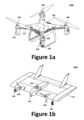
- Figures 1a and 1b illustrate perspective views of example aerial vehicles 100 for use with an adaptive sense and avoid system, namely a multirotor aerial vehicle 100a and a fixed-wing aerial vehicle 100b. More specifically, Figure 1a illustrates an exemplary autonomous multirotor aerial vehicle 100a (illustrated as a quadcopter) capable of vertical take-off and landing, while Figure 1b illustrates a fixed wing aircraft 100b.
- Figure 1a illustrates an exemplary autonomous multirotor aerial vehicle 100a (illustrated as a quadcopter) capable of vertical take-off and landing
- Figure 1b illustrates a fixed wing aircraft 100b.
- the aerial vehicles 100 may comprise an airframe 102 (e.g., a fuselage or chassis), landing gear 104, a flight control system 120 (better illustrated in Figure 1c ), and one or more thrust generators 106 to provide lift or thrust (e.g., a turbine, a motor 108 or engine 118 operatively coupled with a propeller, etc.).
- the flight control system 120 may be housed at least in part within an electronics module, which can be integrated with the airframe 102, provided via a separate housing or pod, or a combination thereof.
- the thrust generators 106 may be coupled to the airframe 102 via a plurality of rotor booms 112.
- one or more fixed wings 114 may be coupled to the airframe 102. While the one or more fixed wings 114 may be distinct from the airframe 102, the fixed wing aircraft 100b may instead be configured as a blended-wing or flying-wing configuration.
- the aerial vehicle 100 may comprise one or more sensors 110 (e.g., as part of an intelligence, surveillance, and reconnaissance (ISR) payload 140 or separately therefrom), such as echolocation sensors, which generally function by emitting a sound frequency into an environment and detecting any echoes of the sound frequency that return from obstacles near the echolocation sensors. Using the strength of the echo and/or direction of echo's return, the echoes may be used to locate and/or identify obstacles, which in turn may cause the aerial vehicle to change direction so as to avoid collision with one or more obstacles.
- ISR intelligence, surveillance, and reconnaissance
- the sensors 110 are not limited to echolocation sensors and may include, inter alia, any vision-based sensor or acoustic sensor known in the art or that will become known in the art, including, without limitation, cameras, radar, LIDAR, and the like.
- cameras may be used to identify larger objects through three-dimensional reconstruction techniques such as optical flow. While this may provide useful information for autonomous navigation, the processing latency associated with optical imaging, as well as the sensitivity to the visibility of various types of objects, may limit the utility of optical sensing techniques for detecting small, rapidly approaching objects in a line of flight of a vehicle. Therefore, echolocation may be used to supplement vision sensing systems.
- the sensors 110 may be positioned to obtain a field of view in the aerial vehicle's direction of travel, thereby identifying potential obstacles in the aerial vehicle 100's path.
- a single sensor 110 (or single group of sensors 110) may be provided at the front of the aerial vehicle 100 to detect a threat of collision (e.g., obstructions or obstacles) in the path of the aerial vehicle 100.
- a threat of collision e.g., obstructions or obstacles
- acoustic detection may supplement optical detection and be used for detecting immediate obstructions that should trigger the execution of responsive maneuvers by a vehicle. While acoustic detection is provided as an example, interactions from virtually any kind of sensor may be used or blended.
- a plurality of sensors 110 may be positioned around the perimeter (and/or top and bottom) of the aerial vehicle 100 to provide a field of view that is oriented with the aerial vehicle 100's line of flight, as well as above and below the aerial vehicle 100, such that the plurality of sensors cover the environment surrounding the aerial vehicle 100. Accordingly, the plurality of sensors 110 would enable the aerial vehicle 100 to detect a threat of collision on any side of the aerial vehicle 100, effectively providing a 360 degree field of view around the aerial vehicle 100.
- an objective of the acoustic sensors is to provide immediate detection of obstacles directly in a flight path (or other line of travel), particularly obstacles that might not be detected using visual detection or other techniques.
- an objective of the sensors 110 is to provide immediate detection of obstacles in a specific direction (e.g., any direction of the aerial vehicle), particularly obstacles that might not be readily detected using visual detection or other techniques.
- an echolocation array operates well, other sensor systems may also, or instead, be suitably employed for rapid, accurate detection of obstacles, such as laser-based techniques or any other suitable techniques using optical, acoustic, radio frequency, or other sensing modalities.
- the adaptive sense and avoid system may employ a combination of vision- and acoustic-based sensors, as well as radar-based or LIDAR systems.
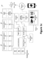
- Figure 1c illustrates a block diagram of an example flight control system 120 for the aerial vehicle 100.
- the flight control system 120 may be configured to control the various components and functions of the aerial vehicle 100.
- the flight control system 120 includes one or more aircraft processors 124 communicatively coupled with at least one memory device 128, a flight controller 126, a wireless transceiver 130, and a navigation system 142.
- the aircraft processor 124 may be configured to perform one or more operations based at least in part on instructions (e.g., software) and one or more databases stored to the memory device 128 (e.g., hard drive, flash memory, or the like).
- the aircraft control system may further include other desired services, such as a wireless transceiver 130 coupled with an antenna 132 to communicate data between the flight control system 120 and a remote device 138 (e.g., a portable electronic devices, such as smartphones, tablets, laptop computers) or other controller (e.g., at a base station).
- a wireless transceiver 130 coupled with an antenna 132 to communicate data between the flight control system 120 and a remote device 138 (e.g., a portable electronic devices, such as smartphones, tablets, laptop computers) or other controller (e.g., at a base station).
- the flight control system 120 may also communicate with another aerial vehicle 100 via the wireless transceiver 130, thereby facilitating collaborative operations, for example.
- the flight control system 120 may communicate data (processed data, unprocessed data, etc.) with the remote device 138 and/or another aerial vehicle 100 over a network 134.
- the wireless transceiver 130 may be configured to communicate using one or more wireless standards such as longer-range links, C-band, Ku/Ka-band, Ultra-High Frequency (UHF) radio waves in the Industrial, Scientific, and Medical (ISM) band from 2.4 to 2.485 GHz), Wi-Fi (e.g., Institute of Electrical and Electronics Engineers' (IEEE) 802.11 standards), etc.
- the remote device 138 may facilitate monitoring and/or control of the flight control system 120 and its payload(s), including an ISR payload 140.
- the remote device 138 provides a control and communication interface for the user.
- the remote device 138 may be configurable to operate as a manager that enables the user to monitor, direct, and control the ASA system 200.
- the remote device 138 can be used to enable a user to input tasks, constraints, revise task assignment lists, update software/firmware, etc.
- the remote device 138 may include a touch screen graphical user interface ("GUI") and/or speech-recognition systems.
- GUI graphical user interface
- the remote device 138 may employ, for example, a tablet computer, a laptop computer, a smart phone, or combination thereof.
- the remote device 138 serves as a primary channel of communication between the pilot and the ASA system 200, enabling the user to, where desired, command tasks to and receive feedback or instructions from the ASA system 200.
- the remote device 138 may give visual and auditory alerts to direct the pilot's attention to a particular alert.
- the aircraft processor 124 may be operatively coupled to the flight controller 126 to control operation of the various actuators (e.g. , those to control movement and locking of any flight surfaces, such as the moveable flight control surfaces, electric motor 108 ( e.g., via an electronic speed controller (ESC) 116), and/or engines 118 ( e.g., via an engine controller 122) in response to commands from an operator, autopilot, a navigation system 142, or other high-level system via the wireless transceiver 130.
- the aircraft processor 124 and the flight controller 126 may be integrated into a single component or circuit.
- the flight controller 126 may dynamically (i.e., in real-time or near real-time) and independently adjust one or more moveable flight control surfaces and/or thrust from the thrust generators 106 during the various stages of flight ( e.g., via the ESC 116 or engine controller 122 (as the case may be)) to control roll, pitch, or yaw of the aerial vehicle 100.
- the flight controller 126 may vary the revolutions per minute (RPM) of the rotor and/or, where desired, vary the pitch of the rotor blades.
- the electric motors 108 may be controlled by adjusting power supplied to each electric motor from a power supply (e.g., a battery pack or a battery bank) via the ESC 116.
- the aircraft processor 124 may be operatively coupled to the navigation system 142, which may include the GPS 142a that is communicatively coupled with the INS 142b and/or the IMU 142c, which can include one or more gyros and accelerometers.
- the GPS 142a gives an absolute drift-free position value that can be used to reset the INS solution or can be blended with it by use of a mathematical algorithm, such as a Kalman Filter.
- the navigation system 142 may communicate, inter alia, inertial stabilization data to the aircraft processor 124.
- the flight control system 120 may be equipped with additional sensors 110, such as an ISR payload 140 comprising, for example, one or more cameras 140a (e.g., an optical instrument for recording or capturing images and/or video, including light detection and ranging (LiDAR) devices), audio devices 140b (e.g., microphones, echolocation sensors, etc.), and other sensors 140c to facilitated ISR functionality and provide ISR data (e.g. , photographs, video, audio, sensor measurements, etc.).
- the ISR payload 140 is operatively coupled to the aircraft processor 124 to facilitate communication of the ISR data (sensor data) between the ISR payload 140 and the aircraft processor 124.
- the ISR data may be used to navigate the aerial vehicle 100 and/or otherwise control the flight control system 120.
- the ISR payload 140 may be rotatably and pivotally coupled to, for example, the underside surface of the airframe 102 (or another structural component, such as the rotor booms 112 or the wings 114) via a gimbal system to enable the ISR payload 140 to be more easily oriented downward to monitor objects below and/or on the ground.
- the data may be dynamically or periodically communicated from the flight control system 120 to the remote device 138 over the network 134 via the wireless transceiver 130, or stored to the memory device 128 for later access or processing.
- the below-described ASA system 200 may be integrated with the flight control system 120 such that it uses preexisting hardware, including, for example, the aircraft processor 124, memory device 128, flight controller 126, and sensors 110.
- the features and processes of the ASA system 200 may be implemented in the aircraft 100 through a software and/or firmware update (e.g ., to the memory device 128 via the remote device 138).
- the ASA system 200 may be couple to the aircraft 100 as a module that is communicatively coupled with the flight control system 120 ( e.g. , via the aircraft processor 124, as illustrated in Figure 1c ).
- FIGS 2a through 2c illustrate an adaptive sense and avoid (ASA) system 200 for the automatic detection and avoidance of obstacles (e.g. , other air traffic, structures, natural formations, animals, etc.) to be utilized on an aircraft 100.
- the ASA system 200 fuses sensors (e.g. , dynamically - in real-time or near real-time) as a function of the altitude, geographic area, and/or airspace in which the aircraft 100 is flying.
- the ASA system 200 may be configured to pass warning alerts and status to any ground operator or supervisor through an existing datalink (e.g. , to a remote device 138 over network 136) on the UAV aircraft 100.
- the ASA system 200 endeavors to detect cooperative and/or non-cooperative obstacles and to command an automatic avoidance maneuver to avoid a collision with the obstacle and/or other obstacles.
- the ASA system 200 cross-correlates and blends multiple obstacle sensors to develop the most accurate estimation of the position(s) and type(s) of obstacle(s) in an environment.
- the ASA system 200 offers a number of advantages. For example, in addition to altitude, geographic area, and/or airspace, the ASA system 200 may further adapt the fusion of sensors as a function of the time of day, current weather, and season of the year. There may be multiple areas of fusion, such as weighting of the different sensors for refining obstacle position relative to the host aircraft, and any assigning priority for alerting or avoidance maneuvers. For instance, depending on current location (airspace type), an obstacle detection radar might be given a higher priority for obstacle detection, while visual sensors neglected. In another example, when operating inside an airport terminal area, cooperative sensors (e.g. , ADS-B data) could be given a highest priority for weighting, with less priority on visual sensors.
- ADS-B data cooperative sensors
- sensors for such obstacles will be given priority (such as visual sensors or small radar.) Sensors capable of detecting hazardous bird obstacles would also be given higher priority when operating in locations and times of the day or times of the year when bird activity is expected to be high.
- the aircraft 100 may perform automatic obstacle avoidance maneuvers to account for local terrain conditions, which can avoid potential collisions with terrain while avoiding obstacles. Therefore, the ASA system 200 may employ a model of aircraft performance, which can be used to determine possible collision-avoidance trajectories that will be successful.
- the ASA system 200 may also take into account weather conditions when calculating obstacle avoidance maneuvers. For example, the ASA system 200 may account for ambient winds or density altitude when determining optimal trajectories, and avoiding weather hazards in the immediate vicinity.
- the ASA system 200 may generally comprise an obstacle detection circuit 202, an avoidance maneuver trajectory circuit 204, one or more databases 224, and obstacle sensors 226 (e.g., one or more sensors 110) to generate lists of possible obstacle threats.
- the ASA system 200 may be operatively coupled with (or integrated with) the flight control system 120 of the aircraft 100. Accordingly, the obstacle detection circuit 202 and/or the avoidance maneuver trajectory circuit 204 may receive positional data from an external GPS or an integrated (internal) GPS (e.g., GPS 142a) and/or aircraft state data (e.g., altitude, speed, ⁇ altitude, etc.) from the aircraft data system 228.
- GPS e.g., GPS 142a
- aircraft state data e.g., altitude, speed, ⁇ altitude, etc.
- the ASA system 200 may receive aircraft state information (e.g. , altitude, rate of climb, pitch angle, bank angle, yaw angle, sideslip, etc.) from an aircraft data system 228, which may be integrated with the aircraft 100 ( e.g., as part of the flight control system 120).
- aircraft data system 228 may comprise, for example, a gyro and/or other state sensors.
- the ASA system 200 can issue trajectory commands to the onboard flight control system 120 of the aircraft 100, which may cause (instruct) the aircraft 100 to execute an avoidance trajectory (or flight path).
- the avoidance trajectory may be calculated in real-time based at least in part on sensor data from the sensors 110, ISR payload 140, etc.
- the ASA system 200 can also pass warning alerts and status information to any ground operator or supervisor via, for example, a remote device 138 at a ground control station (GCS) 230 through an existing datalink on the aircraft 100, such as network 136. More specifically, the obstacle detection circuit 202 may send obstacle alerts to the GCS 230, while the avoidance maneuver trajectory circuit 204 may send avoidance maneuver information to the GCS 230.
- GCS ground control station
- the plurality of obstacle sensors 226 may comprise, for example, cooperative obstacle sensors 226a to detect cooperative obstacle (e.g. , another aircraft having a cooperative transmitter or transceiver) and/or non-cooperative obstacle sensors 226b to detect non-cooperative obstacle.
- the cooperative obstacle sensors 226a may be used to detect obstacles ( e.g ., other air traffic) using, for example, a radio-frequency transceiver configured to communicated using one or more of various protocols, including ADS-B, TCAS, TAS, etc.
- the non-cooperative obstacle sensors 226b may detect obstacles ( e.g. , other air traffic) using, for example, radar-based systems, electro-optical systems (e.g.
- the obstacle sensors 226 may assign a threat level (priority level) to one or more (or all) of possible obstacle threats, in other cases they may not; instead only providing location information for the other obstacles.
- location information may include GPS coordinates or angle and distance.
- Obstacle information from the obstacle sensors 226 may also include velocity of the target obstacle and/or information on the type or identity of the obstacles (e.g., aircraft, tail number, bird, size, etc.).
- the type of sensors 110 used as the obstacle sensors 226 may depend on the type and size of aircraft 100 being considered and the operating environment of that aircraft 100.
- the one or more databases 224 which may be stored to memory device 128, can be used to identify any flight constraints imparted upon the aircraft 100.
- the one or more databases 224 may comprise, for example, an airspace database 224a, an environment database 224b, a terrain database 224c, etc.
- the one or more databases 224 may cover a larger area than expected for current operations of the aircraft 100; however the one or more databases 224 may be limited to a specific area/environment if desired.
- the ASA system 200 may update the one or more databases 224 dynamically to reflect the most current data available, which may be captured by the obstacle sensors 226 or another sensor 110.
- the one or more databases 224 (in connection with the obstacle sensors 226 and any other sensors 110) support the obstacle detection circuit 202 for calculating obstacle threats. Once a threat has been detected, the one or more databases 224 support the avoidance maneuver trajectory circuit 204, by providing information on airspace, terrain, and/or environmental factors that affect the trajectory.
- the airspace database 224a may comprise airspace data reflecting airspace and aeronautical features.
- the airspace database 224a holds detailed data on all types of defined legal airspace in the area of operations including, without limitation: control zones, traffic management areas, en route airspace, restricted areas, prohibited areas, temporary flight restrictions, military operating areas, etc. Further, data reflecting established airways and approach procedures may also be included.
- the environment database 224b may comprise environment data reflecting environmental factors, including current and expected weather, local effects of time of day or time of year, etc.
- the environmental database 224b may include, without limitation, obstacle data, expected climate data, current and pending weather data, and human activity data (expected events or activity in a given area in a given time period).
- the terrain database 224c may comprise terrain data reflecting terrain clearance, including specific man-made or natural features, such as peaks, antenna towers, buildings, etc., for example.
- the terrain database 224c holds detailed data on the terrain in the area of operations.
- the terrain database 224c may cover a larger area than expected for current operations, or data for specific areas can be loaded as required.
- the terrain database 224c can be updated by the aircraft 100 with the most current data available, for accuracy.
- the obstacle detection circuit 202 can use input from sensors to determine the best estimate of obstacles (e.g. , type, location, trajectory, etc.). Obstacle detection circuit 202 may be used to correlate data ( e.g. , using internal algorithms) from multiple sensors to refine obstacle location, and to determine the threat level of detected obstacles. For example, as illustrated, the obstacle detection circuit 202 may receive sensor state and obstacle information from the cooperative obstacle sensors 226a and/or non-cooperative obstacle sensors 226b. The obstacle detection circuit 202 may also be configured to communicate mode commands 208 to the cooperative obstacle sensors 226a and/or non-cooperative obstacle sensors 226b.
- the mode commands 208 may cause the cooperative obstacle sensors 226a and/or non-cooperative obstacle sensors 226b to change, or otherwise adjust, its mode of operation.
- one or more machine learning techniques may be employed and used to fuse sensor data from different types of sensors based at least in part on historic performance data associated with the aerial vehicle 100 (e.g. , in various situations and environments, such as weather condition, time, location, altitude, etc.). For example, while certain sensors systems may not be ideal in certain environments, historical data may indicate that such sensors systems are nevertheless favorable or useable in certain regions when subject to certain environmental conditions or coupled with other types of sensors.
- the obstacle detection circuit 202 also uses information about vehicle location, compared from the aircraft data system 228 against the one or more databases 224 of geography, airspace, and environmental factors to set weighting of the cooperative obstacle sensors 226a and/or non-cooperative obstacle sensors 226b via the obstacle detection circuit 202.
- the obstacle detection circuit 202 can use airspace data from the airspace database 224a to refine the detection algorithms based on the location of the aircraft 100 in relation to different types of regulated airspace.
- the obstacle detection circuit 202 can use environmental data from the environmental database 224b refine the detection algorithms based on environmental factors such as time of year, day of week, time of day, climate and weather conditions, etc.
- the obstacle detection circuit 202 may output to the avoidance maneuver trajectory circuit 204 a best estimate of obstacles in the form of, for example, obstacle alert information/data.
- the avoidance maneuver trajectory circuit 204 can use internal algorithms to calculate an avoidance maneuver to avoid detected obstacle and terrain based at least in part on the obstacle alert information/data from the obstacle detection circuit 202.
- the avoidance maneuver trajectory circuit 204 is configured to develop an avoidance trajectory to ensure safe separation from obstacle targets, while also accounting for local terrain, airspace, and environmental factors based on data from the one or more databases 224.
- the avoidance maneuver trajectory circuit 204 can use terrain data from the terrain database 224c to ensure avoidance maneuvers are not compromised by local terrain.
- different groupings of the plurality of sensors may be blended and/or selected depending on the current operation (i.e. mission objective) and/or environment of the aerial vehicle 100.
- one or more sensor groupings may be employed, whether automatically or manually selected, based on the surrounding environment.
- the one or more database may store one or more predetermined groupings of sensors to be utilized upon detection of certain environmental conditions, aerial vehicle operation, aerial vehicle health or status, and/or flight constraints imparted upon the aerial vehicle 100.
- Figure 2b illustrates an example process for the obstacle detection circuit 202.
- the subtasks of the obstacle detection circuit 202 may run dynamically to provide the fastest response to potential obstacle threats.
- the obstacle detection circuit's 202 subtasks may include checking current aircraft state and environment 206, setting sensor modes 208, setting obstacle detection weights 210, evaluating incoming obstacle data 212, and transmitting obstacle threat information to the avoidance maneuver trajectory planner 213.
- Example aircraft states include, for example, a current altitude, airspeed, and type of mission
- the obstacle detection circuit 202 also checks current location in relation to airspace and environment. For example, the aircraft's 100 location in relation to defined airspace, its location in relation to ground features (e.g. , urban areas and rural areas), and its location in relation to terrain features such as hills and mountains.
- ground features e.g. , urban areas and rural areas
- terrain features such as hills and mountains.
- the obstacle detection circuit 202 may also set any sensor modes 208 as necessary, which may be as a function of the current aircraft state and environment.
- the obstacle detection circuit 202 can send mode commands to the obstacle sensors 226 to set particular sensor modes as a function of the current aircraft state and environment. For instance, when the aircraft 100 is in a transiting mission, obstacle sensors 226 may be directed to a mode that emphasizes the area in front of the aircraft, while if the aircraft is in a loitering mission, sensor modes that examine 360 degrees around the aircraft 100 would be selected. In another example, if operating at a low level, a radar sensor may be commanded to a mode that does more to reject ground clutter in the radar signal.
- the obstacle detection circuit 202 can also set obstacle detection weights 210 based on current state and environment, as well as currently-active sensors 226. Based on the environmental factors described above, the obstacle detection circuit 202 sets weighting factors for evaluating the obstacle data coming from the sensors. For instance if current weather conditions include poor visibility, data from a radar sensor may be given a greater weight than data from a vision-based sensor. In another case, when flying in controlled airspace where other obstacles would be expected to be equipped with cooperative systems, such cooperative obstacle sensors would be given higher weights than non-cooperative obstacle sensors like vision systems. The exact degree or level of weighting can be determined through a combination of analysis, simulation, and collection of empirical data.
- the obstacle detection circuit 202 can evaluate incoming obstacle data 212 using, for example, weighted sensor values. In other words, with the obstacle detection weights already set, the obstacle detection circuit 202 evaluates the incoming obstacle data. Where multiple sensors 226 detect the same obstacle, the obstacle detection circuit 202 can use the obstacle detection weights to cross-check and refine the relative position of the obstacle. For instance, if a radar sensor and a vision sensor both detect what appears to be an obstacle, but the reported relative positions are slightly off, if the radar sensor has a higher weighting than the vision sensor, then the actual position of the obstacle will be assumed to be closer to the data reported by the radar sensor. Since the obstacle detection weights are based on changing aircraft and environment factors, the action of the obstacle detection circuit 202 may also change as the weighting factors between sensors may change as a function of the aircraft and environmental factors.
- the obstacle detection circuit 202 can communicate obstacle threat information (e.g. , obstacle position and state) 213 to the avoidance maneuver trajectory circuit 204.
- the obstacle detection circuit 202 can share the obstacle threat information dynamically (e.g. , in real-time or near real-time) with the avoidance maneuver trajectory circuit 204.
- the obstacle detection circuit 202 may be configured to share not only the highest-priority obstacle targets, but also other detected obstacles to provide a complete picture of the obstacle(s) in the area to the avoidance maneuver trajectory circuit 204.
- the obstacle detection circuit 202 may use advanced logic such as machine learning to refine the ability to detect obstacles while minimizing false positive detections. Such machine learning may build and then use a database of information gathered on previous flights. Such a database may include a hot spot of geographic areas or temporal or environmental factors where other obstacles (e.g ., air traffic) are often detected, or conversely areas where false positives are likely for environmental or other reasons.
- the system is capable of avoiding potentially hazardous situations.
- information collected from the various sensors can be compiled and analyzed as a whole, in view of stored data including historical trends, to quickly and accurately build a picture of an aerial vehicle's expected and/or common reaction to a variable.
- the system may be configured to accept, analyze, and/or make determinations based at least in part on the various sensor information, or "sensor fusion", among sensors of differing types, such as optical sensors, physiological sensors, vehicle state sensors, to name but a few.
- machine learning/deep learning techniques capable of collecting data and building models over time to recognize and adapt to similar situations in the future, are used to overcome limited views, damaged identifiers, variable lighting conditions, to name a few.
- the machine learning technique may be utilized to update the logic of determining the selection of a group of the various sensors in certain environmental conditions by analyzing the effectiveness of the selected group in various environmental conditions.
- the avoidance maneuver trajectory circuit 204 evaluates the obstacle threats reported by the obstacle detection circuit 202 and plans avoidance maneuver(s) to avoid conflicts or collisions.
- Figure 2c illustrates subtasks of an avoidance maneuver trajectory circuit 204.
- the avoidance maneuver trajectory circuit's 204 subtasks may include monitoring aircraft location and state 214, querying databases 216, calculating a trajectory 218, calculating an avoidance maneuver 220, and issuing commands 222 to the flight control system 120.
- the avoidance maneuver trajectory circuit 204 monitors aircraft location and state dynamically 214, which may be received from the GPS 142a and/or the aircraft data system 228, for example.
- the avoidance maneuver trajectory circuit 204 queries databases 216, such as the one or more databases 224. More specifically, based at least in part on the current location and state of the aircraft 100, the avoidance maneuver trajectory circuit 204 queries the airspace, terrain, and environment databases 224a, 224b, 224c for data relevant to the current location and state.
- the avoidance maneuver trajectory circuit 204 may calculate a trajectory 218. More specifically, the avoidance maneuver trajectory circuit 204 can calculate trajectories continuously that are clear of terrain and accounts for airspace and other factors, even without the presence of traffic obstacles. These default trajectories can define safe zones, where the ASA system 200 knows the aircraft 100 will not conflict with terrain or airspace.
- the avoidance maneuver trajectory circuit 204 may also calculate an avoidance maneuver 220. That is, when information on potentially dangerous obstacles is received from the obstacle detection circuit 202, the avoidance maneuver trajectory circuit 204 can immediately calculate a flightpath trajectory to avoid the traffic obstacle(s), while also considering other nearby traffic, terrain, obstacles, and nearby airspace based on data from the one or more databases 224. For instance, if the ASA system 200 has possible avoidance trajectories either to the right or left, but the data that the avoidance maneuver trajectory circuit 204 has shown that there is conflicting terrain or restricted airspace to the right of the aircraft 100, then the avoidance maneuver trajectory circuit 204 will plan an avoidance trajectory to the left side instead. Therefore, when an obstacle threat report from the obstacle detection circuit 202 is received, the avoidance maneuver trajectory circuit 204 recalculates a trajectory to avoid the obstacle, while also avoiding terrain, accounting for airspace, and operating within a/c performance envelope.
- the avoidance maneuver trajectory circuit 204 issues the resulting commands 222 to flight control system 120 to execute the avoidance maneuver.
- the resulting commands may be, for example, a commanded waypoint or speed, heading, altitude commands.
- Figure 3 illustrates an example navigational method 300 for operating an aircraft 100 equipped with an ASA system 200.
- the aircraft 100 is performing a loitering mission at a relatively low level in an environment with a mountainous terrain.
- the ASA system 200 determines the state of the aircraft 100 and the surrounding environment at step 304.
- the obstacle detection circuit 202 evaluates the location to identify and/or locate the mountains.
- the obstacle detection circuit 202 may also determine that the current time of year is summer based on, for example, the location ( e.g. , via GPS data) and an internal calendar, which may be supplemented/confirmed using one or more sensors (e.g. , thermometers, light sensors, barometers, etc.).
- the one or more sensors may also be used to determine the current weather.
- the obstacle detection circuit 202 may set the sensor modes for each of the obstacle sensors 226 at step 306.
- the obstacle detection circuit 202 may command both the vision-based sensor and a radar sensor to be in 360-degree mode, thereby looking for obstacles on all sides of the aircraft 100.
- the obstacle detection circuit 202 may assign weights to the various sensors 110 (e.g. , obstacle sensors 226). For example, if the weather is clear (e.g. , high visibility), the ASA system 200 may set obstacle detection weights that favor the sensor data from vision-based obstacle sensors, since hard-to-detect non-cooperative obstacles such as paragliders might be expected under these conditions.
- the ASA system 200 evaluates sensor data captured from the obstacle sensors 226. Although it is possible to detect an obstacle using multiple sensors (e.g. , both the vision and radar sensors), where the weighting factor favors the vision-based system, the vision-based system is given preference (or priority) when evaluating the sensor data from both sensors.
- the obstacle detection circuit 202 generates threat information and reports the data reflecting the detected obstacles to the avoidance maneuver trajectory circuit 204.
- the avoidance maneuver trajectory circuit 204 dynamically monitors the location and state of the aircraft 100 in the environment. In additional to monitoring sensor data, the avoidance maneuver trajectory circuit 204 queries at step 316 one or more databases 224, which may identify, for example, nearby mountainous terrain, restricted airspace, etc.
- the ASA system 200 evaluates the potential avoidance maneuvers and calculates a trajectory command for the aircraft.
- the trajectory command is communicated as a command to the flight control system 120 of the aircraft 100 to complete the maneuver. If the mission is complete at step 322, the 300 may end at step 324. Otherwise, the navigational method 300 returns to step 304, where the process repeats.
- navigational method 300 is illustrated as an example having a particular combination of steps, one of skill in the art would appreciate that fewer or additional steps may be implemented. In certain aspects, one or more steps may be performed in parallel. Further, one or more steps may be optional and omitted from the navigational method 300, or performed separately and/or upon request from an operator. In some aspects, one or more steps may be conditional, such that execution of the one or more steps may be contingent upon predetermined requirements and/or conditions. Moreover, the order in which the steps are cycled may be rearranged depending on the needs of the operator or the system.
- ASA system 200 is described having certain features, other extra features can be considered optional, and could be added or subtracted as software upgrades, depending on user needs and budget. For instance, system adjustments may be based only on airspace or geography, without including adjustments for time of year or time of day. This could be added as an upgrade on a cost basis.
- Another variation could be the system installed in a piloted aircraft, as a complementary obstacle detection system, still using the situation-based blending of sensor data to give obstacle alerts and recommended avoidance trajectories to a human pilot.
- the avoidance maneuver trajectory circuit 204 may include additional logic to account for balancing avoidance maneuvers against passenger comfort and safety, to be used for pilot-less autonomous aircraft carrying passengers, or could also be used in the variation described above for piloted aircraft.
- This variation would balance obstacle threat level and the maneuvers required to avoid the obstacle, against passenger comfort factors such as accelerations and jerk (change in acceleration).
- the ASA system 200 may be employed in military, government, and civilian applications. Though, the ASA system 200 is particularly useful for aircraft 100 with a wide range of operating altitudes and airspace types, such as tactical- or MALE-class aircraft 100.
Landscapes
- Engineering & Computer Science (AREA)
- Physics & Mathematics (AREA)
- General Physics & Mathematics (AREA)
- Aviation & Aerospace Engineering (AREA)
- Radar, Positioning & Navigation (AREA)
- Remote Sensing (AREA)
- Automation & Control Theory (AREA)
- Multimedia (AREA)
- Theoretical Computer Science (AREA)
- Business, Economics & Management (AREA)
- Health & Medical Sciences (AREA)
- Artificial Intelligence (AREA)
- Evolutionary Computation (AREA)
- Game Theory and Decision Science (AREA)
- Medical Informatics (AREA)
- Computer Networks & Wireless Communication (AREA)
- Electromagnetism (AREA)
- Traffic Control Systems (AREA)
- Control Of Position, Course, Altitude, Or Attitude Of Moving Bodies (AREA)
Applications Claiming Priority (2)
| Application Number | Priority Date | Filing Date | Title |
|---|---|---|---|
| US16/159,397 US11037453B2 (en) | 2018-10-12 | 2018-10-12 | Adaptive sense and avoid system |
| EP19202812.4A EP3640921B1 (en) | 2018-10-12 | 2019-10-11 | Adaptive sense and avoid system |
Related Parent Applications (1)
| Application Number | Title | Priority Date | Filing Date |
|---|---|---|---|
| EP19202812.4A Division EP3640921B1 (en) | 2018-10-12 | 2019-10-11 | Adaptive sense and avoid system |
Publications (1)
| Publication Number | Publication Date |
|---|---|
| EP4235626A1 true EP4235626A1 (en) | 2023-08-30 |
Family
ID=68318779
Family Applications (2)
| Application Number | Title | Priority Date | Filing Date |
|---|---|---|---|
| EP23173179.5A Pending EP4235626A1 (en) | 2018-10-12 | 2019-10-11 | Adaptive sense and avoid system |
| EP19202812.4A Active EP3640921B1 (en) | 2018-10-12 | 2019-10-11 | Adaptive sense and avoid system |
Family Applications After (1)
| Application Number | Title | Priority Date | Filing Date |
|---|---|---|---|
| EP19202812.4A Active EP3640921B1 (en) | 2018-10-12 | 2019-10-11 | Adaptive sense and avoid system |
Country Status (7)
| Country | Link |
|---|---|
| US (2) | US11037453B2 (enExample) |
| EP (2) | EP4235626A1 (enExample) |
| JP (1) | JP7606812B2 (enExample) |
| KR (1) | KR102837990B1 (enExample) |
| CN (1) | CN111045444B (enExample) |
| AU (1) | AU2019208250B2 (enExample) |
| CA (1) | CA3050426C (enExample) |
Families Citing this family (29)
| Publication number | Priority date | Publication date | Assignee | Title |
|---|---|---|---|---|
| US11037453B2 (en) * | 2018-10-12 | 2021-06-15 | Aurora Flight Sciences Corporation | Adaptive sense and avoid system |
| US11521500B1 (en) * | 2018-10-17 | 2022-12-06 | Amazon Technologies, Inc. | Unmanned aerial systems with range finding |
| PL3887854T3 (pl) * | 2018-11-27 | 2023-03-20 | Leonardo S.P.A. | Układ kontroli ruchu przestrzeni suborbitalnej |
| US11003195B2 (en) * | 2019-02-28 | 2021-05-11 | GM Global Technology Operations LLC | Method to prioritize the process of receiving for cooperative sensor sharing objects |
| US11458997B2 (en) | 2020-03-31 | 2022-10-04 | Uatc, Llc | Autonomous vehicle computing system with processing assurance |
| US11988742B2 (en) | 2020-04-07 | 2024-05-21 | MightyFly Inc. | Detect and avoid system and method for aerial vehicles |
| US20210325906A1 (en) * | 2020-04-17 | 2021-10-21 | Here Global B.V. | Method and apparatus for determining navigation routes based on environmental quality data |
| CN111505623B (zh) * | 2020-04-24 | 2023-04-18 | 中南大学 | 无人驾驶车辆行驶过程中的障碍物检测方法、系统、车辆 |
| JP7402121B2 (ja) * | 2020-06-02 | 2023-12-20 | 株式会社日立製作所 | 物体検出システムおよび物体検出方法 |
| ES3013318T3 (en) * | 2020-09-25 | 2025-04-11 | Ruag Schweiz Ag | Method to navigate an unmanned aerial vehicle to avoid collisions |
| US11763555B2 (en) * | 2021-04-22 | 2023-09-19 | Honeywell International Inc. | System and method for ground obstacle detection and database management |
| EP4080482B1 (en) * | 2021-04-22 | 2025-08-20 | Honeywell International Inc. | System and method for obstacle detection and database management |
| US12046041B2 (en) * | 2021-05-25 | 2024-07-23 | Motorola Solutions, Inc. | Flight guidance and control interfaces for unmanned air vehicles |
| US12065240B2 (en) * | 2021-09-08 | 2024-08-20 | Ge Aviation Systems Llc | Systems and methods for airspace management |
| CN114442664B (zh) * | 2022-01-17 | 2023-09-26 | 江苏方天电力技术有限公司 | 一种计及空域冲突的输电线路无人机编队协同巡检任务分配方法 |
| WO2023150287A1 (en) * | 2022-02-04 | 2023-08-10 | Zipline International Inc. | Tactical deconfliction system for unmanned aerial vehicles |
| US20250189979A1 (en) * | 2022-03-29 | 2025-06-12 | Sony Group Corporation | Data processing method, data processing device, program, and moving body control system |
| CN116931593A (zh) * | 2022-04-07 | 2023-10-24 | 广东汇天航空航天科技有限公司 | 飞行控制方法、装置、飞行器及存储介质 |
| JP2025516295A (ja) * | 2022-05-04 | 2025-05-27 | イノベイティブ・ソリューションズ・アンド・サポート・インコーポレイテッド | 自動飛行追従オプションを実装し、旧来の飛行管理システムをアップグレードするためのシステムおよび方法 |
| CN115016515B (zh) * | 2022-06-06 | 2024-08-23 | 重庆交通职业学院 | 无人机用障碍物探测预警系统 |
| US12234013B2 (en) * | 2022-06-21 | 2025-02-25 | Here Global B.V. | Method and apparatus for determining navigation routes based on weather manipulation data |
| CN115079726B (zh) * | 2022-08-09 | 2025-11-04 | 上海沃兰特航空技术有限责任公司 | 飞行障碍探测避让方法、装置、电子设备以及存储介质 |
| CN115862389B (zh) * | 2022-11-18 | 2025-04-08 | 中国航空无线电电子研究所 | 一种机载防撞系统的架构 |
| CN116597696A (zh) * | 2023-05-17 | 2023-08-15 | 深圳市喜悦智慧数据有限公司 | 基于多样环境因素的低空飞行器避撞预警系统及其方法 |
| CN119085623A (zh) * | 2023-06-05 | 2024-12-06 | 空客(北京)工程技术中心有限公司 | 飞行器地面防碰撞系统及方法 |
| CN116803813B (zh) * | 2023-08-22 | 2023-11-10 | 腾讯科技(深圳)有限公司 | 障碍物行驶轨迹预测方法、装置、电子设备及存储介质 |
| JP7407329B1 (ja) | 2023-10-04 | 2023-12-28 | 株式会社インターネットイニシアティブ | 飛行誘導装置および飛行誘導方法 |
| CN117406729B (zh) * | 2023-10-19 | 2024-10-22 | 中国民航大学 | 一种evtol避让系统的rta设计方法、设备及介质 |
| KR20250107032A (ko) * | 2024-01-04 | 2025-07-11 | 현대자동차주식회사 | 비행 모빌리티의 제어 장치 및 방법 |
Citations (7)
| Publication number | Priority date | Publication date | Assignee | Title |
|---|---|---|---|---|
| US20100039310A1 (en) * | 2007-05-02 | 2010-02-18 | Smith Mark D | Systems and methods for air traffic surveillance |
| US20110118980A1 (en) * | 2009-11-13 | 2011-05-19 | The Boeing Company | Lateral Avoidance Maneuver Solver |
| US20160266256A1 (en) * | 2015-03-11 | 2016-09-15 | The Boeing Company | Real Time Multi Dimensional Image Fusing |
| US20170045886A1 (en) * | 2014-09-05 | 2017-02-16 | SZ DJI Technology Co., Ltd | Context-based flight mode selection |
| US20170345321A1 (en) * | 2014-11-05 | 2017-11-30 | Sierra Nevada Corporation | Systems and methods for generating improved environmental displays for vehicles |
| US20180032040A1 (en) * | 2016-08-01 | 2018-02-01 | Qualcomm Incorporated | System And Method Of Dynamically Controlling Parameters For Processing Sensor Output Data For Collision Avoidance And Path Planning |
| JP2018144772A (ja) * | 2017-03-09 | 2018-09-20 | 株式会社Soken | 飛行装置 |
Family Cites Families (139)
| Publication number | Priority date | Publication date | Assignee | Title |
|---|---|---|---|---|
| US4063073A (en) | 1974-11-29 | 1977-12-13 | Strayer Larry G | Computer system to prevent collision between moving objects such as aircraft moving from one sector to another |
| US5157615A (en) | 1990-01-09 | 1992-10-20 | Ryan International Corporation | Aircraft traffic alert and collision avoidance device |
| JPH07115677B2 (ja) | 1990-10-30 | 1995-12-13 | 嘉三 藤本 | 航空機の飛行情報記録方法とその装置 |
| US5654890A (en) | 1994-05-31 | 1997-08-05 | Lockheed Martin | High resolution autonomous precision approach and landing system |
| US5557278A (en) * | 1995-06-23 | 1996-09-17 | Northrop Grumman Corporation | Airport integrated hazard response apparatus |
| US5781146A (en) | 1996-03-11 | 1998-07-14 | Imaging Accessories, Inc. | Automatic horizontal and vertical scanning radar with terrain display |
| GB2320829B (en) | 1996-12-04 | 1998-10-21 | Lockheed Martin Tactical Sys | Method and system for predicting the motion e.g. of a ship or the like |
| JP3038166B2 (ja) * | 1997-07-02 | 2000-05-08 | 川崎重工業株式会社 | 航空機搭載用障害物探知装置 |
| US6268803B1 (en) | 1998-08-06 | 2001-07-31 | Altra Technologies Incorporated | System and method of avoiding collisions |
| US20020100838A1 (en) | 1999-06-08 | 2002-08-01 | Mcgeer Brian T. | Method and apparatus for retrieving a flying object |
| EP1252060B1 (en) | 2000-02-03 | 2005-11-16 | Honeywell International Inc. | Event based aircraft image and data recording system |
| US6870792B2 (en) | 2000-04-04 | 2005-03-22 | Irobot Corporation | Sonar Scanner |
| US6480152B2 (en) | 2000-07-20 | 2002-11-12 | American Gnc Corporation | Integrated GPS/IMU method and microsystem thereof |
| DE60107692T2 (de) | 2000-08-16 | 2005-12-15 | Raytheon Company, Waltham | System zur erfassung von naheliegenden objekten |
| US6480789B2 (en) * | 2000-12-04 | 2002-11-12 | American Gnc Corporation | Positioning and proximity warning method and system thereof for vehicle |
| FR2821452B1 (fr) | 2001-02-26 | 2003-06-13 | Eads Airbus Sa | Dispositif de surveillance d'une pluralite de systemes d'un aeronef, en particulier d'un avion de transport |
| US6804607B1 (en) | 2001-04-17 | 2004-10-12 | Derek Wood | Collision avoidance system and method utilizing variable surveillance envelope |
| US7203620B2 (en) | 2001-07-03 | 2007-04-10 | Sharp Laboratories Of America, Inc. | Summarization of video content |
| US6678210B2 (en) | 2001-08-28 | 2004-01-13 | Rowe-Deines Instruments, Inc. | Frequency division beamforming for sonar arrays |
| US6665063B2 (en) | 2001-09-04 | 2003-12-16 | Rosemount Aerospace Inc. | Distributed laser obstacle awareness system |
| US6604044B1 (en) | 2002-02-14 | 2003-08-05 | The Mitre Corporation | Method for generating conflict resolutions for air traffic control of free flight operations |
| EP1340999A1 (en) | 2002-02-28 | 2003-09-03 | Alignment International Limited | Method and apparatus for identifying the position of an object |
| US6820006B2 (en) | 2002-07-30 | 2004-11-16 | The Aerospace Corporation | Vehicular trajectory collision conflict prediction method |
| US7725258B2 (en) | 2002-09-20 | 2010-05-25 | M7 Visual Intelligence, L.P. | Vehicle based data collection and processing system and imaging sensor system and methods thereof |
| EP1563616B1 (en) | 2002-11-11 | 2011-11-02 | Aeromechanical Services Ltd | Aircraft flight data management system and corresponding method |
| US6960750B2 (en) | 2003-01-08 | 2005-11-01 | The Boeing Company | Optical positioning system and method, transceiver, and reflector |
| US7059564B2 (en) | 2003-01-17 | 2006-06-13 | The Insitu Group, Inc. | Methods and apparatuses for capturing and recovering unmanned aircraft, including a cleat for capturing aircraft on a line |
| US6975246B1 (en) | 2003-05-13 | 2005-12-13 | Itt Manufacturing Enterprises, Inc. | Collision avoidance using limited range gated video |
| NO333526B1 (no) | 2003-06-12 | 2013-07-01 | Vestas Wind Sys As | System for å avverge kollisjon mellom luftfartøy og et hinder |
| US7343232B2 (en) | 2003-06-20 | 2008-03-11 | Geneva Aerospace | Vehicle control system including related methods and components |
| US7061401B2 (en) | 2003-08-07 | 2006-06-13 | BODENSEEWERK GERäTETECHNIK GMBH | Method and apparatus for detecting a flight obstacle |
| US7443154B1 (en) | 2003-10-04 | 2008-10-28 | Seektech, Inc. | Multi-sensor mapping omnidirectional sonde and line locator |
| US7106219B2 (en) | 2003-11-07 | 2006-09-12 | Pearce James W | Decentralized vehicular traffic status system |
| US7194358B2 (en) | 2004-02-25 | 2007-03-20 | The Boeing Company | Lift collision avoidance system |
| US7193729B1 (en) | 2004-04-29 | 2007-03-20 | Yazaki North America, Inc | Instrument cluster with laser beam illumination |
| WO2005125267A2 (en) | 2004-05-05 | 2005-12-29 | Southwest Research Institute | Airborne collection of acoustic data using an unmanned aerial vehicle |
| US7818127B1 (en) * | 2004-06-18 | 2010-10-19 | Geneva Aerospace, Inc. | Collision avoidance for vehicle control systems |
| WO2006021813A1 (en) | 2004-07-09 | 2006-03-02 | Bae Systems Plc | Collision avoidance system |
| WO2006011141A2 (en) | 2004-07-25 | 2006-02-02 | Israel Aerospace Industries Ltd. | Method and system for the acquisition of data and for the display of data |
| US7437220B2 (en) | 2004-08-17 | 2008-10-14 | Arinc, Inc. | Systems and methods for crew interaction and coordination using portable electronic data storage and display devices |
| US7318564B1 (en) | 2004-10-04 | 2008-01-15 | The United States Of America As Represented By The Secretary Of The Air Force | Power line sentry charging |
| CA2484422A1 (en) | 2004-10-08 | 2006-04-08 | Furgro Airborne Surveys | Unmanned airborne vehicle for geophysical surveying |
| JP2006151125A (ja) | 2004-11-26 | 2006-06-15 | Omron Corp | 車載用画像処理装置 |
| US8463461B2 (en) * | 2005-03-30 | 2013-06-11 | The Boeing Company | Trajectory prediction based on state transitions and lantencies |
| FR2886020B1 (fr) | 2005-05-19 | 2007-10-19 | Eurocopter France | Systeme d'estimation de la vitesse d'un aeronef et son application a la detection d'obstacles |
| US7848698B2 (en) | 2005-07-22 | 2010-12-07 | Appareo Systems Llc | Flight training and synthetic flight simulation system and method |
| US7751976B2 (en) | 2005-08-26 | 2010-07-06 | Sikorsky Aircraft Corporation | Rotary wing aircraft flight control system with a proximity cueing and avoidance system |
| US8949011B2 (en) | 2005-09-14 | 2015-02-03 | Novatel Inc. | Helicopter ship board landing system |
| US7650232B1 (en) | 2005-09-22 | 2010-01-19 | The United States Of America As Represented By The Administrator Of The National Aeronautics And Space Administration (Nasa) | Trajectory specification for high capacity air traffic control |
| KR20080080104A (ko) | 2005-11-03 | 2008-09-02 | 엘타 시스템즈 리미티드 | 이동 모바일 노드의 자동 상황 인식을 구비한 음성 경보유닛 |
| US8577538B2 (en) | 2006-07-14 | 2013-11-05 | Irobot Corporation | Method and system for controlling a remote vehicle |
| FR2896071A1 (fr) | 2006-01-11 | 2007-07-13 | Airbus France Sas | Procede et dispositif d'aide au pilotage d'un aeronef lors d'une approche autonome. |
| IL173357A0 (en) | 2006-01-25 | 2007-03-08 | Israel Aerospace Ind Ltd | Aircraft landing method and device |
| US7532541B2 (en) | 2006-02-23 | 2009-05-12 | Fev Engine Technology, Inc | Object detection using acoustic imaging |
| US7876258B2 (en) | 2006-03-13 | 2011-01-25 | The Boeing Company | Aircraft collision sense and avoidance system and method |
| US8050863B2 (en) | 2006-03-16 | 2011-11-01 | Gray & Company, Inc. | Navigation and control system for autonomous vehicles |
| US7624943B2 (en) | 2006-03-22 | 2009-12-01 | The Boeing Company | Multi-mode unmanned and manned vehicle systems and methods |
| EP3624086B1 (en) | 2007-01-25 | 2025-07-09 | Magna Electronics Inc. | Radar sensing system for vehicle |
| US7714536B1 (en) | 2007-04-05 | 2010-05-11 | The United States Of America As Represented By The Secretary Of The Navy | Battery charging arrangement for unmanned aerial vehicle utilizing the electromagnetic field associated with utility power lines to generate power to inductively charge energy supplies |
| US8274332B2 (en) | 2007-04-23 | 2012-09-25 | Dali Systems Co. Ltd. | N-way Doherty distributed power amplifier with power tracking |
| WO2008139530A1 (ja) | 2007-04-27 | 2008-11-20 | Honda Motor Co., Ltd. | 車両周辺監視装置、車両周辺監視用プログラム、車両周辺監視方法 |
| US8049658B1 (en) | 2007-05-25 | 2011-11-01 | Lockheed Martin Corporation | Determination of the three-dimensional location of a target viewed by a camera |
| US20080316010A1 (en) | 2007-06-23 | 2008-12-25 | Appro Technology Inc. | Recording system and method for capturing images of driving conditions and driving images identification method |
| DE08827781T1 (de) | 2007-08-17 | 2010-08-26 | Bell Helicopter Textron, Inc., Fort Worth | System zur optischen erkennung, interpretation und digitalisierung von vom menschen lesbaren instrumenten, anzeigen und steuerungen |
| US8232910B1 (en) | 2007-08-31 | 2012-07-31 | Rockwell Collins, Inc. | RTAWS active tower hazard detection system |
| AT505798B1 (de) | 2007-09-20 | 2011-12-15 | Naderhirn Michael | Verfahren zur automatischen vermeidung von kollisionen eines objektes mit weiteren objekten |
| US20090088916A1 (en) | 2007-09-28 | 2009-04-02 | Honeywell International Inc. | Method and system for automatic path planning and obstacle/collision avoidance of autonomous vehicles |
| FR2925739B1 (fr) | 2007-12-20 | 2010-11-05 | Airbus France | Procede et dispositif de prevention des collisions au sol pour aeronefs. |
| US8290638B2 (en) | 2008-02-04 | 2012-10-16 | Lockheed Martin Corporation | Apparatus, program product, and methods for updating data on embedded control systems |
| US8228760B2 (en) | 2008-02-12 | 2012-07-24 | The United States Of America, As Represented By The Secretary Of The Navy | Airborne laser-acoustic mine detection system |
| US20090306840A1 (en) | 2008-04-08 | 2009-12-10 | Blenkhorn Kevin P | Vision-based automated landing system for unmanned aerial vehicles |
| US8172177B2 (en) | 2008-06-02 | 2012-05-08 | Advanced Technology & Research Corp. | Stabilized UAV recovery system |
| AT507035B1 (de) | 2008-07-15 | 2020-07-15 | Airbus Defence & Space Gmbh | System und verfahren zur kollisionsvermeidung |
| ES2400708T3 (es) | 2008-08-27 | 2013-04-11 | Saab Ab | Utilización de un sensor de imágenes y de un filtro de seguimiento de tiempo restante para evitar colisiones en vuelo |
| KR101008259B1 (ko) | 2008-09-03 | 2011-01-13 | 한국항공우주연구원 | 영상신호를 이용한 항공기의 자동착륙 시스템 및 그 제어방법 |
| JP4434296B1 (ja) | 2008-09-05 | 2010-03-17 | トヨタ自動車株式会社 | 物体検出装置 |
| US8818567B2 (en) * | 2008-09-11 | 2014-08-26 | Deere & Company | High integrity perception for machine localization and safeguarding |
| US8543265B2 (en) | 2008-10-20 | 2013-09-24 | Honeywell International Inc. | Systems and methods for unmanned aerial vehicle navigation |
| ATE545924T1 (de) | 2008-11-04 | 2012-03-15 | Saab Ab | Vermeidungsmanöver-generator für ein flugzeug |
| US7982662B2 (en) | 2008-12-08 | 2011-07-19 | Intellex, Llc | Scanning array for obstacle detection and collision avoidance |
| ES2627017T3 (es) | 2008-12-15 | 2017-07-26 | Saab Ab | Procedimiento y sistema para facilitar el aterrizaje autónomo de vehículos aéreos sobre una superficie |
| EP2366130B1 (en) | 2008-12-15 | 2016-11-09 | UMS Skeldar Sweden AB | Measuring of a landing platform of a ship |
| KR101021797B1 (ko) | 2009-01-07 | 2011-03-17 | 주식회사 대한항공 | 적응함수 근사화를 이용한 무인항공기의 개선제어방법 |
| US8319665B2 (en) | 2009-02-20 | 2012-11-27 | Appareo Systems, Llc | Adaptive instrument and operator control recognition |
| US8319666B2 (en) | 2009-02-20 | 2012-11-27 | Appareo Systems, Llc | Optical image monitoring system and method for vehicles |
| GB2468345B (en) | 2009-03-05 | 2014-01-15 | Cranfield Aerospace Ltd | Unmanned air vehicle (uav) control system and method |
| US8380367B2 (en) | 2009-03-26 | 2013-02-19 | The University Of North Dakota | Adaptive surveillance and guidance system for vehicle collision avoidance and interception |
| US7954965B1 (en) | 2009-04-13 | 2011-06-07 | Yazaki North America, Inc. | Method for multiple gauges in a scanning laser based display device |
| US8026827B1 (en) | 2009-05-04 | 2011-09-27 | Yazaki North America, Inc. | Virtual push button switch |
| EP2430615A2 (en) * | 2009-05-08 | 2012-03-21 | Scientific Systems Company Inc. | Method and system for visual collision detection and estimation |
| US10002538B2 (en) | 2009-05-14 | 2018-06-19 | Honeywell International Inc. | Aircraft clearance enforcement |
| US9158306B2 (en) | 2009-06-12 | 2015-10-13 | Saab Ab | Centering above a predetermined area of a landing platform |
| FR2948774B1 (fr) | 2009-07-31 | 2011-08-26 | Thales Sa | Radar de detection de cibles aeriennes equipant un aeronef notamment pour l'evitement d'obstacles en vol |
| KR101043450B1 (ko) | 2009-07-31 | 2011-06-21 | 삼성전기주식회사 | 카메라를 이용한 위치와 거리 측정장치 및 위치와 거리 측정방법 |
| FR2949867B1 (fr) | 2009-09-04 | 2012-04-27 | Thales Sa | Dispositif radar aeroporte multifonction a large bande de large couverture angulaire permettant la detection et le pistage, notamment pour une fonction de detection et evitement |
| US8306672B2 (en) | 2009-09-09 | 2012-11-06 | GM Global Technology Operations LLC | Vehicular terrain detection system and method |
| US8500067B2 (en) | 2009-09-09 | 2013-08-06 | Aurora Flight Sciences Corporation | Modular miniature unmanned aircraft with vectored-thrust control |
| US8721383B2 (en) | 2009-09-09 | 2014-05-13 | Aurora Flight Sciences Corporation | Modular miniature unmanned aircraft with vectored thrust control |
| DE102009041652B4 (de) | 2009-09-17 | 2017-12-28 | Airbus Defence and Space GmbH | -Verfahren zum automatischen Landen eines Luftfahrzeugs |
| US9099009B2 (en) | 2009-12-01 | 2015-08-04 | The Boeing Company | Performance-based simulation system for an aircraft |
| US8616884B1 (en) | 2009-12-01 | 2013-12-31 | The Boeing Company | Integrated live and simulation environment system for an aircraft |
| NO332165B1 (no) | 2009-12-14 | 2012-07-09 | Torgeir Espedal | Posisjoneringsreferansesystem for samt framgangsmate ved tildanning av landingsposisjoneringsreferanser pa omrade for landing av et helikopter eller last hengende fra et helikopter |
| IL204509A (en) | 2010-03-15 | 2015-01-29 | Israel Aerospace Ind Ltd | Vtol aircraft landing system |
| US8167234B1 (en) | 2010-03-21 | 2012-05-01 | Michael Moore | Insect-like micro air vehicle having perching, energy scavenging, crawling, and offensive payload capabilities |
| US8478455B2 (en) | 2010-04-01 | 2013-07-02 | Raytheon Company | Vehicle control station with back-up VSM for remotely controlling an unmanned vehicle, and method |
| GB201013704D0 (en) | 2010-08-16 | 2010-09-29 | Qinetiq Ltd | Border monitoring |
| US8594932B2 (en) | 2010-09-14 | 2013-11-26 | The Boeing Company | Management system for unmanned aerial vehicles |
| US8616883B2 (en) | 2010-12-15 | 2013-12-31 | The Boeing Company | Simulation control system for an integrated live and simulation environment for an aircraft |
| US8761990B2 (en) | 2011-03-30 | 2014-06-24 | Microsoft Corporation | Semi-autonomous mobile device driving with obstacle avoidance |
| US20120271461A1 (en) | 2011-04-20 | 2012-10-25 | Spata Gregory P | Capturing environmental information |
| US9971021B2 (en) | 2011-04-25 | 2018-05-15 | Colorado Seminary Which Owns And Operates The University Of Denver | Radar-based detection and identification for miniature air vehicles |
| JP2013002927A (ja) | 2011-06-15 | 2013-01-07 | Honda Elesys Co Ltd | 障害物検知装置及びコンピュータプログラム |
| US9091762B2 (en) | 2011-10-27 | 2015-07-28 | Gulfstream Aerospace Corporation | Methods and systems for avoiding a collision between an aircraft on a ground surface and an obstacle |
| US8537034B2 (en) | 2011-11-14 | 2013-09-17 | Safe Flight Instrument Corporation | Obstacle detection and notification system |
| US8768534B2 (en) | 2011-11-14 | 2014-07-01 | Arinc Incorporated | Method and apparatus for using electronic flight bag (EFB) to enable flight operations quality assurance (FOQA) |
| FR2988836B1 (fr) | 2012-03-28 | 2014-04-25 | Dassault Aviat | Procede de determination d'une masse estimee d'un aeronef et systeme correspondant |
| US8958942B2 (en) | 2012-05-30 | 2015-02-17 | Honeywell International Inc. | Systems and methods for displaying aircraft braking distance during surface operations |
| EP2672289B1 (en) | 2012-06-06 | 2014-09-10 | AIRBUS HELICOPTERS DEUTSCHLAND GmbH | Obstacle information system of a helicopter |
| US8965679B2 (en) | 2012-06-11 | 2015-02-24 | Honeywell International Inc. | Systems and methods for unmanned aircraft system collision avoidance |
| GB201211999D0 (en) | 2012-07-05 | 2012-08-22 | Roke Manor Research | Sensor location method and system |
| GB201218963D0 (en) | 2012-10-22 | 2012-12-05 | Bcb Int Ltd | Micro unmanned aerial vehicle and method of control therefor |
| US9052393B2 (en) | 2013-01-18 | 2015-06-09 | Caterpillar Inc. | Object recognition system having radar and camera input |
| US9557742B2 (en) | 2013-11-27 | 2017-01-31 | Aurora Flight Sciences Corporation | Autonomous cargo delivery system |
| CN104854428B (zh) * | 2013-12-10 | 2018-12-14 | 深圳市大疆创新科技有限公司 | 传感器融合 |
| US9562773B2 (en) | 2014-03-15 | 2017-02-07 | Aurora Flight Sciences Corporation | Autonomous vehicle navigation system and method |
| US10078136B2 (en) | 2014-03-25 | 2018-09-18 | Amazon Technologies, Inc. | Sense and avoid for automated mobile vehicles |
| US9875661B2 (en) | 2014-05-10 | 2018-01-23 | Aurora Flight Sciences Corporation | Dynamic collision-avoidance system and method |
| FR3023911B1 (fr) | 2014-07-18 | 2018-07-13 | Thales | Traitement des donnees d'un plan de vol |
| DE102014215079A1 (de) | 2014-07-31 | 2016-02-04 | Tesa Se | Verfahren zum Formen eines Körpers in einer Form |
| CN106574846A (zh) | 2014-09-03 | 2017-04-19 | 马耳他大学 | 飞行器用的人机界面装置 |
| US20160069994A1 (en) | 2014-09-09 | 2016-03-10 | University Of Kansas | Sense-and-avoid systems and methods for unmanned aerial vehicles |
| US9761147B2 (en) * | 2014-12-12 | 2017-09-12 | Amazon Technologies, Inc. | Commercial and general aircraft avoidance using light pattern detection |
| JP2016156973A (ja) | 2015-02-25 | 2016-09-01 | パイオニア株式会社 | 地図データ記憶装置、制御方法、プログラム及び記憶媒体 |
| JPWO2017013858A1 (ja) | 2015-07-22 | 2018-05-10 | パナソニックIpマネジメント株式会社 | 移動体用の情報処理システム、移動体管理用のサーバ、情報通信端末及び移動体 |
| US20180032042A1 (en) | 2016-08-01 | 2018-02-01 | Qualcomm Incorporated | System And Method Of Dynamically Controlling Parameters For Processing Sensor Output Data |
| JP7593739B2 (ja) | 2017-01-06 | 2024-12-03 | オーロラ フライト サイエンシズ コーポレーション | 無人航空機のための衝突回避システム及び方法 |
| CN108319982A (zh) * | 2018-02-06 | 2018-07-24 | 贵州电网有限责任公司 | 一种电力巡线无人机多传感器数据融合障碍物检测方法 |
| CN108549407B (zh) * | 2018-05-23 | 2020-11-13 | 哈尔滨工业大学(威海) | 一种多无人机协同编队避障的控制算法 |
| US11037453B2 (en) * | 2018-10-12 | 2021-06-15 | Aurora Flight Sciences Corporation | Adaptive sense and avoid system |
-
2018
- 2018-10-12 US US16/159,397 patent/US11037453B2/en active Active
-
2019
- 2019-07-22 CA CA3050426A patent/CA3050426C/en active Active
- 2019-07-26 AU AU2019208250A patent/AU2019208250B2/en active Active
- 2019-08-01 KR KR1020190093601A patent/KR102837990B1/ko active Active
- 2019-09-18 CN CN201910878945.6A patent/CN111045444B/zh active Active
- 2019-10-02 JP JP2019181895A patent/JP7606812B2/ja active Active
- 2019-10-11 EP EP23173179.5A patent/EP4235626A1/en active Pending
- 2019-10-11 EP EP19202812.4A patent/EP3640921B1/en active Active
-
2021
- 2021-06-07 US US17/340,624 patent/US12002373B2/en active Active
Patent Citations (7)
| Publication number | Priority date | Publication date | Assignee | Title |
|---|---|---|---|---|
| US20100039310A1 (en) * | 2007-05-02 | 2010-02-18 | Smith Mark D | Systems and methods for air traffic surveillance |
| US20110118980A1 (en) * | 2009-11-13 | 2011-05-19 | The Boeing Company | Lateral Avoidance Maneuver Solver |
| US20170045886A1 (en) * | 2014-09-05 | 2017-02-16 | SZ DJI Technology Co., Ltd | Context-based flight mode selection |
| US20170345321A1 (en) * | 2014-11-05 | 2017-11-30 | Sierra Nevada Corporation | Systems and methods for generating improved environmental displays for vehicles |
| US20160266256A1 (en) * | 2015-03-11 | 2016-09-15 | The Boeing Company | Real Time Multi Dimensional Image Fusing |
| US20180032040A1 (en) * | 2016-08-01 | 2018-02-01 | Qualcomm Incorporated | System And Method Of Dynamically Controlling Parameters For Processing Sensor Output Data For Collision Avoidance And Path Planning |
| JP2018144772A (ja) * | 2017-03-09 | 2018-09-20 | 株式会社Soken | 飛行装置 |
Also Published As
| Publication number | Publication date |
|---|---|
| CN111045444A (zh) | 2020-04-21 |
| KR102837990B1 (ko) | 2025-07-24 |
| US12002373B2 (en) | 2024-06-04 |
| JP7606812B2 (ja) | 2024-12-26 |
| EP3640921A1 (en) | 2020-04-22 |
| EP3640921B1 (en) | 2023-05-17 |
| US11037453B2 (en) | 2021-06-15 |
| KR20200042388A (ko) | 2020-04-23 |
| AU2019208250B2 (en) | 2024-10-10 |
| CA3050426C (en) | 2023-11-21 |
| US20210295722A1 (en) | 2021-09-23 |
| CA3050426A1 (en) | 2020-04-12 |
| AU2019208250A1 (en) | 2020-04-30 |
| US20200118451A1 (en) | 2020-04-16 |
| JP2020098567A (ja) | 2020-06-25 |
| CN111045444B (zh) | 2023-12-26 |
Similar Documents
| Publication | Publication Date | Title |
|---|---|---|
| US12002373B2 (en) | Adaptive sense and avoid system | |
| US11092964B2 (en) | Collision-avoidance system and method for unmanned aircraft | |
| US10824170B2 (en) | Autonomous cargo delivery system | |
| US10276051B2 (en) | Dynamic collision-avoidance system and method | |
| US11161611B2 (en) | Methods and systems for aircraft collision avoidance | |
| US8626361B2 (en) | System and methods for unmanned aerial vehicle navigation | |
| EP3975157A1 (en) | Method to navigate an unmanned aerial vehicle to avoid collisions | |
| WO2017147142A1 (en) | Unmanned aerial vehicle visual line of sight control | |
| Portugal | Optimal Multi-Sensor Collision Avoidance System for Small Fixed-Wing UAV | |
| US20220343779A1 (en) | System, device and method for time limited communication for remotely controlled vehicles | |
| Spaulding | Reaching Beyond: Testing and Evaluation of Onboard DAA System for Small Unmanned Aircraft BVOLS Operations | |
| JP2025129792A (ja) | 運航システム、運航方法、運航プログラム、及び飛行体 | |
| CN115202401B (en) | Flight path determination |
Legal Events
| Date | Code | Title | Description |
|---|---|---|---|
| PUAI | Public reference made under article 153(3) epc to a published international application that has entered the european phase |
Free format text: ORIGINAL CODE: 0009012 |
|
| STAA | Information on the status of an ep patent application or granted ep patent |
Free format text: STATUS: THE APPLICATION HAS BEEN PUBLISHED |
|
| AC | Divisional application: reference to earlier application |
Ref document number: 3640921 Country of ref document: EP Kind code of ref document: P |
|
| AK | Designated contracting states |
Kind code of ref document: A1 Designated state(s): AL AT BE BG CH CY CZ DE DK EE ES FI FR GB GR HR HU IE IS IT LI LT LU LV MC MK MT NL NO PL PT RO RS SE SI SK SM TR |
|
| STAA | Information on the status of an ep patent application or granted ep patent |
Free format text: STATUS: REQUEST FOR EXAMINATION WAS MADE |
|
| 17P | Request for examination filed |
Effective date: 20240229 |
|
| RBV | Designated contracting states (corrected) |
Designated state(s): AL AT BE BG CH CY CZ DE DK EE ES FI FR GB GR HR HU IE IS IT LI LT LU LV MC MK MT NL NO PL PT RO RS SE SI SK SM TR |
|
| STAA | Information on the status of an ep patent application or granted ep patent |
Free format text: STATUS: EXAMINATION IS IN PROGRESS |
|
| 17Q | First examination report despatched |
Effective date: 20250407 |