EP4234938A2 - Pumpeneinheit - Google Patents
Pumpeneinheit Download PDFInfo
- Publication number
- EP4234938A2 EP4234938A2 EP23172484.0A EP23172484A EP4234938A2 EP 4234938 A2 EP4234938 A2 EP 4234938A2 EP 23172484 A EP23172484 A EP 23172484A EP 4234938 A2 EP4234938 A2 EP 4234938A2
- Authority
- EP
- European Patent Office
- Prior art keywords
- user
- pump unit
- pump
- user application
- control device
- Prior art date
- Legal status (The legal status is an assumption and is not a legal conclusion. Google has not performed a legal analysis and makes no representation as to the accuracy of the status listed.)
- Pending
Links
- 238000010438 heat treatment Methods 0.000 claims description 7
- 230000009471 action Effects 0.000 abstract description 24
- 230000006870 function Effects 0.000 description 69
- 230000008859 change Effects 0.000 description 8
- 238000007726 management method Methods 0.000 description 4
- 230000004044 response Effects 0.000 description 3
- 238000004891 communication Methods 0.000 description 2
- 230000001419 dependent effect Effects 0.000 description 2
- 230000006399 behavior Effects 0.000 description 1
- 230000008901 benefit Effects 0.000 description 1
- 238000004590 computer program Methods 0.000 description 1
- 238000013500 data storage Methods 0.000 description 1
- 230000003247 decreasing effect Effects 0.000 description 1
- 230000003203 everyday effect Effects 0.000 description 1
- 238000000034 method Methods 0.000 description 1
- 230000000007 visual effect Effects 0.000 description 1
Images


Classifications
-
- G—PHYSICS
- G05—CONTROLLING; REGULATING
- G05D—SYSTEMS FOR CONTROLLING OR REGULATING NON-ELECTRIC VARIABLES
- G05D7/00—Control of flow
- G05D7/06—Control of flow characterised by the use of electric means
-
- F—MECHANICAL ENGINEERING; LIGHTING; HEATING; WEAPONS; BLASTING
- F04—POSITIVE - DISPLACEMENT MACHINES FOR LIQUIDS; PUMPS FOR LIQUIDS OR ELASTIC FLUIDS
- F04D—NON-POSITIVE-DISPLACEMENT PUMPS
- F04D15/00—Control, e.g. regulation, of pumps, pumping installations or systems
-
- F—MECHANICAL ENGINEERING; LIGHTING; HEATING; WEAPONS; BLASTING
- F04—POSITIVE - DISPLACEMENT MACHINES FOR LIQUIDS; PUMPS FOR LIQUIDS OR ELASTIC FLUIDS
- F04D—NON-POSITIVE-DISPLACEMENT PUMPS
- F04D15/00—Control, e.g. regulation, of pumps, pumping installations or systems
- F04D15/0066—Control, e.g. regulation, of pumps, pumping installations or systems by changing the speed, e.g. of the driving engine
Definitions
- the present invention relates to a pump unit according to the introductory portion of claim 1.
- Circulation pumps are often intended to deliver a specific head and flow rate at given circumstances in order to meet present requirements.
- prior art pumps may be controlled according to different control patterns incorporated in the pump control.
- Pump control may be adjusted by changing one or more parameters. This may be done by the user of the pump by use of input means provided at the pump itself, for example a switch, or via an interface connected with an external control device.
- the pump unit comprises an electric drive motor and a pump driven by this electrical motor. Further, the pump unit comprises a control device for controlling the drive motor.
- the control device may in particular include a speed control of the motor, for example by use of a frequency converter.
- said control device comprises at least one microprocessor and at least one storage means which is able to store at least one control program executable by said microprocessor. Further it is possible to store user applications into the storage means which may be executed by the microprocessor.
- the storage means may be designed in such way that it is possible to delete a user application or a user function as part of a user application stored in the storage means and replace it by a different user application or user function. Further, it may be possible to amend the stored user application or to add an additional user application or user function.
- control device comprises or communicates with a programming module by which at least one user application can be modified or generated by a user himself and stored in said storage means.
- a programming module by which at least one user application can be modified or generated by a user himself and stored in said storage means.
- the programming module does not only allow to change parameters or limit values as known from prior art pump units, but to create an entire user application or at least a user function or user application sequence, respectively, by the user himself.
- the user application in the meaning of the present invention is a program or a part of a program of the control device which can be changed or created by the user to establish desired functions of the pump control according to the user's requirements.
- a user function in the meaning of the invention is a part of a user application as a sequence of the user application.
- the control program of the pump may contain further parts which cannot be changed by the user.
- the control device contains a basic program which cannot be changed by the user and responsible to control the basic functions of the drive motor of the pump, for example for controlling the frequency converter of the motor.
- the user application may interact with this basic program or address this basic program to choose certain operating conditions of the drive motor on basis of an user function, for example different modus speeds or to switch on or off the motor.
- the control of the motor at the desired speed is then for example established by the basic program of the control device. For this there may be an interpreter program as part of the entire control software or control program of the control device able to translate the user function so that the basic program can carry out the user functions of user application.
- Said programming module is designed such that at least one input parameter, at least one operator, for example a logical operator and at least one action for example of the drive motor or a connected device like a hydraulic device can be chosen as program elements and combined to generate or modify a user application in form of at least one user function or user application sequence, respectively.
- the action may also be an action of a further user function.
- it may be possible to additionally choose one or more reference values or limits which are linked in a formula. For example an input parameter or input value may be compared by the special operator with a reference value or a limit.
- a user application may be understood as a kind "macro".
- the operator to be chosen may in particular be a logic operator as for example greater, smaller or equal to. Further, all other logic operators and any other suitable operator which may be used in an user application or a program sequence can be provided for creating such user application or user function.
- the storage means preferably comprises an user application storage and an interpreter storage.
- the control device preferably is configured so that a user function or user application created by the user is stored in this user application storage.
- There may be an additional basic storage comprising a basic program which cannot be changed or created by user.
- the said control device with said microprocessor and said storage means is located in at least one electronic housing or control box, respectively, arranged at said drive motor or in a housing of said drive motor.
- the electronic housing may be attached directly to the drive motor, for example on the outer circumference of the stator housing and/or the axial end of the stator housing.
- the electronic housing may be attached to the pump of the pump unit.
- Integrating the control device into the pump unit itself has the advantage that it is not necessary to connect the pump unit with an external control device. So it is very easy to install the pump, since preferably the only required electrical connection is a power supply for the pump unit. Additionally there may be a connection to external sensors or external devices which allow a communication with the pump control. Preferably such connections are provided as wireless connections.
- the programming module is arranged in said at least electronic housing or control box. This means that the programming module is integrated into the electronic components arranged directly at the pump and/or the drive motor. This means that the programming unit is an integrated component of the pump unit.
- the programming module may be separated from the other parts of said control device and connected with said control device via a data interface.
- the programming module may be designed as a remote control used for creating the user function or user application and storing this user application into the storage means of the pump control.
- this remote control does not remain directly in or on the device formed by the pump and the drive motor, but is used only for programming or creating user application in form of at least one user function. After programming this remote control may be removed.
- the remote control may be a special device or for example a standard personal computer handheld computer, mobile phone or other suitable device to be connected with the pump unit. Nevertheless, according to the invention it is preferred that the microprocessor and the storage means for executing the program function are integrated into the pump unit and in particular into an electronic housing or control box of the pump unit which is formed by a part of the drive motor housing or a separate housing attached to the drive motor and/or the pump.
- the programming module is connected with said control device via a data interface. This may be wireless interface like for example Bluetooth or WLAN or a wired interface.
- the interface may be a standard interface as for example a universal serial bus or internet connection or may be a proprietary interface.
- the data interface comprises a network connection and in particular an internet connection.
- This allows transferring data to the control device via the network and preferably via the internet.
- Said programming module may be a separate hardware module or preferably a software module.
- This software module may be incorporated into the software of the control device itself or may be a separate software program which may be executed on an external device as for example a personal computer, notebook, mobile phone, tablet computer or a special remote control for programming the pump unit.
- said programming module is preferably designed such that several input parameters, several operators and/or several actions of said drive motor can be chosen as application or program elements and combined to generate at least one user function or user application.
- the input parameters may be values measured by external sensors or internal sensors which are incorporated into the pump unit. For exampie, these parameters may be temperature values, for example the temperature of a pumped media.
- the input parameters may be for example time or control signals received from external control devices as for example the heating control or a building management system, or electrical or mechanical parameters of the drive motor itself.
- the operators offered may in particular be logic operators as for example "equal to", "greater as", "smaller as” etc.
- all other suitable operators which may be needed to generate a user function or user application may be offered by the programming module so that the user may choose this operator and combine it with further offered program elements as in particular input parameters and actions of the drive motor to create a user application or user function.
- the programming module may offer reference values which may be set by the user, for example to define temperature limits or similar limits in a program function. This allows comparing an input parameter with a reference value to start an action of the drive motor depending on the result of this comparison.
- the actions of the drive motor may in particular be to switch the drive motor on or off or the setting of a desired rotational speed of the drive motor.
- said programming module may be designed such that at least one function or action of an external device can be chosen as a program element. This may for example starting or stopping or a speed control of a further external pump. Further, this may be the actuation of a valve or other control element. Furthermore, this may be a signal for an external control device as a building management system or heating control, an alarm signal or similar.
- At least one input parameter may be provided by at least one sensor arranged in said pump unit itself, at least one external sensor, a computing device, data storage means and/or a data network.
- the input parameter may be a flow, a pressure or temperature value and measured by a sensor in the pump unit or a hydraulic system.
- these input parameters may be signals from an external control or a building management system. It has to be understood that the input parameter may be any suitable parameter which may be used in a pump control.
- the actions of that drive motor in particular comprise a switching on and off and/or a speed adjustment or speed control of said drive motor.
- the rotational speed of the drive motor may be set to a desired speed.
- the actions may also comprise an action of a connected device for example a hydraulic device as a valve connected with the control device of the pump unit or a further pump.
- the actions also comprise an action of at least one further user function or user application. By this one user function or user application sequence may change a further user function for example on basis of a change of a certain input parameter.
- said programming module comprises at least one display and at least one input device.
- the programming module may comprise at least one display showing several program elements which can be chosen and combined for creating at least one user function. This makes the generating of a user function very easy for the user, since possible program elements are presented in the display so that the user can easily chose the required program element which is needed for a certain user function to be created.
- the different program elements as for example input parameters, operators, reference values and possible actions of the drive motor may be offered as icons, boxes or blocks on the display which can be combined by placing them into a desired order and setting the reference values as desired.
- the display is a touch screen display which acts as an input device.
- touch screen display elements shown for example as blocks can easily be moved into the desired order to create the user function.
- said programming module is designed such that user functions can be stored manually or automatically from an external storage means or data network into said storage means.
- the user functions or user applications may be created on an external remote control or computer and send for example via the network to the pump unit and stored in the storage means of the control device.
- the programming module may be designed such that user functions or user applications may be chosen by the user and downloaded from an external storage means for example from an internet server.
- the pump unit may be configured to receive or upload user applications, in particular through a network, web forum or a web service.
- the user of the pump may up load or download user applications, i. e. user functions to the pump so that the pump unit becomes capable of performing in accordance with specific requirements.
- the pump unit may be able to download user applications to the pump automatically from the internet.
- the pump is capable of only downloading user applications or user functions that are relevant to the specific type of pump unit. This may be accomplished by using a specific pump information tag that is registered by a server from which the user application is downloaded.
- This specific pump information tag may be any type of code or suitable tag that can be registered by the server.
- the pump unit preferably allows to receive user applications or user functions through a network or from an external storage means connectable to the pump unit or its control device.
- an external storage means connectable to the pump unit or its control device.
- the external storage means may be plugged in the pump unit or in the control device of the pump unit, however. It may also be an external storage type that communicates wirelessly with the pump unit.
- External storage means may be any suitable type of hardware including an electronic flash memory date storage device, a hard disc, USB flash device by way of example.
- the pump unit may be designed such that it can receive user applications or user functions via an e-mail sent to the pump unit.
- the pump is connected to the Internet and the pump unit is configured to upload pump unit specific information to an external receiver and the pump unit is configured to perform automatic and selective download of or user applications that are suitable for the specific type of pump unit.
- the pump unit is capable of downloading relevant user applications that may be used in that specific type of pump unit.
- the pump unit is connected to the internet and is configured to perform automatic and selective download of information (e. g. weather forecast information) and use this information in one or more user application or user function s) on the basis of one or more preset criteria.
- the pump unit will be capable of receiving information (e. g. about the weather) and use this information to adjust its operation. If, for example, the weather forecast anticipates a decrease in temperature, the pump may change the user application by a predefined action so that the pump is activated to a higher temperature threshold than before. This would be a desirable solution for a circulating pump unit. It is important to underline that any relevant type of information may be used to adjust the operation of the pump unit. Further, such information may be introduced into a user application created by the user himself. Furthermore, it may be possible to create a user application using different user functions or application sequences, respectively, dependent on such external information received from the Internet. Further, it may be possible to create user applications or user functions which are used time-depending.
- information e. g. about the weather
- the pump comprises a storage having a user application storage that is configured to store the user applications, a basic function storage that is used to store basic applications like a basic program and an interpreter storage that is allocated for an interpreter program that is configured to carry out interpretation of the user applications that are stored in the user application storage.
- the programming module may be designed such that it may communicate with an external device to change settings of said external device.
- the programming module may be able to change the behaviour of said external device, for example a hydraulic device like a pump or valve, or a sensor.
- the user can change the settings of the external device by use of the programming module.
- the programming module may communicate with the external device by any suitable data connection.
- the external device is permanently connected with the control device of the pump unit.
- said pump unit is a centrifugal pump, preferably used as a recirculation pump, for example a heating recirculation pump.
- a centrifugal pump preferably used as a recirculation pump, for example a heating recirculation pump.
- Such a pump may require an individual setting of a user application to adapt the pump control to a heating system.
- a pump unit 2 according to a preferred embodiment of the present invention is systematically illustrated in Fig. 1 .
- the pump unit 2 comprises a control device 4 with storage means 6 and a microprocessor 8; an interface 28 and a display 30.
- a computer 24 is connected to the pump unit 2 via a cable 26.
- the pump unit 2 comprises a pump 3 and an electric drive motor 5 which drives the pump 3.
- the drive motor 5 is controlled by the control device 4.
- the control device is designed so that it can execute program functions or program sequences and in particular user applications which are stored in the storage means 6 by the microprocessor 8 to control the drive motors in a desired manner.
- control device 4 comprises or communicates with a programming module 7, wherein the interface 28 and the display 30 form parts of the programming module 7.
- the programming module 7 is designed to create or modify user applications or user functions as part of a user application to be stored in the storage means 6 and to be executed by the microprocessor 8. This allows the user to create user applications or user functions himself to adjust the control of the pump unit 2 individually.
- a computer 24 is connected via a cable 26 with control device 4 in particular with the interface 28 of the control device 4.
- the computer 24 forms a part of the programming module 7 in particular in form of a computer program running on said computer 24.
- the computer 24 may be connected to a network like the internet where it would be possible to download user applications, in particular user functions to be executed by the control device 4.
- a software module on said computer 24 may allow creating or modifying user applications on the computer 24.
- the interface 28 may be a user interface in form of an input device which allows the user to create or modify user functions and user applications directly in the pump unit 2 by the use of an input device 28 and the display 30.
- the user of the pump unit 2 may use a handheld device e.g. mobile phone 42 to send data information like said user applications to the storage means 6 of the pump unit 2. It would also be possible to use a remote control 40 to send data information to the pumps storage means 6.
- a handheld device e.g. mobile phone 42
- a remote control 40 to send data information to the pumps storage means 6.
- the display 30 of the pump unit 2 shows a number of icons 32.
- the user of the pump unit 2 can easily compose a user application 18 by using these icons 32.
- the pump unit 2 comprises a visual display 30 that is a touch screen that may be used to input data and hereby create a user application 18 (see Fig. 6 ).
- Fig. 2 a) illustrates one way of creating a user application 18.
- Fig. 3 a) and Fig. 3 b) show the views of a display during a creation of a user application 18.
- the variable box 52 is highlighted and symbolised by a question mark represents an input parameter 13 or variable such as temperature or pressure by way of example.
- the box 68 shows that the user application 18 comprises a function or sequence that begins with the temperature as input parameter or variable 13. The temperature is indicated with a "T" in the box 68.
- This operator 10 may be a logic operator but it does not have to be.
- the operator box 70 shows that the second symbol in the user function is a "less than” symbol.
- the box 56 symbolises numerical values that can be selected by the user of the pump unit 2.
- the eligible numerical values are symbolised by the numbers "1 2 3".
- the box 72 shows that the third symbol in the user function is a scalar parameter 12 and that it has the value 80.
- the box 58 symbolises a unit that can be selected by the user of the pump unit 2.
- the unit box 58 is symbolised by the symbol "[ ]".
- the box 74 shows that the fourth symbol in the user function the unit 16 is °C.
- the box 60 symbolises actions 14 of the drive motor 5 (e.g. start and stop of the pump operation or speed adjustment).
- the action box 60 is symbolised by a traditional start/stop symbol.
- the new line box 64 is used to make a new line and the save and run box 62 is used to save and run the user application.
- the box 76 shows a logic operator "or” indicated by the mathematical symbol "V" for or.
- the first box 78 from the right is highlighted and the user has selected to input a variable (that is why the variable box 52 is highlighted). Below the box 78 appears a drop-down menu box 66 and the variable that is selected is temperature indicated wit the symbol "T".
- Fig. 2 b illustrates a display view where the user continues to compose the user application 18 that is illustrated in Fig. 2 a.
- the user has selected the symbol box 54 and therefore the symbol box 54 is highlighted.
- an additional box 80 has been created by the user and this box 80 appears to the right in the upper area of the display.
- the drop down menu 66 the user has selected the symbol "decreasing" indicated by a downwards directed arrow.
- Fig. 3 a) The further composition of the user application 18 is illustrated in Fig. 3 a) and Fig. 3 b) .
- Fig. 3 a) it can bee seen that the downwards directed arrow is shown in box 80.
- Fig. 3b the user application 18 has been finished and the numerical value box 72 shows 2.
- the unit box 74 shows °C/min and the action box 82 shows MIN.
- all in all the user applications 18 reads: If the temperature falls below 80 °C or if the temperature falls at a rate of minimum 2 °C per minute the pump goes to MIN operation, where MIN operation is a preset state of operation.
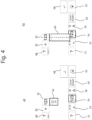
- Fig. 4 illustrates composition of another user application 18 that is intended to control the pump operation according to a voltage input.
- the user of the pump unit 2 has selected an input "Input 1" in the variable box 68.
- the user has just selected the numerical value box 72 and the drop-down menu box 66 gives a list that the user can choose from.
- the user is selecting the first two digits of the numerical value.
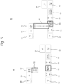
- Fig. 5 a) it can be seen that the first two digits of the numerical value are "01" indicated in the numerical value box 72.
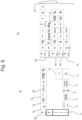
- the third digit of the numerical value is being selected and from drop-down menu box 66. The third digit is "0" and thus the value is "10" as illustrated in the numerical value box 72 in Fig. 6 a) .
- Fig. 6 b the completed user application 18 is shown.
- This user application 18 comprises four user application sequence sections 86, 88, 90, 92.
- the first section 86 defines that if the input voltage is below 10 volt and above 3 volt then the set point of the drive motor speed is adjusted linearly between 10% and 100% according to the input voltage. This is illustrated by a linear curve symbol 22.
- the second section 88 defines that if the input voltage is larger than or equal to 10 volt then the set point is set to 100%.
- the third section 90 defines that if the input voltage is 3 volt then the set point is set to 10%.
- the fourth section 92 defines that if the input voltage is lower than 3 volt then the pump stops.
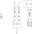
- Fig. 7 illustrates a user application 18 having two lines 94, 96.
- the first line 94 defines that if the head exceeds 4 meters (indicated wit "m") then the drive motor stops.
- the second line 96 defines that if the head equals or falls below 2 m then the drive motor 5 is activated.
- Such user application 18 may define that the drive motor 5 is set to start at the same hour every day.
- any possible input parameter with any suitable operator and a desired action of the drive motor to provide a program function or program sequence as a user application which allows to control the drive motor in response to input signals or input parameters.
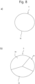
- Fig. 8a is a schematical view of a storage 6 of a control device for a prior art pump.
- the storage 6 comprises a basic function storage 36 that is used to store basic applications like a basic program, which cannot be modified by the user. These basic applications may be any type of application that is needed for carrying out the basic function of the pump unit 2.
- the user of the pump may change settings and parameters in the basic function storage 36 to adapt preset applications to the requested needs according to the prior art.
- the user of the pump unit is not able to create entire new applications as user functions or program sequences that are not already included in the basic function storage 36.
- Fig. 8b is a schematically view of storage means 6 according to the invention.
- the storage means 6 comprise a user application storage 34 that is configured to store user applications 18. These user applications 18 may be composed by the user or may be pre-installed by way of example. The user applications may also be downloaded to the user application storage 34.
- the storage means 6 further more comprise a basic function storage 36 that is used to store basic applications. These basic applications may be any type of application that is needed for carrying out the basic function of the pump unit 2.
- the storage means 6 moreover comprise an interpreter storage 38 that is allocated for the interpreter program and execution of the user applications 18 that are stored in the user application storage 34.
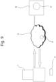
- Fig. 9 is a schematical view of a pump unit 2 according to one embodiment of the invention.
- the pump unit 2 is configured to communicate via the Internet 44.
- Information and data such as user applications 18 may be uploaded and downloaded to the pump unit 2.
- Weather forecast information 48 may by way of example be send to the pump unit 2.
- the pump unit 2 may also upload pump specific information 46 to an external receiver 39 by using the Internet 44.
- An external memory 50 is provided so that it would be possible to apply user applications 18 that are stored in the external memory 50.
- the user applications 18 may be downloaded from the Internet 44 to the external memory 50 by way of example.
- the pump unit 2 may receive sensor signals or signals as input parameters via a network connection.
- the pump unit 2 may be connected to a building management system or central heating control.
Landscapes
- Engineering & Computer Science (AREA)
- Mechanical Engineering (AREA)
- General Engineering & Computer Science (AREA)
- Physics & Mathematics (AREA)
- General Physics & Mathematics (AREA)
- Automation & Control Theory (AREA)
- Control Of Non-Positive-Displacement Pumps (AREA)
- Control Of Positive-Displacement Pumps (AREA)
- Structures Of Non-Positive Displacement Pumps (AREA)
Applications Claiming Priority (4)
| Application Number | Priority Date | Filing Date | Title |
|---|---|---|---|
| EP11007661.9A EP2573403B1 (de) | 2011-09-20 | 2011-09-20 | Pumpe |
| PCT/EP2012/068531 WO2013041616A1 (en) | 2011-09-20 | 2012-09-20 | Pump unit |
| EP12759483.6A EP2758670B1 (de) | 2011-09-20 | 2012-09-20 | Pumpeneinheit |
| EP18203201.1A EP3462032B1 (de) | 2011-09-20 | 2012-09-20 | Pumpeneinheit |
Related Parent Applications (2)
| Application Number | Title | Priority Date | Filing Date |
|---|---|---|---|
| EP12759483.6A Division EP2758670B1 (de) | 2011-09-20 | 2012-09-20 | Pumpeneinheit |
| EP18203201.1A Division EP3462032B1 (de) | 2011-09-20 | 2012-09-20 | Pumpeneinheit |
Publications (2)
| Publication Number | Publication Date |
|---|---|
| EP4234938A2 true EP4234938A2 (de) | 2023-08-30 |
| EP4234938A3 EP4234938A3 (de) | 2023-09-20 |
Family
ID=46852036
Family Applications (4)
| Application Number | Title | Priority Date | Filing Date |
|---|---|---|---|
| EP11007661.9A Active EP2573403B1 (de) | 2011-09-20 | 2011-09-20 | Pumpe |
| EP12759483.6A Revoked EP2758670B1 (de) | 2011-09-20 | 2012-09-20 | Pumpeneinheit |
| EP18203201.1A Active EP3462032B1 (de) | 2011-09-20 | 2012-09-20 | Pumpeneinheit |
| EP23172484.0A Pending EP4234938A3 (de) | 2011-09-20 | 2012-09-20 | Pumpeneinheit |
Family Applications Before (3)
| Application Number | Title | Priority Date | Filing Date |
|---|---|---|---|
| EP11007661.9A Active EP2573403B1 (de) | 2011-09-20 | 2011-09-20 | Pumpe |
| EP12759483.6A Revoked EP2758670B1 (de) | 2011-09-20 | 2012-09-20 | Pumpeneinheit |
| EP18203201.1A Active EP3462032B1 (de) | 2011-09-20 | 2012-09-20 | Pumpeneinheit |
Country Status (5)
| Country | Link |
|---|---|
| US (2) | US11625052B2 (de) |
| EP (4) | EP2573403B1 (de) |
| CN (2) | CN107989801B (de) |
| RU (1) | RU2610970C2 (de) |
| WO (1) | WO2013041616A1 (de) |
Families Citing this family (31)
| Publication number | Priority date | Publication date | Assignee | Title |
|---|---|---|---|---|
| EP2573403B1 (de) | 2011-09-20 | 2017-12-06 | Grundfos Holding A/S | Pumpe |
| EP3026183A1 (de) | 2012-03-07 | 2016-06-01 | Moen Incorporated | Elektronische armatur |
| EP2972902B1 (de) | 2013-03-15 | 2019-10-02 | Hayward Industries, Inc. | Modulares steuerungssystem für schwimmbad/spa |
| DE102013014669A1 (de) * | 2013-09-03 | 2015-03-05 | Eisenmann Ag | Einrichtung zum Bereitstellen eines Applikationsmaterials |
| FR3015587B1 (fr) * | 2013-12-24 | 2019-05-31 | Wilo Salmson France | Commande electronique pour une pompe de circulation, pompe de circulation et procede correspondant |
| FR3015586B1 (fr) * | 2013-12-24 | 2018-04-20 | Wilo Salmson France | Procede de depannage d'une installation hydraulique domestique |
| DE102014003249A1 (de) * | 2014-03-12 | 2015-09-17 | Wilo Se | Verfahren zur Konfiguration eines elektromotorischen Pumpenaggregats |
| US20160002942A1 (en) * | 2014-07-07 | 2016-01-07 | Paul Harvey Orlando | Pump Controller |
| WO2016078686A1 (en) | 2014-11-17 | 2016-05-26 | Grundfos Holding A/S | Method for authorising a handheld communication device access to a pump unit |
| WO2016086986A1 (en) | 2014-12-03 | 2016-06-09 | Grundfos Holding A/S | An electronic converter unit for retrofitting to an external part of a housing of a pump unit |
| CN108027620B (zh) | 2015-07-24 | 2021-08-06 | 流体处理有限责任公司 | 高级实时图形无传感器节能泵控制系统 |
| US10711788B2 (en) | 2015-12-17 | 2020-07-14 | Wayne/Scott Fetzer Company | Integrated sump pump controller with status notifications |
| US11720085B2 (en) | 2016-01-22 | 2023-08-08 | Hayward Industries, Inc. | Systems and methods for providing network connectivity and remote monitoring, optimization, and control of pool/spa equipment |
| US20170209338A1 (en) | 2016-01-22 | 2017-07-27 | Hayward Industries, Inc. | Systems and Methods for Providing Network Connectivity and Remote Monitoring, Optimization, and Control of Pool/Spa Equipment |
| DE102016005102A1 (de) | 2016-04-27 | 2017-11-02 | Wilo Se | Kommunikationseinrichtung, insbesondere für eine Kreiselpumpe |
| CN105889048A (zh) * | 2016-05-31 | 2016-08-24 | 池泉 | 一种泵组控制系统 |
| CN106089754B (zh) * | 2016-07-04 | 2018-12-25 | 宁波巨神制泵实业有限公司 | 基于“互联网+”的潜水泵实时故障诊断与维修方法 |
| CA3047090A1 (en) * | 2016-12-13 | 2018-06-21 | Wayne/Scott Fetzer Company | Pump communication module, pump system and methods relating thereto |
| EP3242035B1 (de) * | 2016-12-28 | 2021-08-18 | Grundfos Holding A/S | Verfahren zum betreiben mindestens eines pumpenaggregates von einer vielzahl von pumpenaggregaten |
| EP3242033B1 (de) * | 2016-12-30 | 2024-05-01 | Grundfos Holding A/S | Verfahren zum betreiben eines elektronisch gesteuerten pumpenaggregates |
| EP3382888B1 (de) * | 2017-03-31 | 2020-06-17 | Grundfos Holding A/S | Pumpenanordnung und steuerungsverfahren |
| EP3404267A1 (de) * | 2017-05-19 | 2018-11-21 | Grundfos Holding A/S | Pumpenanordnung |
| US20200129042A1 (en) * | 2017-05-25 | 2020-04-30 | Nec Corporation | Information processing apparatus, control method, and program |
| USD893552S1 (en) | 2017-06-21 | 2020-08-18 | Wayne/Scott Fetzer Company | Pump components |
| USD890211S1 (en) | 2018-01-11 | 2020-07-14 | Wayne/Scott Fetzer Company | Pump components |
| US20190301444A1 (en) * | 2018-03-30 | 2019-10-03 | Cole-Parmer Instrument Company Llc | Network monitoring and control of fluid handling apparatus |
| WO2020130767A1 (es) * | 2018-12-18 | 2020-06-25 | Bonasa Comercial S.A. De C.V. | Equipo de bombeo hidráulico multietapas con internet de las cosas |
| CN110360089B (zh) * | 2019-05-17 | 2021-07-27 | 保定雷弗流体科技有限公司 | 一种基于网络的调速型蠕动泵系统及其流量调节方法 |
| DE102019117383A1 (de) * | 2019-06-27 | 2020-12-31 | Rheinisch-Westfälische Technische Hochschule (RWTH) Aachen, Körperschaft des öffentlichen Rechts | System und Verfahren zur Regelung eines Medienparameters des Mediums auf der Sekundärseite eines Wärmeübertragers |
| IT201900012846A1 (it) * | 2019-07-25 | 2021-01-25 | Dab Pumps Spa | Dispositivo perfezionato di controllo e gestione di una o più elettropompe |
| DE102021000932A1 (de) * | 2021-02-22 | 2022-08-25 | KSB SE & Co. KGaA | Pumpe mit Bedienfeld |
Family Cites Families (84)
| Publication number | Priority date | Publication date | Assignee | Title |
|---|---|---|---|---|
| US3975622A (en) * | 1974-04-26 | 1976-08-17 | Forney Engineering Company | Programmable logic controller system |
| US4250563A (en) | 1979-08-09 | 1981-02-10 | Allen-Bradley Company | Expandable programmable controller |
| DE2938570A1 (de) | 1979-09-24 | 1981-04-23 | Siemens AG, 1000 Berlin und 8000 München | Schaltungsanordnung fuer einen mikrocomputer |
| US5143049A (en) * | 1987-10-19 | 1992-09-01 | Laing Karsten A | Pump for secondary circulation |
| EP0645685A3 (de) * | 1989-08-31 | 1995-11-02 | Yokogawa Electric Corp | Verfahren zur Steuerung eines Line Computers zur Durchführung und Relokierung eines übersetztes Programms aus einer Datenspeichersammlung. |
| JPH05224706A (ja) | 1992-02-07 | 1993-09-03 | Hitachi Ltd | 制御プログラム自動生成方法及び装置 |
| US5259445A (en) * | 1992-07-13 | 1993-11-09 | The Detroit Edison Company | Control for dual heating system including a heat pump and furnace |
| US5329991A (en) * | 1992-11-05 | 1994-07-19 | Hunter Fan Company | Pre-programmed electronic programmable thermostat |
| US6902378B2 (en) * | 1993-07-16 | 2005-06-07 | Helix Technology Corporation | Electronically controlled vacuum pump |
| JP3100817B2 (ja) | 1993-12-10 | 2000-10-23 | 三菱電機株式会社 | 制御プログラム設計支援装置 |
| TW307814B (de) * | 1994-09-20 | 1997-06-11 | Hitachi Ltd | |
| US5685844A (en) | 1995-01-06 | 1997-11-11 | Abbott Laboratories | Medicinal fluid pump having multiple stored protocols |
| US5788851A (en) | 1995-02-13 | 1998-08-04 | Aksys, Ltd. | User interface and method for control of medical instruments, such as dialysis machines |
| DE19511170A1 (de) * | 1995-03-28 | 1996-10-02 | Wilo Gmbh | Doppelpumpe mit übergeordneter Steuerung |
| US5812394A (en) * | 1995-07-21 | 1998-09-22 | Control Systems International | Object-oriented computer program, system, and method for developing control schemes for facilities |
| US5909368A (en) | 1996-04-12 | 1999-06-01 | Fisher-Rosemount Systems, Inc. | Process control system using a process control strategy distributed among multiple control elements |
| WO1998019389A1 (fr) | 1996-10-31 | 1998-05-07 | Ebara Corporation | Machine tournante a regulateur et inverseur integres |
| DE19742633C2 (de) | 1997-09-26 | 2000-12-07 | Fresenius Medical Care De Gmbh | Vorrichtung und Verfahren zur Sicherung von Touchscreen-Bedienungen |
| JP3803471B2 (ja) | 1997-10-03 | 2006-08-02 | 株式会社タムラ製作所 | はんだ付け装置 |
| US7539549B1 (en) * | 1999-09-28 | 2009-05-26 | Rockwell Automation Technologies, Inc. | Motorized system integrated control and diagnostics using vibration, pressure, temperature, speed, and/or current analysis |
| EP1062577A2 (de) * | 1998-12-08 | 2000-12-27 | Koninklijke Philips Electronics N.V. | Interpretiererprogrammausführungsverfahren |
| US6464464B2 (en) * | 1999-03-24 | 2002-10-15 | Itt Manufacturing Enterprises, Inc. | Apparatus and method for controlling a pump system |
| EP1063751B1 (de) * | 1999-06-22 | 2008-10-22 | Grundfos A/S | Pumpenaggregat |
| EP1290555A2 (de) * | 2000-03-20 | 2003-03-12 | Koninklijke Philips Electronics N.V. | Verfahren zur ausführung eines rechnerprogramms mit einem interpretator, rechnersystem und rechnerprogrammprodukt |
| DE10018866A1 (de) | 2000-04-14 | 2001-10-25 | Grundfos As | Pumpenaggregat |
| US20030225751A1 (en) * | 2000-07-06 | 2003-12-04 | Kim Si Han | Information searching system and method thereof |
| US7000220B1 (en) * | 2001-02-15 | 2006-02-14 | Booth Thomas W | Networked software development environment allowing simultaneous clients with combined run mode and design mode |
| US20080039977A1 (en) * | 2001-06-01 | 2008-02-14 | Tim Clark | Method and apparatus for remotely monitoring and controlling a pool or spa |
| DE20118185U1 (de) | 2001-11-09 | 2003-03-20 | Leybold Vakuum Gmbh | Vakuumpumpe |
| US7204823B2 (en) * | 2001-12-19 | 2007-04-17 | Medtronic Minimed, Inc. | Medication delivery system and monitor |
| US8250483B2 (en) * | 2002-02-28 | 2012-08-21 | Smiths Medical Asd, Inc. | Programmable medical infusion pump displaying a banner |
| US6852104B2 (en) * | 2002-02-28 | 2005-02-08 | Smiths Medical Md, Inc. | Programmable insulin pump |
| ES1054218Y (es) * | 2002-12-05 | 2003-10-16 | Bogemar Sl | Dispositivo de control de funcionamiento de electrobombas. |
| JP2004303114A (ja) * | 2003-04-01 | 2004-10-28 | Hitachi Ltd | インタープリタおよびネイティブコード実行方法 |
| US7844468B2 (en) | 2003-04-30 | 2010-11-30 | International Business Machines Corporation | Second site control of article transport processing |
| US8540493B2 (en) * | 2003-12-08 | 2013-09-24 | Sta-Rite Industries, Llc | Pump control system and method |
| JP2007536634A (ja) * | 2004-05-04 | 2007-12-13 | フィッシャー−ローズマウント・システムズ・インコーポレーテッド | プロセス制御システムのためのサービス指向型アーキテクチャ |
| US20060041222A1 (en) * | 2004-08-18 | 2006-02-23 | Medtronic, Inc. | Graphical infusion screen interface for programmable implantable medical device |
| US8019479B2 (en) * | 2004-08-26 | 2011-09-13 | Pentair Water Pool And Spa, Inc. | Control algorithm of variable speed pumping system |
| US7686589B2 (en) * | 2004-08-26 | 2010-03-30 | Pentair Water Pool And Spa, Inc. | Pumping system with power optimization |
| US8043070B2 (en) * | 2004-08-26 | 2011-10-25 | Pentair Water Pool And Spa, Inc. | Speed control |
| US8469675B2 (en) * | 2004-08-26 | 2013-06-25 | Pentair Water Pool And Spa, Inc. | Priming protection |
| US7874808B2 (en) * | 2004-08-26 | 2011-01-25 | Pentair Water Pool And Spa, Inc. | Variable speed pumping system and method |
| JP4281921B2 (ja) | 2004-11-04 | 2009-06-17 | ヤマハ発動機株式会社 | 燃料供給装置及びそれを備えた車両 |
| DE102004054004A1 (de) * | 2004-11-09 | 2006-05-11 | Pfeiffer Vacuum Gmbh | Vakuumpumpsystem und Signalerzeugungsverfahren |
| US20060258985A1 (en) * | 2005-05-11 | 2006-11-16 | Russell Claudia J | Graphical display of medication limits and delivery program |
| WO2006136202A1 (en) * | 2005-06-21 | 2006-12-28 | Itt Manufacturing Enterprises Inc. | Control system for a pump |
| GB2429603A (en) * | 2005-06-27 | 2007-02-28 | Ezurio Ltd | Wireless interface device able to convert between different communication standards |
| KR101364385B1 (ko) * | 2005-12-02 | 2014-02-17 | 엔테그리스, 아이엔씨. | 펌프 제어기를 인터페이스시키는 i/o 시스템, 방법 및디바이스 |
| US7707125B2 (en) * | 2005-12-07 | 2010-04-27 | Controlsoft, Inc. | Utility management system and method |
| US20070180207A1 (en) * | 2006-01-18 | 2007-08-02 | International Business Machines Corporation | Secure RFID backup/restore for computing/pervasive devices |
| US7777435B2 (en) | 2006-02-02 | 2010-08-17 | Aguilar Ray A | Adjustable frequency pump control system |
| US7925385B2 (en) * | 2006-03-08 | 2011-04-12 | Itt Manufacturing Enterprises, Inc | Method for optimizing valve position and pump speed in a PID control valve system without the use of external signals |
| DE102006022740A1 (de) | 2006-05-12 | 2007-11-15 | Ksb Aktiengesellschaft | Einrichtung zur Messwertübertragung |
| US8858526B2 (en) * | 2006-08-03 | 2014-10-14 | Smiths Medical Asd, Inc. | Interface for medical infusion pump |
| US20080126969A1 (en) * | 2006-08-03 | 2008-05-29 | Blomquist Michael L | Interface for medical infusion pump |
| US20080172031A1 (en) * | 2006-10-17 | 2008-07-17 | Blomquist Michael L | Insulin pump having correction factors |
| US9013322B2 (en) * | 2007-04-09 | 2015-04-21 | Lufkin Industries, Llc | Real-time onsite internet communication with well manager for constant well optimization |
| EP2153208A1 (de) * | 2007-04-12 | 2010-02-17 | Regents of the University of Minnesota | Systeme und verfahren zur analyse eines partikulären materials |
| US8774972B2 (en) | 2007-05-14 | 2014-07-08 | Flowserve Management Company | Intelligent pump system |
| US8287514B2 (en) * | 2007-09-07 | 2012-10-16 | Asante Solutions, Inc. | Power management techniques for an infusion pump system |
| US8032226B2 (en) * | 2007-09-07 | 2011-10-04 | Asante Solutions, Inc. | User profile backup system for an infusion pump device |
| AU2008217000B2 (en) | 2007-09-21 | 2012-02-09 | Multitrode Pty Ltd | A pumping installation controller |
| US20090200245A1 (en) * | 2008-02-08 | 2009-08-13 | Steinbrueck Brett D | System for Controlling Water in an Aquatic Facility |
| US20090254439A1 (en) | 2008-04-02 | 2009-10-08 | Manufacturing Resources International, Inc. | Touch Screen Device With Fuel Pump Access |
| US8523797B2 (en) * | 2008-05-08 | 2013-09-03 | Hospira, Inc. | Automated point-of-care fluid testing device and method of using the same |
| JP5168012B2 (ja) * | 2008-07-28 | 2013-03-21 | 株式会社ジェイテクト | プログラマブルコントローラのプログラム編集装置 |
| EP2151578B1 (de) * | 2008-08-04 | 2019-09-18 | Grundfos Management A/S | Umwälzpumpenaggregat |
| US8452953B2 (en) * | 2008-09-05 | 2013-05-28 | Roche Diagnostics Operations, Inc. | Insulin pump programming software for selectively modifying configuration data |
| WO2010042406A1 (en) | 2008-10-06 | 2010-04-15 | Pentair Water Pool And Spa, Inc. | Method of operating a safety vacuum release system |
| EP2411157A2 (de) | 2009-03-25 | 2012-02-01 | Briggs & Stratton Corporation | Druckerhöhungswasserpumpe |
| CN101560971B (zh) * | 2009-04-03 | 2011-05-11 | 杨治金 | 泵组能源效率自动化控制系统及其控制方法 |
| US8436559B2 (en) * | 2009-06-09 | 2013-05-07 | Sta-Rite Industries, Llc | System and method for motor drive control pad and drive terminals |
| US8573951B1 (en) * | 2009-10-02 | 2013-11-05 | Play-It-Safe Technologies, LLC | Pool recirculation pump safety system and method |
| US9164501B2 (en) | 2009-10-05 | 2015-10-20 | Fisher-Rosemount Systems, Inc. | Methods and apparatus to manage data uploading in a process control environment |
| US8543245B2 (en) * | 2009-11-20 | 2013-09-24 | Halliburton Energy Services, Inc. | Systems and methods for specifying an operational parameter for a pumping system |
| CA2789141C (en) * | 2010-02-05 | 2018-06-12 | Deka Products Limited Partnership | Infusion pump apparatus, method and system |
| WO2011106557A1 (en) * | 2010-02-25 | 2011-09-01 | Hayward Industries, Inc. | Pump controller with external device control capability |
| US10030647B2 (en) * | 2010-02-25 | 2018-07-24 | Hayward Industries, Inc. | Universal mount for a variable speed pump drive user interface |
| US8546984B2 (en) * | 2010-11-03 | 2013-10-01 | Nidec Motor Corporation | Pump motor control assembly |
| US8489242B2 (en) | 2011-01-06 | 2013-07-16 | General Electric Company | Home energy management system incorporating a pool pump |
| EP2573403B1 (de) | 2011-09-20 | 2017-12-06 | Grundfos Holding A/S | Pumpe |
| FI127255B (en) * | 2011-11-02 | 2018-02-15 | Abb Technology Oy | Procedure and controller for operating a pump system |
| FR2990007B1 (fr) * | 2012-04-26 | 2014-04-18 | Schneider Toshiba Inverter | Procede et systeme d'identification et de commande d'une pompe centrifuge |
-
2011
- 2011-09-20 EP EP11007661.9A patent/EP2573403B1/de active Active
-
2012
- 2012-09-20 EP EP12759483.6A patent/EP2758670B1/de not_active Revoked
- 2012-09-20 CN CN201711372320.XA patent/CN107989801B/zh active Active
- 2012-09-20 EP EP18203201.1A patent/EP3462032B1/de active Active
- 2012-09-20 US US14/345,767 patent/US11625052B2/en active Active
- 2012-09-20 RU RU2014115714A patent/RU2610970C2/ru active
- 2012-09-20 WO PCT/EP2012/068531 patent/WO2013041616A1/en active Application Filing
- 2012-09-20 CN CN201280045833.9A patent/CN103814222A/zh active Pending
- 2012-09-20 EP EP23172484.0A patent/EP4234938A3/de active Pending
-
2022
- 2022-09-23 US US17/951,509 patent/US11966238B2/en active Active
Also Published As
| Publication number | Publication date |
|---|---|
| RU2014115714A (ru) | 2015-10-27 |
| EP3462032A1 (de) | 2019-04-03 |
| WO2013041616A9 (en) | 2013-05-23 |
| RU2610970C2 (ru) | 2017-02-17 |
| EP2573403B1 (de) | 2017-12-06 |
| US20140229023A1 (en) | 2014-08-14 |
| EP2758670A1 (de) | 2014-07-30 |
| WO2013041616A1 (en) | 2013-03-28 |
| EP2758670B1 (de) | 2018-10-31 |
| US11625052B2 (en) | 2023-04-11 |
| EP2573403A1 (de) | 2013-03-27 |
| CN107989801A (zh) | 2018-05-04 |
| EP3462032B1 (de) | 2023-06-07 |
| US20230020116A1 (en) | 2023-01-19 |
| CN103814222A (zh) | 2014-05-21 |
| EP4234938A3 (de) | 2023-09-20 |
| CN107989801B (zh) | 2021-04-09 |
| US11966238B2 (en) | 2024-04-23 |
| EP3462032C0 (de) | 2023-06-07 |
Similar Documents
| Publication | Publication Date | Title |
|---|---|---|
| US11966238B2 (en) | Pump unit | |
| EP2169488B1 (de) | Humanes Schnittstellenmodul für einen Motorantrieb | |
| RU2640869C2 (ru) | Насосный агрегат, конфигурирующая система насосного агрегата и способ | |
| KR101823847B1 (ko) | 모터 제어 장치의 커스터마이즈 방법, 및 모터 제어 장치 | |
| US8473110B2 (en) | Systems and methods for controlling operation of a motor | |
| US8380354B2 (en) | Motor controller for air-conditioner fan and method for controlling air-conditioner fan | |
| US8683017B2 (en) | Web-based configuration of distributed automation systems | |
| JP5410550B2 (ja) | ヒューマンマシンインターフェイスナビゲーションツール | |
| WO2016040174A1 (en) | Method and system for power provisioning | |
| JP2013000874A (ja) | 電動工具 | |
| KR20170057487A (ko) | 모바일 리모컨 시스템을 이용한 제어장치의 상태 인식 방법 및 상태 인식 장치 | |
| JP2003259688A (ja) | パラメータ設定装置 | |
| CN106150998A (zh) | 泵装置、远程监视装置及泵装置的控制方法 | |
| US20170356450A1 (en) | Pump control design toolbox technique for variable speed pumping applications | |
| US10908590B2 (en) | System and method for adjusting an operation of a motor | |
| AU2023200750B2 (en) | Control of an electric appliance by means of a battery pack | |
| CN203933453U (zh) | 电动软启动器 | |
| CN203872089U (zh) | 电动软启动器 | |
| KR20000055057A (ko) | 인버터 시스템의 시퀀스 프로그래머 구현 장치 | |
| FI122305B (fi) | Taajuusmuuttaja | |
| KR20220130846A (ko) | 모터 대응형 무선제어모듈 및 이를 이용한 모터 무선제어시스템 | |
| AU2023200957A1 (en) | Identification, configuration and control of an electric appliance | |
| JP2020145804A5 (de) | ||
| JP2008287619A (ja) | Plcモジュール、ビルディングブロックタイプのプログラマブルコントローラ、携帯型通信デバイス |
Legal Events
| Date | Code | Title | Description |
|---|---|---|---|
| PUAI | Public reference made under article 153(3) epc to a published international application that has entered the european phase |
Free format text: ORIGINAL CODE: 0009012 |
|
| STAA | Information on the status of an ep patent application or granted ep patent |
Free format text: STATUS: THE APPLICATION HAS BEEN PUBLISHED |
|
| PUAL | Search report despatched |
Free format text: ORIGINAL CODE: 0009013 |
|
| AC | Divisional application: reference to earlier application |
Ref document number: 2758670 Country of ref document: EP Kind code of ref document: P Ref document number: 3462032 Country of ref document: EP Kind code of ref document: P |
|
| AK | Designated contracting states |
Kind code of ref document: A2 Designated state(s): AL AT BE BG CH CY CZ DE DK EE ES FI FR GB GR HR HU IE IS IT LI LT LU LV MC MK MT NL NO PL PT RO RS SE SI SK SM TR |
|
| AK | Designated contracting states |
Kind code of ref document: A3 Designated state(s): AL AT BE BG CH CY CZ DE DK EE ES FI FR GB GR HR HU IE IS IT LI LT LU LV MC MK MT NL NO PL PT RO RS SE SI SK SM TR |
|
| RIC1 | Information provided on ipc code assigned before grant |
Ipc: F04D 15/00 20060101AFI20230814BHEP |
|
| STAA | Information on the status of an ep patent application or granted ep patent |
Free format text: STATUS: REQUEST FOR EXAMINATION WAS MADE |
|
| 17P | Request for examination filed |
Effective date: 20231005 |
|
| RBV | Designated contracting states (corrected) |
Designated state(s): AL AT BE BG CH CY CZ DE DK EE ES FI FR GB GR HR HU IE IS IT LI LT LU LV MC MK MT NL NO PL PT RO RS SE SI SK SM TR |