US8436559B2 - System and method for motor drive control pad and drive terminals - Google Patents
System and method for motor drive control pad and drive terminals Download PDFInfo
- Publication number
- US8436559B2 US8436559B2 US12/481,475 US48147509A US8436559B2 US 8436559 B2 US8436559 B2 US 8436559B2 US 48147509 A US48147509 A US 48147509A US 8436559 B2 US8436559 B2 US 8436559B2
- Authority
- US
- United States
- Prior art keywords
- controller
- pump
- drive
- fault
- motor
- Prior art date
- Legal status (The legal status is an assumption and is not a legal conclusion. Google has not performed a legal analysis and makes no representation as to the accuracy of the status listed.)
- Active, expires
Links
- 238000000034 method Methods 0.000 title claims abstract description 40
- 239000004576 sand Substances 0.000 claims description 4
- 230000002262 irrigation Effects 0.000 claims description 2
- 238000003973 irrigation Methods 0.000 claims description 2
- 230000008569 process Effects 0.000 abstract description 8
- 238000001514 detection method Methods 0.000 abstract description 7
- 239000012530 fluid Substances 0.000 abstract description 3
- 238000004891 communication Methods 0.000 abstract description 2
- XLYOFNOQVPJJNP-UHFFFAOYSA-N water Substances O XLYOFNOQVPJJNP-UHFFFAOYSA-N 0.000 description 12
- 230000002265 prevention Effects 0.000 description 9
- 230000009471 action Effects 0.000 description 5
- 239000004973 liquid crystal related substance Substances 0.000 description 5
- 239000003990 capacitor Substances 0.000 description 4
- 230000008859 change Effects 0.000 description 4
- 230000007423 decrease Effects 0.000 description 4
- 230000001960 triggered effect Effects 0.000 description 3
- CYTYCFOTNPOANT-UHFFFAOYSA-N Perchloroethylene Chemical compound ClC(Cl)=C(Cl)Cl CYTYCFOTNPOANT-UHFFFAOYSA-N 0.000 description 2
- 230000008878 coupling Effects 0.000 description 2
- 238000010168 coupling process Methods 0.000 description 2
- 238000005859 coupling reaction Methods 0.000 description 2
- 230000006698 induction Effects 0.000 description 2
- 230000004048 modification Effects 0.000 description 2
- 238000012986 modification Methods 0.000 description 2
- 230000009286 beneficial effect Effects 0.000 description 1
- 230000033228 biological regulation Effects 0.000 description 1
- 238000010276 construction Methods 0.000 description 1
- 230000000694 effects Effects 0.000 description 1
- 230000005611 electricity Effects 0.000 description 1
- 238000009434 installation Methods 0.000 description 1
- 239000000463 material Substances 0.000 description 1
- 238000005086 pumping Methods 0.000 description 1
- 230000004044 response Effects 0.000 description 1
Images


Classifications
-
- F—MECHANICAL ENGINEERING; LIGHTING; HEATING; WEAPONS; BLASTING
- F17—STORING OR DISTRIBUTING GASES OR LIQUIDS
- F17D—PIPE-LINE SYSTEMS; PIPE-LINES
- F17D3/00—Arrangements for supervising or controlling working operations
- F17D3/01—Arrangements for supervising or controlling working operations for controlling, signalling, or supervising the conveyance of a product
-
- F—MECHANICAL ENGINEERING; LIGHTING; HEATING; WEAPONS; BLASTING
- F04—POSITIVE - DISPLACEMENT MACHINES FOR LIQUIDS; PUMPS FOR LIQUIDS OR ELASTIC FLUIDS
- F04B—POSITIVE-DISPLACEMENT MACHINES FOR LIQUIDS; PUMPS
- F04B17/00—Pumps characterised by combination with, or adaptation to, specific driving engines or motors
- F04B17/03—Pumps characterised by combination with, or adaptation to, specific driving engines or motors driven by electric motors
-
- F—MECHANICAL ENGINEERING; LIGHTING; HEATING; WEAPONS; BLASTING
- F04—POSITIVE - DISPLACEMENT MACHINES FOR LIQUIDS; PUMPS FOR LIQUIDS OR ELASTIC FLUIDS
- F04B—POSITIVE-DISPLACEMENT MACHINES FOR LIQUIDS; PUMPS
- F04B47/00—Pumps or pumping installations specially adapted for raising fluids from great depths, e.g. well pumps
- F04B47/06—Pumps or pumping installations specially adapted for raising fluids from great depths, e.g. well pumps having motor-pump units situated at great depth
-
- F—MECHANICAL ENGINEERING; LIGHTING; HEATING; WEAPONS; BLASTING
- F04—POSITIVE - DISPLACEMENT MACHINES FOR LIQUIDS; PUMPS FOR LIQUIDS OR ELASTIC FLUIDS
- F04B—POSITIVE-DISPLACEMENT MACHINES FOR LIQUIDS; PUMPS
- F04B49/00—Control, e.g. of pump delivery, or pump pressure of, or safety measures for, machines, pumps, or pumping installations, not otherwise provided for, or of interest apart from, groups F04B1/00 - F04B47/00
- F04B49/06—Control using electricity
- F04B49/065—Control using electricity and making use of computers
-
- F—MECHANICAL ENGINEERING; LIGHTING; HEATING; WEAPONS; BLASTING
- F04—POSITIVE - DISPLACEMENT MACHINES FOR LIQUIDS; PUMPS FOR LIQUIDS OR ELASTIC FLUIDS
- F04B—POSITIVE-DISPLACEMENT MACHINES FOR LIQUIDS; PUMPS
- F04B49/00—Control, e.g. of pump delivery, or pump pressure of, or safety measures for, machines, pumps, or pumping installations, not otherwise provided for, or of interest apart from, groups F04B1/00 - F04B47/00
- F04B49/10—Other safety measures
-
- F—MECHANICAL ENGINEERING; LIGHTING; HEATING; WEAPONS; BLASTING
- F04—POSITIVE - DISPLACEMENT MACHINES FOR LIQUIDS; PUMPS FOR LIQUIDS OR ELASTIC FLUIDS
- F04D—NON-POSITIVE-DISPLACEMENT PUMPS
- F04D13/00—Pumping installations or systems
- F04D13/02—Units comprising pumps and their driving means
- F04D13/06—Units comprising pumps and their driving means the pump being electrically driven
- F04D13/08—Units comprising pumps and their driving means the pump being electrically driven for submerged use
-
- G—PHYSICS
- G07—CHECKING-DEVICES
- G07C—TIME OR ATTENDANCE REGISTERS; REGISTERING OR INDICATING THE WORKING OF MACHINES; GENERATING RANDOM NUMBERS; VOTING OR LOTTERY APPARATUS; ARRANGEMENTS, SYSTEMS OR APPARATUS FOR CHECKING NOT PROVIDED FOR ELSEWHERE
- G07C9/00—Individual registration on entry or exit
- G07C9/30—Individual registration on entry or exit not involving the use of a pass
- G07C9/32—Individual registration on entry or exit not involving the use of a pass in combination with an identity check
- G07C9/33—Individual registration on entry or exit not involving the use of a pass in combination with an identity check by means of a password
Definitions
- Submersible well pumps are connected to above-ground drive systems that control the operation of the pump.
- Some conventional pump controllers include only start capacitors and relays to turn the pump on and off based on system pressure. These pump controllers have limited capabilities with respect to pump control, safety, and customization.
- VFDs Variable frequency drives
- Conventional drives have also generally been designed for use with particular types of motors and often cannot be used to retrofit motors that are already installed in the well, especially two-wire, single-phase motors.
- a method of installing a drive including a control pad can include entering a service factor current value using the control pad and selecting a two-wire, single-phase motor; a three-wire, single-phase motor; or a three-phase motor.
- the method can also include entering a current time using the control pad, entering a current date using the control pad, and engaging a pump-out button or an automatic start button on the control pad.
- Some embodiments of the invention also provide a method including providing a password protection mode to prevent settings from being changed using the control pad until a password is provided.
- the method can also include automatically entering the password protection mode after a predetermined time period once the installer finishes connecting the drive to the motor and finishes a set up operation using the control pad.
- Some embodiments provide a method of controlling a pump installed in a new well.
- the method can include providing a pump-out button on the control pad.
- the pump-out button can be engaged once the pump is installed in the new well and once the drive is connected to the motor.
- the method can include operating the pump in a pump-out mode when the pump-out button is engaged.
- the pump-out mode can provide an open discharge of sand and dirt from the new well.
- a method can include providing a drive having an input power terminal block, an output power terminal block, one or more analog input terminals, one or more digital input terminals, and one or more digital output terminals.
- the method can include connecting a run/enable switch to the digital input terminal, an indicator device to the digital output terminal, a status output to the digital output terminal, and/or a fault alarm output to the digital output terminal.
- FIG. 1 is a perspective view of a variable frequency drive according to one embodiment of the invention.
- FIG. 2 is a perspective view of the variable frequency drive of FIG. 1 with a cover removed.
- FIG. 3 is an interior view of the variable frequency drive of FIG. 1 .
- FIG. 4 is a front view of a control pad of the variable frequency drive of FIG. 1 .
- FIG. 5 is a schematic view of the variable frequency drive of FIG. 1 installed in a fluid system.
- FIG. 6 is a schematic illustration of the variable frequency drive of FIG. 1 .
- FIG. 7 is a flow chart illustrating a pump out operation.
- FIG. 8 is a flow chart illustrating an automatic line fill operation.
- FIG. 9 is a flow chart illustrating a manual line fill operation.
- FIG. 10 is a flow chart illustrating a stop operation.
- FIG. 11 is a flow chart illustrating a proportional/integral/derivative (PID) mode control operation.
- FIG. 12 is a flow chart illustrating a sleep mode operation.
- FIG. 13 is a flow chart illustrating an alternate sleep mode operation.
- FIG. 14 is a flow chart illustrating a digital input control operation.
- FIG. 15 is a flow chart illustrating a relay output control operation.
- FIG. 16 is a flow chart illustrating a main menu.
- FIG. 17 is a flow chart illustrating a settings menu.
- FIG. 18 is a flow chart illustrating a time parameter menu.
- FIG. 19 is a flow chart illustrating a PID control parameter menu.
- FIG. 20 is a flow chart illustrating a sleep parameter menu.
- FIG. 21 is a flow chart illustrating a password parameter menu.
- FIG. 22 is a flow chart illustrating an external set point parameter menu.
- FIG. 23 is a flow chart illustrating a motor parameter menu.
- FIG. 24 is a flow chart illustrating a sensor parameter menu.
- FIG. 25 is a flow chart illustrating a pipe break parameter menu.
- FIG. 26 is a flow chart illustrating a dry run parameter menu.
- FIG. 27 is a flow chart illustrating an input/output parameter menu.
- FIG. 28 is a flow chart illustrating a reset parameter menu.
- FIG. 29 is a flow chart illustrating a backdoor parameter menu.
- FIG. 30 is a flow chart illustrating an overheat prevention operation.
- FIG. 31 is a flow chart illustrating an overcurrent prevention operation.
- FIG. 32 is a flow chart illustrating a jam prevention operation.
- FIG. 33 is a flow chart illustrating a pipe break prevention operation.
- FIG. 34 is a flow chart illustrating a dry run detection operation.
- FIG. 35 is a flow chart illustrating a dry run fault operation.
- FIG. 36 is a flow chart illustrating a jam fault operation.
- FIG. 37 is a flow chart illustrating an overtemperature fault operation.
- FIG. 38 is a flow chart illustrating an overcurrent fault operation.
- FIG. 39 is a flow chart illustrating an overvoltage fault operation.
- FIG. 40 is a flow chart illustrating an internal fault operation.
- FIG. 41 is a flow chart illustrating a ground fault operation.
- FIG. 42 is a flow chart illustrating an open transducer fault operation.
- FIG. 43 is a flow chart illustrating a shorted transducer fault operation.
- FIGS. 44A-44B are flow charts illustrating a multiple faults operation.
- FIG. 45 is a flow chart illustrating an undervoltage fault operation.
- FIG. 46 is a flow chart illustrating a hardware fault operation.
- FIG. 47 is a flow chart illustrating an external fault operation.
- FIG. 48 is a flow chart illustrating a pump out button control operation.
- FIG. 49 is a flow chart illustrating a pressure preset button control operation.
- FIG. 50 is a flow chart illustrating a main menu button control operation.
- FIG. 51 is a flow chart illustrating a fault log button control operation.
- FIG. 52 is a flow chart illustrating an enter button control operation.
- FIG. 53 is a flow chart illustrating a back button control operation.
- FIG. 54 is a flow chart illustrating an up/down button control operation.
- FIG. 55 is a flow chart illustrating a left/right button control operation.
- FIG. 56 is a flow chart illustrating a password button control operation.
- FIG. 57 is a flow chart illustrating a language button control operation.
- FIG. 58 is a flow chart illustrating a status button control operation.
- FIG. 59 is a flow chart illustrating a stop button control operation.
- FIG. 60 is a flow chart illustrating an automatic start button control operation.
- FIG. 61 is a flow chart illustrating a fault reset button control operation.
- FIGS. 62A-62D are flow charts illustrating LED indicator control operations.
- FIGS. 63A-63D are flow charts illustrating error display control operations.
- FIG. 1 illustrates a variable frequency drive (VFD, hereinafter “the drive”) 10 according to one embodiment of the invention.
- the drive 10 can be used to control the operation of an AC induction motor 11 that drives a water pump 12 (as shown in FIG. 5 ).
- the drive 10 can be used in a residential, commercial, or industrial pump system to maintain a substantially constant pressure.
- the motor 11 and pump 12 can be a submersible type or an above-ground type.
- the drive 10 can monitor certain operating parameters and control the operation of the motor 11 in response to the sensed conditions.
- the drive 10 can include an enclosure 13 and a control pad 14 .
- the enclosure 13 can be a NEMA 1 indoor enclosure or a NEMA 3R outdoor enclosure. In one embodiment, the enclosure 13 can have a width of about 9.25 inches, a height of about 17.5 inches, and a depth of about 6.0 inches.
- the enclosure 13 can include a keyhole mount 16 for fast and easy installation onto a wall, such as a basement wall.
- the enclosure 13 can include slots 18 through which air that cools the drive 10 can pass out of the enclosure 13 .
- the control pad 14 can be positioned within the enclosure 13 for access through a rectangular aperture 20 .
- the enclosure 13 can include a removable cover 22 with attached side panels. Removing the cover 22 allows access to a wiring area 24 , which is located adjacent to a bottom panel 25 of the enclosure 13 with several conduit holes 26 . As shown in FIGS. 2 and 3 , the wiring area 24 is free of any electrical components or printed circuit board material that may impede any wiring.
- the wiring area 24 can provide access to an input power terminal block 28 , input/output (I/O) spring terminals 30 , and an output power terminal block 32 .
- Each one of the conduit holes 26 can be aligned with one of the input power terminal block 28 , the I/O spring terminals 30 , and the output power terminal block 32 .
- the I/O spring terminals 30 can include digital output terminals 30 A, digital input terminals 308 , I/O power supply terminals 30 C, and analog input terminals 30 D.
- the wiring area 24 can include a wiring space 34 between the bottom panel 25 and the input power terminal block 28 , the I/O spring terminals 30 , and the output power terminal block 32 .
- the wiring space 34 can be between about three inches and about six inches in height in order to allow enough room for an installer to access the input power terminal block 28 , the I/O spring terminals 30 , and the output power terminal block 32 .
- the input power terminal block 28 , I/O spring terminals 30 , and the output power terminal block 32 can be used to control the motor 11 and to provide output information in any number of configurations and applications.
- Various types of inputs can be provided to the drive 10 to be processed and used to control the motor 11 .
- the analog input terminals 30 D can receive analog inputs and the digital input terminals 30 B can receive digital inputs.
- any suitable type of run/enable switch can be provided as an input to the drive 10 (e.g., via the digital input terminals 30 B).
- the run/enable switch can be part of a lawn irrigation system, a spa pump controller, a pool pump controller, a float switch, or a clock/timer.
- the digital input terminals 30 B can accept a variety of input voltages, such as voltages ranging from about 12 volts to about 240 volts, direct current (DC) or alternating current (AC).
- the digital output terminals 30 A can connect to digital outputs, such as relay outputs. Any suitable type of indicator device, status output, or fault alarm output can serve as a digital, or relay, output (e.g., be connected to the digital output terminals 30 A).
- a status output can be used to control a second pump, for example, to run the second pump when the pump 12 is running.
- a fault alarm output can, for example, place a call using a pre-defined phone number, signal a residential alarm system, and/or shut down the pump 12 when a fault is determined. For example, when there is a pipe break fault (as described below with reference to FIG. 33 ), the digital output terminals 30 A can energize a relay output, causing the pre-defined phone number to be automatically dialed.
- the input power terminal block 28 , the I/O spring terminals 30 , and the output power terminal block 32 can all be coupled to a drive circuit board (not shown), for connection to a controller 75 (as shown in FIG. 6 ) of the drive 10 . Further, the input power terminal block 28 and/or the output power terminal block 32 can be removable and replaceable without replacing the drive circuit board or the entire drive 10 .
- a control pad 14 of the drive 10 can include a backlit liquid crystal display 36 and several control buttons 38 .
- the control buttons 38 can include a pump-out button 40 , a pressure preset button 42 , a main menu button 44 , and a fault log button 46 .
- the control buttons 38 can also include a keypad lockout button 48 and a language button 50 .
- the control pad 14 can include several directional buttons 52 , a back button 54 , and an enter button 56 .
- the control pad 14 can further include a status button 58 , a stop button 60 , an automatic start button 62 , and a fault reset button 64 .
- the control pad 14 can include light emitting diode (LED) indicators 66 , to indicate a status of the drive 10 , such as an ON LED 68 , a Warning LED 70 , and a Fault LED 72 .
- LED light emitting diode
- the drive 10 can include an electromagnetic interference (EMI) filter 74 .
- the EMI filter 74 can reduce electrical noise generated by the motor 11 , especially noise that interferes with AM radio stations.
- the drive 10 can reduce electrical noise while simultaneously being compatible with a Ground Fault Circuit Interrupter (GFCI).
- GFCI Ground Fault Circuit Interrupter
- An unintentional electric path between a source of current and a grounded surface is generally referred to as a “ground fault.” Ground faults occur when current is leaking somewhere, and in effect, electricity is escaping to the ground.
- the drive 10 can be compatible with a number of different types of motors 11 , including, but not limited to, AC induction motors that are two-wire permanent split capacitor (PSC) single-phase motors; three-wire single-phase motors; or three-phase motors.
- the drive 10 can be connected to a previously-installed motor 11 in order to retrofit the controls for the motor 11 . If the motor is a single-phase motor, the installer can use the control pad 14 to select either two-wire or three-wire.
- the drive 10 can automatically generate a first waveform and a second waveform with the second waveform having a phase angle of about 90 degrees offset from the first waveform.
- the controller 75 (as shown in FIG. 6 ) can automatically set a minimum and maximum frequency allowance for the motor 11 depending on the selection.
- the drive 10 can be programmed to operate after a simple start-up process by a user using the control pad 14 .
- the start-up process can be a five-step process for a single-phase motor 11 and a four-step process for a three-phase motor 11 .
- the start-up process for a single-phase motor 11 can include (1) entering a service factor current value, (2) selecting either a two-wire motor or a three-wire motor, (3) entering a current time, (4) entering a current date, and (5) engaging the pump-out button 40 or the automatic start button 62 .
- the start-up process for a three-phase motor 11 can include (1) entering a service factor current value, (2) entering a current time, (3) entering a current date, and (4) engaging the pump-out button 40 or the automatic start button 62 .
- the pump-out button 40 can be used to enter the drive 10 in a pump out mode to clean out sand and dirt from a newly-dug well.
- the pump-out button 40 can be engaged once the pump 12 is installed in the new well and once the drive 10 is connected to the motor 11 .
- the pump-out mode can provide an open discharge of sand and dirt from the well, for example, onto a lawn.
- the drive 10 can operate the pump 12 in the pump out mode at about 45 Hertz (Hz).
- the pump out mode operation is further described below with respect to FIG. 7
- a pump-out button control operation is further described below with respect to FIG. 48 .
- the controller 75 can include software executed by a digital signal processor (DSP, as shown in FIG. 6 ) or a microprocessor and can perform real-time control including soft-start, speed regulation, and motor protection.
- DSP digital signal processor
- the drive 10 can be controlled to maintain substantially constant water pressure in a water system that may or may not utilize a tank.
- the controller 75 can implement a classical Proportional/Integral/Derivative (PID) method using pressure error as an input.
- Pressure error can be calculated by subtracting an actual water pressure from the desired water pressure (i.e., a pressure set point).
- An updated speed control command can then be generated by multiplying the pressure error by a proportional gain, multiplying the integral of the pressure error by an integral gain, multiplying the derivative of the pressure error by a derivative gain, and summing the results.
- the controller 75 can increase or decrease the speed of the motor 11 to maintain a constant pressure set point. The PID mode is further described below with respect to FIG. 11 .
- the controller 75 can determine the actual water pressure value from an electronic pressure transducer 15 (e.g., in communication with the controller 75 via the analog input terminals 30 D).
- the pressure transducer 15 can be located near a pressure tank 17 fluidly coupled to the pump 12 .
- motor 11 If motor 11 is off (i.e., not being driven), water pressure can still be monitored, but no actions are taken until the pressure falls below a certain value (e.g., a low band pressure value). If the water pressure falls below the low band pressure, the controller 75 can restart the motor 11 .
- the low band pressure can be set, or defaulted, to 1-10 pounds per square inch (PSI) lower than the pressure set point.
- PSI pounds per square inch
- PID mode normal operation with PID control
- one of two conditions can trigger the controller 75 to turn the motor 11 off.
- a first condition can be if a sleep mode (described with respect to FIG. 12 ) is triggered.
- a second condition can be if the pressure exceeds a certain safety value (i.e., about 20 PSI above the pressure set point).
- a certain safety value i.e., about 20 PSI above the pressure set point.
- Other conditions that can stop the drive 10 are various faults (described further below), the user pressing the stop button 60 , and lack of a digital input for an optional run enable mode.
- the controller 75 can regulate pump speed in a continuous fashion using PID control as long as the pressure remains below the safety pressure value, such as about 20 PSI above the pressure set point.
- the drive 10 can stop the motor 11 whenever the actual pressure exceeds the safety pressure value.
- the pressure can remain constant at approximately the pressure set point. Large instantaneous changes in flow requirements can result in variations from the desired pressure band. For example, if flow is stopped, causing the pressure to quickly increase, the motor 11 can be stopped (i.e., set to 0 Hz). This can be considered an alternate sleep mode operation and is further described below with respect to FIG. 13 .
- FIGS. 7-15 are flow charts describing pump control according to some embodiments of the invention.
- the flow chart of FIG. 7 illustrates when the controller 75 receives a signal to run the pump in the pump out mode 76 (e.g., when the pump-out button 40 is pressed).
- the controller 75 first determines, at step 78 , if the pump is already running in pump out mode. If so, the pump is being run at a correct, fixed frequency for pump out mode (step 80 ). If not, the controller 75 , at step 82 , ramps up the input frequency of power to the motor 11 to the correct frequency, then proceeds to step 80 .
- FIG. 8 illustrates an automatic line fill operation 84 , according to some embodiments.
- This operation can automatically run at drive start-up (e.g., when the drive 10 is powered up, after a power interruption, when the motor 11 is restarted, or when the automatic start button 62 is pressed).
- the motor may be off (i.e., at 0 Hz) at the beginning of this operation.
- the controller 75 first can ramp up the frequency driving the motor from 0 Hz to about 45 Hz in less than a first time period, such as about two seconds (step 86 ). In a second time period, such as about two minutes, or about five minutes in some embodiments, the controller 75 can start to ramp up the frequency from, for example, about 45 Hz to about 55 Hz (step 88 ).
- the controller 75 determines the pressure via input from the pressure transducer 15 (step 90 ). If the sensed pressure has reached a minimum pressure, or pressure set point (e.g., about 10 PSI), indicating the line has been filled, the fill operation is completed and the controller 75 enters PID mode (step 92 ). However, if the sensed pressure is less than 10 PSI at step 90 , the controller 75 determines if the second time period (e.g., about two minutes or about five minutes) has passed (step 94 ). If the second period has not passed, the controller 75 reverts back to step 88 and continues to ramp the motor frequency.
- a minimum pressure, or pressure set point e.g., about 10 PSI
- the controller 75 will hold the frequency at about 55 Hz for about one minute (step 96 ). The controller 75 then determines if the sensed pressure is about 10 PSI (step 98 ). If the sensed pressure is about 10 PSI, indicating the line has been filled, the fill operation is completed and the controller 75 enters PID mode (step 92 ). However, if the sensed pressure is still less than 10 PSI at step 90 , the controller 75 determines if one minute has passed (step 100 ). If one minute has not passed, the controller 75 reverts back to step 96 . If one minute has passed, a dry run fault is recognized and a dry run fault operation is executed (step 102 ) (e.g., the system is stopped).
- step 88 can include setting the frequency to about 45 Hz for the second time period, and if the sensed pressure is less than 10 PSI after the second time period, repeating step 88 with the frequency set to about 50 Hz for another second time period. If the sensed pressure is still less than 10 PSI after the second time period while at 50 Hz, step 88 can be repeated with the frequency set to about 55 Hz for yet another second time period. If the sensed pressure is still less than 10 PSI after the second time period while at 55 Hz, the controller 75 can continue to step 96 .
- FIG. 9 illustrates a manual line fill operation 104 , according to some embodiments.
- the motor 11 is run at a manually-controlled frequency (e.g., entered by a user) at step 106 .
- the motor 11 keeps running at this frequency until the sensed pressure reaches about 10 PSI (step 108 ).
- the controller 75 enters PID mode (step 110 ). In some embodiments, if the controller 75 does not enter PID mode within a time period (e.g., fifteen minutes), the drive 10 is stopped.
- the manual fill line operation can be considered always enabled because it can be executed at any time during the auto line fill operation. For example, by using the up and down directional buttons 52 on the control pad 14 , the user can interrupt the automatic line fill operation and adjust the frequency output to the motor 11 , thus changing the motor speed. Once in manual line fill mode, the user can continue to change the speed as needed at any time. The motor 10 can continue at the new set frequency until the sensed pressure reaches about 10 PSI, and then it will proceed to PID mode, as described above.
- the manual fill line operation can be beneficial for both vertical or horizontal pipe fill applications.
- both the automatic fill line operation and the manual fill line operation can prevent common motor issues seen in conventional systems, such as motor overloading and the occurrence of water hammering.
- FIG. 10 illustrates a stop operation 112 , according to some embodiments.
- the controller 75 determines if the pump is running (step 114 ). If the pump is not running (e.g., if the drive 10 is in sleep mode or a run enable command is not triggered), the drive 10 is stopped (step 116 ). If the pump is running, the motor is allowed to coast to a stop (i.e., 0 Hz) at step 118 , then proceeds to step 116 .
- a stop i.e., 0 Hz
- FIG. 11 illustrates a PID mode operation 120 , according to some embodiments.
- the controller 75 continuously determines if the pressure is at a programmed set point (step 122 ). If the pressure is not at the programmed set point, PID feedback control is used to ramp the frequency until the pressure reaches the set point (step 124 ).
- FIG. 12 illustrates the controller 75 , running in PID mode (at step 126 ), checking if the pump should enter a sleep mode.
- the controller 75 determines if the frequency of the motor 11 is stable within about +/ ⁇ 3 Hz (e.g., at a steady-state frequency). If not (step 130 ), a boost delay timer is reset and the controller 75 reverts to step 126 . If the frequency of the motor 11 is stable, the boost delay timer is incremented at step 132 . If, at step 134 the boost delay timer is not expired after being incremented, the controller 75 reverts back to step 126 .
- step 134 the controller 75 proceeds to step 136 and the pressure is boosted (e.g., about 3 PSI above the pressure set point) for a short period of time (e.g., about 15 seconds or about 30 seconds).
- the pressure is boosted (e.g., about 3 PSI above the pressure set point) for a short period of time (e.g., about 15 seconds or about 30 seconds).
- the controller 75 determines if the pressure stays between the pressure set point (e.g., about 10 PSI) and the boosted pressure (step 140 ). If, in that short period of time, the pressure falls outside (i.e., below) the range between the pressure set point and the boosted pressure, the controller 75 reverts back to step 126 . If, however, the pressure stays between the pressure set point and the boosted pressure, the controller 75 then decrements the pressure over another short period of time (step 142 ). Until the short period of time has passed (step 144 ), the controller 75 determines if the pressure stays between the pressure set point (e.g., the steady-state pressure) and the boosted pressure (step 146 ).
- the pressure set point e.g., about 10 PSI
- the controller 75 determines if the pressure stays between the pressure set point (e.g., about 10 PSI) and the boosted pressure (step 140 ). If, in that short period of time, the pressure falls outside (i.e., below) the range between
- step 148 the controller 75 determines if the pressure is above the pressure set point. If not, the controller 75 reverts back to step 126 . If the pressure is above the pressure set point, the pump enters the sleep mode causing the motor frequency to coast down to 0 Hz (step 150 ) and a “sleep mode active” message to be displayed on the liquid crystal display 36 (step 152 ).
- the controller 75 While in sleep mode, at step 154 , the controller 75 continuously determines if the pressure stays above a wakeup differential pressure (e.g., about 5 PSI below the pressure set point). If the pressure drops below the wakeup differential pressure, the controller 75 reverts back to step 126 .
- a wakeup differential pressure e.g., about 5 PSI below the pressure set point
- the controller 75 will only proceed from step 126 to step 128 if the pressure has been stable for at least a minimum time period (e.g., one or two minutes). Also, when the controller 75 cycles from step 128 to step 130 and back to step 126 , the controller 75 can wait a time period (e.g., one or two minutes) before again proceeding to step 128 . In some embodiments, the controller 75 can determine if the motor speed is stable at step 128 . In addition, the controller 75 can perform some steps of FIGS. 11 and 12 simultaneously.
- the sleep mode operation can self-adjust for changes in pump performance or changes in the pumping system. For example, well pump systems often have changes in the depth of the water in the well both due to drawdown as well as due to time of year or drought conditions.
- the sleep mode operation can be executed independent of such changes.
- the sleep mode operation does not require speed conditions specific to the pump being used.
- FIG. 13 illustrates the controller 75 , running in PID mode, checking if the pump should enter an alternate sleep mode 156 .
- the controller 75 determines if pressure is at a preset value above the pressure set point (e.g., 20 PSI above the pressure set point). If not (step 160 ), a timer is reset and the controller 75 reverts to step 156 . If the pressure is 20 PSI above the pressure set point, the timer is incremented at step 162 . If, at step 164 the timer is less than a value, such as 0.5 seconds, the controller 75 reverts back to step 156 .
- a preset value above the pressure set point e.g. 20 PSI above the pressure set point
- step 164 the controller 75 proceeds to step 166 and the timer is reset.
- the controller 75 sets the motor frequency to 0 Hz (step 168 ) and displays a “sleep mode active” message 170 on the liquid crystal display 36 .
- the controller 75 again increments the timer (step 172 ) until the time reaches another value, such as 1 minute (step 174 ), and then proceeds to step 176 .
- the controller 75 keeps the motor frequency at 0 Hz and displays a “sleep mode active” message 178 on the liquid crystal display 36 as long as the pressure is above a wakeup differential pressure (step 180 ). If the pressure drops below the wakeup differential pressure (e.g., water is being used), the controller 75 reverts back to step 156 .
- the wakeup differential pressure e.g., water is being used
- FIG. 14 illustrates an example of controller operation using the digital input.
- the controller 75 first recognizes a digital input (step 182 ). If an external input parameter is unused (step 184 ), the controller 75 takes no action whether the input is high or low (steps 186 and 188 , respectively). If the external input parameter is set to a run enabled mode (step 190 ) and the input is high (e.g., indicating allowing the drive 10 to be run), the controller 75 determines if the drive 10 is running (step 192 ). If the drive 10 is running, the controller 75 can take no action (step 196 ) and continue in its current mode of operation. If the drive 10 is not running, the controller 75 can start an auto line fill operation (step 194 ), as described with reference to FIG.
- step 8 (e.g., similar to actions taken if the auto start button 62 is pressed).
- the controller 75 can check if the drive 10 is stopped (step 198 ). If the drive 10 is not stopped, the controller 75 can execute a stop operation (step 200 ), as described with reference to FIG. 10 . If the drive 10 is stopped, the controller 75 can take no action (step 202 ). If the external input parameter is set to an external fault mode (step 204 ) and the input is high (e.g., indicating an external fault), the controller 75 can perform an external fault operation (step 206 ), as described with reference to FIG. 47 .
- the controller 75 can clear any external fault indications (step 208 ). If the external input parameter is set to an external set point mode (step 210 ) and the input is high, the controller 75 sets the PID set point to “external” (step 212 ), for example, so that the digital input controls the pressure set point for PID pressure control. If the external input parameter is set to an external set point mode (step 210 ) and the input is low, the controller 75 sets the PID set point to “normal” (step 214 ), for example, so that the digital input has no control over the pressure set point for PID pressure control.
- FIG. 15 illustrates controller operation of a relay output.
- the controller 75 determines if a relay output parameter is unused (step 218 ). If so, the controller 75 turns the relay off (step 220 ). If not, the controller 75 determines if the relay output parameter is set to a run mode (step 222 ). If the relay output parameter is set to a run mode (at step 222 ), the controller 75 determines if the drive 10 is running (step 224 ). The controller 75 will then turn the relay off if the drive 10 is not running (step 226 ) or turn the relay on if the drive 10 is running (step 228 ).
- the controller 75 determines if the relay output parameter is set to a fault mode (step 230 ). If so, the controller 75 determines, at step 232 , if the drive 10 is tripped (e.g., a fault has occurred and the drive 10 has been stopped). The controller 75 will then turn the relay off if the drive 10 has not been tripped (step 234 ) or turn the relay on if the drive 10 has been tripped (step 236 ). For example, if an alarm is the relay output, the alarm can be activated if the drive 10 has been tripped to indicate the fault condition to the user.
- FIGS. 16-29 are flow charts describing menu operations according to some embodiments of the invention.
- FIG. 16 illustrates a main menu 238 of the controller 75 .
- the main menu 238 can include the following parameters: settings menu 240 , motor 242 , sensor 244 , pipe break 246 , dry run 248 , I/O (input/output) 250 , and reset to defaults 252 .
- the user can view the main menu 238 on the liquid crystal display 36 using the main menu button 44 on the control pad 14 .
- the user can then toggle up and down through the parameters of the main menu 238 using the directional buttons 52 .
- the user can select a parameter using the enter button 56 .
- the user can select the settings menu 240 .
- the user can toggle up and down through the settings menu 240 to view the following parameters, as shown in FIG. 17 : time 254 , PID control 256 , sleep 258 , password 260 , and external set point 262 .
- FIG. 18 illustrates the user's options after selecting the time parameter 254 from the settings menu 240 .
- the user can toggle up and down between setting a current hour 264 or a date 266 . If the user selects the hour parameter 264 , the user can enter a current time 268 , and a time value for the controller 75 will be changed according to the user's input 270 . If the user selects the date parameter 266 , the user can enter a current date 272 and a date value for the controller 75 will be changed according to the user's input 270 .
- FIG. 19 illustrates the user's options after selecting the PID control parameter 256 from the settings menu 240 .
- the following parameters can be chosen after selecting PID control 256 : proportional gain 274 , integral time 276 , derivative time 278 , derivative limit 280 , and restore to defaults 282 .
- the user can select any of the parameters 274 - 282 to modify one or more preferences associated with the parameters, and appropriate values for the controller 75 will be changed 270 .
- FIG. 20 illustrates the user's options after selecting the sleep parameter 258 from the settings menu 240 .
- the following parameters can be chosen after selecting sleep 258 : boost differential 284 , boost delay 286 , wakeup differential 288 , and restore to defaults 290 .
- the user can select any of the parameters 284 - 290 to modify one or more preferences associated with the parameters, and appropriate values for the controller 75 will be changed 270 .
- the parameters can be set to modify or adjust the sleep mode operation described with reference to FIG. 12 .
- FIG. 21 illustrates the user's options after selecting the password parameter 260 from the settings menu 240 .
- the following parameters can be chosen after selecting password 260 : password timeout 292 and password 294 .
- the user can select any of the parameters 292 - 294 to modify one or more preferences associated with the parameters, and appropriate values for the controller 75 will be changed 270 .
- the password timeout parameter 292 can include a timeout period value. If the control pad 14 is not accessed within the set timeout period, the controller 75 175 can automatically lock the control pad 14 (i.e., enter a password protection mode). To unlock the keys, or leave the password protection mode, the user must enter the password that is set under the password parameter 294 . This is further described below with reference to FIG. 56 .
- FIG. 22 illustrates the user's options after selecting the external set point parameter 262 from the settings menu 240 .
- the user can select the external set point parameter 296 to modify one or more preferences associated with the parameter 296 , and appropriate values for the controller 75 will be changed 270 .
- FIG. 23 illustrates the user's options after selecting the motor parameter 242 from the main menu 238 .
- the following parameters can be chosen after selecting motor 242 : service factor amps 298 , connection type 300 , minimum frequency 302 , maximum frequency 304 , and restore to defaults 306 .
- the connection type parameter 300 may only be available if the drive 10 is being used to run a single-phase motor. If the drive 10 is being used to run a three-phase motor, the connection type parameter 300 may not be provided.
- the user can select any of the parameters 298 - 306 to modify one or more preferences associated with the parameters, and appropriate values for the controller 75 will be changed 270 .
- FIG. 24 illustrates the user's options after selecting the sensor parameter 244 from the main menu 238 .
- the following parameters can be chosen after selecting sensor 244 : minimum pressure 308 , maximum pressure 310 , and restore to defaults 312 .
- the user can select any of the parameters 308 - 312 to modify one or more preferences associated with the parameters, and appropriate values for the controller 75 will be changed 270 .
- FIG. 25 illustrates the user's options after selecting the pipe break parameter 246 from the main menu 238 .
- the following parameters can be chosen after selecting pipe break 246 : enable pipe break detection 314 and number of days without sleep 316 .
- the user can select either of the parameters 314 - 316 to modify one or more preferences associated with the parameters, and appropriate values for the controller 75 will be changed 270 .
- the number of days without sleep parameter 316 can include values in the range of about four hours to about fourteen days.
- the enable pipe break detection parameter 314 can allow the user to enable or disable pipe break detection.
- FIG. 26 illustrates the user's options after selecting the dry run parameter 248 from the main menu 238 .
- the following parameters can be chosen after selecting dry run 248 : auto reset delay 318 , number of resets 320 , and reset window 322 .
- the user can select either of the parameters 318 - 320 to modify one or more preferences associated with the parameters, and appropriate values for the controller 75 will be changed 270 .
- the user can select the reset window parameter 322 to view a value 324 indicating a reset window of the controller 75 .
- the reset window value can be based from the values chosen for the auto reset delay 318 and the number of resets 320 .
- the reset window parameter 322 can be a view-only (i.e., non-adjustable) parameter.
- FIG. 27 illustrates the user's options after selecting the I/O parameter 250 from the main menu 238 .
- the following parameters can be chosen after selecting I/O 250 : external input 326 and relay output 328 .
- the user can select either of the parameters 326 - 328 to modify one or more preferences associated with the parameters, and appropriate values for the controller 75 will be changed 270 .
- FIG. 28 illustrates the user's options after selecting the reset to defaults parameter 252 from the main menu 238 .
- the user can select the parameter 330 to change all values to factory default values 270 .
- FIG. 29 illustrates a backdoor parameter 332 , according to some embodiments.
- the user can choose a parameter 334 not normally accessible through other menus.
- the user can select the parameter 334 to modify one or more preferences associated with the parameter, and appropriate values for the controller 75 will be changed 270 .
- the parameter 334 that the user selects can be from a list of parameters 336 .
- the list of parameters 336 can include one or more of the parameters disclosed above as well as other parameters.
- FIGS. 30-47 are flow charts describing drive warnings and faults according to some embodiments of the invention.
- FIG. 30 illustrates an overheat prevention operation of the controller 75 .
- the controller 75 first determines, at step 340 , if a power module temperature is greater than a first temperature (e.g., 115 degrees Celsius). If so, an overheat fault operation is executed (step 342 ). If not, the controller 75 then determines, at step 344 , if the power module temperature is greater than a second temperature (e.g., about 113 degrees Celsius).
- a first temperature e.g., 115 degrees Celsius
- the controller 75 decreases the speed of the motor by a first value (e.g., about 12 Hz per minute) and continues to step 348 . If not, the controller 75 then determines, at step 350 , if the power module temperature is greater than a third temperature (e.g., about 110 degrees Celsius). If so, the controller 75 , at step 352 , decreases the speed of the motor by a second value (e.g., about 6 Hz per minute) and continues to step 348 . If not, the controller 75 then determines, at step 354 , if the power module temperature is greater than a fourth temperature (e.g., about 105 degrees Celsius).
- a fourth temperature e.g., about 105 degrees Celsius
- the controller 75 decreases the speed of the motor by a third value (e.g., about 3 Hz per minute) and continues to step 348 . If not, the controller 75 proceeds to step 348 .
- the controller 75 determines if the speed has been reduced (i.e., if the controller 75 performed steps 346 , 352 , or 356 ). If so, the controller 75 , at step 358 , determines if the power module temperature is less than a fifth value (e.g., about 95 degrees Celsius).
- step 360 the controller 75 increases the speed of the motor by a fourth value (e.g., about 1.5 Hz per minute) until the motor's original speed is reached (step 360 ) and a warning message “TPM: Speed Reduced” is displayed (step 362 ). If the power module temperature is greater than the fifth value, the controller 75 proceeds straight to step 362 . From step 362 , the controller 75 reverts back to step 338 , and repeats the above process.
- a fourth value e.g., about 1.5 Hz per minute
- the controller 75 determines that the speed has not been reduced (i.e., the controller 75 did not performed steps 346 , 352 , or 356 ), then the “TPM: Speed Reduced” warning message is cleared (step 364 ), the controller 75 reverts back to step 338 , and the above operation is repeated.
- the power module being monitored can be the drive 10 itself or various components of the drive 10 (e.g., a heat sink of the controller 75 , the motor 11 , or the pump 12 ).
- FIG. 31 illustrates an overcurrent prevention operation of the controller 75 .
- the controller 75 determines, at step 368 , if the drive current is being limited (e.g., because it is above the reference service factor amps parameter 298 in FIG. 23 ). If so, a warning message “TPM: Service Amps” is displayed (step 370 ) and the Warning LED 70 is illuminated (step 372 ). The controller 75 then reverts back to step 366 where the operation is repeated. If the drive current is not being limited, the “TPM: Service Amps” warning message and the Warning LED 70 are cleared (step 374 ).
- FIG. 32 illustrates a jam prevention operation of the controller 75 .
- the controller 75 determines, at step 378 , if a startup sequence is completed. If so, a timer and a counter are reset (step 380 ), any warning messages are cleared (step 382 ), and the motor is operating (step 384 ). If the startup sequence is not completed at step 378 , then the controller 75 proceeds to step 386 to check if current limitation is active. If not, the timer and the counter can be reset (step 388 ), and the controller 75 can proceed back to step 376 . If the controller 75 detects that current limitation is active at step 386 , then the timer is incremented (step 390 ).
- step 392 the controller 75 reverts back to step 376 . However, if the timer has reached five seconds, at step 392 , the controller 75 proceeds to step 396 .
- the controller 75 sets a jam warning (step 396 ) and increments the counter (step 398 ). If the counter is greater than five, at step 400 , the controller 75 executes a jam fault operation (step 402 ). If the counter is not greater than five, the controller 75 determines if it is controlling a two-wire motor (step 404 ). If yes, the controller 75 pulses the motor about three times (step 406 ), then proceeds back to step 376 . If the motor is not a two-wire (e.g., if the motor is a three-wire motor), the controller 75 executes a series of three forward-reverse cycles (step 408 ), then proceeds back to step 376 .
- FIG. 33 illustrates a line or pipe break fault operation of the controller 75 .
- the controller 75 determines if a pipe break parameter (e.g., pipe break detection parameter 314 from FIG. 25 ) is enabled (step 412 ). The controller 75 continues back to step 410 until the parameter is enabled. If the controller 75 determines that the parameter is enabled at step 412 , a timer is incremented (step 414 ), and the controller 75 determines if the pump is in sleep mode (step 416 ). If the pump is in sleep mode, the timer is reset (step 418 ) and the controller 75 reverts back to step 410 .
- a pipe break parameter e.g., pipe break detection parameter 314 from FIG. 25
- the controller 75 determines if the timer has been incremented above a certain number of days (e.g., as set by the number of days without sleep parameter 316 ). If the timer has not exceeded the set number of days, then the controller 75 proceeds back to step 410 . If the timer has exceeded the set number of days, the motor is coasted to a stop and a “possible pipe break” fault message is displayed (step 422 ), causing the drive 10 to be stopped (step 424 ).
- a certain number of days e.g., as set by the number of days without sleep parameter 316 .
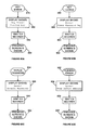
- FIG. 34 illustrates a dry run detection operation of the controller 75 .
- the controller 75 determines, at step 428 , if the frequency output to the motor is greater than a frequency preset value (e.g., about 30 Hz). If so, a timer is reset (step 430 ) and the controller 75 reverts back to step 426 . If the frequency is under the frequency preset value, the controller 75 then determines, at step 432 , if the pressure is greater than a pressure preset value (e.g., about 10 PSI). If so, the timer is reset (step 430 ) and the controller 75 reverts back to step 426 .
- a pressure preset value e.g., about 10 PSI
- step 434 the timer is incremented (step 434 ) and the controller 75 determines if the timer has reached 15 seconds (step 436 ). If not, the controller 75 reverts back to step 426 . However, if the timer has reached 15 seconds, the controller 75 determines that a dry run has occurred and executes a dry run fault operation (step 438 ).
- the preset value in step 428 can be checked to ensure the motor 11 is operating at a normal operating frequency (e.g., above 30 Hz).
- FIG. 35 illustrates a dry run fault operation of the controller 75 .
- the controller 75 can proceed to step 440 if step 438 of FIG. 34 was reached. From step 440 , the controller 75 can check if a reset counter value is less than a set value (e.g., the value set under the number of resets parameter 320 of FIG. 26 ) at step 442 . If the reset counter is not less than the set value, the controller 75 can update a fault log(step 444 ), coast the motor to a stop and display a “Dry Run” fault message (step 446 ), so that the drive 10 is stopped (step 448 ).
- a set value e.g., the value set under the number of resets parameter 320 of FIG. 26
- the reset counter is incremented (step 450 ) and the fault log is updated (step 452 ).
- the controller 75 can then coast the motor to a stop and display a “Dry Run-Auto Restart Pending” fault message (step 454 ), then start a fault timer (step 456 ), and continuously check if the user has pressed the fault reset button 64 (step 458 ) or if a timer has exceeded a time value (step 460 ).
- the time value can be the auto reset delay parameter 318 (shown in FIG. 26 ) set by the user.
- step 458 If the user presses the fault reset button 64 , the controller 75 will proceed from step 458 to step 462 and clear the fault message displayed, then stop the drive 10 (step 448 ). If the timer exceeds the time value, the controller 75 will proceed from step 460 to step 464 and clear the fault message displayed, then restart the drive 10 in PID mode (step 466 ).
- FIG. 36 illustrates a jam fault operation of the controller 75 .
- the fault log is updated (step 470 ).
- the motor is coasted to a stop and a “Foreign Object Jam” fault message is displayed (step 472 ), then the drive 10 is stopped (step 474 ).
- FIG. 37 illustrates an overtemperature fault operation of the controller 75 .
- the controller 75 determines if the power module temperature is too high (step 478 ), for example, using the overheat prevention operation in FIG. 30 . If the power module temperature is not too high, the fault is cleared (step 480 ) and the controller 75 reverts back to step 476 . If the power module temperature is too high, the fault log is updated (step 482 ), the motor is coasted to a stop and a “Drive Temp—Auto Restart Pending” fault message is displayed (step 484 ), and a fault timer is incremented (step 486 ).
- the controller 75 then continuously determines if the user has pressed the fault reset button 64 (step 488 ) until the timer has been incremented past a value (step 490 ). If the user has pressed the fault reset button 64 or if the timer has incremented past the value, the controller 75 proceeds from step 488 or step 490 , respectively, to step 492 to check if the fault condition is still present. If the fault condition is still present, the controller 75 reverts back to step 486 . If the fault condition is not present, the controller 75 clears the fault (step 480 ) and reverts back to step 476 .
- the motor 11 and pump 12 combination can satisfy typical performance requirements as specified by the pump manufacturer while maintaining current under service factor amps as specified for the motor 11 . Performance can match that of a typical capacitor start/capacitor run control box for each motor HP offering. If the motor 11 performs outside of such specifications, the controller 75 can generate a fault and stop the motor 11 .
- FIG. 38 illustrates an overcurrent fault operation of the controller 75 .
- the controller 75 determines if there is a high current spike (step 496 ), for example, using the overcurrent prevention operation of FIG. 31 . If there is no high current spike, the fault is cleared (step 498 ) and the controller 75 reverts back to step 494 .
- the fault log is updated (step 500 ), the motor is coasted to a stop and a “Motor High Amps—Auto Restart Pending” fault message is displayed (step 502 ), and a fault timer is incremented (step 504 ).
- the controller 75 then continuously determines if the user has pressed the fault reset button 64 (step 506 ) until the timer has been incremented past a value (step 508 ). If the user has pressed the fault reset button 64 or if the timer has incremented past the value, the controller 75 proceeds from step 506 or step 508 , respectively, to step 510 to check if the fault condition is still present. If the fault condition is still present, the controller 75 reverts back to step 504 . If the fault condition is not present, the controller 75 clears the fault (step 498 ) and reverts back to step 494 .
- FIG. 39 illustrates an overvoltage fault operation of the controller 75 .
- the controller 75 determines if a maximum bus voltage has been exceeded (step 514 ). If the bus voltage has not exceeded the maximum value, the fault is cleared (step 516 ) and the controller 75 reverts back to step 512 . If the bus voltage has exceeded the maximum value, the fault log is updated (step 518 ), the motor is coasted to a stop and an “Over Voltage—Auto Restart Pending” fault message is displayed (step 520 ), and a fault timer is incremented (step 522 ).
- the controller 75 then continuously determines if the user has pressed the fault reset button 64 (step 524 ) until the timer has been incremented past a value (step 526 ). If the user has pressed the fault reset button 64 or if the timer has incremented past the value, the controller 75 proceeds from step 524 or step 526 , respectively, to step 528 to check if the fault condition is still present. If the fault condition is still present, the controller 75 reverts back to step 522 . If the fault condition is not present, the controller 75 clears the fault (step 516 ) and reverts back to step 512 .
- FIG. 40 illustrates an internal fault operation of the controller 75 .
- the controller 75 determines if any internal voltages are out of range (step 532 ). If the internal voltages are not out of range, the fault is cleared (step 534 ) and the controller 75 reverts back to step 530 . If the internal voltages are out of range, the fault log is updated (step 536 ), the motor is coasted to a stop and an “Internal Fault—Auto Restart Pending” fault message is displayed (step 538 ), and a fault timer is incremented (step 540 ).
- the controller 75 then continuously determines if the user has pressed the fault reset button 64 (step 542 ) until the timer has been incremented past a value (step 544 ). If the user has pressed the fault reset button 64 or if the timer has incremented past the value, the controller 75 proceeds from step 542 or step 544 , respectively, to step 546 to check if the fault condition is still present. If the fault condition is still present, the controller 75 reverts back to step 540 . If the fault condition is not present, the controller 75 clears the fault (step 534 ) and reverts back to step 530 .
- FIG. 41 illustrates a ground fault operation of the controller 75 .
- the controller 75 continuously determines if there is current flow between an earth, or ground, lead and any motor lead (step 550 ). If so, the fault log is updated (step 552 ), the motor is coasted to a stop and a “Ground Fault” fault message is displayed (step 554 ), and the drive 10 is stopped (step 556 ).
- FIG. 42 illustrates an open transducer fault operation of the controller 75 .
- the controller 75 determines if a current measured at the transducer input is less than a value, such as 2 milliamps (step 560 ). If the current is not less than the value, the controller 75 reverts back to step 558 . If the current is less than the value, the fault log is updated (step 562 ), the motor is coasted to a stop and an “Open Transducer—Auto Restart Pending” fault message is displayed (step 564 ), and a fault timer is incremented (step 566 ).
- the controller 75 then continuously determines if the user has pressed the fault reset button 64 (step 568 ) until the timer has been incremented past a value (step 570 ). If the user has pressed the fault reset button 64 or if the timer has incremented past the value, the controller 75 proceeds from step 568 or step 570 , respectively, to step 572 to check if the fault condition is still present. If the fault condition is still present, the controller 75 reverts back to step 566 . If the fault condition is not present, the controller 75 reverts back to step 558 .
- FIG. 43 illustrates a shorted transducer fault operation of the controller 75 .
- the controller 75 determines if a current measured at the transducer input is greater than a value, such as 25 milliamps (step 576 ). If the current is not greater than the value, the controller 75 reverts back to step 574 . If the current is greater than the value, the fault log is updated (step 578 ), the motor is coasted to a stop and a “Shorted Transducer—Auto Restart Pending” fault message is displayed (step 580 ), and a fault timer is incremented (step 582 ).
- the controller 75 then continuously determines if the user has pressed the fault reset button 64 (step 586 ) until the timer has been incremented past a value (step 588 ). If the user has pressed the fault reset button 64 or if the timer has incremented past the value, the controller 75 proceeds from step 586 or step 588 , respectively, to step 590 to check if the fault condition is still present. If the fault condition is still present, the controller 75 reverts back to step 582 . If the fault condition is not present, the controller 75 reverts back to step 574 .
- FIGS. 44A-44B illustrate a multiple faults operation of the controller 75 .
- the controller 75 continuously determines if a fault has occurred (step 594 ). If a fault has a occurred, a counter is incremented (step 596 ) and the controller 75 determines if the counter has reached a value, such as ten (step 598 ). If the counter has reached the value, the motor is coasted to a stop and a “Multiple Faults” fault message is displayed (step 600 ), and the drive 10 is stopped (step 602 ).
- the steps of FIG. 44B serve to provide a time frame for which the counter can reach the value.
- the controller 75 continuously determines if the counter (i.e., the counter in step 596 of FIG. 44A ) has been incremented (step 604 ). If so, a timer is incremented (step 606 ). The controller 75 continues to increment the timer as long as the counter is above zero until the timer reaches a value, such as thirty minutes (step 608 ). Once the timer has reached the value, the counter is decremented and the timer is reset (step 610 ).
- the counter i.e., the counter in step 596 of FIG. 44A
- FIG. 45 illustrates an undervoltage fault operation of the controller 75 .
- the controller 75 determines if the bus voltage is below a minimum value (step 614 ). If the bus voltage is not below the minimum value, the fault is cleared (step 616 ) and the controller 75 reverts back to step 612 .
- the fault log is updated (step 618 ), the motor is coasted to a stop and an “Under Voltage—Auto Restart Pending” fault message is displayed (step 620 ), the fault log is saved in memory, such as the device's electrically erasable programmable read-only memory, or EEPROM (step 622 ) and a fault timer is incremented (step 624 ).
- the controller 75 then continuously determines if the user has pressed the fault reset button 64 (step 626 ) until the timer has been incremented past a value (step 628 ).
- step 626 or step 628 the controller 75 proceeds from step 626 or step 628 , respectively, to step 630 to check if the fault condition is still present. If the fault condition is still present, the controller 75 reverts back to step 624 . If the fault condition is not present, the controller 75 clears the fault (step 616 ) and reverts back to step 612 .
- FIG. 46 illustrates a hardware fault operation of the controller 75 .
- the controller 75 recognizes a hardware error (step 632 )
- the fault log is updated (step 634 ).
- the motor is coasted to a stop and a “Hardware Error” fault message is displayed (step 636 ), then the drive 10 is stopped (step 638 ).
- FIG. 47 illustrates an external fault operation of the controller 75 .
- the controller 75 continuously determines if an external fault parameter is present, for example, from a relay input at the input power terminal block 28 or the digital input/output (I/O) spring terminals 30 (step 642 ). If so, the controller 75 determines if a digital input is high (step 644 ). If the digital input is not high, the controller 75 determines if the external fault is active (step 646 ). If the external fault is not active, the controller 75 reverts back to step 640 .
- an external fault parameter for example, from a relay input at the input power terminal block 28 or the digital input/output (I/O) spring terminals 30 (step 642 ). If so, the controller 75 determines if a digital input is high (step 644 ). If the digital input is not high, the controller 75 determines if the external fault is active (step 646 ). If the external fault is not active, the controller 75 reverts back to step 640 .
- the controller 75 clears an “external fault” fault message (if it is being displayed) at step 648 and the device's previous state and operation are restored (step 650 ). If, at step 644 , the digital input is high, the fault log is updated (step 652 ) and the device's current state and operation are saved (step 654 ). Following step 654 , the motor is coasted to a stop and a “External Fault” fault message is displayed (step 656 ), then the drive 10 is stopped (step 658 ).
- FIGS. 48-63 are flow charts describing control operations for the control pad 14 according to some embodiments of the invention.
- FIG. 48 illustrates a pump-out button control operation, according to some embodiments.
- the controller 75 first determines if the control pad 14 is locked, or in the password protection mode (step 662 ). If so, the controller 75 executes a keys locked error operation (step 664 ). If not, a valve screen 666 is displayed (step 668 ) asking the user if a valve is open. Once the user chooses if the valve is open or not and presses enter, a valve parameter value is changed (step 670 ).
- the controller 75 determines, at step 672 , if the valve parameter value is yes (i.e., if the valve is open). If the valve parameter is not yes (i.e., if the user selected that the valve was not open), a stopped screen is displayed (step 674 ), indicating that the pump 12 is stopped. If the valve parameter is yes, the controller 75 sets LED indicators 66 on or off accordingly (step 676 ), displays a status screen 678 (step 680 ), and runs the pump out operation to drive the motor 11 in the pump out mode (step 682 ).
- the status screen 678 can include information about the pump 12 , such as motor frequency, pressure, and motor current during the pump out mode.
- FIG. 49 illustrates a pressure preset button control operation, according to some embodiments.
- the controller 75 first determines if the control pad 14 is locked (step 686 ). If so, the controller 75 executes a keys locked error operation (step 688 ). If the control pad 14 is not locked, the controller 75 sets the LED indicators 66 on or off accordingly (step 690 ) and a preset pressure parameter is displayed (step 692 ). The user can adjust the displayed pressure parameter using the keypad and hit enter to change the value of the preset pressure parameter, changing the pressure set point for the controller 75 (step 694 ).
- FIG. 50 illustrates a main menu button control operation, according to some embodiments.
- the controller 75 first determines if the control pad 14 is locked (step 698 ). If so, the controller 75 executes a keys locked error operation (step 700 ). If the control pad 14 is not locked, the controller 75 sets the LED indicators 66 on or off accordingly (step 702 ) and the main menu, as described with respect to FIG. 16 , is displayed (step 704 ).
- FIG. 51 illustrates a fault log button control operation, according to some embodiments.
- the controller 75 sets the LED indicators 66 on or off accordingly (step 708 ) and the fault log is displayed, detailing fault history information to the user (step 710 ).
- FIG. 52 illustrates an enter button control operation, according to some embodiments.
- the controller 75 first determines if the fault log is active (e.g., being displayed) at step 714 or if the stopped status screen is being displayed (step 716 ). If either step 714 or step 716 is true, the controller 75 executes an invalid key error operation (step 718 ). If neither the fault log or stopped status screen are being displayed, the controller 75 determines if the control pad 14 is locked (step 720 ). If so, the controller 75 executes a keys locked error operation (step 722 ). If the control pad 14 is not locked, the controller 75 determines if the display currently selecting a menu option or a parameter (step 724 ).
- the controller 75 will enter the selected menu (step 726 ). If the display is currently selecting a parameter option, the controller 75 determines if the parameter is highlighted (step 728 ). If the parameter is highlighted, the controller 75 saves the value of the selected parameter and cancels the highlighting of the parameter (step 730 ). If, at step 728 , the parameter is not highlighted, the controller 75 determines if the parameter can be changed with the motor is running and the drive 10 is stopped (step 732 ). If not, a running error operation is executed (step 734 ). If the parameter may be changed, then the selected parameter is highlighted (step 736 ).
- FIG. 53 illustrates a back button control operation, according to some embodiments.
- the controller 75 determines if a status screen is being displayed (step 740 ). If so, an invalid key error operation is executed (step 742 ). If a status screen is not being displayed, the controller 75 determines if a line in the display is highlighted (step 744 ). If so, the new value on the highlighted line is cancelled and the highlighting is cancelled as well (step 746 ). If, at step 744 , there is no highlighted line, the parent, or previous, menu is displayed (step 748 ).
- FIG. 54 illustrates an up/down button control operation, according to some embodiments.
- the controller 75 determines if a line in the display is highlighted (step 752 ). If so, the controller 75 then determines if the auto line fill operation is being executed (step 754 ). If so, the controller 75 proceeds to the manual line fill operation (step 756 ), as described with reference to FIG. 9 , then scrolls to another value in the display (step 758 ). If the controller 75 determines that the auto line fill operation is not being executed at step 754 , the controller 75 proceeds to step 758 and scrolls to another value in the display.
- step 752 determines that no line is highlighted, the controller 75 then determines if a menu in the display can be scrolled (step 760 ). If so, the menu is scrolled (step 762 ). If not, an invalid key error operation is executed (step 764 ).
- FIG. 55 illustrates a left/right button control operation, according to some embodiments.
- the controller 75 determines if a line in the display is highlighted (step 768 ). If not, an invalid key error operation is executed (step 770 ). If, at step 768 , the controller 75 determines that the line is highlighted, the controller 75 then determines if a curser in the display can be moved (step 772 ). If so, the curser is moved (step 774 ). If not, an invalid key error operation is executed (step 776 ).
- FIG. 56 illustrates a password button control operation, according to some embodiments.
- the controller 75 first determines if the control pad 14 is locked (step 780 ). If not, a status screen is displayed (step 782 ). If the control pad 14 is locked, the controller 75 sets the LED indicators 66 on or off accordingly (step 784 ) and executes a keys locked error operation (step 786 ). If a user then enters a password (step 788 ), the controller 75 determines if the password is correct (step 790 ). If the password is correct, any lockable keys are unlocked (step 792 ) and the status screen is displayed (step 794 ).
- the lockable keys can include the directional buttons 52 , the language button 50 , the pump-out button 40 , the pressure preset button 42 , and/or the main menu button 44 .
- FIG. 57 illustrates a language button control operation, according to some embodiments.
- the controller 75 first determines if the control pad 14 is locked (step 798 ). If so, the controller 75 executes a keys locked error operation (step 800 ). If the control pad 14 is not locked, the controller 75 sets the LED indicators 66 on or off accordingly (step 802 ) and a language parameter is displayed (step 804 ). The user can change the displayed language using the keypad and hit enter to update the language parameter (step 806 ).
- FIG. 58 illustrates a status button control operation, according to some embodiments.
- the controller 75 sets the LED indicators 66 on or off accordingly (step 810 ) and determines if a current status screen is being displayed (step 812 ). If not, the current status screen 814 or 816 is displayed (step 818 ). If the controller 75 , at step 812 , determines that the current status screen is being displayed, the currents status screen is cleared and a power status screen 820 or 822 is displayed (step 824 ).
- FIG. 59 illustrates a stop button control operation, according to some embodiments.
- the controller 75 sets the LED indicators 66 on or off accordingly (step 828 ) and a stopped status screen 830 is displayed (step 832 ).
- the controller 75 then stops the drive 10 (step 834 ), as described with reference to FIG. 10 .
- FIG. 60 illustrates an automatic start button control operation, according to some embodiments.
- the controller 75 sets the LED indicators 66 on or off accordingly (step 838 ) and a status screen 840 is displayed (step 842 ).
- the controller 75 then runs the automatic line fill operation (step 844 ), as described with reference to FIG. 8 .
- FIG. 61 illustrates a fault reset button control operation, according to some embodiments.
- the controller 75 determines if there is an active fault (step 848 ). If not, the controller 75 executes an invalid key error operation (step 850 ). If there is an active fault, the controller 75 determines if the fault condition is still present (step 852 ). If so, the controller 75 stops the drive 10 (step 854 ), as described with reference to FIG. 10 . If not, the controller 75 first clears the fault (step 856 ), then stops the drive 10 (step 854 ).
- FIGS. 62A-62D illustrate LED indicator control operations, according to some embodiments.
- FIG. 62A if a fault is active and a restart is pending (step 856 ), the Fault LED 72 blinks (step 858 ), and a “Restart Pending” message is displayed (step 860 ).
- FIG. 62B if a fault is active and the drive 10 is stopped (step 862 ), the Fault LED 72 blinks (step 864 ), and a “Drive Stopped” message is displayed (step 866 ). As shown in FIG.
- step 868 if a TPM is active and the drive 10 is still running (step 868 ), the Warning LED 70 is lit (step 870 ), and a message is displayed describing the warning (step 872 ). As shown in FIG. 62D , when the drive 10 is powered up (step 874 ), the ON LED 68 is lit (step 876 ).
- FIGS. 63A-63D illustrate error display control operations, according to some embodiments.
- a “Key Error! Invalid Key!” error screen can be displayed (step 880 ).
- the controller 75 can display the error screen for a time period, such as 0.9 seconds (step 882 ), then return the display to the previous screen (step 884 ).
- an “Error! Press Password Key” error screen can be displayed (step 888 ).
- the controller 75 can display the error screen for a time period, such as 0.9 seconds (step 890 ), then return the display to the previous screen (step 892 ).
- an “Error! Invalid Password!” error screen can be displayed (step 896 ).
- the controller 75 can display the error screen for a time period, such as 0.9 seconds (step 898 ), then return the display to the previous screen (step 900 ).
- an “Error! Stop before editing” error screen can be displayed (step 904 ).
- the controller 75 can display the error screen for a time period, such as 0.9 seconds (step 906 ), then return the display to the previous screen (step 908 ).
Landscapes
- Engineering & Computer Science (AREA)
- Mechanical Engineering (AREA)
- General Engineering & Computer Science (AREA)
- Computer Hardware Design (AREA)
- Physics & Mathematics (AREA)
- General Physics & Mathematics (AREA)
- Control Of Electric Motors In General (AREA)
- Control Of Positive-Displacement Pumps (AREA)
- Control Of Ac Motors In General (AREA)
Abstract
Description
Claims (17)
Priority Applications (7)
| Application Number | Priority Date | Filing Date | Title |
|---|---|---|---|
| US12/481,475 US8436559B2 (en) | 2009-06-09 | 2009-06-09 | System and method for motor drive control pad and drive terminals |
| CA2707167A CA2707167C (en) | 2009-06-09 | 2010-06-08 | System and method for motor drive control pad and drive terminals |
| EP10165386.3A EP2273116A3 (en) | 2009-06-09 | 2010-06-09 | System and method for motor drive control pad and drive terminals |
| MX2010006357A MX2010006357A (en) | 2009-06-09 | 2010-06-09 | System and method for motor drive control pad and drive terminals. |
| AU2010202411A AU2010202411B2 (en) | 2009-06-09 | 2010-06-09 | System and method for motor drive control pad and drive terminals |
| CN201010241942.0A CN102003374B (en) | 2009-06-09 | 2010-06-09 | System and method for motor drive control pad and drive terminals |
| US13/889,140 US8878465B2 (en) | 2009-06-09 | 2013-05-07 | System and method for motor drive control pad and drive terminals |
Applications Claiming Priority (1)
| Application Number | Priority Date | Filing Date | Title |
|---|---|---|---|
| US12/481,475 US8436559B2 (en) | 2009-06-09 | 2009-06-09 | System and method for motor drive control pad and drive terminals |
Related Child Applications (1)
| Application Number | Title | Priority Date | Filing Date |
|---|---|---|---|
| US13/889,140 Division US8878465B2 (en) | 2009-06-09 | 2013-05-07 | System and method for motor drive control pad and drive terminals |
Publications (2)
| Publication Number | Publication Date |
|---|---|
| US20100308963A1 US20100308963A1 (en) | 2010-12-09 |
| US8436559B2 true US8436559B2 (en) | 2013-05-07 |
Family
ID=42735454
Family Applications (2)
| Application Number | Title | Priority Date | Filing Date |
|---|---|---|---|
| US12/481,475 Active 2031-07-20 US8436559B2 (en) | 2009-06-09 | 2009-06-09 | System and method for motor drive control pad and drive terminals |
| US13/889,140 Active US8878465B2 (en) | 2009-06-09 | 2013-05-07 | System and method for motor drive control pad and drive terminals |
Family Applications After (1)
| Application Number | Title | Priority Date | Filing Date |
|---|---|---|---|
| US13/889,140 Active US8878465B2 (en) | 2009-06-09 | 2013-05-07 | System and method for motor drive control pad and drive terminals |
Country Status (6)
| Country | Link |
|---|---|
| US (2) | US8436559B2 (en) |
| EP (1) | EP2273116A3 (en) |
| CN (1) | CN102003374B (en) |
| AU (1) | AU2010202411B2 (en) |
| CA (1) | CA2707167C (en) |
| MX (1) | MX2010006357A (en) |
Cited By (31)
| Publication number | Priority date | Publication date | Assignee | Title |
|---|---|---|---|---|
| US20140229023A1 (en) * | 2011-09-20 | 2014-08-14 | Grundfos Holding A/S | Pump unit |
| US20140368152A1 (en) * | 2013-03-15 | 2014-12-18 | Micheal Robert Pasche | Method of Controlling a Pump and Motor |
| USD741815S1 (en) * | 2014-03-31 | 2015-10-27 | Beacon Technical Systems, Llc | Sump pump monitor |
| USD742333S1 (en) * | 2014-02-17 | 2015-11-03 | Abb Technology Ltd | Human machine interface for a softstarter |
| USD748065S1 (en) * | 2014-08-26 | 2016-01-26 | Ingersoll-Rand Company | Controller |
| USD750572S1 (en) * | 2014-12-11 | 2016-03-01 | Gizmode, LLC | Control panel |
| US20160156303A1 (en) * | 2011-05-17 | 2016-06-02 | Graham McIvor | Control Device and Pump Apparatus |
| US9404501B2 (en) | 2013-11-26 | 2016-08-02 | Beacon Technical Systems, Llc | Sump pump test and monitoring system |
| US9523366B2 (en) | 2013-11-26 | 2016-12-20 | Beacon Technical Systems, Llc | Test and monitoring system for a sump pump installation having a self-protecting valve assembly for admitting water to the sump container |
| US9525309B2 (en) | 2013-11-26 | 2016-12-20 | Beacon Technical Systems, Llc | Battery-powered backup power system for a sump pump installation |
| US9528520B2 (en) | 2013-11-26 | 2016-12-27 | Beacon Technical Systems, Llc | Test and monitoring system for a dual sump pump system |
| US9528523B2 (en) | 2013-11-26 | 2016-12-27 | Beacon Technical Systems, Llc | Test and monitoring system for a sump pump installation having a variable test cycle time out |
| US9528873B2 (en) | 2013-11-26 | 2016-12-27 | Beacon Technical Systems, Llc | Test and monitoring system for a sump pump installation having a self-monitoring liquid level sensing module |
| US9528522B2 (en) | 2013-11-26 | 2016-12-27 | Beacon Technical Systems, Llc | Test and monitoring system for a sump pump installation having a self-monitoring valve module for admitting water to the sump pit |
| US9528512B2 (en) | 2013-11-26 | 2016-12-27 | Beacon Technical Systems, Llc | Test and monitoring system for a battery-powered DC pump installation |
| US9534606B2 (en) | 2013-11-26 | 2017-01-03 | Beacon Technical Systems, Llc | Test and monitoring system for a sump pump installation including trend analysis of pump performance |
| US9534593B2 (en) | 2013-11-26 | 2017-01-03 | Beacon Technical Systems, Llc | Test and monitoring system for a sump pump installation operable from a remote location |
| US9670918B2 (en) | 2013-04-12 | 2017-06-06 | Pentair Flow Technologies, Llc | Water booster control system and method |
| USD794076S1 (en) * | 2016-09-09 | 2017-08-08 | Yehuda Goltche | Control pad |
| USD794579S1 (en) * | 2016-07-09 | 2017-08-15 | Liberty Pumps, Inc. | Display panel |
| US9932806B2 (en) | 2014-04-28 | 2018-04-03 | Summit Esp, Llc | Apparatus, system and method for reducing gas to liquid ratios in submersible pump applications |
| US20180249595A1 (en) * | 2017-02-24 | 2018-08-30 | Summit Esp, Llc | Variable frequency drive cabinet ventilation system, apparatus and method |
| USD840355S1 (en) * | 2017-05-24 | 2019-02-12 | Interroll Holding Ag | Front panel soft starter |
| US10208747B2 (en) | 2016-02-09 | 2019-02-19 | Beacon Technical Systems, Llc | Trap for pump testing and monitoring systems |
| US10296016B1 (en) | 2013-07-10 | 2019-05-21 | Taco, Inc. | Self-limiting pump-motor-VFD combination |
| US10393122B2 (en) * | 2014-06-17 | 2019-08-27 | Xylem Europe Gmbh | Method for shutting off a pump as well as pump station arrangement |
| USD881140S1 (en) * | 2018-03-30 | 2020-04-14 | Siemens Aktiengesellschaft | Control box |
| US10865787B2 (en) | 2016-12-06 | 2020-12-15 | Pentair Flow Technologies, Llc | Connected pump system controller and method of use |
| US11018610B2 (en) | 2017-01-27 | 2021-05-25 | Franklin Electric Co., Inc. | Motor drive system and method |
| US11234380B2 (en) | 2018-09-27 | 2022-02-01 | Rain Bird Corporation | Irrigation controller with relays |
| US11357181B2 (en) | 2020-02-12 | 2022-06-14 | Rain Bird Corporation | Data modulated signal generation in a multi-wire irrigation control system |
Families Citing this family (10)
| Publication number | Priority date | Publication date | Assignee | Title |
|---|---|---|---|---|
| WO2011106530A1 (en) * | 2010-02-25 | 2011-09-01 | Hayward Industries, Inc. | Universal mount for a variable speed pump drive user interface |
| RU2550181C2 (en) * | 2010-03-18 | 2015-05-10 | Грако Миннесота Инк. | Remote control over pump operating rate |
| US9528524B2 (en) * | 2011-10-31 | 2016-12-27 | Regal Beloit America, Inc. | Pump freeze protection |
| BR112014010665A2 (en) | 2011-11-01 | 2017-12-05 | Pentair Water Pool & Spa Inc | flow blocking system and process |
| US9115013B2 (en) * | 2012-08-15 | 2015-08-25 | Green Age Technologies Llc | Fluid filtration system |
| US11105323B2 (en) * | 2016-10-21 | 2021-08-31 | Franklin Electric Co., Inc. | Motor drive system and method |
| DE102017002342A1 (en) | 2017-03-13 | 2018-09-13 | Wilo Se | Configuration procedure for a variable-speed centrifugal pump assembly and associated configuration wizard |
| AU2019236622B1 (en) * | 2019-06-06 | 2019-11-28 | Allied Pumps Pty Ltd | Control system |
| US11768929B2 (en) | 2019-09-04 | 2023-09-26 | Blue-White Industries, Ltd. | Lockout system for metering pump |
| CN111045418B (en) * | 2019-12-27 | 2021-09-28 | 中国科学院电工研究所 | Health management system of electric drive system |
Citations (321)
| Publication number | Priority date | Publication date | Assignee | Title |
|---|---|---|---|---|
| US1061919A (en) | 1912-09-19 | 1913-05-13 | Clifford G Miller | Magnetic switch. |
| US2238597A (en) | 1939-08-24 | 1941-04-15 | Chicago Pump Co | Pumping apparatus |
| US2458006A (en) | 1946-10-24 | 1949-01-04 | Westinghouse Electric Corp | Bidirectional blower |
| US2488365A (en) | 1947-01-15 | 1949-11-15 | Westinghouse Electric Corp | All-around motor ventilation |
| US2494200A (en) | 1946-02-12 | 1950-01-10 | Ramqvist Nils Allan | Electric machine |
| US2615937A (en) | 1946-08-15 | 1952-10-28 | Westinghouse Electric Corp | Fan-cooled motor |
| US2716195A (en) | 1952-12-26 | 1955-08-23 | Fairbanks Morse & Co | Ventilation of electric machines |
| US2767277A (en) | 1952-12-04 | 1956-10-16 | James F Wirth | Control system for power operated fluid pumps |
| US2778958A (en) | 1954-10-28 | 1957-01-22 | Gen Electric | Dynamoelectric machine |
| US2881337A (en) | 1957-07-01 | 1959-04-07 | Gen Electric | Acoustically treated motor |
| US3191935A (en) | 1962-07-02 | 1965-06-29 | Brunswick Corp | Pin detection means including electrically conductive and magnetically responsive circuit closing particles |
| US3213304A (en) | 1962-11-06 | 1965-10-19 | Allis Chalmers Mfg Co | Fan-cooled electric motor |
| US3291058A (en) | 1965-04-16 | 1966-12-13 | Gorman Rupp Co | Quick priming centrifugal pump |
| US3558910A (en) | 1968-07-19 | 1971-01-26 | Motorola Inc | Relay circuits employing a triac to prevent arcing |
| US3581895A (en) | 1969-02-28 | 1971-06-01 | Herbert H Howard | Automatic backwashing filter system for swimming pools |
| US3613805A (en) | 1969-09-03 | 1971-10-19 | Bucyrus Erie Co | Automatic control for rotary drill |
| US3737749A (en) | 1972-06-16 | 1973-06-05 | Electronic Flag Poles Inc | Motor control system |
| US3778804A (en) | 1971-12-06 | 1973-12-11 | L Adair | Swimming pool user warning system |
| US3787882A (en) | 1972-09-25 | 1974-01-22 | Ibm | Servo control of ink jet pump |
| US3838597A (en) | 1971-12-28 | 1974-10-01 | Mobil Oil Corp | Method and apparatus for monitoring well pumping units |
| US3949782A (en) | 1973-04-05 | 1976-04-13 | Hobart Corporation | Control circuit for dishwasher |
| US3953777A (en) | 1973-02-12 | 1976-04-27 | Delta-X Corporation | Control circuit for shutting off the electrical power to a liquid well pump |
| US3963375A (en) | 1974-03-12 | 1976-06-15 | Curtis George C | Time delayed shut-down circuit for recirculation pump |
| US4021700A (en) | 1975-06-04 | 1977-05-03 | Borg-Warner Corporation | Digital logic control system for three-phase submersible pump motor |
| US4041470A (en) | 1976-01-16 | 1977-08-09 | Industrial Solid State Controls, Inc. | Fault monitoring and reporting system for trains |
| US4123792A (en) | 1977-04-07 | 1978-10-31 | Gephart Don A | Circuit for monitoring the mechanical power from an induction motor and for detecting excessive heat exchanger icing |
| US4133058A (en) | 1976-03-02 | 1979-01-09 | Baker William H | Automated pool level and skimming gutter flow control system |
| US4151080A (en) | 1978-02-13 | 1979-04-24 | Enviro Development Co., Inc. | System and apparatus for control and optimization of filtration process |
| US4168413A (en) | 1978-03-13 | 1979-09-18 | Halpine Joseph C | Piston detector switch |
| US4241299A (en) | 1979-04-06 | 1980-12-23 | Mine Safety Appliances Company | Control system for battery-operated pump |
| US4263535A (en) | 1978-09-29 | 1981-04-21 | Bucyrus-Erie Company | Motor drive system for an electric mining shovel |
| US4286303A (en) | 1979-03-19 | 1981-08-25 | Franklin Electric Co., Inc. | Protection system for an electric motor |
| US4319712A (en) | 1980-04-28 | 1982-03-16 | Ofer Bar | Energy utilization reduction devices |
| US4322297A (en) | 1980-08-18 | 1982-03-30 | Peter Bajka | Controller and control method for a pool system |
| US4353220A (en) | 1980-06-17 | 1982-10-12 | Mechanical Technology Incorporated | Resonant piston compressor having improved stroke control for load-following electric heat pumps and the like |
| US4370098A (en) | 1980-10-20 | 1983-01-25 | Esco Manufacturing Company | Method and apparatus for monitoring and controlling on line dynamic operating conditions |
| US4402094A (en) | 1982-03-18 | 1983-09-06 | Sanders John T | Safety circulation system |
| US4419625A (en) | 1980-12-05 | 1983-12-06 | La Telemecanique Electrique | Determining asynchronous motor couple |
| US4420787A (en) | 1981-12-03 | 1983-12-13 | Spring Valley Associates Inc. | Water pump protector |
| US4449260A (en) | 1982-09-01 | 1984-05-22 | Whitaker Brackston T | Swimming pool cleaning method and apparatus |
| US4462758A (en) | 1983-01-12 | 1984-07-31 | Franklin Electric Co., Inc. | Water well pump control assembly |
| US4473338A (en) | 1980-09-15 | 1984-09-25 | Garmong Victor H | Controlled well pump and method of analyzing well production |
| US4494180A (en) | 1983-12-02 | 1985-01-15 | Franklin Electric Co., Inc. | Electrical power matching system |
| US4504773A (en) | 1981-09-10 | 1985-03-12 | Kureha Kagaku Kogyo Kabushiki Kaisha | Capacitor discharge circuit |
| US4505643A (en) | 1983-03-18 | 1985-03-19 | North Coast Systems, Inc. | Liquid pump control |
| US4541029A (en) | 1982-10-06 | 1985-09-10 | Tsubakimoto Chain Co. | Over-load and light-load protection for electric machinery |
| US4610605A (en) | 1985-06-25 | 1986-09-09 | Product Research And Development | Triple discharge pump |
| US4620835A (en) | 1983-06-02 | 1986-11-04 | American Standard Inc. | Pump protection system |
| US4635441A (en) | 1985-05-07 | 1987-01-13 | Sundstrand Corporation | Power drive unit and control system therefor |
| US4647825A (en) | 1985-02-25 | 1987-03-03 | Square D Company | Up-to-speed enable for jam under load and phase loss |
| US4676914A (en) | 1983-03-18 | 1987-06-30 | North Coast Systems, Inc. | Microprocessor based pump controller for backwashable filter |
| US4678409A (en) | 1984-11-22 | 1987-07-07 | Fuji Photo Film Co., Ltd. | Multiple magnetic pump system |
| US4678404A (en) | 1983-10-28 | 1987-07-07 | Hughes Tool Company | Low volume variable rpm submersible well pump |
| US4686439A (en) | 1985-09-10 | 1987-08-11 | A. T. Hunn Company | Multiple speed pump electronic control system |
| US4695779A (en) | 1986-05-19 | 1987-09-22 | Sargent Oil Well Equipment Company Of Dover Resources, Incorporated | Motor protection system and process |
| US4703387A (en) | 1986-05-22 | 1987-10-27 | Franklin Electric Co., Inc. | Electric motor underload protection system |
| US4758697A (en) | 1983-11-04 | 1988-07-19 | Societe Internationale de Promotion Commerciale | Intermittent supply control device for electric appliances of in particular a hotel room |
| US4767280A (en) | 1987-08-26 | 1988-08-30 | Markuson Neil D | Computerized controller with service display panel for an oil well pumping motor |
| US4780050A (en) | 1985-12-23 | 1988-10-25 | Sundstrand Corporation | Self-priming pump system |
| US4795314A (en) | 1987-08-24 | 1989-01-03 | Cobe Laboratories, Inc. | Condition responsive pump control utilizing integrated, commanded, and sensed flowrate signals |
| US4834624A (en) | 1986-12-13 | 1989-05-30 | Grundfos International A/S | Pump assembly for delivering liquids and gases |
| US4837656A (en) | 1987-02-27 | 1989-06-06 | Barnes Austen Bernard | Malfunction detector |
| US4841404A (en) | 1987-10-07 | 1989-06-20 | Spring Valley Associates, Inc. | Pump and electric motor protector |
| US4864287A (en) | 1983-07-11 | 1989-09-05 | Square D Company | Apparatus and method for calibrating a motor monitor by reading and storing a desired value of the power factor |
| US4885655A (en) | 1987-10-07 | 1989-12-05 | Spring Valley Associates, Inc. | Water pump protector unit |
| FR2529965B1 (en) | 1982-07-06 | 1989-12-22 | Grundfos As | MOTOR-PUMP GROUP WITH SPEED ADJUSTMENT |
| US4891569A (en) | 1982-08-20 | 1990-01-02 | Versatex Industries | Power factor controller |
| US4907610A (en) | 1986-08-15 | 1990-03-13 | Crystal Pools, Inc. | Cleaning system for swimming pools and the like |
| US4912936A (en) | 1987-04-11 | 1990-04-03 | Kabushiki Kaisha Toshiba | Refrigeration control system and method |
| US4913625A (en) | 1987-12-18 | 1990-04-03 | Westinghouse Electric Corp. | Automatic pump protection system |
| EP0314249A3 (en) | 1987-10-28 | 1990-05-30 | Shell Internationale Researchmaatschappij B.V. | Pump off/gas lock motor controller for electrical submersible pumps |
| US4963778A (en) | 1986-12-13 | 1990-10-16 | Grundfos International A/S | Frequency converter for controlling a motor |
| US4971522A (en) | 1989-05-11 | 1990-11-20 | Butlin Duncan M | Control system and method for AC motor driven cyclic load |
| US4977394A (en) | 1989-11-06 | 1990-12-11 | Whirlpool Corporation | Diagnostic system for an automatic appliance |
| US4996646A (en) | 1988-03-31 | 1991-02-26 | Square D Company | Microprocessor-controlled circuit breaker and system |
| US4998097A (en) | 1983-07-11 | 1991-03-05 | Square D Company | Mechanically operated pressure switch having solid state components |
| US5026256A (en) | 1987-12-18 | 1991-06-25 | Hitachi, Ltd. | Variable speed pumping-up system |
| US5076761A (en) | 1990-06-26 | 1991-12-31 | Graco Inc. | Safety drive circuit for pump motor |
| US5076763A (en) | 1984-12-31 | 1991-12-31 | Rule Industries, Inc. | Pump control responsive to timer, delay circuit and motor current |
| US5079784A (en) | 1989-02-03 | 1992-01-14 | Hydr-O-Dynamic Systems, Inc. | Hydro-massage tub control system |
| US5099181A (en) | 1991-05-03 | 1992-03-24 | Canon K N Hsu | Pulse-width modulation speed controllable DC brushless cooling fan |
| US5100298A (en) | 1989-03-07 | 1992-03-31 | Ebara Corporation | Controller for underwater pump |
| USRE33874E (en) | 1986-05-22 | 1992-04-07 | Franklin Electric Co., Inc. | Electric motor load sensing system |
| US5117233A (en) | 1990-10-18 | 1992-05-26 | Teledyne Industries, Inc. | Spa and swimming pool remote control systems |
| US5123080A (en) | 1987-03-20 | 1992-06-16 | Ranco Incorporated Of Delaware | Compressor drive system |
| US5151017A (en) | 1991-05-15 | 1992-09-29 | Itt Corporation | Variable speed hydromassage pump control |
| US5156535A (en) | 1990-10-31 | 1992-10-20 | Itt Corporation | High speed whirlpool pump |
| US5158436A (en) | 1990-03-29 | 1992-10-27 | Grundfos International A/S | Pump with speed controller responsive to temperature |
| US5159713A (en) | 1985-11-27 | 1992-10-27 | Seiko Corp. | Watch pager and wrist antenna |
| US5167041A (en) | 1990-06-20 | 1992-12-01 | Kdi American Products, Inc. | Suction fitting with pump control device |
| US5172089A (en) | 1991-06-14 | 1992-12-15 | Wright Jane F | Pool pump fail safe switch |
| US5240380A (en) | 1991-05-21 | 1993-08-31 | Sundstrand Corporation | Variable speed control for centrifugal pumps |
| US5295857A (en) * | 1992-12-23 | 1994-03-22 | Toly Elde V | Electrical connector with improved wire termination system |
| US5324170A (en) | 1984-12-31 | 1994-06-28 | Rule Industries, Inc. | Pump control apparatus and method |
| US5327036A (en) | 1993-01-19 | 1994-07-05 | General Electric Company | Snap-on fan cover for an electric motor |
| US5342176A (en) | 1993-04-05 | 1994-08-30 | Sunpower, Inc. | Method and apparatus for measuring piston position in a free piston compressor |
| US5418984A (en) | 1993-06-28 | 1995-05-30 | Plastic Development Company - Pdc | Hydrotherapy seat structure for a hydrotherapy spa, tub or swimming pool |
| FR2703409B1 (en) | 1993-04-02 | 1995-06-02 | Seim Ind | Bi-directional centrifugal pump. |
| US5471125A (en) | 1994-09-09 | 1995-11-28 | Danfoss A/S | AC/DC unity power-factor DC power supply for operating an electric motor |
| US5473497A (en) | 1993-02-05 | 1995-12-05 | Franklin Electric Co., Inc. | Electronic motor load sensing device |
| US5483229A (en) * | 1993-02-18 | 1996-01-09 | Yokogawa Electric Corporation | Input-output unit |
| US5499902A (en) | 1991-12-04 | 1996-03-19 | Environamics Corporation | Environmentally safe pump including seal |
| US5511397A (en) | 1993-04-28 | 1996-04-30 | Kabushiki Kaisha Toshiba | Washing machine with means for storing and displaying data of contents of washing operation |
| US5512883A (en) | 1992-11-03 | 1996-04-30 | Lane, Jr.; William E. | Method and device for monitoring the operation of a motor |
| EP0709575A1 (en) | 1994-10-05 | 1996-05-01 | FRANKLIN ELECTRIC Co., Inc. | Liquid supply system |
| US5518371A (en) | 1994-06-20 | 1996-05-21 | Wells, Inc. | Automatic fluid pressure maintaining system from a well |
| US5519848A (en) | 1993-11-18 | 1996-05-21 | Motorola, Inc. | Method of cell characterization in a distributed simulation system |
| US5520517A (en) | 1993-06-01 | 1996-05-28 | Sipin; Anatole J. | Motor control system for a constant flow vacuum pump |
| US5540555A (en) | 1994-10-04 | 1996-07-30 | Unosource Controls, Inc. | Real time remote sensing pressure control system using periodically sampled remote sensors |
| US5545012A (en) | 1993-10-04 | 1996-08-13 | Rule Industries, Inc. | Soft-start pump control system |
| US5550753A (en) | 1987-05-27 | 1996-08-27 | Irving C. Siegel | Microcomputer SPA control system |
| US5548854A (en) | 1993-08-16 | 1996-08-27 | Kohler Co. | Hydro-massage tub control system |
| US5559762A (en) | 1994-06-22 | 1996-09-24 | Seiko Epson Corporation | Electronic clock with alarm and method for setting alarm time |
| US5571000A (en) | 1994-07-07 | 1996-11-05 | Shurflo Pump Manufacturing Co. | Booster pump with bypass valve integrally formed in gasket |
| US5570481A (en) | 1994-11-09 | 1996-11-05 | Vico Products Manufacturing Co., Inc. | Suction-actuated control system for whirlpool bath/spa installations |
| US5577890A (en) | 1994-03-01 | 1996-11-26 | Trilogy Controls, Inc. | Solid state pump control and protection system |
| US5598080A (en) | 1992-02-14 | 1997-01-28 | Grundfos A/S | Starting device for a single-phase induction motor |
| US5604491A (en) | 1995-04-24 | 1997-02-18 | Motorola, Inc. | Pager with user selectable priority |
| US5614812A (en) | 1995-03-16 | 1997-03-25 | Franklin Electric Co. Inc. | Power supply with power factor correction |
| US5626464A (en) | 1995-05-23 | 1997-05-06 | Aquatec Water Systems, Inc. | Wobble plate pump |
| US5628896A (en) | 1994-10-21 | 1997-05-13 | Klingenberger Gmbh | Apparatus for operating a filter arrangement |
| US5633540A (en) | 1996-06-25 | 1997-05-27 | Lutron Electronics Co., Inc. | Surge-resistant relay switching circuit |
| US5654504A (en) | 1995-10-13 | 1997-08-05 | Smith, Deceased; Clark Allen | Downhole pump monitoring system |
| US5672050A (en) | 1995-08-04 | 1997-09-30 | Lynx Electronics, Inc. | Apparatus and method for monitoring a sump pump |
| US5682624A (en) | 1995-06-07 | 1997-11-04 | Ciochetti; Michael James | Vacuum relief safety valve for a swimming pool filter pump system |
| US5690476A (en) | 1996-10-25 | 1997-11-25 | Miller; Bernard J. | Safety device for avoiding entrapment at a water reservoir drain |
| US5711483A (en) | 1996-01-24 | 1998-01-27 | Durotech Co. | Liquid spraying system controller including governor for reduced overshoot |
| US5713320A (en) | 1996-01-11 | 1998-02-03 | Gas Research Institute | Internal combustion engine starting apparatus and process |
| US5727933A (en) | 1995-12-20 | 1998-03-17 | Hale Fire Pump Company | Pump and flow sensor combination |
| US5730861A (en) | 1996-05-06 | 1998-03-24 | Sterghos; Peter M. | Swimming pool control system |
| US5739648A (en) | 1995-09-14 | 1998-04-14 | Kollmorgen Corporation | Motor controller for application in a motor controller network |
| DE19645129A1 (en) | 1996-11-04 | 1998-05-07 | Abb Patent Gmbh | Cavitation protection of pump governed according to rotational speed |
| EP0735273B1 (en) | 1995-03-28 | 1998-05-27 | WILO GmbH | Twin pump with main control system |
| US5791882A (en) | 1996-04-25 | 1998-08-11 | Shurflo Pump Manufacturing Co | High efficiency diaphragm pump |
| US5819848A (en) | 1996-08-14 | 1998-10-13 | Pro Cav Technology, L.L.C. | Flow responsive time delay pump motor cut-off logic |
| US5820350A (en) | 1995-11-17 | 1998-10-13 | Highland/Corod, Inc. | Method and apparatus for controlling downhole rotary pump used in production of oil wells |
| US5828200A (en) | 1995-11-21 | 1998-10-27 | Phase Iii | Motor control system for variable speed induction motors |
| US5833437A (en) | 1996-07-02 | 1998-11-10 | Shurflo Pump Manufacturing Co. | Bilge pump |
| US5883489A (en) | 1996-09-27 | 1999-03-16 | General Electric Company | High speed deep well pump for residential use |
| US5894609A (en) | 1997-03-05 | 1999-04-20 | Barnett; Ralph L. | Safety system for multiple drain pools |
| US5907281A (en) | 1998-05-05 | 1999-05-25 | Johnson Engineering Corporation | Swimmer location monitor |
| US5909352A (en) | 1996-05-29 | 1999-06-01 | S.J. Electro Systems, Inc. | Alternator circuit for use in a liquid level control system |
| US5909372A (en) | 1996-06-07 | 1999-06-01 | Danfoss A/S | User interface for programming a motor controller |
| US5914881A (en) | 1997-04-22 | 1999-06-22 | Trachier; Fredrick J. | Programmable speed controller for a milling device |
| US5920264A (en) | 1994-06-08 | 1999-07-06 | Samsung Electronics Co., Ltd. | Computer system protection device |
| US5930092A (en) | 1992-01-17 | 1999-07-27 | Load Controls, Incorporated | Power monitoring |
| US5941690A (en) | 1996-12-23 | 1999-08-24 | Lin; Yung-Te | Constant pressure variable speed inverter control booster pump system |
| US5945802A (en) | 1996-09-27 | 1999-08-31 | General Electric Company | Ground fault detection and protection method for a variable speed ac electric motor |
| US5944444A (en) * | 1997-08-11 | 1999-08-31 | Technology Licensing Corp. | Control system for draining, irrigating and heating an athletic field |
| US5947689A (en) | 1997-05-07 | 1999-09-07 | Scilog, Inc. | Automated, quantitative, system for filtration of liquids having a pump controller |
| US5947700A (en) | 1997-07-28 | 1999-09-07 | Mckain; Paul C. | Fluid vacuum safety device for fluid transfer systems in swimming pools |
| US5959534A (en) | 1993-10-29 | 1999-09-28 | Splash Industries, Inc. | Swimming pool alarm |
| US5969958A (en) | 1995-01-23 | 1999-10-19 | Danfoss | Method for measuring phase currents in an inverter |
| US5973465A (en) | 1998-04-28 | 1999-10-26 | Toshiba International Corporation | Automotive restart control for submersible pump |
| US5983146A (en) | 1995-12-27 | 1999-11-09 | Valeo Climatisation | Electronic control system for a heating, ventilating and/or air conditioning installation for a motor vehicle |
| US5991939A (en) | 1997-08-21 | 1999-11-30 | Vac-Alert Industries, Inc. | Pool safety valve |
| US6030180A (en) | 1994-08-26 | 2000-02-29 | Clarey; Michael | Apparatus for generating water currents in swimming pools or the like |
| US6037742A (en) | 1995-12-07 | 2000-03-14 | Danfoss A/S | Method for the field-oriented control of an induction motor |
| US6043461A (en) | 1993-04-05 | 2000-03-28 | Whirlpool Corporation | Over temperature condition sensing method and apparatus for a domestic appliance |
| US6045333A (en) | 1997-12-01 | 2000-04-04 | Camco International, Inc. | Method and apparatus for controlling a submergible pumping system |
| US6045331A (en) | 1998-08-10 | 2000-04-04 | Gehm; William | Fluid pump speed controller |
| US6046492A (en) | 1995-09-12 | 2000-04-04 | Seiko Instruments Inc. | Semiconductor temperature sensor and the method of producing the same |
| US6048183A (en) | 1998-02-06 | 2000-04-11 | Shurflo Pump Manufacturing Co. | Diaphragm pump with modified valves |
| US6059536A (en) | 1996-01-22 | 2000-05-09 | O.I.A. Llc | Emergency shutdown system for a water-circulating pump |
| US6065946A (en) | 1997-07-03 | 2000-05-23 | Servo Magnetics, Inc. | Integrated controller pump |
| US6072291A (en) | 1996-03-22 | 2000-06-06 | Danfoss A/S | Frequency converter for an electromotor |
| US6091604A (en) | 1998-03-27 | 2000-07-18 | Danfoss A/S | Power module for a frequency converter |
| US6098654A (en) | 1999-01-22 | 2000-08-08 | Fail-Safe, Llc | Flow blockage suction interrupt valve |
| US6102665A (en) | 1997-10-28 | 2000-08-15 | Coltec Industries Inc | Compressor system and method and control for same |
| US6116040A (en) | 1999-03-15 | 2000-09-12 | Carrier Corporation | Apparatus for cooling the power electronics of a refrigeration compressor drive |
| US6121746A (en) | 1999-06-10 | 2000-09-19 | General Electric Company | Speed reduction switch |
| US6125481A (en) | 1999-03-11 | 2000-10-03 | Sicilano; Edward N. | Swimming pool management system |
| US6142741A (en) | 1995-02-09 | 2000-11-07 | Matsushita Electric Industrial Co., Ltd. | Hermetic electric compressor with improved temperature responsive motor control |
| US6157304A (en) | 1999-09-01 | 2000-12-05 | Bennett; Michelle S. | Pool alarm system including motion detectors and a drain blockage sensor |
| US6171073B1 (en) | 1997-07-28 | 2001-01-09 | Mckain Paul C. | Fluid vacuum safety device for fluid transfer and circulation systems |
| US6178393B1 (en) | 1995-08-23 | 2001-01-23 | William A. Irvin | Pump station control system and method |
| US6199224B1 (en) | 1996-05-29 | 2001-03-13 | Vico Products Mfg., Co. | Cleaning system for hydromassage baths |
| US6208112B1 (en) | 1998-12-28 | 2001-03-27 | Grundfos A/S | Method for controlling a voltage/frequency converter controlled single-phase or polyphase electric motor |
| US6227808B1 (en) | 1999-07-15 | 2001-05-08 | Hydroair A Unit Of Itt Industries | Spa pressure sensing system capable of entrapment detection |
| US6238188B1 (en) | 1998-08-17 | 2001-05-29 | Carrier Corporation | Compressor control at voltage and frequency extremes of power supply |
| US6249435B1 (en) | 1999-08-16 | 2001-06-19 | General Electric Company | Thermally efficient motor controller assembly |
| US6253227B1 (en) | 1987-05-27 | 2001-06-26 | Balboa Instruments, Inc. | Spa control system |
| US6254353B1 (en) | 1998-10-06 | 2001-07-03 | General Electric Company | Method and apparatus for controlling operation of a submersible pump |
| US6259617B1 (en) | 1997-07-28 | 2001-07-10 | Danfoss A/S | Electric bus arrangement and method for minimizing the inductance in an electric bus arrangement |
| US6257304B1 (en) | 1999-09-06 | 2001-07-10 | The Stanley Works | Bi-fold door system |
| US6264432B1 (en) | 1999-09-01 | 2001-07-24 | Liquid Metronics Incorporated | Method and apparatus for controlling a pump |
| US6264431B1 (en) | 1999-05-17 | 2001-07-24 | Franklin Electric Co., Inc. | Variable-speed motor drive controller for a pump-motor assembly |
| US6280611B1 (en) | 1997-06-25 | 2001-08-28 | Melvyn L. Henkin | Water suction powered automatic swimming pool cleaning system |
| US6299699B1 (en) | 1999-04-01 | 2001-10-09 | Aqua Products Inc. | Pool cleaner directional control method and apparatus |
| US6299414B1 (en) | 1999-11-15 | 2001-10-09 | Aquatec Water Systems, Inc. | Five chamber wobble plate pump |
| US20010041139A1 (en) | 1999-03-24 | 2001-11-15 | Eugene P. Sabini | Apparatus and method for controlling a pump system |
| US6326752B1 (en) | 1998-12-28 | 2001-12-04 | Grundfos A/S | Method for the commutation of a polyphase permanent magnet motor |
| US20020010839A1 (en) | 1999-10-01 | 2002-01-24 | Sun Microsystems, Inc. | Multiple variable cache replacement policy |
| US6342841B1 (en) | 1998-04-10 | 2002-01-29 | O.I.A. Llc | Influent blockage detection system |
| US6349268B1 (en) | 1999-03-30 | 2002-02-19 | Nokia Telecommunications, Inc. | Method and apparatus for providing a real time estimate of a life time for critical components in a communication system |
| US6351359B1 (en) | 1997-03-13 | 2002-02-26 | Danfoss A/S | Circuit for blocking a semiconductor switching device on overcurrent |
| US6354805B1 (en) | 1999-07-12 | 2002-03-12 | Danfoss A/S | Method for regulating a delivery variable of a pump |
| US20020032491A1 (en) | 2000-09-12 | 2002-03-14 | Fumihiro Imamura | Remote control of laundry appliance |
| US6364621B1 (en) | 1999-04-30 | 2002-04-02 | Almotechnos Co., Ltd. | Method of and apparatus for controlling vacuum pump |
| US6373728B1 (en) | 1999-09-27 | 2002-04-16 | Grundfos A/S | Frequency converter with an intermediate buck-boost converter for controlling an electric motor |
| US6380707B1 (en) | 1998-10-12 | 2002-04-30 | Danfoss Compressors Gmbh | Method and device for controlling a brushless electric motor |
| US20020050490A1 (en) | 2000-06-30 | 2002-05-02 | Robert Pittman | Water heater |
| US6388642B1 (en) | 2000-03-20 | 2002-05-14 | Lucent Technologies Inc. | Bidirectional multispeed indexing control system |
| US20020070875A1 (en) | 2000-12-07 | 2002-06-13 | Crumb Alan C. | Pulse position modulated dual transceiver remote control |
| US6406265B1 (en) | 2000-04-21 | 2002-06-18 | Scroll Technologies | Compressor diagnostic and recording system |
| US20020082727A1 (en) | 2000-11-07 | 2002-06-27 | Benoit Laflamme | SPA controller computer interface |
| US6415808B2 (en) | 1999-01-27 | 2002-07-09 | Ceramatec, Inc. | Apparatus and method for controllably delivering fluid to a second fluid stream |
| US6416295B1 (en) | 1999-09-03 | 2002-07-09 | Smc Kabushiki Kaisha | Vacuum-generating unit |
| US20020093306A1 (en) | 2001-01-12 | 2002-07-18 | Johnson Steven A. | Pump controller |
| US6426633B1 (en) | 1999-06-18 | 2002-07-30 | Danfoss Drives A/S | Method for monitoring a rotational angle sensor on an electrical machine |
| US6447446B1 (en) | 1999-11-02 | 2002-09-10 | Medtronic Xomed, Inc. | Method and apparatus for cleaning an endoscope lens |
| US6450771B1 (en) | 1994-11-23 | 2002-09-17 | Coltec Industries Inc | System and method for controlling rotary screw compressors |
| US20020131866A1 (en) | 2001-03-16 | 2002-09-19 | Phillips David Lynn | Apparatus and method to provide run-dry protection to semi-positive and positive displacement pumps |
| US20020136642A1 (en) | 1999-07-12 | 2002-09-26 | Moller Eik Sefeldt | Method for regulating a delivery variable of a pump |
| US20020150476A1 (en) | 1996-09-30 | 2002-10-17 | Terumo Cardiovascular Systems Corporation | Method and apparatus for controlling fluid pumps |
| US6468052B2 (en) | 1997-07-28 | 2002-10-22 | Robert M. Downey | Vacuum relief device for fluid transfer and circulation systems |
| US6474949B1 (en) | 1998-05-20 | 2002-11-05 | Ebara Corporation | Evacuating unit with reduced diameter exhaust duct |
| US6483278B2 (en) | 1999-03-04 | 2002-11-19 | Danfoss Compressors Gmbh | Method and power supply device for generating regulated D.C. voltage from A.C. voltage |
| US6481973B1 (en) | 1999-10-27 | 2002-11-19 | Little Giant Pump Company | Method of operating variable-speed submersible pump unit |
| US6483378B2 (en) | 2000-07-06 | 2002-11-19 | Micron Technology, Inc. | Voltage pump with diode for pre-charge |
| US6493227B2 (en) | 2000-11-24 | 2002-12-10 | Danfoss Drives A/S | Cooling apparatus for power semiconductors |
| US20020190687A1 (en) | 2001-06-18 | 2002-12-19 | Smart Marine Systems, Llc | Marine macerator pump control module |
| US6501629B1 (en) | 2000-10-26 | 2002-12-31 | Tecumseh Products Company | Hermetic refrigeration compressor motor protector |
| US6504338B1 (en) | 2001-07-12 | 2003-01-07 | Varidigm Corporation | Constant CFM control algorithm for an air moving system utilizing a centrifugal blower driven by an induction motor |
| US20030017055A1 (en) | 2001-07-17 | 2003-01-23 | Fong John J. | Constant pressure pump controller system |
| US6522034B1 (en) | 1999-09-03 | 2003-02-18 | Yazaki Corporation | Switching circuit and multi-voltage level power supply unit employing the same |
| US20030034284A1 (en) | 2001-08-17 | 2003-02-20 | Wolfe Michael Lawrence | Modular integrated multifunction pool safety controller (MIMPSC) |
| US20030061004A1 (en) | 2001-08-10 | 2003-03-27 | Discenzo Frederick M. | System and method for dynamic multi-objective optimization of machine selection, integration and utilization |
| US20030063900A1 (en) | 2001-12-13 | 2003-04-03 | Carter Group, Inc. | Linear electric motor controller and system for providing linear speed control |
| US6564627B1 (en) | 2002-01-17 | 2003-05-20 | Itt Manufacturing Enterprises, Inc. | Determining centrifugal pump suction conditions using non-traditional method |
| US20030099548A1 (en) | 2001-11-26 | 2003-05-29 | Meza Humberto V. | Pump and pump control circuit apparatus and method |
| US20030106147A1 (en) | 2001-12-10 | 2003-06-12 | Cohen Joseph D. | Propulsion-Release Safety Vacuum Release System |
| US6591697B2 (en) | 2001-04-11 | 2003-07-15 | Oakley Henyan | Method for determining pump flow rates using motor torque measurements |
| US6604909B2 (en) | 2001-03-27 | 2003-08-12 | Aquatec Water Systems, Inc. | Diaphragm pump motor driven by a pulse width modulator circuit and activated by a pressure switch |
| US20030174450A1 (en) | 2000-07-07 | 2003-09-18 | Kaoru Nakajima | Water supply |
| US6636135B1 (en) | 2002-06-07 | 2003-10-21 | Christopher J. Vetter | Reed switch control for a garbage disposal |
| US20030196942A1 (en) | 2002-04-18 | 2003-10-23 | Jones Larry Wayne | Energy reduction process and interface for open or closed loop fluid systems with or without filters |
| US6651900B1 (en) | 1999-11-29 | 2003-11-25 | Fuji Jakogyo Kabushiki Kaisha | Control apparatus for a fire pump, operation display apparatus for a fire pump and operation mode control apparatus for a fire pump |
| US20040000525A1 (en) | 2001-07-19 | 2004-01-01 | Hornsby Ike W. | System and method for reducing swimming pool energy consumption |
| US20040006486A1 (en) | 2001-05-30 | 2004-01-08 | Schmidt Dieter H. | Paperless recorder for tamper-proof recording of product process information |
| US20040009075A1 (en) | 2001-11-26 | 2004-01-15 | Meza Humberto V. | Pump and pump control circuit apparatus and method |
| US20040013531A1 (en) | 2002-05-22 | 2004-01-22 | Applied Materials, Inc. | Variable speed pump control |
| US20040016241A1 (en) | 2000-03-14 | 2004-01-29 | Hussmann Corporation | Refrigeration system and method of operating the same |
| US6690250B2 (en) | 2000-12-07 | 2004-02-10 | Danfoss Drives A/S | RFI filter for a frequency converter |
| US20040025244A1 (en) | 2002-03-14 | 2004-02-12 | Casey Loyd | Adjustable water therapy combination |
| US6696676B1 (en) | 1999-03-30 | 2004-02-24 | General Electric Company | Voltage compensation in combination oven using radiant and microwave energy |
| US6709240B1 (en) | 2002-11-13 | 2004-03-23 | Eaton Corporation | Method and apparatus of detecting low flow/cavitation in a centrifugal pump |
| US20040055363A1 (en) | 2002-05-31 | 2004-03-25 | Bristol L. Rodney | Speed and fluid flow controller |
| EP0978657B1 (en) | 1997-04-25 | 2004-03-31 | Ebara Corporation | Fluid machinery |
| US20040062658A1 (en) | 2002-09-27 | 2004-04-01 | Beck Thomas L. | Control system for progressing cavity pumps |
| US6717318B1 (en) | 1996-12-14 | 2004-04-06 | Danfoss Drives A/S | Electric motor |
| US6715996B2 (en) | 2001-04-02 | 2004-04-06 | Danfoss Drives A/S | Method for the operation of a centrifugal pump |
| US6732387B1 (en) | 2003-06-05 | 2004-05-11 | Belvedere Usa Corporation | Automated pedicure system |
| US20040090197A1 (en) | 2002-11-08 | 2004-05-13 | Schuchmann Russell P. | Method and apparatus of detecting disturbances in a centrifugal pump |
| US6747367B2 (en) | 1999-11-30 | 2004-06-08 | Balboa Instruments, Inc. | Controller system for pool and/or spa |
| US20040117330A1 (en) | 2002-03-28 | 2004-06-17 | Ehlers Gregory A. | System and method for controlling usage of a commodity |
| US6770043B1 (en) | 2000-04-28 | 2004-08-03 | Rocky Kahn | Hydrotherapy system with translating jets |
| US6774664B2 (en) | 1998-09-17 | 2004-08-10 | Danfoss Drives A/S | Method for automated measurement of the ohmic rotor resistance of an asynchronous machine |
| US6776584B2 (en) | 2002-01-09 | 2004-08-17 | Itt Manufacturing Enterprises, Inc. | Method for determining a centrifugal pump operating state without using traditional measurement sensors |
| US6799950B2 (en) | 2001-04-24 | 2004-10-05 | Wabco Gmbh & Co. Ohg | Method and apparatus for controlling a compressor |
| US6806677B2 (en) | 2002-10-11 | 2004-10-19 | Gerard Kelly | Automatic control switch for an electric motor |
| US20040265134A1 (en) | 2003-06-24 | 2004-12-30 | Hitachi Koki Co., Ltd. | Air compressor and control method therefor |
| US6837688B2 (en) | 2002-02-28 | 2005-01-04 | Standex International Corp. | Overheat protection for fluid pump |
| US6842117B2 (en) | 2002-12-12 | 2005-01-11 | Filter Ense Of Texas, Ltd. | System and method for monitoring and indicating a condition of a filter element in a fluid delivery system |
| DE10231773B4 (en) | 2002-07-13 | 2005-02-24 | Danfoss Drives A/S | Inverter for variable-speed operation of a capacitor motor and method for controlling a capacitor motor |
| US6863502B2 (en) | 2000-04-14 | 2005-03-08 | Actuant Corporation | Variable speed hydraulic pump |
| US20050050908A1 (en) | 2003-09-04 | 2005-03-10 | Samsung Electronics Co., Ltd. | Air conditioner and method of controlling the same |
| US6875961B1 (en) | 2003-03-06 | 2005-04-05 | Thornbury Investments, Inc. | Method and means for controlling electrical distribution |
| DE19938490B4 (en) | 1999-08-13 | 2005-04-21 | Danfoss Drives A/S | Procedure for checking a system |
| US6888537B2 (en) | 2002-02-13 | 2005-05-03 | Siemens Technology-To-Business Center, Llc | Configurable industrial input devices that use electrically conductive elastomer |
| US20050095150A1 (en) | 2003-10-29 | 2005-05-05 | Michele Leone | Centrifugal multistage pump |
| US20050123408A1 (en) | 2003-12-08 | 2005-06-09 | Koehl Robert M. | Pump control system and method |
| US20050137720A1 (en) | 2003-12-19 | 2005-06-23 | Lutron Electronics Co., Inc. | Hand-held remote control system |
| US20050170936A1 (en) | 2004-01-09 | 2005-08-04 | Joel Quinn | Swim trainer |
| US6925823B2 (en) | 2003-10-28 | 2005-08-09 | Carrier Corporation | Refrigerant cycle with operating range extension |
| US20050190094A1 (en) | 2002-04-17 | 2005-09-01 | Danfoss Drives A/S | Method for measuring currents in a motor controller and motor controller using such method |
| US20050193485A1 (en) | 2004-03-02 | 2005-09-08 | Wolfe Michael L. | Machine for anticipatory sensing and intervention to avoid swimmer entrapment |
| US6941785B2 (en) | 2003-05-13 | 2005-09-13 | Ut-Battelle, Llc | Electric fuel pump condition monitor system using electrical signature analysis |
| US20050226731A1 (en) | 2004-04-09 | 2005-10-13 | A.O. Smith Corporation | Controller for a motor and a method of controlling the motor |
| US6965815B1 (en) | 1987-05-27 | 2005-11-15 | Bilboa Instruments, Inc. | Spa control system |
| US6981399B1 (en) | 2002-09-26 | 2006-01-03 | Grundfos A/S | Method for detecting a differential pressure |
| US6989649B2 (en) | 2003-07-09 | 2006-01-24 | A. O. Smith Corporation | Switch assembly, electric machine having the switch assembly, and method of controlling the same |
| US7005818B2 (en) | 2001-03-27 | 2006-02-28 | Danfoss A/S | Motor actuator with torque control |
| US20060045751A1 (en) | 2004-08-30 | 2006-03-02 | Powermate Corporation | Air compressor with variable speed motor |
| US20060045750A1 (en) | 2004-08-26 | 2006-03-02 | Pentair Pool Products, Inc. | Variable speed pumping system and method |
| US7012394B2 (en) * | 2003-02-12 | 2006-03-14 | Subair Systems, Llc | Battery-powered air handling system for subsurface aeration |
| US20060090255A1 (en) | 2004-11-01 | 2006-05-04 | Fail-Safe Llc | Load Sensor Safety Vacuum Release System |
| US7050278B2 (en) | 2002-05-22 | 2006-05-23 | Danfoss Drives A/S | Motor controller incorporating an electronic circuit for protection against inrush currents |
| US20060127227A1 (en) | 2004-04-09 | 2006-06-15 | A.O. Smith Corporation | Controller for a motor and a method of controlling the motor |
| US20060146462A1 (en) | 2005-01-04 | 2006-07-06 | Andy Hines | Enhanced safety stop device for pools and spas |
| US7080508B2 (en) | 2004-05-13 | 2006-07-25 | Itt Manufacturing Enterprises, Inc. | Torque controlled pump protection with mechanical loss compensation |
| US20060204367A1 (en) | 2001-11-26 | 2006-09-14 | Meza Humberto V | Pump and pump control circuit apparatus and method |
| US7112037B2 (en) | 2002-12-20 | 2006-09-26 | Itt Manufacturing Enterprises, Inc. | Centrifugal pump performance degradation detection |
| US20060235573A1 (en) | 2005-04-15 | 2006-10-19 | Guion Walter F | Well Pump Controller Unit |
| US20070001635A1 (en) | 2005-07-01 | 2007-01-04 | International Rectifier Corporation | Method and system for starting a sensorless motor |
| US7172366B1 (en) * | 2003-02-12 | 2007-02-06 | Subair Systems, Llc | Golf course environmental management system and method |
| US20070061051A1 (en) | 2005-09-09 | 2007-03-15 | Maddox Harold D | Controlling spas |
| US7195462B2 (en) | 2002-08-23 | 2007-03-27 | Grundfos A/S | Method for controlling several pumps |
| US7221121B2 (en) | 2001-11-23 | 2007-05-22 | Danfoss Drives A/S | Frequency converter for different mains voltages |
| US20070114162A1 (en) | 2004-08-26 | 2007-05-24 | Pentair Water Pool And Spa, Inc. | Control algorithm of variable speed pumping system |
| US20070154320A1 (en) | 2004-08-26 | 2007-07-05 | Pentair Water Pool And Spa, Inc. | Flow control |
| US20070154321A1 (en) | 2004-08-26 | 2007-07-05 | Stiles Robert W Jr | Priming protection |
| US20070154322A1 (en) | 2004-08-26 | 2007-07-05 | Stiles Robert W Jr | Pumping system with two way communication |
| US20070154319A1 (en) | 2004-08-26 | 2007-07-05 | Stiles Robert W Jr | Pumping system with power optimization |
| US20070160480A1 (en) | 2006-01-06 | 2007-07-12 | Itt Industries | No water / dead head detection pump protection algorithm |
| US20070163929A1 (en) | 2004-08-26 | 2007-07-19 | Pentair Water Pool And Spa, Inc. | Filter loading |
| US20070183902A1 (en) | 2004-08-26 | 2007-08-09 | Pentair Water Pool And Spa, Inc. | Anti-entrapment and anti-dead head function |
| US20070187185A1 (en) | 2004-01-30 | 2007-08-16 | Danfoss Drives A/S | Method and system for stopping elevators |
| US20070212230A1 (en) | 2006-03-08 | 2007-09-13 | Itt Manufacturing Enterprises Inc. | Method for optimizing valve position and pump speed in a PID control valve system without the use of external signals |
| US20070212210A1 (en) | 2006-03-08 | 2007-09-13 | Itt Manufacturing Enterprises, Inc. | Method for determining pump flow without the use of traditional sensors |
| US20070212229A1 (en) | 2006-03-08 | 2007-09-13 | Itt Manufacturing Enterprises, Inc. | Method and apparatus for pump protection without the use of traditional sensors |
| US7281958B2 (en) * | 2004-01-23 | 2007-10-16 | American Power Conversion Corporation | Power terminal block |
| US20080003114A1 (en) | 2006-06-29 | 2008-01-03 | Levin Alan R | Drain safety and pump control device |
| US20080041839A1 (en) | 2004-12-01 | 2008-02-21 | Trong Tran | Spa heater system |
| US20080095638A1 (en) | 2006-10-13 | 2008-04-24 | A.O. Smith Corporation | Controller for a motor and a method of controlling the motor |
| US20080095639A1 (en) | 2006-10-13 | 2008-04-24 | A.O. Smith Corporation | Controller for a motor and a method of controlling the motor |
| US20080288115A1 (en) | 2007-05-14 | 2008-11-20 | Flowserve Management Company | Intelligent pump system |
| US20090052281A1 (en) | 2005-07-29 | 2009-02-26 | Grundfos Management A/S | Method for data transmission between a pump assembly and a control device, as well as a correspondingly designed pump system |
| US7542251B2 (en) | 2003-05-09 | 2009-06-02 | Carter Group, Inc. | Auto-protected power modules and methods |
| US7777435B2 (en) | 2006-02-02 | 2010-08-17 | Aguilar Ray A | Adjustable frequency pump control system |
| JP5010270B2 (en) | 2006-12-27 | 2012-08-29 | 株式会社東芝 | Paper sheet stacking device |
Family Cites Families (9)
| Publication number | Priority date | Publication date | Assignee | Title |
|---|---|---|---|---|
| US5040555A (en) * | 1987-09-15 | 1991-08-20 | Cheng Chung Wang | Inflatable umbrella |
| US5443368A (en) * | 1993-07-16 | 1995-08-22 | Helix Technology Corporation | Turbomolecular pump with valves and integrated electronic controls |
| US6318093B2 (en) * | 1988-09-13 | 2001-11-20 | Helix Technology Corporation | Electronically controlled cryopump |
| US5157928A (en) * | 1988-09-13 | 1992-10-27 | Helix Technology Corporation | Electronically controlled cryopump |
| US5582017A (en) * | 1994-04-28 | 1996-12-10 | Ebara Corporation | Cryopump |
| US5622223A (en) * | 1995-09-01 | 1997-04-22 | Haliburton Company | Apparatus and method for retrieving formation fluid samples utilizing differential pressure measurements |
| US5946469A (en) * | 1995-11-15 | 1999-08-31 | Dell Computer Corporation | Computer system having a controller which emulates a peripheral device during initialization |
| JP4003122B2 (en) * | 2002-09-05 | 2007-11-07 | 日本精工株式会社 | Power roller unit for toroidal type continuously variable transmission |
| US7634328B2 (en) * | 2004-01-20 | 2009-12-15 | Masoud Medizade | Method, system and computer program product for monitoring and optimizing fluid extraction from geologic strata |
-
2009
- 2009-06-09 US US12/481,475 patent/US8436559B2/en active Active
-
2010
- 2010-06-08 CA CA2707167A patent/CA2707167C/en not_active Expired - Fee Related
- 2010-06-09 MX MX2010006357A patent/MX2010006357A/en active IP Right Grant
- 2010-06-09 AU AU2010202411A patent/AU2010202411B2/en not_active Ceased
- 2010-06-09 CN CN201010241942.0A patent/CN102003374B/en not_active Expired - Fee Related
- 2010-06-09 EP EP10165386.3A patent/EP2273116A3/en not_active Withdrawn
-
2013
- 2013-05-07 US US13/889,140 patent/US8878465B2/en active Active
Patent Citations (357)
| Publication number | Priority date | Publication date | Assignee | Title |
|---|---|---|---|---|
| US1061919A (en) | 1912-09-19 | 1913-05-13 | Clifford G Miller | Magnetic switch. |
| US2238597A (en) | 1939-08-24 | 1941-04-15 | Chicago Pump Co | Pumping apparatus |
| US2494200A (en) | 1946-02-12 | 1950-01-10 | Ramqvist Nils Allan | Electric machine |
| US2615937A (en) | 1946-08-15 | 1952-10-28 | Westinghouse Electric Corp | Fan-cooled motor |
| US2458006A (en) | 1946-10-24 | 1949-01-04 | Westinghouse Electric Corp | Bidirectional blower |
| US2488365A (en) | 1947-01-15 | 1949-11-15 | Westinghouse Electric Corp | All-around motor ventilation |
| US2767277A (en) | 1952-12-04 | 1956-10-16 | James F Wirth | Control system for power operated fluid pumps |
| US2716195A (en) | 1952-12-26 | 1955-08-23 | Fairbanks Morse & Co | Ventilation of electric machines |
| US2778958A (en) | 1954-10-28 | 1957-01-22 | Gen Electric | Dynamoelectric machine |
| US2881337A (en) | 1957-07-01 | 1959-04-07 | Gen Electric | Acoustically treated motor |
| US3191935A (en) | 1962-07-02 | 1965-06-29 | Brunswick Corp | Pin detection means including electrically conductive and magnetically responsive circuit closing particles |
| US3213304A (en) | 1962-11-06 | 1965-10-19 | Allis Chalmers Mfg Co | Fan-cooled electric motor |
| US3291058A (en) | 1965-04-16 | 1966-12-13 | Gorman Rupp Co | Quick priming centrifugal pump |
| US3558910A (en) | 1968-07-19 | 1971-01-26 | Motorola Inc | Relay circuits employing a triac to prevent arcing |
| US3581895A (en) | 1969-02-28 | 1971-06-01 | Herbert H Howard | Automatic backwashing filter system for swimming pools |
| US3613805A (en) | 1969-09-03 | 1971-10-19 | Bucyrus Erie Co | Automatic control for rotary drill |
| US3778804A (en) | 1971-12-06 | 1973-12-11 | L Adair | Swimming pool user warning system |
| US3838597A (en) | 1971-12-28 | 1974-10-01 | Mobil Oil Corp | Method and apparatus for monitoring well pumping units |
| US3737749A (en) | 1972-06-16 | 1973-06-05 | Electronic Flag Poles Inc | Motor control system |
| US3787882A (en) | 1972-09-25 | 1974-01-22 | Ibm | Servo control of ink jet pump |
| US3953777A (en) | 1973-02-12 | 1976-04-27 | Delta-X Corporation | Control circuit for shutting off the electrical power to a liquid well pump |
| US3949782A (en) | 1973-04-05 | 1976-04-13 | Hobart Corporation | Control circuit for dishwasher |
| US3963375A (en) | 1974-03-12 | 1976-06-15 | Curtis George C | Time delayed shut-down circuit for recirculation pump |
| US4021700A (en) | 1975-06-04 | 1977-05-03 | Borg-Warner Corporation | Digital logic control system for three-phase submersible pump motor |
| US4041470A (en) | 1976-01-16 | 1977-08-09 | Industrial Solid State Controls, Inc. | Fault monitoring and reporting system for trains |
| US4133058A (en) | 1976-03-02 | 1979-01-09 | Baker William H | Automated pool level and skimming gutter flow control system |
| US4123792A (en) | 1977-04-07 | 1978-10-31 | Gephart Don A | Circuit for monitoring the mechanical power from an induction motor and for detecting excessive heat exchanger icing |
| US4151080A (en) | 1978-02-13 | 1979-04-24 | Enviro Development Co., Inc. | System and apparatus for control and optimization of filtration process |
| US4168413A (en) | 1978-03-13 | 1979-09-18 | Halpine Joseph C | Piston detector switch |
| US4263535A (en) | 1978-09-29 | 1981-04-21 | Bucyrus-Erie Company | Motor drive system for an electric mining shovel |
| US4286303A (en) | 1979-03-19 | 1981-08-25 | Franklin Electric Co., Inc. | Protection system for an electric motor |
| US4241299A (en) | 1979-04-06 | 1980-12-23 | Mine Safety Appliances Company | Control system for battery-operated pump |
| US4319712A (en) | 1980-04-28 | 1982-03-16 | Ofer Bar | Energy utilization reduction devices |
| US4353220A (en) | 1980-06-17 | 1982-10-12 | Mechanical Technology Incorporated | Resonant piston compressor having improved stroke control for load-following electric heat pumps and the like |
| US4322297A (en) | 1980-08-18 | 1982-03-30 | Peter Bajka | Controller and control method for a pool system |
| US4473338A (en) | 1980-09-15 | 1984-09-25 | Garmong Victor H | Controlled well pump and method of analyzing well production |
| US4370098A (en) | 1980-10-20 | 1983-01-25 | Esco Manufacturing Company | Method and apparatus for monitoring and controlling on line dynamic operating conditions |
| US4419625A (en) | 1980-12-05 | 1983-12-06 | La Telemecanique Electrique | Determining asynchronous motor couple |
| US4504773A (en) | 1981-09-10 | 1985-03-12 | Kureha Kagaku Kogyo Kabushiki Kaisha | Capacitor discharge circuit |
| US4420787A (en) | 1981-12-03 | 1983-12-13 | Spring Valley Associates Inc. | Water pump protector |
| US4402094A (en) | 1982-03-18 | 1983-09-06 | Sanders John T | Safety circulation system |
| FR2529965B1 (en) | 1982-07-06 | 1989-12-22 | Grundfos As | MOTOR-PUMP GROUP WITH SPEED ADJUSTMENT |
| US4891569A (en) | 1982-08-20 | 1990-01-02 | Versatex Industries | Power factor controller |
| US4449260A (en) | 1982-09-01 | 1984-05-22 | Whitaker Brackston T | Swimming pool cleaning method and apparatus |
| US4541029A (en) | 1982-10-06 | 1985-09-10 | Tsubakimoto Chain Co. | Over-load and light-load protection for electric machinery |
| US4462758A (en) | 1983-01-12 | 1984-07-31 | Franklin Electric Co., Inc. | Water well pump control assembly |
| US4505643A (en) | 1983-03-18 | 1985-03-19 | North Coast Systems, Inc. | Liquid pump control |
| US4676914A (en) | 1983-03-18 | 1987-06-30 | North Coast Systems, Inc. | Microprocessor based pump controller for backwashable filter |
| US4620835A (en) | 1983-06-02 | 1986-11-04 | American Standard Inc. | Pump protection system |
| US4864287A (en) | 1983-07-11 | 1989-09-05 | Square D Company | Apparatus and method for calibrating a motor monitor by reading and storing a desired value of the power factor |
| US4998097A (en) | 1983-07-11 | 1991-03-05 | Square D Company | Mechanically operated pressure switch having solid state components |
| US4678404A (en) | 1983-10-28 | 1987-07-07 | Hughes Tool Company | Low volume variable rpm submersible well pump |
| US4758697A (en) | 1983-11-04 | 1988-07-19 | Societe Internationale de Promotion Commerciale | Intermittent supply control device for electric appliances of in particular a hotel room |
| US4494180A (en) | 1983-12-02 | 1985-01-15 | Franklin Electric Co., Inc. | Electrical power matching system |
| US4678409A (en) | 1984-11-22 | 1987-07-07 | Fuji Photo Film Co., Ltd. | Multiple magnetic pump system |
| US5324170A (en) | 1984-12-31 | 1994-06-28 | Rule Industries, Inc. | Pump control apparatus and method |
| US5076763A (en) | 1984-12-31 | 1991-12-31 | Rule Industries, Inc. | Pump control responsive to timer, delay circuit and motor current |
| US4647825A (en) | 1985-02-25 | 1987-03-03 | Square D Company | Up-to-speed enable for jam under load and phase loss |
| US4635441A (en) | 1985-05-07 | 1987-01-13 | Sundstrand Corporation | Power drive unit and control system therefor |
| US4610605A (en) | 1985-06-25 | 1986-09-09 | Product Research And Development | Triple discharge pump |
| US4686439A (en) | 1985-09-10 | 1987-08-11 | A. T. Hunn Company | Multiple speed pump electronic control system |
| US5159713A (en) | 1985-11-27 | 1992-10-27 | Seiko Corp. | Watch pager and wrist antenna |
| US4780050A (en) | 1985-12-23 | 1988-10-25 | Sundstrand Corporation | Self-priming pump system |
| US4695779A (en) | 1986-05-19 | 1987-09-22 | Sargent Oil Well Equipment Company Of Dover Resources, Incorporated | Motor protection system and process |
| USRE33874E (en) | 1986-05-22 | 1992-04-07 | Franklin Electric Co., Inc. | Electric motor load sensing system |
| US4703387A (en) | 1986-05-22 | 1987-10-27 | Franklin Electric Co., Inc. | Electric motor underload protection system |
| US4907610B1 (en) | 1986-08-15 | 1997-10-07 | Crystal Pools Inc | Cleaning system for swimming pools and the like |
| US4907610A (en) | 1986-08-15 | 1990-03-13 | Crystal Pools, Inc. | Cleaning system for swimming pools and the like |
| US4963778A (en) | 1986-12-13 | 1990-10-16 | Grundfos International A/S | Frequency converter for controlling a motor |
| US4834624A (en) | 1986-12-13 | 1989-05-30 | Grundfos International A/S | Pump assembly for delivering liquids and gases |
| US4837656A (en) | 1987-02-27 | 1989-06-06 | Barnes Austen Bernard | Malfunction detector |
| US5123080A (en) | 1987-03-20 | 1992-06-16 | Ranco Incorporated Of Delaware | Compressor drive system |
| US4912936A (en) | 1987-04-11 | 1990-04-03 | Kabushiki Kaisha Toshiba | Refrigeration control system and method |
| US6253227B1 (en) | 1987-05-27 | 2001-06-26 | Balboa Instruments, Inc. | Spa control system |
| US6965815B1 (en) | 1987-05-27 | 2005-11-15 | Bilboa Instruments, Inc. | Spa control system |
| US6976052B2 (en) | 1987-05-27 | 2005-12-13 | Balboa Instruments, Inc. | Spa control system |
| US5550753A (en) | 1987-05-27 | 1996-08-27 | Irving C. Siegel | Microcomputer SPA control system |
| US4795314A (en) | 1987-08-24 | 1989-01-03 | Cobe Laboratories, Inc. | Condition responsive pump control utilizing integrated, commanded, and sensed flowrate signals |
| US4767280A (en) | 1987-08-26 | 1988-08-30 | Markuson Neil D | Computerized controller with service display panel for an oil well pumping motor |
| US4885655A (en) | 1987-10-07 | 1989-12-05 | Spring Valley Associates, Inc. | Water pump protector unit |
| US4841404A (en) | 1987-10-07 | 1989-06-20 | Spring Valley Associates, Inc. | Pump and electric motor protector |
| EP0314249A3 (en) | 1987-10-28 | 1990-05-30 | Shell Internationale Researchmaatschappij B.V. | Pump off/gas lock motor controller for electrical submersible pumps |
| US5026256A (en) | 1987-12-18 | 1991-06-25 | Hitachi, Ltd. | Variable speed pumping-up system |
| US4913625A (en) | 1987-12-18 | 1990-04-03 | Westinghouse Electric Corp. | Automatic pump protection system |
| US4996646A (en) | 1988-03-31 | 1991-02-26 | Square D Company | Microprocessor-controlled circuit breaker and system |
| US5079784A (en) | 1989-02-03 | 1992-01-14 | Hydr-O-Dynamic Systems, Inc. | Hydro-massage tub control system |
| US5100298A (en) | 1989-03-07 | 1992-03-31 | Ebara Corporation | Controller for underwater pump |
| US4971522A (en) | 1989-05-11 | 1990-11-20 | Butlin Duncan M | Control system and method for AC motor driven cyclic load |
| US4977394A (en) | 1989-11-06 | 1990-12-11 | Whirlpool Corporation | Diagnostic system for an automatic appliance |
| US5158436A (en) | 1990-03-29 | 1992-10-27 | Grundfos International A/S | Pump with speed controller responsive to temperature |
| US5167041A (en) | 1990-06-20 | 1992-12-01 | Kdi American Products, Inc. | Suction fitting with pump control device |
| US5076761A (en) | 1990-06-26 | 1991-12-31 | Graco Inc. | Safety drive circuit for pump motor |
| US5117233A (en) | 1990-10-18 | 1992-05-26 | Teledyne Industries, Inc. | Spa and swimming pool remote control systems |
| US5156535A (en) | 1990-10-31 | 1992-10-20 | Itt Corporation | High speed whirlpool pump |
| US5099181A (en) | 1991-05-03 | 1992-03-24 | Canon K N Hsu | Pulse-width modulation speed controllable DC brushless cooling fan |
| US5151017A (en) | 1991-05-15 | 1992-09-29 | Itt Corporation | Variable speed hydromassage pump control |
| US5240380A (en) | 1991-05-21 | 1993-08-31 | Sundstrand Corporation | Variable speed control for centrifugal pumps |
| US5172089A (en) | 1991-06-14 | 1992-12-15 | Wright Jane F | Pool pump fail safe switch |
| US5499902A (en) | 1991-12-04 | 1996-03-19 | Environamics Corporation | Environmentally safe pump including seal |
| US5930092A (en) | 1992-01-17 | 1999-07-27 | Load Controls, Incorporated | Power monitoring |
| US5598080A (en) | 1992-02-14 | 1997-01-28 | Grundfos A/S | Starting device for a single-phase induction motor |
| US5512883A (en) | 1992-11-03 | 1996-04-30 | Lane, Jr.; William E. | Method and device for monitoring the operation of a motor |
| US5295857A (en) * | 1992-12-23 | 1994-03-22 | Toly Elde V | Electrical connector with improved wire termination system |
| US5327036A (en) | 1993-01-19 | 1994-07-05 | General Electric Company | Snap-on fan cover for an electric motor |
| US5473497A (en) | 1993-02-05 | 1995-12-05 | Franklin Electric Co., Inc. | Electronic motor load sensing device |
| US5483229A (en) * | 1993-02-18 | 1996-01-09 | Yokogawa Electric Corporation | Input-output unit |
| FR2703409B1 (en) | 1993-04-02 | 1995-06-02 | Seim Ind | Bi-directional centrifugal pump. |
| US5342176A (en) | 1993-04-05 | 1994-08-30 | Sunpower, Inc. | Method and apparatus for measuring piston position in a free piston compressor |
| US6043461A (en) | 1993-04-05 | 2000-03-28 | Whirlpool Corporation | Over temperature condition sensing method and apparatus for a domestic appliance |
| US5511397A (en) | 1993-04-28 | 1996-04-30 | Kabushiki Kaisha Toshiba | Washing machine with means for storing and displaying data of contents of washing operation |
| US5520517A (en) | 1993-06-01 | 1996-05-28 | Sipin; Anatole J. | Motor control system for a constant flow vacuum pump |
| US5418984A (en) | 1993-06-28 | 1995-05-30 | Plastic Development Company - Pdc | Hydrotherapy seat structure for a hydrotherapy spa, tub or swimming pool |
| US5548854A (en) | 1993-08-16 | 1996-08-27 | Kohler Co. | Hydro-massage tub control system |
| US5545012A (en) | 1993-10-04 | 1996-08-13 | Rule Industries, Inc. | Soft-start pump control system |
| US5959534A (en) | 1993-10-29 | 1999-09-28 | Splash Industries, Inc. | Swimming pool alarm |
| US5519848A (en) | 1993-11-18 | 1996-05-21 | Motorola, Inc. | Method of cell characterization in a distributed simulation system |
| US5577890A (en) | 1994-03-01 | 1996-11-26 | Trilogy Controls, Inc. | Solid state pump control and protection system |
| US5920264A (en) | 1994-06-08 | 1999-07-06 | Samsung Electronics Co., Ltd. | Computer system protection device |
| US5518371A (en) | 1994-06-20 | 1996-05-21 | Wells, Inc. | Automatic fluid pressure maintaining system from a well |
| US5559762A (en) | 1994-06-22 | 1996-09-24 | Seiko Epson Corporation | Electronic clock with alarm and method for setting alarm time |
| US5571000A (en) | 1994-07-07 | 1996-11-05 | Shurflo Pump Manufacturing Co. | Booster pump with bypass valve integrally formed in gasket |
| US6030180A (en) | 1994-08-26 | 2000-02-29 | Clarey; Michael | Apparatus for generating water currents in swimming pools or the like |
| US5471125A (en) | 1994-09-09 | 1995-11-28 | Danfoss A/S | AC/DC unity power-factor DC power supply for operating an electric motor |
| US5540555A (en) | 1994-10-04 | 1996-07-30 | Unosource Controls, Inc. | Real time remote sensing pressure control system using periodically sampled remote sensors |
| US5580221A (en) | 1994-10-05 | 1996-12-03 | Franklin Electric Co., Inc. | Motor drive circuit for pressure control of a pumping system |
| EP0709575A1 (en) | 1994-10-05 | 1996-05-01 | FRANKLIN ELECTRIC Co., Inc. | Liquid supply system |
| US5628896A (en) | 1994-10-21 | 1997-05-13 | Klingenberger Gmbh | Apparatus for operating a filter arrangement |
| US5804080A (en) | 1994-10-21 | 1998-09-08 | Klingenberger; Bodo | Computer controlled method of operating a swimming pool filtration system |
| US5570481A (en) | 1994-11-09 | 1996-11-05 | Vico Products Manufacturing Co., Inc. | Suction-actuated control system for whirlpool bath/spa installations |
| US6450771B1 (en) | 1994-11-23 | 2002-09-17 | Coltec Industries Inc | System and method for controlling rotary screw compressors |
| US5969958A (en) | 1995-01-23 | 1999-10-19 | Danfoss | Method for measuring phase currents in an inverter |
| US6142741A (en) | 1995-02-09 | 2000-11-07 | Matsushita Electric Industrial Co., Ltd. | Hermetic electric compressor with improved temperature responsive motor control |
| US5614812A (en) | 1995-03-16 | 1997-03-25 | Franklin Electric Co. Inc. | Power supply with power factor correction |
| EP0735273B1 (en) | 1995-03-28 | 1998-05-27 | WILO GmbH | Twin pump with main control system |
| US5604491A (en) | 1995-04-24 | 1997-02-18 | Motorola, Inc. | Pager with user selectable priority |
| US5626464A (en) | 1995-05-23 | 1997-05-06 | Aquatec Water Systems, Inc. | Wobble plate pump |
| US5682624A (en) | 1995-06-07 | 1997-11-04 | Ciochetti; Michael James | Vacuum relief safety valve for a swimming pool filter pump system |
| US5672050A (en) | 1995-08-04 | 1997-09-30 | Lynx Electronics, Inc. | Apparatus and method for monitoring a sump pump |
| US6178393B1 (en) | 1995-08-23 | 2001-01-23 | William A. Irvin | Pump station control system and method |
| US6046492A (en) | 1995-09-12 | 2000-04-04 | Seiko Instruments Inc. | Semiconductor temperature sensor and the method of producing the same |
| US5739648A (en) | 1995-09-14 | 1998-04-14 | Kollmorgen Corporation | Motor controller for application in a motor controller network |
| US5654504A (en) | 1995-10-13 | 1997-08-05 | Smith, Deceased; Clark Allen | Downhole pump monitoring system |
| US5820350A (en) | 1995-11-17 | 1998-10-13 | Highland/Corod, Inc. | Method and apparatus for controlling downhole rotary pump used in production of oil wells |
| US5828200A (en) | 1995-11-21 | 1998-10-27 | Phase Iii | Motor control system for variable speed induction motors |
| US6037742A (en) | 1995-12-07 | 2000-03-14 | Danfoss A/S | Method for the field-oriented control of an induction motor |
| US5727933A (en) | 1995-12-20 | 1998-03-17 | Hale Fire Pump Company | Pump and flow sensor combination |
| US5983146A (en) | 1995-12-27 | 1999-11-09 | Valeo Climatisation | Electronic control system for a heating, ventilating and/or air conditioning installation for a motor vehicle |
| US5713320A (en) | 1996-01-11 | 1998-02-03 | Gas Research Institute | Internal combustion engine starting apparatus and process |
| US6059536A (en) | 1996-01-22 | 2000-05-09 | O.I.A. Llc | Emergency shutdown system for a water-circulating pump |
| US5711483A (en) | 1996-01-24 | 1998-01-27 | Durotech Co. | Liquid spraying system controller including governor for reduced overshoot |
| US6072291A (en) | 1996-03-22 | 2000-06-06 | Danfoss A/S | Frequency converter for an electromotor |
| US5791882A (en) | 1996-04-25 | 1998-08-11 | Shurflo Pump Manufacturing Co | High efficiency diaphragm pump |
| US5730861A (en) | 1996-05-06 | 1998-03-24 | Sterghos; Peter M. | Swimming pool control system |
| US6199224B1 (en) | 1996-05-29 | 2001-03-13 | Vico Products Mfg., Co. | Cleaning system for hydromassage baths |
| US5909352A (en) | 1996-05-29 | 1999-06-01 | S.J. Electro Systems, Inc. | Alternator circuit for use in a liquid level control system |
| US5909372A (en) | 1996-06-07 | 1999-06-01 | Danfoss A/S | User interface for programming a motor controller |
| US5633540A (en) | 1996-06-25 | 1997-05-27 | Lutron Electronics Co., Inc. | Surge-resistant relay switching circuit |
| US5833437A (en) | 1996-07-02 | 1998-11-10 | Shurflo Pump Manufacturing Co. | Bilge pump |
| US5819848A (en) | 1996-08-14 | 1998-10-13 | Pro Cav Technology, L.L.C. | Flow responsive time delay pump motor cut-off logic |
| US5883489A (en) | 1996-09-27 | 1999-03-16 | General Electric Company | High speed deep well pump for residential use |
| US5945802A (en) | 1996-09-27 | 1999-08-31 | General Electric Company | Ground fault detection and protection method for a variable speed ac electric motor |
| US20020150476A1 (en) | 1996-09-30 | 2002-10-17 | Terumo Cardiovascular Systems Corporation | Method and apparatus for controlling fluid pumps |
| US5690476A (en) | 1996-10-25 | 1997-11-25 | Miller; Bernard J. | Safety device for avoiding entrapment at a water reservoir drain |
| DE19645129A1 (en) | 1996-11-04 | 1998-05-07 | Abb Patent Gmbh | Cavitation protection of pump governed according to rotational speed |
| US6717318B1 (en) | 1996-12-14 | 2004-04-06 | Danfoss Drives A/S | Electric motor |
| US5941690A (en) | 1996-12-23 | 1999-08-24 | Lin; Yung-Te | Constant pressure variable speed inverter control booster pump system |
| US5894609A (en) | 1997-03-05 | 1999-04-20 | Barnett; Ralph L. | Safety system for multiple drain pools |
| US6351359B1 (en) | 1997-03-13 | 2002-02-26 | Danfoss A/S | Circuit for blocking a semiconductor switching device on overcurrent |
| US5914881A (en) | 1997-04-22 | 1999-06-22 | Trachier; Fredrick J. | Programmable speed controller for a milling device |
| EP0978657B1 (en) | 1997-04-25 | 2004-03-31 | Ebara Corporation | Fluid machinery |
| US5947689A (en) | 1997-05-07 | 1999-09-07 | Scilog, Inc. | Automated, quantitative, system for filtration of liquids having a pump controller |
| US6280611B1 (en) | 1997-06-25 | 2001-08-28 | Melvyn L. Henkin | Water suction powered automatic swimming pool cleaning system |
| US6065946A (en) | 1997-07-03 | 2000-05-23 | Servo Magnetics, Inc. | Integrated controller pump |
| US6259617B1 (en) | 1997-07-28 | 2001-07-10 | Danfoss A/S | Electric bus arrangement and method for minimizing the inductance in an electric bus arrangement |
| US5947700A (en) | 1997-07-28 | 1999-09-07 | Mckain; Paul C. | Fluid vacuum safety device for fluid transfer systems in swimming pools |
| US6171073B1 (en) | 1997-07-28 | 2001-01-09 | Mckain Paul C. | Fluid vacuum safety device for fluid transfer and circulation systems |
| US6468052B2 (en) | 1997-07-28 | 2002-10-22 | Robert M. Downey | Vacuum relief device for fluid transfer and circulation systems |
| US5944444A (en) * | 1997-08-11 | 1999-08-31 | Technology Licensing Corp. | Control system for draining, irrigating and heating an athletic field |
| US5991939A (en) | 1997-08-21 | 1999-11-30 | Vac-Alert Industries, Inc. | Pool safety valve |
| US6102665A (en) | 1997-10-28 | 2000-08-15 | Coltec Industries Inc | Compressor system and method and control for same |
| US6045333A (en) | 1997-12-01 | 2000-04-04 | Camco International, Inc. | Method and apparatus for controlling a submergible pumping system |
| US6048183A (en) | 1998-02-06 | 2000-04-11 | Shurflo Pump Manufacturing Co. | Diaphragm pump with modified valves |
| US6091604A (en) | 1998-03-27 | 2000-07-18 | Danfoss A/S | Power module for a frequency converter |
| US6342841B1 (en) | 1998-04-10 | 2002-01-29 | O.I.A. Llc | Influent blockage detection system |
| US5973465A (en) | 1998-04-28 | 1999-10-26 | Toshiba International Corporation | Automotive restart control for submersible pump |
| US5907281A (en) | 1998-05-05 | 1999-05-25 | Johnson Engineering Corporation | Swimmer location monitor |
| US6474949B1 (en) | 1998-05-20 | 2002-11-05 | Ebara Corporation | Evacuating unit with reduced diameter exhaust duct |
| US6045331A (en) | 1998-08-10 | 2000-04-04 | Gehm; William | Fluid pump speed controller |
| US6238188B1 (en) | 1998-08-17 | 2001-05-29 | Carrier Corporation | Compressor control at voltage and frequency extremes of power supply |
| US6774664B2 (en) | 1998-09-17 | 2004-08-10 | Danfoss Drives A/S | Method for automated measurement of the ohmic rotor resistance of an asynchronous machine |
| US6254353B1 (en) | 1998-10-06 | 2001-07-03 | General Electric Company | Method and apparatus for controlling operation of a submersible pump |
| US6380707B1 (en) | 1998-10-12 | 2002-04-30 | Danfoss Compressors Gmbh | Method and device for controlling a brushless electric motor |
| US6326752B1 (en) | 1998-12-28 | 2001-12-04 | Grundfos A/S | Method for the commutation of a polyphase permanent magnet motor |
| US6548976B2 (en) | 1998-12-28 | 2003-04-15 | Grundfos A/S | Method for the commutation of a polyphase permanent magnet motor |
| US6208112B1 (en) | 1998-12-28 | 2001-03-27 | Grundfos A/S | Method for controlling a voltage/frequency converter controlled single-phase or polyphase electric motor |
| US6098654A (en) | 1999-01-22 | 2000-08-08 | Fail-Safe, Llc | Flow blockage suction interrupt valve |
| US6415808B2 (en) | 1999-01-27 | 2002-07-09 | Ceramatec, Inc. | Apparatus and method for controllably delivering fluid to a second fluid stream |
| US6483278B2 (en) | 1999-03-04 | 2002-11-19 | Danfoss Compressors Gmbh | Method and power supply device for generating regulated D.C. voltage from A.C. voltage |
| US6125481A (en) | 1999-03-11 | 2000-10-03 | Sicilano; Edward N. | Swimming pool management system |
| US6116040A (en) | 1999-03-15 | 2000-09-12 | Carrier Corporation | Apparatus for cooling the power electronics of a refrigeration compressor drive |
| US6709241B2 (en) | 1999-03-24 | 2004-03-23 | Itt Manufacturing Enterprises, Inc. | Apparatus and method for controlling a pump system |
| US6464464B2 (en) | 1999-03-24 | 2002-10-15 | Itt Manufacturing Enterprises, Inc. | Apparatus and method for controlling a pump system |
| US20010041139A1 (en) | 1999-03-24 | 2001-11-15 | Eugene P. Sabini | Apparatus and method for controlling a pump system |
| US6349268B1 (en) | 1999-03-30 | 2002-02-19 | Nokia Telecommunications, Inc. | Method and apparatus for providing a real time estimate of a life time for critical components in a communication system |
| US6696676B1 (en) | 1999-03-30 | 2004-02-24 | General Electric Company | Voltage compensation in combination oven using radiant and microwave energy |
| US6299699B1 (en) | 1999-04-01 | 2001-10-09 | Aqua Products Inc. | Pool cleaner directional control method and apparatus |
| US6364621B1 (en) | 1999-04-30 | 2002-04-02 | Almotechnos Co., Ltd. | Method of and apparatus for controlling vacuum pump |
| US6264431B1 (en) | 1999-05-17 | 2001-07-24 | Franklin Electric Co., Inc. | Variable-speed motor drive controller for a pump-motor assembly |
| US6121746A (en) | 1999-06-10 | 2000-09-19 | General Electric Company | Speed reduction switch |
| US6426633B1 (en) | 1999-06-18 | 2002-07-30 | Danfoss Drives A/S | Method for monitoring a rotational angle sensor on an electrical machine |
| US6468042B2 (en) | 1999-07-12 | 2002-10-22 | Danfoss Drives A/S | Method for regulating a delivery variable of a pump |
| US6354805B1 (en) | 1999-07-12 | 2002-03-12 | Danfoss A/S | Method for regulating a delivery variable of a pump |
| US20020136642A1 (en) | 1999-07-12 | 2002-09-26 | Moller Eik Sefeldt | Method for regulating a delivery variable of a pump |
| US6390781B1 (en) | 1999-07-15 | 2002-05-21 | Itt Manufacturing Enterprises, Inc. | Spa pressure sensing system capable of entrapment detection |
| US6227808B1 (en) | 1999-07-15 | 2001-05-08 | Hydroair A Unit Of Itt Industries | Spa pressure sensing system capable of entrapment detection |
| DE19938490B4 (en) | 1999-08-13 | 2005-04-21 | Danfoss Drives A/S | Procedure for checking a system |
| US6249435B1 (en) | 1999-08-16 | 2001-06-19 | General Electric Company | Thermally efficient motor controller assembly |
| US6157304A (en) | 1999-09-01 | 2000-12-05 | Bennett; Michelle S. | Pool alarm system including motion detectors and a drain blockage sensor |
| US6264432B1 (en) | 1999-09-01 | 2001-07-24 | Liquid Metronics Incorporated | Method and apparatus for controlling a pump |
| US6522034B1 (en) | 1999-09-03 | 2003-02-18 | Yazaki Corporation | Switching circuit and multi-voltage level power supply unit employing the same |
| US6416295B1 (en) | 1999-09-03 | 2002-07-09 | Smc Kabushiki Kaisha | Vacuum-generating unit |
| US6257304B1 (en) | 1999-09-06 | 2001-07-10 | The Stanley Works | Bi-fold door system |
| US6373728B1 (en) | 1999-09-27 | 2002-04-16 | Grundfos A/S | Frequency converter with an intermediate buck-boost converter for controlling an electric motor |
| US20020010839A1 (en) | 1999-10-01 | 2002-01-24 | Sun Microsystems, Inc. | Multiple variable cache replacement policy |
| US6481973B1 (en) | 1999-10-27 | 2002-11-19 | Little Giant Pump Company | Method of operating variable-speed submersible pump unit |
| US6447446B1 (en) | 1999-11-02 | 2002-09-10 | Medtronic Xomed, Inc. | Method and apparatus for cleaning an endoscope lens |
| US6299414B1 (en) | 1999-11-15 | 2001-10-09 | Aquatec Water Systems, Inc. | Five chamber wobble plate pump |
| US6651900B1 (en) | 1999-11-29 | 2003-11-25 | Fuji Jakogyo Kabushiki Kaisha | Control apparatus for a fire pump, operation display apparatus for a fire pump and operation mode control apparatus for a fire pump |
| US6747367B2 (en) | 1999-11-30 | 2004-06-08 | Balboa Instruments, Inc. | Controller system for pool and/or spa |
| US20040016241A1 (en) | 2000-03-14 | 2004-01-29 | Hussmann Corporation | Refrigeration system and method of operating the same |
| US6388642B1 (en) | 2000-03-20 | 2002-05-14 | Lucent Technologies Inc. | Bidirectional multispeed indexing control system |
| US6863502B2 (en) | 2000-04-14 | 2005-03-08 | Actuant Corporation | Variable speed hydraulic pump |
| US6406265B1 (en) | 2000-04-21 | 2002-06-18 | Scroll Technologies | Compressor diagnostic and recording system |
| US6770043B1 (en) | 2000-04-28 | 2004-08-03 | Rocky Kahn | Hydrotherapy system with translating jets |
| US20020050490A1 (en) | 2000-06-30 | 2002-05-02 | Robert Pittman | Water heater |
| US6483378B2 (en) | 2000-07-06 | 2002-11-19 | Micron Technology, Inc. | Voltage pump with diode for pre-charge |
| US20030174450A1 (en) | 2000-07-07 | 2003-09-18 | Kaoru Nakajima | Water supply |
| US20020032491A1 (en) | 2000-09-12 | 2002-03-14 | Fumihiro Imamura | Remote control of laundry appliance |
| US6501629B1 (en) | 2000-10-26 | 2002-12-31 | Tecumseh Products Company | Hermetic refrigeration compressor motor protector |
| US20020082727A1 (en) | 2000-11-07 | 2002-06-27 | Benoit Laflamme | SPA controller computer interface |
| US6493227B2 (en) | 2000-11-24 | 2002-12-10 | Danfoss Drives A/S | Cooling apparatus for power semiconductors |
| US6690250B2 (en) | 2000-12-07 | 2004-02-10 | Danfoss Drives A/S | RFI filter for a frequency converter |
| US20020070875A1 (en) | 2000-12-07 | 2002-06-13 | Crumb Alan C. | Pulse position modulated dual transceiver remote control |
| US6534947B2 (en) | 2001-01-12 | 2003-03-18 | Sta-Rite Industries, Inc. | Pump controller |
| US20020093306A1 (en) | 2001-01-12 | 2002-07-18 | Johnson Steven A. | Pump controller |
| US20020131866A1 (en) | 2001-03-16 | 2002-09-19 | Phillips David Lynn | Apparatus and method to provide run-dry protection to semi-positive and positive displacement pumps |
| US7005818B2 (en) | 2001-03-27 | 2006-02-28 | Danfoss A/S | Motor actuator with torque control |
| US6604909B2 (en) | 2001-03-27 | 2003-08-12 | Aquatec Water Systems, Inc. | Diaphragm pump motor driven by a pulse width modulator circuit and activated by a pressure switch |
| US6715996B2 (en) | 2001-04-02 | 2004-04-06 | Danfoss Drives A/S | Method for the operation of a centrifugal pump |
| US6591697B2 (en) | 2001-04-11 | 2003-07-15 | Oakley Henyan | Method for determining pump flow rates using motor torque measurements |
| US6799950B2 (en) | 2001-04-24 | 2004-10-05 | Wabco Gmbh & Co. Ohg | Method and apparatus for controlling a compressor |
| US20040006486A1 (en) | 2001-05-30 | 2004-01-08 | Schmidt Dieter H. | Paperless recorder for tamper-proof recording of product process information |
| US6534940B2 (en) | 2001-06-18 | 2003-03-18 | Smart Marine Systems, Llc | Marine macerator pump control module |
| US20020190687A1 (en) | 2001-06-18 | 2002-12-19 | Smart Marine Systems, Llc | Marine macerator pump control module |
| US6504338B1 (en) | 2001-07-12 | 2003-01-07 | Varidigm Corporation | Constant CFM control algorithm for an air moving system utilizing a centrifugal blower driven by an induction motor |
| US20030017055A1 (en) | 2001-07-17 | 2003-01-23 | Fong John J. | Constant pressure pump controller system |
| US20040000525A1 (en) | 2001-07-19 | 2004-01-01 | Hornsby Ike W. | System and method for reducing swimming pool energy consumption |
| US20030061004A1 (en) | 2001-08-10 | 2003-03-27 | Discenzo Frederick M. | System and method for dynamic multi-objective optimization of machine selection, integration and utilization |
| US20030034284A1 (en) | 2001-08-17 | 2003-02-20 | Wolfe Michael Lawrence | Modular integrated multifunction pool safety controller (MIMPSC) |
| US6676831B2 (en) | 2001-08-17 | 2004-01-13 | Michael Lawrence Wolfe | Modular integrated multifunction pool safety controller (MIMPSC) |
| US7221121B2 (en) | 2001-11-23 | 2007-05-22 | Danfoss Drives A/S | Frequency converter for different mains voltages |
| US20080181786A1 (en) | 2001-11-26 | 2008-07-31 | Meza Humberto V | Pump and pump control circuit apparatus and method |
| US20080181788A1 (en) | 2001-11-26 | 2008-07-31 | Meza Humberto V | Pump and pump control circuit apparatus and method |
| US6623245B2 (en) | 2001-11-26 | 2003-09-23 | Shurflo Pump Manufacturing Company, Inc. | Pump and pump control circuit apparatus and method |
| US20080181790A1 (en) | 2001-11-26 | 2008-07-31 | Meza Humberto V | Pump and pump control circuit apparatus and method |
| US20080152508A1 (en) | 2001-11-26 | 2008-06-26 | Meza Humberto V | Pump and pump control circuit apparatus and method |
| US7083392B2 (en) | 2001-11-26 | 2006-08-01 | Shurflo Pump Manufacturing Company, Inc. | Pump and pump control circuit apparatus and method |
| US20060204367A1 (en) | 2001-11-26 | 2006-09-14 | Meza Humberto V | Pump and pump control circuit apparatus and method |
| US20030099548A1 (en) | 2001-11-26 | 2003-05-29 | Meza Humberto V. | Pump and pump control circuit apparatus and method |
| US20040009075A1 (en) | 2001-11-26 | 2004-01-15 | Meza Humberto V. | Pump and pump control circuit apparatus and method |
| US20030106147A1 (en) | 2001-12-10 | 2003-06-12 | Cohen Joseph D. | Propulsion-Release Safety Vacuum Release System |
| US20030063900A1 (en) | 2001-12-13 | 2003-04-03 | Carter Group, Inc. | Linear electric motor controller and system for providing linear speed control |
| US6776584B2 (en) | 2002-01-09 | 2004-08-17 | Itt Manufacturing Enterprises, Inc. | Method for determining a centrifugal pump operating state without using traditional measurement sensors |
| US6564627B1 (en) | 2002-01-17 | 2003-05-20 | Itt Manufacturing Enterprises, Inc. | Determining centrifugal pump suction conditions using non-traditional method |
| US6888537B2 (en) | 2002-02-13 | 2005-05-03 | Siemens Technology-To-Business Center, Llc | Configurable industrial input devices that use electrically conductive elastomer |
| US6837688B2 (en) | 2002-02-28 | 2005-01-04 | Standex International Corp. | Overheat protection for fluid pump |
| US20040025244A1 (en) | 2002-03-14 | 2004-02-12 | Casey Loyd | Adjustable water therapy combination |
| US20040117330A1 (en) | 2002-03-28 | 2004-06-17 | Ehlers Gregory A. | System and method for controlling usage of a commodity |
| US20050190094A1 (en) | 2002-04-17 | 2005-09-01 | Danfoss Drives A/S | Method for measuring currents in a motor controller and motor controller using such method |
| US20030196942A1 (en) | 2002-04-18 | 2003-10-23 | Jones Larry Wayne | Energy reduction process and interface for open or closed loop fluid systems with or without filters |
| US20040013531A1 (en) | 2002-05-22 | 2004-01-22 | Applied Materials, Inc. | Variable speed pump control |
| US7050278B2 (en) | 2002-05-22 | 2006-05-23 | Danfoss Drives A/S | Motor controller incorporating an electronic circuit for protection against inrush currents |
| US20040055363A1 (en) | 2002-05-31 | 2004-03-25 | Bristol L. Rodney | Speed and fluid flow controller |
| US6636135B1 (en) | 2002-06-07 | 2003-10-21 | Christopher J. Vetter | Reed switch control for a garbage disposal |
| DE10231773B4 (en) | 2002-07-13 | 2005-02-24 | Danfoss Drives A/S | Inverter for variable-speed operation of a capacitor motor and method for controlling a capacitor motor |
| US7195462B2 (en) | 2002-08-23 | 2007-03-27 | Grundfos A/S | Method for controlling several pumps |
| US6981399B1 (en) | 2002-09-26 | 2006-01-03 | Grundfos A/S | Method for detecting a differential pressure |
| US20040062658A1 (en) | 2002-09-27 | 2004-04-01 | Beck Thomas L. | Control system for progressing cavity pumps |
| US7117120B2 (en) | 2002-09-27 | 2006-10-03 | Unico, Inc. | Control system for centrifugal pumps |
| US6806677B2 (en) | 2002-10-11 | 2004-10-19 | Gerard Kelly | Automatic control switch for an electric motor |
| US20040090197A1 (en) | 2002-11-08 | 2004-05-13 | Schuchmann Russell P. | Method and apparatus of detecting disturbances in a centrifugal pump |
| US6933693B2 (en) | 2002-11-08 | 2005-08-23 | Eaton Corporation | Method and apparatus of detecting disturbances in a centrifugal pump |
| US6709240B1 (en) | 2002-11-13 | 2004-03-23 | Eaton Corporation | Method and apparatus of detecting low flow/cavitation in a centrifugal pump |
| US6842117B2 (en) | 2002-12-12 | 2005-01-11 | Filter Ense Of Texas, Ltd. | System and method for monitoring and indicating a condition of a filter element in a fluid delivery system |
| US7112037B2 (en) | 2002-12-20 | 2006-09-26 | Itt Manufacturing Enterprises, Inc. | Centrifugal pump performance degradation detection |
| US7172366B1 (en) * | 2003-02-12 | 2007-02-06 | Subair Systems, Llc | Golf course environmental management system and method |
| US7012394B2 (en) * | 2003-02-12 | 2006-03-14 | Subair Systems, Llc | Battery-powered air handling system for subsurface aeration |
| US6875961B1 (en) | 2003-03-06 | 2005-04-05 | Thornbury Investments, Inc. | Method and means for controlling electrical distribution |
| US7542251B2 (en) | 2003-05-09 | 2009-06-02 | Carter Group, Inc. | Auto-protected power modules and methods |
| US6941785B2 (en) | 2003-05-13 | 2005-09-13 | Ut-Battelle, Llc | Electric fuel pump condition monitor system using electrical signature analysis |
| US6732387B1 (en) | 2003-06-05 | 2004-05-11 | Belvedere Usa Corporation | Automated pedicure system |
| US20040265134A1 (en) | 2003-06-24 | 2004-12-30 | Hitachi Koki Co., Ltd. | Air compressor and control method therefor |
| US20070113647A1 (en) | 2003-07-09 | 2007-05-24 | A.O. Smith Corporation | Switch assembly, electric machine having the switch assembly, and method of controlling the same |
| US6989649B2 (en) | 2003-07-09 | 2006-01-24 | A. O. Smith Corporation | Switch assembly, electric machine having the switch assembly, and method of controlling the same |
| US7183741B2 (en) | 2003-07-09 | 2007-02-27 | A. O. Smith Corporation | Switch assembly, electric machine having the switch assembly, and method of controlling the same |
| US20050050908A1 (en) | 2003-09-04 | 2005-03-10 | Samsung Electronics Co., Ltd. | Air conditioner and method of controlling the same |
| US7040107B2 (en) | 2003-09-04 | 2006-05-09 | Samsung Electronics Co., Ltd. | Air conditioner and method of controlling the same |
| US6925823B2 (en) | 2003-10-28 | 2005-08-09 | Carrier Corporation | Refrigerant cycle with operating range extension |
| US20050095150A1 (en) | 2003-10-29 | 2005-05-05 | Michele Leone | Centrifugal multistage pump |
| US20090104044A1 (en) | 2003-12-08 | 2009-04-23 | Koehl Robert M | Pump controller system and method |
| US20080131291A1 (en) | 2003-12-08 | 2008-06-05 | Koehl Robert M | Pump controller system and method |
| US20080063535A1 (en) | 2003-12-08 | 2008-03-13 | Koehl Robert M | Pump controller system and method |
| US20050123408A1 (en) | 2003-12-08 | 2005-06-09 | Koehl Robert M. | Pump control system and method |
| US20080131296A1 (en) | 2003-12-08 | 2008-06-05 | Koehl Robert M | Pump controller system and method |
| US20080260540A1 (en) | 2003-12-08 | 2008-10-23 | Koehl Robert M | Pump controller system and method |
| US20080131294A1 (en) | 2003-12-08 | 2008-06-05 | Koehl Robert M | Pump controller system and method |
| US20080181785A1 (en) | 2003-12-08 | 2008-07-31 | Koehl Robert M | Pump controller system and method |
| US20080131289A1 (en) | 2003-12-08 | 2008-06-05 | Koehl Robert M | Pump controller system and method |
| US20080131295A1 (en) | 2003-12-08 | 2008-06-05 | Koehl Robert M | Pump controller system and method |
| US20080181787A1 (en) | 2003-12-08 | 2008-07-31 | Koehl Robert M | Pump controller system and method |
| US20080181789A1 (en) | 2003-12-08 | 2008-07-31 | Koehl Robert M | Pump controller system and method |
| US20080140353A1 (en) | 2003-12-08 | 2008-06-12 | Koehl Robert M | Pump controller system and method |
| US20050137720A1 (en) | 2003-12-19 | 2005-06-23 | Lutron Electronics Co., Inc. | Hand-held remote control system |
| US20050170936A1 (en) | 2004-01-09 | 2005-08-04 | Joel Quinn | Swim trainer |
| US7281958B2 (en) * | 2004-01-23 | 2007-10-16 | American Power Conversion Corporation | Power terminal block |
| US20070187185A1 (en) | 2004-01-30 | 2007-08-16 | Danfoss Drives A/S | Method and system for stopping elevators |
| US20050193485A1 (en) | 2004-03-02 | 2005-09-08 | Wolfe Michael L. | Machine for anticipatory sensing and intervention to avoid swimmer entrapment |
| US20050226731A1 (en) | 2004-04-09 | 2005-10-13 | A.O. Smith Corporation | Controller for a motor and a method of controlling the motor |
| US20060127227A1 (en) | 2004-04-09 | 2006-06-15 | A.O. Smith Corporation | Controller for a motor and a method of controlling the motor |
| US7080508B2 (en) | 2004-05-13 | 2006-07-25 | Itt Manufacturing Enterprises, Inc. | Torque controlled pump protection with mechanical loss compensation |
| US20060045750A1 (en) | 2004-08-26 | 2006-03-02 | Pentair Pool Products, Inc. | Variable speed pumping system and method |
| US20070154322A1 (en) | 2004-08-26 | 2007-07-05 | Stiles Robert W Jr | Pumping system with two way communication |
| US20070114162A1 (en) | 2004-08-26 | 2007-05-24 | Pentair Water Pool And Spa, Inc. | Control algorithm of variable speed pumping system |
| US20070154320A1 (en) | 2004-08-26 | 2007-07-05 | Pentair Water Pool And Spa, Inc. | Flow control |
| US20070183902A1 (en) | 2004-08-26 | 2007-08-09 | Pentair Water Pool And Spa, Inc. | Anti-entrapment and anti-dead head function |
| US20070163929A1 (en) | 2004-08-26 | 2007-07-19 | Pentair Water Pool And Spa, Inc. | Filter loading |
| US20070154321A1 (en) | 2004-08-26 | 2007-07-05 | Stiles Robert W Jr | Priming protection |
| US20070154323A1 (en) | 2004-08-26 | 2007-07-05 | Stiles Robert W Jr | Speed control |
| US20070154319A1 (en) | 2004-08-26 | 2007-07-05 | Stiles Robert W Jr | Pumping system with power optimization |
| US20060045751A1 (en) | 2004-08-30 | 2006-03-02 | Powermate Corporation | Air compressor with variable speed motor |
| US20060090255A1 (en) | 2004-11-01 | 2006-05-04 | Fail-Safe Llc | Load Sensor Safety Vacuum Release System |
| US20080041839A1 (en) | 2004-12-01 | 2008-02-21 | Trong Tran | Spa heater system |
| US20060146462A1 (en) | 2005-01-04 | 2006-07-06 | Andy Hines | Enhanced safety stop device for pools and spas |
| US20060235573A1 (en) | 2005-04-15 | 2006-10-19 | Guion Walter F | Well Pump Controller Unit |
| US20070001635A1 (en) | 2005-07-01 | 2007-01-04 | International Rectifier Corporation | Method and system for starting a sensorless motor |
| US20090052281A1 (en) | 2005-07-29 | 2009-02-26 | Grundfos Management A/S | Method for data transmission between a pump assembly and a control device, as well as a correspondingly designed pump system |
| US20070061051A1 (en) | 2005-09-09 | 2007-03-15 | Maddox Harold D | Controlling spas |
| US20070160480A1 (en) | 2006-01-06 | 2007-07-12 | Itt Industries | No water / dead head detection pump protection algorithm |
| US7777435B2 (en) | 2006-02-02 | 2010-08-17 | Aguilar Ray A | Adjustable frequency pump control system |
| US20070212210A1 (en) | 2006-03-08 | 2007-09-13 | Itt Manufacturing Enterprises, Inc. | Method for determining pump flow without the use of traditional sensors |
| US20070212229A1 (en) | 2006-03-08 | 2007-09-13 | Itt Manufacturing Enterprises, Inc. | Method and apparatus for pump protection without the use of traditional sensors |
| US20070212230A1 (en) | 2006-03-08 | 2007-09-13 | Itt Manufacturing Enterprises Inc. | Method for optimizing valve position and pump speed in a PID control valve system without the use of external signals |
| US20080003114A1 (en) | 2006-06-29 | 2008-01-03 | Levin Alan R | Drain safety and pump control device |
| US20080095638A1 (en) | 2006-10-13 | 2008-04-24 | A.O. Smith Corporation | Controller for a motor and a method of controlling the motor |
| US20080095639A1 (en) | 2006-10-13 | 2008-04-24 | A.O. Smith Corporation | Controller for a motor and a method of controlling the motor |
| JP5010270B2 (en) | 2006-12-27 | 2012-08-29 | 株式会社東芝 | Paper sheet stacking device |
| US20080288115A1 (en) | 2007-05-14 | 2008-11-20 | Flowserve Management Company | Intelligent pump system |
Non-Patent Citations (18)
Cited By (41)
| Publication number | Priority date | Publication date | Assignee | Title |
|---|---|---|---|---|
| US12212265B2 (en) * | 2011-05-17 | 2025-01-28 | Clearwater Controls Limited | Control device and pump apparatus |
| US20160156303A1 (en) * | 2011-05-17 | 2016-06-02 | Graham McIvor | Control Device and Pump Apparatus |
| US11625052B2 (en) * | 2011-09-20 | 2023-04-11 | Grundfos Holding A/S | Pump unit |
| US11966238B2 (en) | 2011-09-20 | 2024-04-23 | Grundfos Holding A/S | Pump unit |
| US20140229023A1 (en) * | 2011-09-20 | 2014-08-14 | Grundfos Holding A/S | Pump unit |
| US9590537B2 (en) * | 2013-03-15 | 2017-03-07 | Pentair Flow Technologies, Llc | Method of controlling a pump and motor |
| US20140368152A1 (en) * | 2013-03-15 | 2014-12-18 | Micheal Robert Pasche | Method of Controlling a Pump and Motor |
| US9670918B2 (en) | 2013-04-12 | 2017-06-06 | Pentair Flow Technologies, Llc | Water booster control system and method |
| US10487813B2 (en) | 2013-04-12 | 2019-11-26 | Pentair Flow Technologies, Llc | Water booster control system and method |
| US10296016B1 (en) | 2013-07-10 | 2019-05-21 | Taco, Inc. | Self-limiting pump-motor-VFD combination |
| US9534593B2 (en) | 2013-11-26 | 2017-01-03 | Beacon Technical Systems, Llc | Test and monitoring system for a sump pump installation operable from a remote location |
| US9528873B2 (en) | 2013-11-26 | 2016-12-27 | Beacon Technical Systems, Llc | Test and monitoring system for a sump pump installation having a self-monitoring liquid level sensing module |
| US9528522B2 (en) | 2013-11-26 | 2016-12-27 | Beacon Technical Systems, Llc | Test and monitoring system for a sump pump installation having a self-monitoring valve module for admitting water to the sump pit |
| US9528512B2 (en) | 2013-11-26 | 2016-12-27 | Beacon Technical Systems, Llc | Test and monitoring system for a battery-powered DC pump installation |
| US9534606B2 (en) | 2013-11-26 | 2017-01-03 | Beacon Technical Systems, Llc | Test and monitoring system for a sump pump installation including trend analysis of pump performance |
| US9523366B2 (en) | 2013-11-26 | 2016-12-20 | Beacon Technical Systems, Llc | Test and monitoring system for a sump pump installation having a self-protecting valve assembly for admitting water to the sump container |
| US9404501B2 (en) | 2013-11-26 | 2016-08-02 | Beacon Technical Systems, Llc | Sump pump test and monitoring system |
| US9525309B2 (en) | 2013-11-26 | 2016-12-20 | Beacon Technical Systems, Llc | Battery-powered backup power system for a sump pump installation |
| US9528520B2 (en) | 2013-11-26 | 2016-12-27 | Beacon Technical Systems, Llc | Test and monitoring system for a dual sump pump system |
| US9528523B2 (en) | 2013-11-26 | 2016-12-27 | Beacon Technical Systems, Llc | Test and monitoring system for a sump pump installation having a variable test cycle time out |
| USD742333S1 (en) * | 2014-02-17 | 2015-11-03 | Abb Technology Ltd | Human machine interface for a softstarter |
| USD741815S1 (en) * | 2014-03-31 | 2015-10-27 | Beacon Technical Systems, Llc | Sump pump monitor |
| US9932806B2 (en) | 2014-04-28 | 2018-04-03 | Summit Esp, Llc | Apparatus, system and method for reducing gas to liquid ratios in submersible pump applications |
| US10393122B2 (en) * | 2014-06-17 | 2019-08-27 | Xylem Europe Gmbh | Method for shutting off a pump as well as pump station arrangement |
| USD748065S1 (en) * | 2014-08-26 | 2016-01-26 | Ingersoll-Rand Company | Controller |
| USD750572S1 (en) * | 2014-12-11 | 2016-03-01 | Gizmode, LLC | Control panel |
| US10208747B2 (en) | 2016-02-09 | 2019-02-19 | Beacon Technical Systems, Llc | Trap for pump testing and monitoring systems |
| USD794579S1 (en) * | 2016-07-09 | 2017-08-15 | Liberty Pumps, Inc. | Display panel |
| USD794076S1 (en) * | 2016-09-09 | 2017-08-08 | Yehuda Goltche | Control pad |
| US10865787B2 (en) | 2016-12-06 | 2020-12-15 | Pentair Flow Technologies, Llc | Connected pump system controller and method of use |
| US11349419B2 (en) | 2017-01-27 | 2022-05-31 | Franklin Electric Co., Inc. | Motor drive system including removable bypass circuit and/or cooling features |
| US11018610B2 (en) | 2017-01-27 | 2021-05-25 | Franklin Electric Co., Inc. | Motor drive system and method |
| US20180249595A1 (en) * | 2017-02-24 | 2018-08-30 | Summit Esp, Llc | Variable frequency drive cabinet ventilation system, apparatus and method |
| US10212861B2 (en) * | 2017-02-24 | 2019-02-19 | Halliburton Energy Services, Inc. | Variable frequency drive cabinet ventilation system, apparatus and method |
| USD840355S1 (en) * | 2017-05-24 | 2019-02-12 | Interroll Holding Ag | Front panel soft starter |
| USD881140S1 (en) * | 2018-03-30 | 2020-04-14 | Siemens Aktiengesellschaft | Control box |
| US11234380B2 (en) | 2018-09-27 | 2022-02-01 | Rain Bird Corporation | Irrigation controller with relays |
| US11793129B2 (en) | 2018-09-27 | 2023-10-24 | Rain Bird Corporation | Irrigation controller with relays |
| US12201068B2 (en) | 2018-09-27 | 2025-01-21 | Rain Bird Corporation | Irrigation controller with relays |
| US11357181B2 (en) | 2020-02-12 | 2022-06-14 | Rain Bird Corporation | Data modulated signal generation in a multi-wire irrigation control system |
| US12185676B2 (en) | 2020-02-12 | 2025-01-07 | Rain Bird Corporation | Data modulated signal generation in a multi-wire irrigation control system |
Also Published As
| Publication number | Publication date |
|---|---|
| EP2273116A2 (en) | 2011-01-12 |
| MX2010006357A (en) | 2011-11-07 |
| CN102003374A (en) | 2011-04-06 |
| US20140030115A1 (en) | 2014-01-30 |
| AU2010202411B2 (en) | 2015-08-20 |
| CA2707167C (en) | 2018-08-21 |
| CA2707167A1 (en) | 2010-12-09 |
| CN102003374B (en) | 2015-06-17 |
| EP2273116A3 (en) | 2018-04-04 |
| US8878465B2 (en) | 2014-11-04 |
| AU2010202411A1 (en) | 2010-12-23 |
| US20100308963A1 (en) | 2010-12-09 |
Similar Documents
| Publication | Publication Date | Title |
|---|---|---|
| US11493034B2 (en) | Method of controlling a pump and motor | |
| US8436559B2 (en) | System and method for motor drive control pad and drive terminals | |
| US9712098B2 (en) | Safety system and method for pump and motor | |
| US9590537B2 (en) | Method of controlling a pump and motor | |
| AU2015252162B2 (en) | System and method for motor drive control pad and drive terminals |
Legal Events
| Date | Code | Title | Description |
|---|---|---|---|
| AS | Assignment |
Owner name: DANFOSS LOW POWER DRIVES, A DIVISION OF DANFOSS DR Free format text: ASSIGNMENT OF ASSIGNORS INTEREST;ASSIGNORS:KIDD, MELISSA DRECHSEL;GENAW, WILLIAM JAMES;PASCHE, MICHEAL ROBERT;AND OTHERS;SIGNING DATES FROM 20090902 TO 20090904;REEL/FRAME:023275/0454 Owner name: STA-RITE INDUSTRIES, LLC, WISCONSIN Free format text: ASSIGNMENT OF ASSIGNORS INTEREST;ASSIGNORS:KIDD, MELISSA DRECHSEL;GENAW, WILLIAM JAMES;PASCHE, MICHEAL ROBERT;AND OTHERS;SIGNING DATES FROM 20090902 TO 20090904;REEL/FRAME:023275/0454 |
|
| STCF | Information on status: patent grant |
Free format text: PATENTED CASE |
|
| FPAY | Fee payment |
Year of fee payment: 4 |
|
| MAFP | Maintenance fee payment |
Free format text: PAYMENT OF MAINTENANCE FEE, 8TH YEAR, LARGE ENTITY (ORIGINAL EVENT CODE: M1552); ENTITY STATUS OF PATENT OWNER: LARGE ENTITY Year of fee payment: 8 |
|
| MAFP | Maintenance fee payment |
Free format text: PAYMENT OF MAINTENANCE FEE, 12TH YEAR, LARGE ENTITY (ORIGINAL EVENT CODE: M1553); ENTITY STATUS OF PATENT OWNER: LARGE ENTITY Year of fee payment: 12 |