EP4234877B1 - Verlängerungsleiter - Google Patents
Verlängerungsleiter Download PDFInfo
- Publication number
- EP4234877B1 EP4234877B1 EP23178070.1A EP23178070A EP4234877B1 EP 4234877 B1 EP4234877 B1 EP 4234877B1 EP 23178070 A EP23178070 A EP 23178070A EP 4234877 B1 EP4234877 B1 EP 4234877B1
- Authority
- EP
- European Patent Office
- Prior art keywords
- fly
- section
- cable
- base
- rail
- Prior art date
- Legal status (The legal status is an assumption and is not a legal conclusion. Google has not performed a legal analysis and makes no representation as to the accuracy of the status listed.)
- Active
Links
Images


Classifications
-
- E—FIXED CONSTRUCTIONS
- E06—DOORS, WINDOWS, SHUTTERS, OR ROLLER BLINDS IN GENERAL; LADDERS
- E06C—LADDERS
- E06C1/00—Ladders in general
- E06C1/02—Ladders in general with rigid longitudinal member or members
- E06C1/04—Ladders for resting against objects, e.g. walls poles, trees
- E06C1/08—Ladders for resting against objects, e.g. walls poles, trees multi-part
- E06C1/12—Ladders for resting against objects, e.g. walls poles, trees multi-part extensible, e.g. telescopic
-
- E—FIXED CONSTRUCTIONS
- E06—DOORS, WINDOWS, SHUTTERS, OR ROLLER BLINDS IN GENERAL; LADDERS
- E06C—LADDERS
- E06C7/00—Component parts, supporting parts, or accessories
- E06C7/02—Extending means
-
- E—FIXED CONSTRUCTIONS
- E06—DOORS, WINDOWS, SHUTTERS, OR ROLLER BLINDS IN GENERAL; LADDERS
- E06C—LADDERS
- E06C7/00—Component parts, supporting parts, or accessories
- E06C7/02—Extending means
- E06C7/04—Hand-operated extending means carried by the ladder
-
- E—FIXED CONSTRUCTIONS
- E06—DOORS, WINDOWS, SHUTTERS, OR ROLLER BLINDS IN GENERAL; LADDERS
- E06C—LADDERS
- E06C7/00—Component parts, supporting parts, or accessories
- E06C7/06—Securing devices or hooks for parts of extensible ladders
Definitions
- the present invention is related to extension ladders where the movement of the fly section relative to the base section is assisted with a force applicator.
- references to the "present invention” or “invention” relate to exemplary embodiments and not necessarily to every embodiment encompassed by the appended claims.
- the present invention is related to extension ladders with the movement of the fly section relative to the base section is assisted with a force applicator attached to the base rails of the base section and the fly rails of the fly section.
- Extension ladders have a fly section that slides relative to a base section to extend the length of the extension ladder. Moving the fly section upwards requires the user to be able to lift the fly section. Similarly, when moving the fly section downwards requires the user to be able to control the fly section so the fly section does not come crashing down, possibly damaging the extension ladder. What is needed is to provide an assistance force that is part of the extension ladder itself which reduces the weight of the fly section to make it easier to lift the fly section, and separately, make it easier and safer to control the fly section when the fly section downwards relative to the base section.
- KR 2018 0101734 discloses a two-stage ladder.
- the two-stage ladder comprises: a first ladder portion provided with a plurality of first horizontal rods; a second ladder portion slidably coupled to the first ladder portion, and provided with a plurality of second horizontal rods; and a clamping portion provided in a connection part between the first ladder portion and the second ladder portion such that a gap between the second ladder portion and the first ladder portion is fixed when the second ladder portion slides to a bottom end from the first ladder portion.
- FIGS. 1 to 24 Embodiments of the invention are shown by figures 1 to 24 .
- Figures 25 to 65 are provided to assist in understanding the invention.
- the operation of the force applicator 26 to move the fly section 20 relative to the base section 12 assists with the operation of the rope 27 and center pulley 28 and vice versa, but the force applicator 26 does not need the presence of a rope 27 and pulley 28, and the rope 27 and pulley 28 does not need the presence of the force applicator 26 to operate.
- Figure 27 shows the torque rung 36 when the fly section 20 is fully extended.
- Several turns of cable 32 are wrapped around the torque drum 40 and the torque spring 34 is exerting some amount of torsion on the torque drum 40. This torsion produces tension in the cable 32 which partially offsets the weight of the fly section 20.
- cable 32 is pulled from the torque drum 40 which causes the torque spring 34 to be wound up tighter, as seen in figure 28 .
- some amount of the fly section 20 weight is offset by the cable 32 throughout the fly's range of motion.
- the force applicator 26 may include a winch 62 attached to the base section 12, and a cable 32 attached to the winch 62 and the fly section 20.
- the fly section 20 is raised by the action of the winch 62 reeling in the cable 32.
- the winch 62 may include a winch frame 64 attached to the base rail, and a cable spool 66 mounted in the winch frame 64.
- the cable spool 66 has a portion 68 around which the cable 32 can wrap.
- Flanges 70 of the spool have gear teeth 72 which function as driven gears.
- a driving pinion 74 with gear teeth 72 is mounted in the winch frame 64.
- the driving pinion 74 engages the driven gears of the cable spool 66 so that rotating the driving pinion 74 CW causes the cable spool 66 to rotate CCW.
- the cable 32 is reeled in on the cable spool 66 when the driving pinion 74 is rotated CCW.
- a driving hex 76 connected to the driving pinion 74 extends up from the winch 62, the driving hex 76 engages a hex socket 78 which is held in a chuck 80 of a power drill 82.
- Figures 29 and 30 show views of the ladder 10 with the fly section 20 retracted and with the fly section 20 extended.
- the winch 62 is attached to the base section 12.
- the base pulley 29 is attached to the upper end of the first base rail 14.
- a cable 32 extends from the winch 62, passes around the base pulley 29, and is anchored to the fly section 20 at the fly cable anchor.
- the fly section 20 is raised by the action of the winch 62 reeling in the cable 32.
- FIG 31 shows the components of the winch 62.
- the winch frame 64 is attached to the first base rail 14.
- the cable spool 66 is mounted in the winch frame 64.
- the cable spool 66 has a portion 68 around which cable 32 can wrap.
- the flanges 70 of the spool have gear teeth 72 (not shown) so that they function as driven gears.
- a driving pinion 74 with gear teeth 72 (not shown) is mounted in the winch frame 64.
- the driving pinion 74 engages the driven gears of the cable spool 66 so that rotating the driving pinion 74 CW causes the cable spool 66 to rotate CCW.
- Cable 32 is reeled in on the cable spool 66 when it is rotated CCW.
- a driving hex 76 connected to the driving pinion 74 extends up from the winch 62. This driving hex 76 is designed to engage a hex socket 78 which is held in the chuck 80 of a power drill 82
- Figure 32 shows a power drill 82 with a hex socket 78 in its chuck 80 engaged with the driving hex 76 of the winch 62.
- Running the power drill 82 in the CW direction would reel in the cable 32 and so cause the fly section 20 to be extended.
- Figures 33A and 33B are broken views showing the path of the cable 32 when the fly section 20 is in its retracted position.
- Figures 34A and 34B show the winch 62 when the fly section 20 is in its extended position. Notice that cable 32 has wrapped around the cable spool 66.
- the winch 62 and cable 32 be used to hold the fly section 20 in position when the ladder 10 is in use.
- Conventional ladder locks (not shown) would be used.
- the purpose of the winch 62 and cable 32 is to enable a user to raise a ladder fly section 20 more easily by using a power drill 82. It is intended that when the power drill 82 is shut off or removed from the winch 62, the fly section 20 will descend by its own weight until its ladder locks properly engage a base rung, or it is fully retracted.
- Other types of motors to power the winch can be used other than a power drill 82.
- a power drill 82 is very convenient since it is commonly available when a ladder is used.
- any type of motor or generator preferably portable, can be used to lift the fly section which has an interface to transfer the rotational force generated by the motor to the extension ladder to raise and/or lower the fly section 20.
- the interface can be the hex socket 78 attached to a driveshaft of a motor and in turn rotationally connected with the driving hex 76 of the ladder 10.
- the motor effectively turns the pinion which lifts or lowers the fly section through the rack.
- the motor may be removably attached to the ladder 10 to cause the fly section 22 be raised or lowered relative to the base section 12, and then completely separated from the ladder 10 when the motor is no longer needed so as not to and further weight to the ladder 10.
- the motor is separate and apart from the ladder 10 so it does not contribute any weight to the ladder 10 and in weight to the ladder 10 when it is moved. Only when the ladder 10 is in position with the motor the connected with the ladder to lift and/or lower the fly section 20 relative to the base section 12.
- the force applicator 26 may be a clock-work type power spring 124.
- a clock-work type power spring 124 produces torque on the shaft 150 which is connected to the drum 88.
- the power spring 124 is wound most tightly.
- the power spring 124 unwinds (relaxes) as the fly section 20 moves toward the extended position.
- the power spring 124 is sized to apply torque on the drum 88 and so tension in the cable 32 and so partially offset the weight of the fly section 20 throughout the range of motion of the fly section 20.
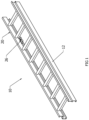
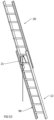
- Figures 35-38 show a simplified extension ladder 10 in the retracted and extended positions.
- the climbing side is seen in figures 35 and 36 and the non-climbing side is in figures 37 and 38 .
- the major components are the power spring unit 86 which is connected to the first base rail 14 by a bracket 84, a pulley on the first base rail 14, a cable anchor 58 on the first fly rail 22, a drum 88 on the power spring unit 86, and the cable 32.
- One end of the cable 32 is fixed to and wraps around the drum 88.
- the cable 32 extends from the drum 88 to the pulley and then to the cable anchor 58 on the first fly rail 22.
- Tension produced in the cable 32 by the power spring unit 86 tends to make the fly section 20 move from the retracted to the extended position.
- Figure 39 and figure 40 show how the cable 32 wraps around the drum 88.
- the fly section 20 is extended as in figure 39 , some amount of cable 32 is taken up by the drum 88.
- the fly section 20 is retracted as in figure 40 , nearly all of the cable 32 has been unwrapped from the drum 88.
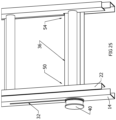
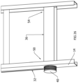
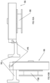
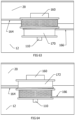
- Figure 41 and figure 42 show an additional feature.
- the power spring unit 86 When the ladder 10 is in use, the power spring unit 86 is in the deployed position of figure 41 , where the power spring unit 86 extend essentially perpendicular from the rungs 18. However, for transporting or storing the ladder 10, the power spring unit 86 can be moved into the stowed position of figure 42 , where the power spring unit 86 is in line and parallel with the rungs 18. (The cable is not shown.) This stowing action is accomplished by the power spring unit 86 pivoting about the end of its bracket 84, as seen in figures 43A and 43B .
- the bracket 84 is able to pivot about a pivot pin 146 between a deployed position where the drum 88 and power spring unit 86 extend perpendicularly from the base section 12 and a stowed position where the drum 88 and power spring unit 86 are parallel with the base section 12 for transporting or stowing the extension ladder 10.
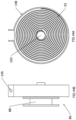
- Figures 44A and 44B show more details of the power spring unit 86 and drum 88.
- a clock-work type power spring 92 attached to the shaft 150produces torque on the shaft 150 which is connected to the drum 88.
- the power spring 92 When the fly section 20 is fully retracted, the power spring 92 is wound most tightly. The power spring 92 unwinds (relaxes) as the fly section 20 moves toward the extended position.
- the power spring 92 is sized to apply torque on the drum 88 and so tension in the cable 32 and so partially offset the weight of the fly section 20 throughout the range of motion of the fly section 20.
- the power spring 92 is disposed in and protected by a housing 148.
- One end of the power spring 92 is attached to the housing 148 and the other end of the power spring 92 is attached to the shaft 150.
- the housing 148 By being attached to the housing 148, it is a fixed point about which the power spring 92 tightens or loosens as the shaft 150 rotates the power spring 92.
- the force applicator 26 is a foot pedal 94 which raises the fly section 20 a distance of one rung spacing each time the pedal is pressed down fully.
- a ratchet stud 156 is attached to the ratchet base 98.
- the ratchet base 98 When the ratchet base 98 is in its lowest position and therefore the foot pedal 94 is in its uppermost at-rest position, the ratchet stud 156 is in contact with the ratchet 152 and so causes it to be in its retracted position. Pushing down on the foot pedal 94 a short distance causes the ratchet base 98 to move upward and away from contact with the ratchet stud 156. This initial movement allows the ratchet 152 to move to its extended position.
- the diameters of the dual diameter drum 162 can be chosen so that an applied gas spring force of 200 pounds on the moveable end of the cable 32 will produce a reaction force on the fly section 20 (through the axle 110) of 20 pounds. Consequently, 1 foot of motion at the moveable end of the cable 32 will cause the fly section 20 to move 10 feet. Thus, a short stroke from a gas spring can produce a long travel of the fly section 20.
- Gas springs are desirable because of their very low spring rate over the length of their stroke. A low spring rate results in a uniform counterbalance force over the full range of the fly section's motion. However, more conventional springs, such as coil springs, could be used if a varying counterbalance force can be tolerated.
- the present disclosure pertains to a method for using an extension ladder 10.
- the method comprises the steps of extending a fly section 20 of the extension ladder 10 relative to a base section 12 of the extension ladder 10. There is the step of leaning the fly section 20 against an object. There is the step of sliding the fly section 20 downwards relative to the base section 12 while a force applicator 26 attached to the fly section 20 and the base section 12 applies a counterbalancing force to the fly section 20 to effectively reduce a weight of the fly section 20.
- the object can be a wall or a pole.
- the present disclosure pertains to a method for manufacturing an extension ladder 10.
- the method comprises the steps of attaching a cable anchor 58 to a first fly rail 22 of a fly section 20 of the extension ladder 10.
- the step of attaching the spring assembly 30 may include the steps of mounting a torque spring 34 around a torque shaft 38, fixing a second end 48 of a torque spring 34 to a torque rung body 42, and fixing a first end 46 of the torque spring 34 to a torque shaft flange 44 which is connected to the torque shaft 38.
- the torque shaft 38 extends and is connected to a torque drum 40.
- the present disclosure pertains to a method for using an extension ladder 10.
- the method comprises the steps of extending a fly section 20 of the extension ladder 10 relative to a base section 12 of the extension ladder 10. There is the step of leaning the fly section 20 against an object 60. There is the step of sliding the fly section 20 downwards relative to the base section 12 while a force applicator 26 attached to the fly section 20 and the base section 12 applies a counterbalancing force from a motor engaged with the force applicator 26 to effectively reduce a weight of the fly section 20.
- Each base rail having an upper end with a cap, and a lower end with a foot
- each fly rail having an upper end with a cap and a lower end with a cap.
- Each foot may be rotably attached to the lower end of each base rail, and may include a tread on the bottom of the foot to better grab the ground and prevent the ladder from sliding when leaning against an object.
- the foot may also include a spur plate extending from the foot to dig into the ground to better fix the ladder in place.
Landscapes
- Engineering & Computer Science (AREA)
- Mechanical Engineering (AREA)
- Ladders (AREA)
Claims (12)
- Verlängerungsleiter (10), umfassend:einen Basisabschnitt (12), der eine erste Basisschiene (14) und eine zweite Basisschiene (16) in einer beabstandeten Beziehung beinhaltet, die eine Vielzahl von Basissprossen (18) beinhaltet, die an der ersten Basisschiene (14) und der zweiten Basisschiene (16) angebracht sind und sich zwischen diesen erstrecken;einen Auszugsabschnitt (20), der eine erste Auszugsschiene (22) und eine zweite Auszugsschiene in einer beabstandeten Beziehung beinhaltet, die eine Vielzahl von Auszugssprossen (18) beinhaltet, die an der ersten Auszugsschiene (22) und der zweiten Auszugsschiene angebracht sind und sich zwischen diesen erstrecken, wobei der Auszugsabschnitt (20) in Gleiteingriff mit dem Basisabschnitt (12) steht; undeine Kraftaufbringeinrichtung (26), die das Gewicht des Auszugsabschnitts (20) teilweise oder zur Gänze ausgleicht, wobei die Kraftaufbringeinrichtung (26) Folgendes umfasst:eine Federanordnung (30), die an der ersten Basisschiene (14) angebracht ist; undein Kabel (32), das sich von der Federanordnung (30) erstreckt und an der ersten Auszugsschiene (22), (20) angebracht ist, dadurch gekennzeichnet, dass die Federanordnung (30) eine Ausgabespule (120), eine Lagerspule (122), die angrenzend an die Ausgabespule (120) angeordnet ist, und eine Antriebsfeder (124) beinhaltet, wobei die Antriebsfeder (124) um die Ausgabespule (120) und die Lagerspule (122) positioniert ist und sich dazwischen erstreckt.
- Verlängerungsleiter (10) nach Anspruch 1, wobei, wenn der Auszugsabschnitt (20) relativ zu dem Basisabschnitt (12) ausgefahren wird, sich das Kabel (32) relativ zu der Federanordnung (30) bewegt und die Federanordnung (30) eine Federkraft durch das Kabel (32) auf die erste Auszugsschiene (22) aufbringt, wobei die Federkraft das Gewicht des Auszugsabschnitts (20) durch das Kabel (32) ausgleicht und wobei mindestens einem Teil eines Gewichts des Auszugsabschnitts (20) durch die Federanordnung (30) über die Federkraft durch das Kabel (32) entgegengewirkt wird, wenn der Auszugsabschnitt (20) relativ zu dem Basisabschnitt (12) zurückgezogen wird.
- Verlängerungsleiter (10) nach Anspruch 2, wobei Bewegung des Kabels (32) die Ausgabespule (120) dreht, während der Auszugsabschnitt (20) ausgefahren und relativ zu dem Basisabschnitt (12) zurückgezogen wird, was veranlasst, dass die Antriebsfeder (124) sich zwischen der Ausgabespule (120) und der Lagerspule (122) bewegt, wobei sich die Antriebsfeder (124) von der Lagerspule (122) zu der Ausgabespule (120) bewegt, während der Auszugsabschnitt (20) relativ zu dem Basisabschnitt (12) ausgefahren wird, und
wobei sich die Antriebsfeder (124) von der Ausgabespule (120) zu der Lagerspule (122) bewegt, während der Auszugsabschnitt (20) relativ zu dem Basisabschnitt (12) zurückgezogen wird. - Verlängerungsleiter (10) nach Anspruch 3, wobei die Antriebsfeder (124) im Wesentlichen auf der Ausgabespule (120) angeordnet ist, wenn der Auszugsabschnitt (20) relativ zu dem Basisabschnitt (12) ausgefahren ist, und
wobei die Antriebsfeder (124) im Wesentlichen auf der Lagerspule (122) angeordnet ist, wenn der Auszugsabschnitt (20) relativ zu dem Basisabschnitt (12) zurückgezogen ist. - Verlängerungsleiter (10) nach Anspruch 1, wobei das Kabel (32) angrenzend an den Boden der ersten Auszugsschiene (22) an einer Innenseite eines Stegs (126) der ersten Auszugsschiene (22) über einen Kabelanker (58) angebracht ist, und
wobei die Federanordnung (30) in der Nähe eines oberen Teils des Basisabschnitts (12) angeordnet und mindestens teilweise von einem Gehäuse (136) umschlossen ist, wobei das Gehäuse (136) an einem Steg (52) der ersten Basisschiene (14) angebracht ist. - Verlängerungsleiter (10) nach Anspruch 1, wobei sich die Ausgabespule (120) und die Lagerspule (122) in entgegengesetzte Richtungen drehen, während der Auszugsabschnitt (20) relativ zu dem Basisabschnitt (12) ausgefahren und zurückgezogen wird.
- Verlängerungsleiter (10) nach Anspruch 1, wobei die Ausgabespule (120) und die Lagerspule (122) weiter einen Trommelteil (132) zum Aufwickeln des Kabels (32) umfassen, während der Auszugsabschnitt (20) relativ zu dem Basisabschnitt (12) ausgefahren und zurückgezogen wird, wobei der Trommelteil (132) an der Ausgabespule (120) und zwischen der Ausgabespule (120) und der ersten Auszugsschiene (22) angebracht ist.
- Verlängerungsleiter (10) nach Anspruch 7, wobei die Bewegung des Kabels (32) den Trommelabschnitt (132) dreht, der wiederum die Ausgabespule (120) dreht, wodurch die Antriebsfeder (124) veranlasst wird, zwischen der Ausgabespule (120) und der Lagerspule (122) zu durchqueren, während der Auszugsabschnitt (20) relativ zu dem Basisabschnitt (12) ausgefahren und zurückgezogen wird.
- Verlängerungsleiter (10) nach Anspruch 7, wobei sich der Trommelteil (132), die Ausgabespule (120) und die Lagerspule (122) von Stangen (134) aus erstrecken, die sich von einem Sockel (144) aus, der an der ersten Basisschiene (14) angebracht ist, erstrecken.
- Verlängerungsleiter (10) nach Anspruch 9, die Federanordnung (30) ferner umfassend eine Rolle (19) neben der Ausgabespule (120) derart, dass sich das Kabel (32) von der Ausgabespule (120) und über die Rolle (19) erstreckt, und wobei sich die Rolle (19) von einer Ecke des Sockels (144) parallel zu den Stangen (134) erstreckt, die sich von dem Sockel (144) aus erstrecken.
- Verlängerungsleiter (10) nach Anspruch 1, ferner Verriegelungen (21) umfassend, um den Auszugsabschnitt (20) an dem Basisabschnitt (12) an verschiedenen Positionen zu halten.
- Verlängerungsleiter (10) nach Anspruch 1, ferner ein Riemenrad (28) umfassend, das an einer der Vielzahl von Auszugssprossen (18) des Basisabschnitts angebracht ist, ein Hubseil (27) und eine Seilklemme (25), die an einer der Vielzahl von Sprossen des Auszugsabschnitts angebracht ist, um das Seil (27) an dem Auszugsabschnitt (20) zu befestigen, wobei das Hubseil (27) durch die Mittelscheibe (28) durchgeht, um den Auszugsabschnitt (20) relativ zu dem Basisabschnitt (12) auszufahren.
Priority Applications (1)
| Application Number | Priority Date | Filing Date | Title |
|---|---|---|---|
| EP25161944.1A EP4541998A3 (de) | 2020-07-22 | 2021-07-19 | Ausziehleiter |
Applications Claiming Priority (3)
| Application Number | Priority Date | Filing Date | Title |
|---|---|---|---|
| US202063055249P | 2020-07-22 | 2020-07-22 | |
| US202163174224P | 2021-04-13 | 2021-04-13 | |
| EP21186536.5A EP3943707B1 (de) | 2020-07-22 | 2021-07-19 | Verlängerungsleiter und verfahren zur herstellung und verwendung einer verlängerungsleiter |
Related Parent Applications (2)
| Application Number | Title | Priority Date | Filing Date |
|---|---|---|---|
| EP21186536.5A Division-Into EP3943707B1 (de) | 2020-07-22 | 2021-07-19 | Verlängerungsleiter und verfahren zur herstellung und verwendung einer verlängerungsleiter |
| EP21186536.5A Division EP3943707B1 (de) | 2020-07-22 | 2021-07-19 | Verlängerungsleiter und verfahren zur herstellung und verwendung einer verlängerungsleiter |
Related Child Applications (2)
| Application Number | Title | Priority Date | Filing Date |
|---|---|---|---|
| EP25161944.1A Division EP4541998A3 (de) | 2020-07-22 | 2021-07-19 | Ausziehleiter |
| EP25161944.1A Division-Into EP4541998A3 (de) | 2020-07-22 | 2021-07-19 | Ausziehleiter |
Publications (3)
| Publication Number | Publication Date |
|---|---|
| EP4234877A2 EP4234877A2 (de) | 2023-08-30 |
| EP4234877A3 EP4234877A3 (de) | 2023-11-08 |
| EP4234877B1 true EP4234877B1 (de) | 2025-04-09 |
Family
ID=76999636
Family Applications (3)
| Application Number | Title | Priority Date | Filing Date |
|---|---|---|---|
| EP23178070.1A Active EP4234877B1 (de) | 2020-07-22 | 2021-07-19 | Verlängerungsleiter |
| EP21186536.5A Active EP3943707B1 (de) | 2020-07-22 | 2021-07-19 | Verlängerungsleiter und verfahren zur herstellung und verwendung einer verlängerungsleiter |
| EP25161944.1A Pending EP4541998A3 (de) | 2020-07-22 | 2021-07-19 | Ausziehleiter |
Family Applications After (2)
| Application Number | Title | Priority Date | Filing Date |
|---|---|---|---|
| EP21186536.5A Active EP3943707B1 (de) | 2020-07-22 | 2021-07-19 | Verlängerungsleiter und verfahren zur herstellung und verwendung einer verlängerungsleiter |
| EP25161944.1A Pending EP4541998A3 (de) | 2020-07-22 | 2021-07-19 | Ausziehleiter |
Country Status (5)
| Country | Link |
|---|---|
| US (1) | US20220025701A1 (de) |
| EP (3) | EP4234877B1 (de) |
| AU (3) | AU2021206781B2 (de) |
| CA (1) | CA3125277A1 (de) |
| MX (1) | MX2021008674A (de) |
Families Citing this family (3)
| Publication number | Priority date | Publication date | Assignee | Title |
|---|---|---|---|---|
| US11834908B2 (en) | 2019-09-12 | 2023-12-05 | Werner Co. | Interlocking ladders and components thereof |
| EP4026981B1 (de) * | 2021-01-08 | 2024-08-07 | Werner Co. | Fernausziehbare leiter und verfahren |
| CN115140251B (zh) * | 2022-06-08 | 2025-06-17 | 安徽省水利水电勘测设计研究总院股份有限公司 | 基于洪涝灾害用的应急救援气垫船及其气垫爬梯 |
Family Cites Families (55)
| Publication number | Priority date | Publication date | Assignee | Title |
|---|---|---|---|---|
| US349370A (en) * | 1886-09-21 | springer | ||
| US139689A (en) * | 1873-06-10 | Improvement in extension-ladders | ||
| US239727A (en) * | 1881-04-05 | Extension-ladder | ||
| US697294A (en) * | 1900-12-21 | 1902-04-08 | Charles B Totman | Extension-ladder. |
| US1767148A (en) * | 1925-04-27 | 1930-06-24 | Berthold V Marschke | Folding and disappearing stairs |
| US1737799A (en) * | 1928-01-21 | 1929-12-03 | Emil C Loetscher | Sliding stairway |
| GB328573A (en) * | 1929-01-29 | 1930-04-29 | Loft Ladders Ltd | Improvements in extension ladders |
| GB428101A (en) * | 1934-01-10 | 1935-05-07 | Reginald Douglas Milles | Improvements in loft ladders |
| GB492303A (en) * | 1937-03-18 | 1938-09-19 | Loft Ladders Ltd | Improvements in loft ladders and the like |
| US2210803A (en) * | 1938-08-25 | 1940-08-06 | Stanley E Dunn | Extension ladder |
| US2198071A (en) * | 1939-02-09 | 1940-04-23 | Artini Vespasiano | Extensible fire ladder |
| US2405505A (en) * | 1945-07-05 | 1946-08-06 | Albert J Kleidon | Ladder hoist |
| US2880829A (en) * | 1956-06-22 | 1959-04-07 | David T Watkins | Anti-climbing shield for towers |
| US3225863A (en) * | 1964-06-04 | 1965-12-28 | Howard T Ludlow | Safety ladder |
| US3386531A (en) * | 1965-10-11 | 1968-06-04 | Werner J. Sallein | Retractable ladder |
| US3871479A (en) * | 1973-07-13 | 1975-03-18 | Clarence H Pelto | Telescoping stairway |
| US3966018A (en) * | 1975-02-12 | 1976-06-29 | Morita Pump Kabushiki Kaisha | Working platform lifting apparatus for aerial ladder truck |
| US4364451A (en) * | 1977-12-16 | 1982-12-21 | Utility Products, Inc. | Ladder lock |
| US4181195A (en) * | 1978-02-13 | 1980-01-01 | Clarke Clifford R | Ladder lock |
| US4396093A (en) * | 1981-01-19 | 1983-08-02 | Zimmerman Mahlon N | Ladder or boom extension system |
| US4640388A (en) * | 1985-02-06 | 1987-02-03 | Walborn John B | Escape device |
| US5101215A (en) * | 1985-05-10 | 1992-03-31 | Chu Associates, Inc. | Telescoping lightweight antenna tower assembly and the like |
| US4605100A (en) * | 1985-08-30 | 1986-08-12 | Uniprode | Ladder extension lock |
| GB8704787D0 (en) * | 1987-02-28 | 1987-04-01 | Maynes D | Step ladder/platform |
| FR2614067A1 (fr) * | 1987-04-14 | 1988-10-21 | Quere Marcel | Echelle auto-elevatrice |
| US5033584A (en) * | 1990-03-02 | 1991-07-23 | Battle Harold P | All-purpose ladder |
| GB2252588B (en) * | 1991-02-05 | 1995-03-08 | Douglas Harvey | Improved method of loft ladder automation |
| US5758745A (en) * | 1996-07-18 | 1998-06-02 | Werner Co. | Extension ladder, combination end cap/guide bracket, and method for climbing |
| DE29713340U1 (de) * | 1997-07-26 | 1998-04-16 | Hymer Leichtmetallbau Gmbh & C | Schiebeleiter mit Seilzug und Sperreinrichtung |
| KR19990017256A (ko) * | 1997-08-22 | 1999-03-15 | 황성규 | 신축형 사다리 |
| US6131702A (en) * | 1998-05-29 | 2000-10-17 | Berridge; Harold Arthur | Home platform lift for attached garages |
| CN2570435Y (zh) * | 2002-09-11 | 2003-09-03 | 李�杰 | 防脱滑的延伸式梯子 |
| DE10257108B4 (de) * | 2002-12-05 | 2008-05-21 | Eisenmann Anlagenbau Gmbh & Co. Kg | Fahrbare Hubvorrichtung |
| US7416055B2 (en) * | 2003-09-08 | 2008-08-26 | Spacelift Products, Inc. | Platform lift apparatus for attic storage space |
| US8028804B2 (en) * | 2006-02-06 | 2011-10-04 | Jean-Pierre Lair | Automatic ladder for attic access |
| US20070181370A1 (en) * | 2006-02-06 | 2007-08-09 | Stephen Kemp-Banks | Stabilized ladder |
| KR100725267B1 (ko) * | 2006-04-19 | 2007-06-04 | (주)관동건업 | 비상탈출용 사다리 장치 |
| EP2182164B1 (de) * | 2008-10-28 | 2012-07-25 | Iveco Magirus Ag | Leiterset für Hebe-Rettungsfahrzeuge |
| US9080383B2 (en) * | 2009-03-02 | 2015-07-14 | D B Industries, Llc | Climb assist system |
| KR100949777B1 (ko) * | 2009-07-14 | 2010-03-30 | 송일상 | 높이조절 사다리의 승강장치 |
| US9169693B2 (en) * | 2009-09-18 | 2015-10-27 | Safe Rack Llc | Mobile access unit and cage |
| PL224400B1 (pl) * | 2010-01-18 | 2016-12-30 | Fakro Pp Spółka Z Ograniczoną Odpowiedzialnością | Składane schody drabiniaste, zwłaszcza metalowe |
| US8875839B1 (en) * | 2012-06-28 | 2014-11-04 | William Licea | Fall restraint system for telescoping ladders |
| US20140097042A1 (en) * | 2012-10-05 | 2014-04-10 | Brian Wright | Motorized Extension Ladder |
| US10605003B2 (en) * | 2015-02-20 | 2020-03-31 | Philip F. Lanzafame | Ladder extension brake |
| US9598875B1 (en) * | 2016-01-28 | 2017-03-21 | Multiquip, Inc. | Telescoping mast assembly with safety latch system |
| FI127507B (en) * | 2016-04-06 | 2018-08-15 | Ixolift Oy | Personnel lift |
| KR101767014B1 (ko) * | 2016-11-02 | 2017-08-09 | 서동영 | 전동 드라이버로 길이 조절이 가능한 자동 사다리 |
| KR20180101734A (ko) * | 2017-03-06 | 2018-09-14 | 주식회사 엔케이 | 2단 사다리 |
| US20190186151A1 (en) * | 2017-12-14 | 2019-06-20 | Bernabe Canlas | Attic Ladder and Kit |
| CN109267927B (zh) * | 2018-09-13 | 2020-10-13 | 滁州金诚金属制品有限公司 | 一种便于调节的脚踩式升降梯 |
| CN109667397A (zh) * | 2019-02-14 | 2019-04-23 | 陈丽珍 | 一种半固定式伸缩楼梯 |
| CN110104205A (zh) * | 2019-05-28 | 2019-08-09 | 广州市江弘航空器材有限公司 | 一种航空工作梯 |
| CN210622687U (zh) * | 2019-07-19 | 2020-05-26 | 周红良 | 多功能运输梯 |
| US12023526B2 (en) * | 2020-01-23 | 2024-07-02 | Pella Corporation | Escape systems for descending a person from a window |
-
2021
- 2021-07-19 EP EP23178070.1A patent/EP4234877B1/de active Active
- 2021-07-19 US US17/379,714 patent/US20220025701A1/en active Pending
- 2021-07-19 EP EP21186536.5A patent/EP3943707B1/de active Active
- 2021-07-19 AU AU2021206781A patent/AU2021206781B2/en active Active
- 2021-07-19 EP EP25161944.1A patent/EP4541998A3/de active Pending
- 2021-07-19 MX MX2021008674A patent/MX2021008674A/es unknown
- 2021-07-20 CA CA3125277A patent/CA3125277A1/en active Pending
-
2023
- 2023-05-05 AU AU2023202810A patent/AU2023202810B2/en active Active
-
2025
- 2025-04-23 AU AU2025202840A patent/AU2025202840A1/en active Pending
Also Published As
| Publication number | Publication date |
|---|---|
| CA3125277A1 (en) | 2022-01-22 |
| EP3943707B1 (de) | 2023-11-01 |
| AU2021206781B2 (en) | 2023-05-18 |
| US20220025701A1 (en) | 2022-01-27 |
| EP4234877A2 (de) | 2023-08-30 |
| EP4234877A3 (de) | 2023-11-08 |
| EP3943707A1 (de) | 2022-01-26 |
| EP4541998A3 (de) | 2025-05-21 |
| AU2023202810B2 (en) | 2025-02-27 |
| AU2021206781A1 (en) | 2022-02-10 |
| EP4541998A2 (de) | 2025-04-23 |
| MX2021008674A (es) | 2022-01-24 |
| AU2025202840A1 (en) | 2025-05-08 |
| AU2023202810A1 (en) | 2023-05-25 |
Similar Documents
| Publication | Publication Date | Title |
|---|---|---|
| AU2023202810B2 (en) | Extension Ladder and Methods of Making and Using an Extension Ladder | |
| US10145171B2 (en) | Control for movable rail | |
| US6318661B1 (en) | Spring motor | |
| US7287570B2 (en) | Window covering lifting system and method | |
| US20070051477A1 (en) | Worm gear drive mechanism for a covering for architectural openings | |
| US20170081912A1 (en) | Systems and methods for multiple operational blind partitions | |
| US20160290043A1 (en) | Window shade with spring assist | |
| JP3261106B2 (ja) | 横型ブラインドのスラット角度調節装置 | |
| CN113309459A (zh) | 一种电力施工用的维修挂梯 | |
| JP3542739B2 (ja) | 遮蔽材の昇降装置 | |
| CA1243278A (en) | Portable and collapsible derrick structure | |
| JP3288641B2 (ja) | ブラインドの昇降装置 | |
| CN215565658U (zh) | 一种电力施工用的维修挂梯 | |
| CN214302975U (zh) | 一种建筑施工用防坠支架 | |
| CN220667417U (zh) | 自动升降卷帘 | |
| CN216863542U (zh) | 一种升降货梯 | |
| CN209099750U (zh) | 一种多功能电梯井作业平台 | |
| JPH031990Y2 (de) | ||
| CN223646021U (zh) | 一种便携式放线器 | |
| CN217350181U (zh) | 一种电缆自动盘线装置 | |
| JPH08170477A (ja) | カーテン開閉装置 | |
| CN222374003U (zh) | 一种电力辅助架线装置 | |
| CN216918183U (zh) | 一种用于自动上线喷涂机器人的卷线机构 | |
| CN221027197U (zh) | 一种装配式建筑构件吊装引导装置 | |
| JP2533333Y2 (ja) | 伸縮避難はしごにおける緩降巻上げ装置 |
Legal Events
| Date | Code | Title | Description |
|---|---|---|---|
| PUAI | Public reference made under article 153(3) epc to a published international application that has entered the european phase |
Free format text: ORIGINAL CODE: 0009012 |
|
| STAA | Information on the status of an ep patent application or granted ep patent |
Free format text: STATUS: THE APPLICATION HAS BEEN PUBLISHED |
|
| AC | Divisional application: reference to earlier application |
Ref document number: 3943707 Country of ref document: EP Kind code of ref document: P |
|
| AK | Designated contracting states |
Kind code of ref document: A2 Designated state(s): AL AT BE BG CH CY CZ DE DK EE ES FI FR GB GR HR HU IE IS IT LI LT LU LV MC MK MT NL NO PL PT RO RS SE SI SK SM TR |
|
| REG | Reference to a national code |
Ref country code: DE Ref legal event code: R079 Free format text: PREVIOUS MAIN CLASS: E06C0007040000 Ipc: E06C0001120000 Ref country code: DE Ref legal event code: R079 Ref document number: 602021029091 Country of ref document: DE Free format text: PREVIOUS MAIN CLASS: E06C0007040000 Ipc: E06C0001120000 |
|
| PUAL | Search report despatched |
Free format text: ORIGINAL CODE: 0009013 |
|
| AK | Designated contracting states |
Kind code of ref document: A3 Designated state(s): AL AT BE BG CH CY CZ DE DK EE ES FI FR GB GR HR HU IE IS IT LI LT LU LV MC MK MT NL NO PL PT RO RS SE SI SK SM TR |
|
| RIC1 | Information provided on ipc code assigned before grant |
Ipc: E06C 7/04 20060101ALI20230929BHEP Ipc: E06C 7/02 20060101ALI20230929BHEP Ipc: E06C 1/12 20060101AFI20230929BHEP |
|
| STAA | Information on the status of an ep patent application or granted ep patent |
Free format text: STATUS: REQUEST FOR EXAMINATION WAS MADE |
|
| 17P | Request for examination filed |
Effective date: 20240507 |
|
| RBV | Designated contracting states (corrected) |
Designated state(s): AL AT BE BG CH CY CZ DE DK EE ES FI FR GB GR HR HU IE IS IT LI LT LU LV MC MK MT NL NO PL PT RO RS SE SI SK SM TR |
|
| RIN1 | Information on inventor provided before grant (corrected) |
Inventor name: POZGAY, DAVID Inventor name: HUGHES, DEVIN Inventor name: DACIC, SLAVISA Inventor name: LAURICELLA, JERRY Inventor name: LENTINE, TEK Inventor name: SCHEURICH, MICHAEL |
|
| STAA | Information on the status of an ep patent application or granted ep patent |
Free format text: STATUS: EXAMINATION IS IN PROGRESS |
|
| 17Q | First examination report despatched |
Effective date: 20240708 |
|
| GRAP | Despatch of communication of intention to grant a patent |
Free format text: ORIGINAL CODE: EPIDOSNIGR1 |
|
| STAA | Information on the status of an ep patent application or granted ep patent |
Free format text: STATUS: GRANT OF PATENT IS INTENDED |
|
| INTG | Intention to grant announced |
Effective date: 20241106 |
|
| GRAS | Grant fee paid |
Free format text: ORIGINAL CODE: EPIDOSNIGR3 |
|
| GRAA | (expected) grant |
Free format text: ORIGINAL CODE: 0009210 |
|
| STAA | Information on the status of an ep patent application or granted ep patent |
Free format text: STATUS: THE PATENT HAS BEEN GRANTED |
|
| AC | Divisional application: reference to earlier application |
Ref document number: 3943707 Country of ref document: EP Kind code of ref document: P |
|
| AK | Designated contracting states |
Kind code of ref document: B1 Designated state(s): AL AT BE BG CH CY CZ DE DK EE ES FI FR GB GR HR HU IE IS IT LI LT LU LV MC MK MT NL NO PL PT RO RS SE SI SK SM TR |
|
| REG | Reference to a national code |
Ref country code: GB Ref legal event code: FG4D |
|
| REG | Reference to a national code |
Ref country code: CH Ref legal event code: EP |
|
| REG | Reference to a national code |
Ref country code: DE Ref legal event code: R096 Ref document number: 602021029091 Country of ref document: DE |
|
| REG | Reference to a national code |
Ref country code: IE Ref legal event code: FG4D |
|
| PGFP | Annual fee paid to national office [announced via postgrant information from national office to epo] |
Ref country code: GB Payment date: 20250529 Year of fee payment: 5 |
|
| PGFP | Annual fee paid to national office [announced via postgrant information from national office to epo] |
Ref country code: FR Payment date: 20250610 Year of fee payment: 5 |
|
| REG | Reference to a national code |
Ref country code: NL Ref legal event code: MP Effective date: 20250409 |
|
| PG25 | Lapsed in a contracting state [announced via postgrant information from national office to epo] |
Ref country code: NL Free format text: LAPSE BECAUSE OF FAILURE TO SUBMIT A TRANSLATION OF THE DESCRIPTION OR TO PAY THE FEE WITHIN THE PRESCRIBED TIME-LIMIT Effective date: 20250409 |
|
| REG | Reference to a national code |
Ref country code: AT Ref legal event code: MK05 Ref document number: 1783656 Country of ref document: AT Kind code of ref document: T Effective date: 20250409 |
|
| PG25 | Lapsed in a contracting state [announced via postgrant information from national office to epo] |
Ref country code: FI Free format text: LAPSE BECAUSE OF FAILURE TO SUBMIT A TRANSLATION OF THE DESCRIPTION OR TO PAY THE FEE WITHIN THE PRESCRIBED TIME-LIMIT Effective date: 20250409 Ref country code: ES Free format text: LAPSE BECAUSE OF FAILURE TO SUBMIT A TRANSLATION OF THE DESCRIPTION OR TO PAY THE FEE WITHIN THE PRESCRIBED TIME-LIMIT Effective date: 20250409 Ref country code: PT Free format text: LAPSE BECAUSE OF FAILURE TO SUBMIT A TRANSLATION OF THE DESCRIPTION OR TO PAY THE FEE WITHIN THE PRESCRIBED TIME-LIMIT Effective date: 20250811 |
|
| PGFP | Annual fee paid to national office [announced via postgrant information from national office to epo] |
Ref country code: DE Payment date: 20250604 Year of fee payment: 5 |
|
| REG | Reference to a national code |
Ref country code: LT Ref legal event code: MG9D |
|
| PG25 | Lapsed in a contracting state [announced via postgrant information from national office to epo] |
Ref country code: GR Free format text: LAPSE BECAUSE OF FAILURE TO SUBMIT A TRANSLATION OF THE DESCRIPTION OR TO PAY THE FEE WITHIN THE PRESCRIBED TIME-LIMIT Effective date: 20250710 Ref country code: NO Free format text: LAPSE BECAUSE OF FAILURE TO SUBMIT A TRANSLATION OF THE DESCRIPTION OR TO PAY THE FEE WITHIN THE PRESCRIBED TIME-LIMIT Effective date: 20250709 |
|
| PG25 | Lapsed in a contracting state [announced via postgrant information from national office to epo] |
Ref country code: PL Free format text: LAPSE BECAUSE OF FAILURE TO SUBMIT A TRANSLATION OF THE DESCRIPTION OR TO PAY THE FEE WITHIN THE PRESCRIBED TIME-LIMIT Effective date: 20250409 |
|
| PG25 | Lapsed in a contracting state [announced via postgrant information from national office to epo] |
Ref country code: BG Free format text: LAPSE BECAUSE OF FAILURE TO SUBMIT A TRANSLATION OF THE DESCRIPTION OR TO PAY THE FEE WITHIN THE PRESCRIBED TIME-LIMIT Effective date: 20250409 |
|
| PG25 | Lapsed in a contracting state [announced via postgrant information from national office to epo] |
Ref country code: HR Free format text: LAPSE BECAUSE OF FAILURE TO SUBMIT A TRANSLATION OF THE DESCRIPTION OR TO PAY THE FEE WITHIN THE PRESCRIBED TIME-LIMIT Effective date: 20250409 |
|
| PG25 | Lapsed in a contracting state [announced via postgrant information from national office to epo] |
Ref country code: AT Free format text: LAPSE BECAUSE OF FAILURE TO SUBMIT A TRANSLATION OF THE DESCRIPTION OR TO PAY THE FEE WITHIN THE PRESCRIBED TIME-LIMIT Effective date: 20250409 |
|
| PG25 | Lapsed in a contracting state [announced via postgrant information from national office to epo] |
Ref country code: RS Free format text: LAPSE BECAUSE OF FAILURE TO SUBMIT A TRANSLATION OF THE DESCRIPTION OR TO PAY THE FEE WITHIN THE PRESCRIBED TIME-LIMIT Effective date: 20250709 |
|
| PG25 | Lapsed in a contracting state [announced via postgrant information from national office to epo] |
Ref country code: IS Free format text: LAPSE BECAUSE OF FAILURE TO SUBMIT A TRANSLATION OF THE DESCRIPTION OR TO PAY THE FEE WITHIN THE PRESCRIBED TIME-LIMIT Effective date: 20250809 |
|
| PG25 | Lapsed in a contracting state [announced via postgrant information from national office to epo] |
Ref country code: LV Free format text: LAPSE BECAUSE OF FAILURE TO SUBMIT A TRANSLATION OF THE DESCRIPTION OR TO PAY THE FEE WITHIN THE PRESCRIBED TIME-LIMIT Effective date: 20250409 |
|
| PG25 | Lapsed in a contracting state [announced via postgrant information from national office to epo] |
Ref country code: SM Free format text: LAPSE BECAUSE OF FAILURE TO SUBMIT A TRANSLATION OF THE DESCRIPTION OR TO PAY THE FEE WITHIN THE PRESCRIBED TIME-LIMIT Effective date: 20250409 Ref country code: DK Free format text: LAPSE BECAUSE OF FAILURE TO SUBMIT A TRANSLATION OF THE DESCRIPTION OR TO PAY THE FEE WITHIN THE PRESCRIBED TIME-LIMIT Effective date: 20250409 |
|
| PG25 | Lapsed in a contracting state [announced via postgrant information from national office to epo] |
Ref country code: CZ Free format text: LAPSE BECAUSE OF FAILURE TO SUBMIT A TRANSLATION OF THE DESCRIPTION OR TO PAY THE FEE WITHIN THE PRESCRIBED TIME-LIMIT Effective date: 20250409 |
|
| PG25 | Lapsed in a contracting state [announced via postgrant information from national office to epo] |
Ref country code: EE Free format text: LAPSE BECAUSE OF FAILURE TO SUBMIT A TRANSLATION OF THE DESCRIPTION OR TO PAY THE FEE WITHIN THE PRESCRIBED TIME-LIMIT Effective date: 20250409 |
|
| PG25 | Lapsed in a contracting state [announced via postgrant information from national office to epo] |
Ref country code: SK Free format text: LAPSE BECAUSE OF FAILURE TO SUBMIT A TRANSLATION OF THE DESCRIPTION OR TO PAY THE FEE WITHIN THE PRESCRIBED TIME-LIMIT Effective date: 20250409 |
|
| PG25 | Lapsed in a contracting state [announced via postgrant information from national office to epo] |
Ref country code: IT Free format text: LAPSE BECAUSE OF FAILURE TO SUBMIT A TRANSLATION OF THE DESCRIPTION OR TO PAY THE FEE WITHIN THE PRESCRIBED TIME-LIMIT Effective date: 20250409 |
|
| PLBE | No opposition filed within time limit |
Free format text: ORIGINAL CODE: 0009261 |
|
| STAA | Information on the status of an ep patent application or granted ep patent |
Free format text: STATUS: NO OPPOSITION FILED WITHIN TIME LIMIT |