EP4234205A2 - Dispositif d'extrusion et procédé pour influencer l'épaisseur de paroi d'un profilé en plastique extrudé - Google Patents
Dispositif d'extrusion et procédé pour influencer l'épaisseur de paroi d'un profilé en plastique extrudé Download PDFInfo
- Publication number
- EP4234205A2 EP4234205A2 EP23177320.1A EP23177320A EP4234205A2 EP 4234205 A2 EP4234205 A2 EP 4234205A2 EP 23177320 A EP23177320 A EP 23177320A EP 4234205 A2 EP4234205 A2 EP 4234205A2
- Authority
- EP
- European Patent Office
- Prior art keywords
- extrusion
- temperature
- temperature control
- plastic
- wall
- Prior art date
- Legal status (The legal status is an assumption and is not a legal conclusion. Google has not performed a legal analysis and makes no representation as to the accuracy of the status listed.)
- Pending
Links
- 238000001125 extrusion Methods 0.000 title claims abstract description 205
- 238000000034 method Methods 0.000 title claims abstract description 24
- 239000003000 extruded plastic Substances 0.000 title description 10
- 239000004033 plastic Substances 0.000 claims abstract description 138
- 229920003023 plastic Polymers 0.000 claims abstract description 138
- 230000008569 process Effects 0.000 claims abstract description 15
- 238000005496 tempering Methods 0.000 claims description 44
- 230000008859 change Effects 0.000 claims description 28
- 230000033228 biological regulation Effects 0.000 claims description 12
- 238000011144 upstream manufacturing Methods 0.000 claims description 12
- 230000001105 regulatory effect Effects 0.000 claims description 11
- 230000001276 controlling effect Effects 0.000 claims description 5
- 230000008878 coupling Effects 0.000 claims description 3
- 238000010168 coupling process Methods 0.000 claims description 3
- 238000005859 coupling reaction Methods 0.000 claims description 3
- 239000011810 insulating material Substances 0.000 claims description 3
- 230000007704 transition Effects 0.000 claims description 3
- 238000001816 cooling Methods 0.000 description 24
- 238000010438 heat treatment Methods 0.000 description 22
- 230000000694 effects Effects 0.000 description 21
- 239000000155 melt Substances 0.000 description 17
- 239000007789 gas Substances 0.000 description 16
- 239000012530 fluid Substances 0.000 description 15
- 239000007788 liquid Substances 0.000 description 15
- 238000005259 measurement Methods 0.000 description 13
- 239000000463 material Substances 0.000 description 8
- 230000002093 peripheral effect Effects 0.000 description 8
- 238000009413 insulation Methods 0.000 description 7
- 238000004519 manufacturing process Methods 0.000 description 7
- 230000009467 reduction Effects 0.000 description 6
- 238000012546 transfer Methods 0.000 description 4
- 229910000831 Steel Inorganic materials 0.000 description 3
- 238000013461 design Methods 0.000 description 3
- 239000010410 layer Substances 0.000 description 3
- 230000004044 response Effects 0.000 description 3
- 238000007493 shaping process Methods 0.000 description 3
- 239000010959 steel Substances 0.000 description 3
- 230000008719 thickening Effects 0.000 description 3
- RYGMFSIKBFXOCR-UHFFFAOYSA-N Copper Chemical compound [Cu] RYGMFSIKBFXOCR-UHFFFAOYSA-N 0.000 description 2
- 230000008901 benefit Effects 0.000 description 2
- 229910052802 copper Inorganic materials 0.000 description 2
- 239000010949 copper Substances 0.000 description 2
- 230000007423 decrease Effects 0.000 description 2
- 230000003247 decreasing effect Effects 0.000 description 2
- 238000006073 displacement reaction Methods 0.000 description 2
- 230000006698 induction Effects 0.000 description 2
- 239000012212 insulator Substances 0.000 description 2
- 230000003993 interaction Effects 0.000 description 2
- 238000000691 measurement method Methods 0.000 description 2
- 239000002184 metal Substances 0.000 description 2
- 229910052751 metal Inorganic materials 0.000 description 2
- 238000007789 sealing Methods 0.000 description 2
- 206010013710 Drug interaction Diseases 0.000 description 1
- 240000003517 Elaeocarpus dentatus Species 0.000 description 1
- 230000005679 Peltier effect Effects 0.000 description 1
- 230000009471 action Effects 0.000 description 1
- 230000004913 activation Effects 0.000 description 1
- 238000013459 approach Methods 0.000 description 1
- 230000015572 biosynthetic process Effects 0.000 description 1
- 238000006243 chemical reaction Methods 0.000 description 1
- 239000007795 chemical reaction product Substances 0.000 description 1
- 238000011109 contamination Methods 0.000 description 1
- 239000002826 coolant Substances 0.000 description 1
- 238000005520 cutting process Methods 0.000 description 1
- 230000001419 dependent effect Effects 0.000 description 1
- 238000001514 detection method Methods 0.000 description 1
- 238000009826 distribution Methods 0.000 description 1
- 230000003628 erosive effect Effects 0.000 description 1
- 238000002474 experimental method Methods 0.000 description 1
- 238000011049 filling Methods 0.000 description 1
- 238000009472 formulation Methods 0.000 description 1
- 230000017525 heat dissipation Effects 0.000 description 1
- 239000012535 impurity Substances 0.000 description 1
- 238000009434 installation Methods 0.000 description 1
- 238000002955 isolation Methods 0.000 description 1
- 238000011068 loading method Methods 0.000 description 1
- 239000000314 lubricant Substances 0.000 description 1
- 238000011326 mechanical measurement Methods 0.000 description 1
- 238000003801 milling Methods 0.000 description 1
- 238000002156 mixing Methods 0.000 description 1
- 239000000203 mixture Substances 0.000 description 1
- 239000003921 oil Substances 0.000 description 1
- 230000003287 optical effect Effects 0.000 description 1
- 239000002245 particle Substances 0.000 description 1
- 230000000149 penetrating effect Effects 0.000 description 1
- 238000003825 pressing Methods 0.000 description 1
- 239000000047 product Substances 0.000 description 1
- 239000000523 sample Substances 0.000 description 1
- 239000012791 sliding layer Substances 0.000 description 1
- 238000007669 thermal treatment Methods 0.000 description 1
- 230000001960 triggered effect Effects 0.000 description 1
- XLYOFNOQVPJJNP-UHFFFAOYSA-N water Substances O XLYOFNOQVPJJNP-UHFFFAOYSA-N 0.000 description 1
Images


Classifications
-
- B—PERFORMING OPERATIONS; TRANSPORTING
- B29—WORKING OF PLASTICS; WORKING OF SUBSTANCES IN A PLASTIC STATE IN GENERAL
- B29C—SHAPING OR JOINING OF PLASTICS; SHAPING OF MATERIAL IN A PLASTIC STATE, NOT OTHERWISE PROVIDED FOR; AFTER-TREATMENT OF THE SHAPED PRODUCTS, e.g. REPAIRING
- B29C48/00—Extrusion moulding, i.e. expressing the moulding material through a die or nozzle which imparts the desired form; Apparatus therefor
- B29C48/25—Component parts, details or accessories; Auxiliary operations
- B29C48/30—Extrusion nozzles or dies
- B29C48/32—Extrusion nozzles or dies with annular openings, e.g. for forming tubular articles
- B29C48/335—Multiple annular extrusion nozzles in coaxial arrangement, e.g. for making multi-layered tubular articles
- B29C48/336—Multiple annular extrusion nozzles in coaxial arrangement, e.g. for making multi-layered tubular articles the components merging one by one down streams in the die
- B29C48/3363—Multiple annular extrusion nozzles in coaxial arrangement, e.g. for making multi-layered tubular articles the components merging one by one down streams in the die using a layered die, e.g. stacked discs
-
- B—PERFORMING OPERATIONS; TRANSPORTING
- B29—WORKING OF PLASTICS; WORKING OF SUBSTANCES IN A PLASTIC STATE IN GENERAL
- B29C—SHAPING OR JOINING OF PLASTICS; SHAPING OF MATERIAL IN A PLASTIC STATE, NOT OTHERWISE PROVIDED FOR; AFTER-TREATMENT OF THE SHAPED PRODUCTS, e.g. REPAIRING
- B29C48/00—Extrusion moulding, i.e. expressing the moulding material through a die or nozzle which imparts the desired form; Apparatus therefor
- B29C48/25—Component parts, details or accessories; Auxiliary operations
- B29C48/92—Measuring, controlling or regulating
-
- B—PERFORMING OPERATIONS; TRANSPORTING
- B29—WORKING OF PLASTICS; WORKING OF SUBSTANCES IN A PLASTIC STATE IN GENERAL
- B29C—SHAPING OR JOINING OF PLASTICS; SHAPING OF MATERIAL IN A PLASTIC STATE, NOT OTHERWISE PROVIDED FOR; AFTER-TREATMENT OF THE SHAPED PRODUCTS, e.g. REPAIRING
- B29C48/00—Extrusion moulding, i.e. expressing the moulding material through a die or nozzle which imparts the desired form; Apparatus therefor
- B29C48/03—Extrusion moulding, i.e. expressing the moulding material through a die or nozzle which imparts the desired form; Apparatus therefor characterised by the shape of the extruded material at extrusion
- B29C48/09—Articles with cross-sections having partially or fully enclosed cavities, e.g. pipes or channels
- B29C48/11—Articles with cross-sections having partially or fully enclosed cavities, e.g. pipes or channels comprising two or more partially or fully enclosed cavities, e.g. honeycomb-shaped
-
- B—PERFORMING OPERATIONS; TRANSPORTING
- B29—WORKING OF PLASTICS; WORKING OF SUBSTANCES IN A PLASTIC STATE IN GENERAL
- B29C—SHAPING OR JOINING OF PLASTICS; SHAPING OF MATERIAL IN A PLASTIC STATE, NOT OTHERWISE PROVIDED FOR; AFTER-TREATMENT OF THE SHAPED PRODUCTS, e.g. REPAIRING
- B29C48/00—Extrusion moulding, i.e. expressing the moulding material through a die or nozzle which imparts the desired form; Apparatus therefor
- B29C48/03—Extrusion moulding, i.e. expressing the moulding material through a die or nozzle which imparts the desired form; Apparatus therefor characterised by the shape of the extruded material at extrusion
- B29C48/12—Articles with an irregular circumference when viewed in cross-section, e.g. window profiles
-
- B—PERFORMING OPERATIONS; TRANSPORTING
- B29—WORKING OF PLASTICS; WORKING OF SUBSTANCES IN A PLASTIC STATE IN GENERAL
- B29C—SHAPING OR JOINING OF PLASTICS; SHAPING OF MATERIAL IN A PLASTIC STATE, NOT OTHERWISE PROVIDED FOR; AFTER-TREATMENT OF THE SHAPED PRODUCTS, e.g. REPAIRING
- B29C48/00—Extrusion moulding, i.e. expressing the moulding material through a die or nozzle which imparts the desired form; Apparatus therefor
- B29C48/15—Extrusion moulding, i.e. expressing the moulding material through a die or nozzle which imparts the desired form; Apparatus therefor incorporating preformed parts or layers, e.g. extrusion moulding around inserts
- B29C48/151—Coating hollow articles
-
- B—PERFORMING OPERATIONS; TRANSPORTING
- B29—WORKING OF PLASTICS; WORKING OF SUBSTANCES IN A PLASTIC STATE IN GENERAL
- B29C—SHAPING OR JOINING OF PLASTICS; SHAPING OF MATERIAL IN A PLASTIC STATE, NOT OTHERWISE PROVIDED FOR; AFTER-TREATMENT OF THE SHAPED PRODUCTS, e.g. REPAIRING
- B29C48/00—Extrusion moulding, i.e. expressing the moulding material through a die or nozzle which imparts the desired form; Apparatus therefor
- B29C48/25—Component parts, details or accessories; Auxiliary operations
- B29C48/30—Extrusion nozzles or dies
- B29C48/3001—Extrusion nozzles or dies characterised by the material or their manufacturing process
-
- B—PERFORMING OPERATIONS; TRANSPORTING
- B29—WORKING OF PLASTICS; WORKING OF SUBSTANCES IN A PLASTIC STATE IN GENERAL
- B29C—SHAPING OR JOINING OF PLASTICS; SHAPING OF MATERIAL IN A PLASTIC STATE, NOT OTHERWISE PROVIDED FOR; AFTER-TREATMENT OF THE SHAPED PRODUCTS, e.g. REPAIRING
- B29C48/00—Extrusion moulding, i.e. expressing the moulding material through a die or nozzle which imparts the desired form; Apparatus therefor
- B29C48/25—Component parts, details or accessories; Auxiliary operations
- B29C48/78—Thermal treatment of the extrusion moulding material or of preformed parts or layers, e.g. by heating or cooling
- B29C48/86—Thermal treatment of the extrusion moulding material or of preformed parts or layers, e.g. by heating or cooling at the nozzle zone
- B29C48/865—Heating
-
- B—PERFORMING OPERATIONS; TRANSPORTING
- B29—WORKING OF PLASTICS; WORKING OF SUBSTANCES IN A PLASTIC STATE IN GENERAL
- B29C—SHAPING OR JOINING OF PLASTICS; SHAPING OF MATERIAL IN A PLASTIC STATE, NOT OTHERWISE PROVIDED FOR; AFTER-TREATMENT OF THE SHAPED PRODUCTS, e.g. REPAIRING
- B29C48/00—Extrusion moulding, i.e. expressing the moulding material through a die or nozzle which imparts the desired form; Apparatus therefor
- B29C48/25—Component parts, details or accessories; Auxiliary operations
- B29C48/78—Thermal treatment of the extrusion moulding material or of preformed parts or layers, e.g. by heating or cooling
- B29C48/86—Thermal treatment of the extrusion moulding material or of preformed parts or layers, e.g. by heating or cooling at the nozzle zone
- B29C48/87—Cooling
-
- B—PERFORMING OPERATIONS; TRANSPORTING
- B29—WORKING OF PLASTICS; WORKING OF SUBSTANCES IN A PLASTIC STATE IN GENERAL
- B29C—SHAPING OR JOINING OF PLASTICS; SHAPING OF MATERIAL IN A PLASTIC STATE, NOT OTHERWISE PROVIDED FOR; AFTER-TREATMENT OF THE SHAPED PRODUCTS, e.g. REPAIRING
- B29C48/00—Extrusion moulding, i.e. expressing the moulding material through a die or nozzle which imparts the desired form; Apparatus therefor
- B29C48/25—Component parts, details or accessories; Auxiliary operations
- B29C48/78—Thermal treatment of the extrusion moulding material or of preformed parts or layers, e.g. by heating or cooling
- B29C48/86—Thermal treatment of the extrusion moulding material or of preformed parts or layers, e.g. by heating or cooling at the nozzle zone
- B29C48/872—Thermal treatment of the extrusion moulding material or of preformed parts or layers, e.g. by heating or cooling at the nozzle zone characterised by differential heating or cooling
-
- B—PERFORMING OPERATIONS; TRANSPORTING
- B29—WORKING OF PLASTICS; WORKING OF SUBSTANCES IN A PLASTIC STATE IN GENERAL
- B29C—SHAPING OR JOINING OF PLASTICS; SHAPING OF MATERIAL IN A PLASTIC STATE, NOT OTHERWISE PROVIDED FOR; AFTER-TREATMENT OF THE SHAPED PRODUCTS, e.g. REPAIRING
- B29C2948/00—Indexing scheme relating to extrusion moulding
- B29C2948/92—Measuring, controlling or regulating
- B29C2948/92009—Measured parameter
- B29C2948/92114—Dimensions
- B29C2948/92152—Thickness
-
- B—PERFORMING OPERATIONS; TRANSPORTING
- B29—WORKING OF PLASTICS; WORKING OF SUBSTANCES IN A PLASTIC STATE IN GENERAL
- B29C—SHAPING OR JOINING OF PLASTICS; SHAPING OF MATERIAL IN A PLASTIC STATE, NOT OTHERWISE PROVIDED FOR; AFTER-TREATMENT OF THE SHAPED PRODUCTS, e.g. REPAIRING
- B29C2948/00—Indexing scheme relating to extrusion moulding
- B29C2948/92—Measuring, controlling or regulating
- B29C2948/92504—Controlled parameter
- B29C2948/9258—Velocity
- B29C2948/926—Flow or feed rate
-
- B—PERFORMING OPERATIONS; TRANSPORTING
- B29—WORKING OF PLASTICS; WORKING OF SUBSTANCES IN A PLASTIC STATE IN GENERAL
- B29C—SHAPING OR JOINING OF PLASTICS; SHAPING OF MATERIAL IN A PLASTIC STATE, NOT OTHERWISE PROVIDED FOR; AFTER-TREATMENT OF THE SHAPED PRODUCTS, e.g. REPAIRING
- B29C2948/00—Indexing scheme relating to extrusion moulding
- B29C2948/92—Measuring, controlling or regulating
- B29C2948/92504—Controlled parameter
- B29C2948/92609—Dimensions
- B29C2948/92647—Thickness
-
- B—PERFORMING OPERATIONS; TRANSPORTING
- B29—WORKING OF PLASTICS; WORKING OF SUBSTANCES IN A PLASTIC STATE IN GENERAL
- B29C—SHAPING OR JOINING OF PLASTICS; SHAPING OF MATERIAL IN A PLASTIC STATE, NOT OTHERWISE PROVIDED FOR; AFTER-TREATMENT OF THE SHAPED PRODUCTS, e.g. REPAIRING
- B29C2948/00—Indexing scheme relating to extrusion moulding
- B29C2948/92—Measuring, controlling or regulating
- B29C2948/92504—Controlled parameter
- B29C2948/92609—Dimensions
- B29C2948/92666—Distortion, shrinkage, dilatation, swell or warpage
-
- B—PERFORMING OPERATIONS; TRANSPORTING
- B29—WORKING OF PLASTICS; WORKING OF SUBSTANCES IN A PLASTIC STATE IN GENERAL
- B29C—SHAPING OR JOINING OF PLASTICS; SHAPING OF MATERIAL IN A PLASTIC STATE, NOT OTHERWISE PROVIDED FOR; AFTER-TREATMENT OF THE SHAPED PRODUCTS, e.g. REPAIRING
- B29C2948/00—Indexing scheme relating to extrusion moulding
- B29C2948/92—Measuring, controlling or regulating
- B29C2948/92504—Controlled parameter
- B29C2948/92695—Viscosity; Melt flow index [MFI]; Molecular weight
-
- B—PERFORMING OPERATIONS; TRANSPORTING
- B29—WORKING OF PLASTICS; WORKING OF SUBSTANCES IN A PLASTIC STATE IN GENERAL
- B29C—SHAPING OR JOINING OF PLASTICS; SHAPING OF MATERIAL IN A PLASTIC STATE, NOT OTHERWISE PROVIDED FOR; AFTER-TREATMENT OF THE SHAPED PRODUCTS, e.g. REPAIRING
- B29C2948/00—Indexing scheme relating to extrusion moulding
- B29C2948/92—Measuring, controlling or regulating
- B29C2948/92504—Controlled parameter
- B29C2948/92704—Temperature
-
- B—PERFORMING OPERATIONS; TRANSPORTING
- B29—WORKING OF PLASTICS; WORKING OF SUBSTANCES IN A PLASTIC STATE IN GENERAL
- B29C—SHAPING OR JOINING OF PLASTICS; SHAPING OF MATERIAL IN A PLASTIC STATE, NOT OTHERWISE PROVIDED FOR; AFTER-TREATMENT OF THE SHAPED PRODUCTS, e.g. REPAIRING
- B29C2948/00—Indexing scheme relating to extrusion moulding
- B29C2948/92—Measuring, controlling or regulating
- B29C2948/92819—Location or phase of control
- B29C2948/92857—Extrusion unit
- B29C2948/92904—Die; Nozzle zone
-
- B—PERFORMING OPERATIONS; TRANSPORTING
- B29—WORKING OF PLASTICS; WORKING OF SUBSTANCES IN A PLASTIC STATE IN GENERAL
- B29C—SHAPING OR JOINING OF PLASTICS; SHAPING OF MATERIAL IN A PLASTIC STATE, NOT OTHERWISE PROVIDED FOR; AFTER-TREATMENT OF THE SHAPED PRODUCTS, e.g. REPAIRING
- B29C48/00—Extrusion moulding, i.e. expressing the moulding material through a die or nozzle which imparts the desired form; Apparatus therefor
- B29C48/25—Component parts, details or accessories; Auxiliary operations
- B29C48/88—Thermal treatment of the stream of extruded material, e.g. cooling
- B29C48/90—Thermal treatment of the stream of extruded material, e.g. cooling with calibration or sizing, i.e. combined with fixing or setting of the final dimensions of the extruded article
- B29C48/904—Thermal treatment of the stream of extruded material, e.g. cooling with calibration or sizing, i.e. combined with fixing or setting of the final dimensions of the extruded article using dry calibration, i.e. no quenching tank, e.g. with water spray for cooling or lubrication
-
- B—PERFORMING OPERATIONS; TRANSPORTING
- B29—WORKING OF PLASTICS; WORKING OF SUBSTANCES IN A PLASTIC STATE IN GENERAL
- B29C—SHAPING OR JOINING OF PLASTICS; SHAPING OF MATERIAL IN A PLASTIC STATE, NOT OTHERWISE PROVIDED FOR; AFTER-TREATMENT OF THE SHAPED PRODUCTS, e.g. REPAIRING
- B29C48/00—Extrusion moulding, i.e. expressing the moulding material through a die or nozzle which imparts the desired form; Apparatus therefor
- B29C48/25—Component parts, details or accessories; Auxiliary operations
- B29C48/88—Thermal treatment of the stream of extruded material, e.g. cooling
- B29C48/90—Thermal treatment of the stream of extruded material, e.g. cooling with calibration or sizing, i.e. combined with fixing or setting of the final dimensions of the extruded article
- B29C48/905—Thermal treatment of the stream of extruded material, e.g. cooling with calibration or sizing, i.e. combined with fixing or setting of the final dimensions of the extruded article using wet calibration, i.e. in a quenching tank
-
- B—PERFORMING OPERATIONS; TRANSPORTING
- B29—WORKING OF PLASTICS; WORKING OF SUBSTANCES IN A PLASTIC STATE IN GENERAL
- B29C—SHAPING OR JOINING OF PLASTICS; SHAPING OF MATERIAL IN A PLASTIC STATE, NOT OTHERWISE PROVIDED FOR; AFTER-TREATMENT OF THE SHAPED PRODUCTS, e.g. REPAIRING
- B29C48/00—Extrusion moulding, i.e. expressing the moulding material through a die or nozzle which imparts the desired form; Apparatus therefor
- B29C48/25—Component parts, details or accessories; Auxiliary operations
- B29C48/88—Thermal treatment of the stream of extruded material, e.g. cooling
- B29C48/911—Cooling
- B29C48/9115—Cooling of hollow articles
- B29C48/912—Cooling of hollow articles of tubular films
- B29C48/913—Cooling of hollow articles of tubular films externally
-
- B—PERFORMING OPERATIONS; TRANSPORTING
- B29—WORKING OF PLASTICS; WORKING OF SUBSTANCES IN A PLASTIC STATE IN GENERAL
- B29C—SHAPING OR JOINING OF PLASTICS; SHAPING OF MATERIAL IN A PLASTIC STATE, NOT OTHERWISE PROVIDED FOR; AFTER-TREATMENT OF THE SHAPED PRODUCTS, e.g. REPAIRING
- B29C48/00—Extrusion moulding, i.e. expressing the moulding material through a die or nozzle which imparts the desired form; Apparatus therefor
- B29C48/25—Component parts, details or accessories; Auxiliary operations
- B29C48/88—Thermal treatment of the stream of extruded material, e.g. cooling
- B29C48/911—Cooling
- B29C48/9135—Cooling of flat articles, e.g. using specially adapted supporting means
Definitions
- the invention relates to an extrusion device for influencing the wall thickness of an extruded plastic profile and a method for influencing the wall thickness of an extruded plastic profile.
- Plastic profiles are often produced by extrusion.
- a largely homogeneous plastic melt is processed in an extruder and brought to a pressure of around 200 to 400 bar and a temperature of around 200°C.
- the plastic melt is pressed through an extrusion nozzle at high pressure.
- the exit of the extrusion die has approximately the contour of the desired plastic profile.
- the extruded plastic profile e.g. Calibration devices for the production of comparatively complicated plastic profiles, such as window profiles as hollow profiles, usually have a dry calibration area and a subsequent wet calibration area.
- the wall thicknesses of the plastic profile are largely determined in the nozzle.
- the gap or the contour in the calibration must therefore always be larger than the relevant wall thickness or contour of the plastic profile in order to reliably prevent the extruded plastic profile from getting caught in the calibration, even if this is the result of minor, unavoidable fluctuations
- Wall thickness fluctuations corresponding to the throughput from the extruder are transferred to the plastic profile. It is therefore customary to make the gap in the calibration 0.1 to 0.3 mm larger, in particular 0.2 mm, than corresponds to the wall thickness of the profile.
- the wall thicknesses of the plastic profiles can only be reproduced as long as the extrusion conditions do not change.
- the extrusion conditions affect all parameters in the extruder (extruder type and size, temperature profile in the barrel, screw speed, throughput, etc.) and the material (recipe, mixing conditions, moisture content, etc.).
- the task is therefore to develop an extrusion device and a method in which the wall thickness distribution of an extruded plastic profile can be influenced efficiently and in a targeted manner.
- an extrusion device for the extrusion of plastic profiles has a flow channel for plastic melt.
- An example of such an extrusion device is a die plate. At least one wall area of the flow channel can be temperature-controlled in a targeted manner with a local temperature-control device for setting the flow rate of the plastic melt.
- the locally targeted temperature control in at least one wall area makes it possible to selectively influence the wall thicknesses of the assignable cross sections of the plastic profile, ie largely without affecting the other profile sections. This is particularly the case with single-walled profile sections protruding from the plastic profile.
- the wall thicknesses e.g. of single-walled profile sections such as hooks
- the wall thicknesses can be influenced by features in the extrusion nozzle in order to prevent the plastic profile from getting stuck in the calibration due to excessive wall thickness and also to avoid impermissible geometric deviations due to insufficient wall thickness (e.g. incompletely formed edges).
- One embodiment is advantageous if the temperature of the at least one wall region of the flow channel is up to 30° C. above or below the average temperature of the extrusion die. This temperature range is sufficient to bring about an effective change in the flow conditions.
- the local temperature control device is arranged in close proximity to the wall area to be temperature-controlled, in particular also in the vicinity of the outlet opening of the extrusion die.
- a targeted change in the flow velocity has a particularly efficient effect in this area.
- the at least one wall area is located between 0 and 100 mm upstream of the outlet of the extrusion die and/or the at least one wall area to be temperature-controlled has a length dimension of around 20 to 80 mm and/or a width dimension of around 3 up to 20 mm.
- the at least one wall area to be temperature-controlled is arranged in the die outlet plate immediately upstream of the outlet of the extrusion die, with the at least one wall area having a dimension in the extrusion direction of 5 to 20 mm, preferably 6 to 10 mm, and a dimension transverse to the extrusion direction of about 20 to 150 mm, preferably over the entire width of the associated profile surface.
- the temperature control device does not extend very far into the extrusion nozzle, but is deliberately only arranged in a narrow area at the outlet. However, it can be useful, e.g. to increase the gloss, for the tempering device to extend over a larger area of the extrusion profile.
- the local temperature control device does not always have to be a single part, but it can also be in embodiments be advantageous if the local temperature control device has at least one temperature control channel, at least one electrical heating means, in particular an induction or resistance heater and/or at least one thermoelectric element. Combinations of temperature control elements are thus also possible, which together form the local temperature control device. So it is quite possible to use part of the local temperature control device only for cooling and another part for heating. It is also possible to use the same assembly (eg temperature control channels) at different times for heating and/or cooling.
- a temperature control medium in particular room air, cold and/or heated air
- a gas and/or a liquid can flow through a temperature control channel, with the flow through with a liquid in particular in a closed circuit and the flow through with a gas in an open circuit.
- air e.g. room air for cooling
- working in an open circuit is particularly advantageous because the air can simply be blown back into the room.
- the temperature and/or the flow rate, summarizing its temperature control effect of the device can be changed, either separately for each individual temperature control channel or together for all temperature control channels or together for groups of temperature control channels.
- the cooled tempering medium in particular in the case of gas, has a temperature between -50 and 30° C. and in the case of liquid, a temperature between 15 and 180° C., with in particular only the Exit zone of the extrusion die is cooled.
- An advantageous embodiment variant for heating is when the heated tempering medium has a temperature of between 250 and 500° C., in particular in the case of gas, and has a temperature of between 200 and 280° C. in the case of liquid, with in particular only the outlet zone of the extrusion nozzle is heated.
- an embodiment has at least one temperature control channel with a width extension corresponding to the width dimension of the assigned wall area of the flow channel to be temperature controlled and/or the gap height of at least one temperature control channel is between about 0.3 to 5 mm, preferably up to 2 mm. These dimensions are suitable for ensuring efficient heat transfer from the temperature control channel to the plastic melt.
- the local temperature control device of one embodiment is thermally insulated from the extrusion device, in particular the extrusion die, in particular a die plate with an air gap and/or by means of a heat-insulating intermediate layer, so that higher temperature differences become effective on the surface of the flow channel.
- One embodiment is particularly advantageous if there is a coupling of a control or regulating device for controlling the local temperature control device for influencing a wall thickness of the plastic profile, with at least one measured variable being the wall thickness, the gap width of an air gap in a calibration device, a spatial expansion of the plastic profile after leaving of the extrusion nozzle and/or a measured back pressure in the calibration device.
- the flow rate, flow rate, pressure, and / or the temperature of the tempering medium in particular air, can be specifically adjusted before it enters the tempering device.
- the temperature control medium can be efficiently heated or cooled before it enters the nozzle.
- a control or regulation device can change the temperature of the at least one wall area in a targeted manner over time, in particular to set a slow, controlled temperature transition (5 to 15 K/min).
- the temperature of the temperature control medium can also be changed in design variants by changing the flow rate of the temperature control medium in the local temperature control device (e.g. a heating or cooling channel) by providing a throttling device for the inlet, the throttling device being equipped in particular with a control - Or control device can be coupled.
- the local temperature control device e.g. a heating or cooling channel
- a thermal insulation device for the tempering medium is provided for at least a partial area in the nozzle plate.
- the insulating device prevents the temperature of the tempering medium from changing, in particular within the nozzle plate, by e.g. a temperature loss occurring as a result of heat conduction. It is particularly advantageous if the insulating device has an air gap and/or an insulating material.
- Flow rate of the plastic melt is changed in this flow channel by changing the temperature in at least one wall area of the flow channel with a local temperature control device in the spatial area of the wall area.
- a change in the temperature of the at least one wall area causes a change in the flow resistance and thus in the flow rate of the plastic melt.
- the at least one flow channel is heated 30° C. above or below the mean nozzle temperature.
- a temperature control medium in particular air at room temperature, cooled and/or heated air
- a gas and/or a liquid can flow through at least one temperature control channel, with the flow through with a liquid in particular in a closed circuit and the Flow through with a gas takes place in an open circuit.
- the cooled tempering fluid, in particular gas is advantageously in a temperature range between ⁇ 50 to 30° C., in particular at room temperature, in the case of variant embodiments, with only the exit zone of the extrusion nozzle being tempered in particular. Air with a temperature between 200 and 500°C can be used for heating.
- a method represents an advantageous embodiment in which a control or regulation causes activation of the local temperature control device to influence a wall thickness of the plastic profile, with at least one measured variable being the wall thickness, the gap width of the air gap in a calibration device, a spatial expansion of the plastic profile after the leaving the extrusion die and/or a measured back pressure in the calibration device.
- a control or regulation causes activation of the local temperature control device to influence a wall thickness of the plastic profile, with at least one measured variable being the wall thickness, the gap width of the air gap in a calibration device, a spatial expansion of the plastic profile after the leaving the extrusion die and/or a measured back pressure in the calibration device.
- the flow rate, the flow rate, the pressure and/or the temperature of the tempering medium, in particular air is specifically adjusted before the inlet.
- a nozzle plate 1 of an extrusion device is shown in a front view.
- An extrusion device for the extrusion of plastic profiles has an extrusion nozzle 60 with a flow channel 3 for the plastic melt.
- the extrusion nozzle 60 consists of several nozzle plates 1A, 1B (see Figures 3, 4 ), which are arranged transversely to the direction of flow, which are screwed together so that they do not open as a result of the melt pressure and no plastic melt can escape in the parting planes.
- the flow channel 3 passes through each individual nozzle plate 1A, 1B.
- the flow channel 3 has a single, closed cross section.
- the flow channel 3 can be divided into several branches along the flow path, i.e. within individual nozzle plates 1A, 1B the flow channel 3 has several individual cross sections, which are often defined by so-called spokes (see Fig 6 ) are separated from each other.
- the entire extrusion die 60 is heated to a temperature approximately equal to the melt temperature. This is done via one or more heating zones. Four heating zones are often provided (not shown here for reasons of simplicity), each of which extends over the entire length of the extrusion nozzle 60 and is assigned to the four main directions (up, down, left and right).
- small-scale, locally acting temperature control devices 2 are additionally provided.
- a local temperature control device is assigned to a small section of the flow channel wall, a wall area A, in order to be able to change the temperature locally, so that the flow rate of the melt and thus the wall thickness of the profile can be changed in the effective area.
- the local tempering device 2 is provided within an extrusion die 60 .
- Such a Extrusion nozzle 60 consists of several nozzle plates 1. Extrusion nozzle 60 is all of the metallic parts through which flow channel 3 runs.
- the nozzle plate on the exit side is also often referred to as the exit plate 1A.
- the wall area A to be locally temperature-controlled is arranged in close proximity to the flow channel 3, preferably and usually sufficiently only in the outlet plate 1A or in the second nozzle plate 1B. However, it is entirely possible to form the tempering zone across multiple die plates.
- a nozzle plate 1 of an extrusion nozzle 60 is shown in a front view. This view corresponds to the front view of the extrusion nozzle 60.
- the extrusion direction E points perpendicularly out of the plane of the drawing.
- the associated plastic profile 10 is in cross section 2 shown.
- the plastic profile 10 emerges from the extrusion die 60 .
- constant operating parameters in the flow channel 3 e.g. pressure at the entrance of the extrusion nozzle 60, melt throughput, constant temperature and rheological conditions of the melt at the nozzle entrance, temperature profile in the extrusion nozzle 60, etc.
- a specific local velocity profile of the melt occurs at the exit of the extrusion nozzle 60 .
- extrusion mandrels 7 which are required to form the extrusion gaps, not shown for reasons of clarity. In 6 however, the extrusion mandrels 7 are shown.
- one objective in the design and manufacture of an outlet nozzle plate 1A is to make the mean outlet velocity at the outlet of the extrusion nozzle 60 as constant as possible over the entire outlet gap. Physical and rheological effects more or less oppose this objective, so that the thickness of the exit gap must also be adjusted in order to change the assignable, local wall thickness of the plastic profile 10 and adapt it to the required profile geometry.
- the local velocity profile at the outlet of the extrusion nozzle 60 can be influenced in a targeted manner by the local temperature of the channel wall of the extrusion nozzle 60, the nozzle wall temperature, given essentially unchanged boundary conditions. If the die wall temperature is reduced in a width section of e.g. 10 mm upstream (i.e. viewed from the exit of the extrudate) and the other die wall temperatures are left unchanged, the flow velocity in this width section is reduced. The reduced flow velocity leads to a local reduction in wall thickness - relative to the hardly changed wall thicknesses of all other profile sections.
- a profile section is understood here to mean a section of the plastic profile 10 related to the cross section.
- the single-walled parts 11 at the four corners of the plastic profile 10 are such profile sections (see 2 ).
- This device and this process is particularly advantageous for the profile extrusion of window profiles made of PVC hard, because the flow profile of the plastic melt in the PVC formulations used here is primarily determined by wall sliding, in contrast to other plastics.
- the plastic melt slides directly along the steel wall of the flow channel 3; at best there is a thin sliding layer of deposited lubricants in between.
- the velocity at the wall of the flow channel 3 is not zero.
- Targeted changes in the nozzle wall temperature therefore have a direct effect on the sliding resistance of the plastic melt.
- a lower nozzle wall temperature increases the sliding resistance and thus leads to a lower sliding speed.
- the extrusion nozzles 60 are usually temperature-controlled in such a way that the nozzle body has a temperature which corresponds approximately to the average mass temperature of the plastic melt, i.e. the extrusion nozzle 60 is temperature-controlled to approx. 190° C. (e.g. in the case of PVC). In the case of rigid PVC, a die wall temperature of 190 to 195°C is established in the majority of the die gap.
- the difference in throughput can be compensated for by increasing one nozzle wall temperature and lowering the other nozzle wall temperature by up to 5°C. Since the entire extrusion nozzle 60 is affected by the temperature change, essentially all wall thicknesses of the plastic profile 10 are affected equally.
- the effect of temperature control also depends on whether only one duct wall is affected by the temperature change--if this forms a hollow chamber--or whether both duct walls are affected--if protruding, single-walled profile sections 11 are formed. This also shows the limits for general changes in the nozzle temperature; Single-wall profile sections 11 change the wall thickness about twice as much as hollow chamber profile sections 13, inner walls are hardly affected.
- the die wall temperature is controlled in a targeted manner at least in a wall area A, i.e. a die wall temperature is set which is above or below the average temperature at the extrusion die 60.
- Tempering channels 2 are provided, are passed through the tempering fluids, such as oils, air or other gases.
- electrical heating elements can be used in the spatial vicinity of the profile sections 11, 13 to be tempered.
- thermoelectric elements such as Peltier elements, for example, which are arranged in close proximity to the temperature-controlled wall area of the extrusion nozzle 60, can also be advantageous. It is advantageous here that heating or cooling can be provided directly by adjusting the current flow. There is no thermal treatment of fluids.
- local changing of the die wall temperature is only required over a small length range A compared to the overall length of the extrusion die 60.
- the temperature control is advantageously carried out close to the nozzle outlet area.
- Extrusion nozzles 60 for window profiles have an overall length of approximately 150 to 300 mm.
- the temperature changes caused by the local temperature control device preferably only take place on the outlet side in a length range of up to 100 mm upstream, with the length dimension of the wall area to be temperature controlled itself being about 20 to 80 mm. The further upstream the temperature change occurs, the wider the profile section that is affected by the thickness change, which in many cases is not desirable.
- extrusion dies 60 for window profiles this applies either only to the exit plate 1A (usual thickness of about 15 to 25 mm) and/or the next die plate 1B upstream, ie counting against the direction E of extrusion.
- the usual thicknesses of the nozzle plates 1 are about 20 to 50 mm.
- the use of local temperature control is not only limited to single-walled profile sections 11, but can also be extended to any desired profile sections 13, ie also to hollow chamber areas. With these embodiments, even the thickness of inner walls 13 of profiles can be changed during the ongoing extrusion operation without mechanical rework.
- the direction of flow of the cooling air could also be in the opposite direction, i.e. the air is sucked off at the nozzle housing, with the throttle member being located in the suction line, and the air is sucked in from the front side of the nozzle, possibly also from hollow profile chambers.
- the die plates 1A, 1B have a flow channel 3 which opens out into the outlet of the extrusion die 60 .
- the remaining plates and the mandrel parts 7 are not shown here for reasons of clarity.
- the shaping contour is typical for window profiles (see 2 in cross section):
- the hollow chamber areas of the plastic profile 10 are formed by the channel wall of the nozzle plate 1A, 1B and the mandrel parts 7, not shown in the picture.
- the protruding, single-wall profile sections 11 are represented by the peripheral Flow channels 12 are formed, with each flow channel 3 delimiting the single-walled profile sections 11 on both sides (and also at the end; thus U-shaped) and being formed only by the nozzle plate 1A, 1B itself.
- the temperature control channels 2 here represent an embodiment of a local temperature control device, with alternative embodiments still being described.
- the local temperature control device 2 can have, for example, a plurality of temperature control channels 2, which can all have identical or different temperatures.
- a local temperature control device 2 allows the targeted temperature control of individual wall areas (sections) of the flow channel 3 for a plastic profile 10, e.g. specifically for a single-walled area 12 of the plastic profile 10.
- the local temperature control device 2 does not heat or cool the entire flow channel 3 on the entire circumference, but only certain wall areas A in order to specifically and locally influence the flow of the plastic melt.
- the temperature control channels 2 are spatially arranged and shaped in such a way that they at least partially surround the peripheral flow channels 12 that form the single-walled profile sections 11 in order to enable efficient and targeted temperature control of the peripheral flow channels 12. At least one temperature control channel 2 is thus assigned to each of the peripheral flow channels 12 .
- a temperature control zone forms around the temperature control channels 2 in the wall of the flow channels 3 , 12 .
- In 3 is a sectional view (in 1 characterized by the section AA) represented by the nozzle plate 1.
- the direction of extrusion E is represented by an arrow.
- a temperature control channel 2 is assigned to the peripheral flow channels 12 each at a close spatial distance.
- the supply lines 9 for the tempering channels 2 are shown.
- the temperature control channels 2 are supplied with air in such a way that the air (eg with room temperature as the cooling medium) is conveyed laterally via the supply lines 9 into the nozzle plate 1 .
- the feed lines 9 run parallel to the broad side of the nozzle plate 1. In the area of the peripheral flow channels 12, the feed lines 9 meet the temperature control channels 2, which run parallel to the peripheral flow channels 12 here.
- an inlet opening 4 for the air is arranged in each of the temperature control channels 2 .
- the temperature control channels 2 are each closed by a plug 14 (e.g. made of copper), so that in the event of minor leaks in the parting plane to the adjacent nozzle plate, no plastic melt can penetrate from the flow lines, which could lead to blockage of the temperature control channels 2.
- a plug 14 e.g. made of copper
- Air as the temperature control medium thus emerges at the end face of the nozzle plate 1A.
- the temperature control channels 2 are preferably produced by means of wire erosion and are arranged approximately parallel to the flow channels 12 at a distance of approx. 1 to 3 mm.
- the flow rate of the air in the temperature control channels 2 is adjusted mechanically, e.g. by a tap or another throttle device 30, and leads to a corresponding reduction in temperature of the wall of the temperature control channel 2, which, as a result of heat conduction, affects the wall temperature in the wall area A of the flow channel 12 for the plastic melt affects and changes the flow resistance and thus the local flow rate of the plastic melt.
- the temperature control channels 2 are used with air as the temperature control medium for targeted cooling. If the air is heated before it enters the temperature channels 2, the same arrangement can also be used for targeted heating, which also enables the flow rates of the melt to be set in a targeted manner. In this case, the flow rate is increased.
- thermocontrol medium another gas or liquid such as water can also be used as the temperature control medium.
- temperature control can take place as a function of profile properties.
- the temperature control channels 2 have both a supply line and a discharge line for the temperature control medium, with the supply lines 9 being basically arranged as shown in FIG 1 shown, namely on the side of the second nozzle plate 1B.
- the outgoing lines are arranged parallel to this.
- each temperature control channel 2 In 4 an inlet opening 4 and an outlet opening 5 for the temperature control medium are shown in each temperature control channel 2 .
- the tempering channels 2 are expediently sealed off from the parting planes by plugs 14 .
- temperature control channels 2 can be incorporated both in the first nozzle plate 1A and in the second nozzle plate 1B.
- the tempering medium in the respective tempering channels 2 can have the same temperature.
- the respective tempering media can also be different.
- the temperature control does not have to be done exclusively with a medium such as cooling or heating air. Additionally or alternatively, an electrical thermocouple for heating and/or cooling can also be provided as the local temperature control device 2, which heats or cools the wall of the extrusion die 60 in certain areas, in particular in the flow channels 12.
- thermoelectric heating element 2 for the area-wise temperature control of a die plate 1 as an extrusion device.
- heating cartridges 2 are used in bores provided for this purpose.
- cooling cartridges 2 can be used, in which an electric triggered cooling effect, for example as a result of the Peltier effect, is effected.
- Peltier elements are generally designed as flat components, so that they can be arranged in corresponding pockets in the nozzle plate 1 to save space.
- local temperature control devices 2 which have been described in the previous embodiments, can also be combined with one another.
- a temperature control channel 2 and an electrical thermocouple can be used as local temperature control devices 2 in one and the same nozzle plate 1 .
- the mandrel parts 7 are equipped with webs 8 (in 6 provided with reference numbers only in selection) am Nozzle body attached and have the same longitudinal extent as the nozzle plate 1.
- the webs 8 do not extend to the nozzle outlet, but are set back from the outlet surface by about 5 to 15 mm. In the area of the webs 8, a plurality of spatially separate flow channels for the plastic melt are thus formed. Only after these webs 8 have run out is a single, self-contained flow channel 3 formed, which ultimately forms the plastic profile 10 as a whole.
- the nozzle plate 1 also shows the connection channels 9 for the tempering medium, here again air, which run inside the extrusion device, ie here in the nozzle plate 1 .
- temperature control channels 2 are incorporated, which are spatially in the immediate vicinity of an inner wall 13 to be extruded (see Fig 2 ) lay.
- This inner wall 13 forms (see 2 ) the upper wall of the largest hollow chamber in the extrusion profile 10.
- the sectional view is in the area of the spokes 8 and within the temperature control channel 2 and the inlet and outlet lines 9 of the temperature control medium.
- the outlet-side parts of the flow channel 3 for the plastic profile 10 can also be seen.
- the temperature control channel 2 has a meandering shape (see arrows in 9 ).
- the temperature control channel 2 is closed on all sides.
- the closure at the end faces of the mandrel segment takes place here by pressing in a closure plug 14 made of copper.
- the spokes 8 should preferably be narrow, only a small bore is available here for the inlet and outlet of the tempering medium.
- a high flow rate of the temperature control medium is required, which can easily be generated by a corresponding pressure in the supply line. In the case of air, pressures (overpressure) below 6 bar, mostly those below 1 bar, are sufficient.
- the wall area A in the embodiment according to FIG Figures 7, 8 and 9 is thus an essentially rectangular area through which the temperature control channel 2 runs in a meandering manner.
- the temperature control channels 2 do not have to be arranged in the outlet plate 1, as described in part, but can also be provided in nozzle plates 1B located further upstream. It is expedient here to seal off the temperature control channels 2 at both ends, which means that an additional outlet hole has to be provided. Since preferably only the feed lines 9 are used for controlling the temperature control intensity, several discharge lines can be combined and routed to the outside in a single bore or cutout in the parting plane.
- a section of the plastic profile 10 is shown with wall thicknesses of different thicknesses, where 10 shows the plastic profile 10 with the correct wall thicknesses of all profile sections 11, which arise when all influencing factors, in particular the extruder parameters and the flow parameters, have the correct sizes.
- the plastic profile 10 can be brought into the correct shape using known measures: The withdrawal speed of the plastic profile 10 is increased relative to the throughput of the plastic melt. All wall thicknesses are reduced to the same extent, and the propulsion of the hooks is reduced or eliminated altogether.
- the geometry error can be corrected by using one of the embodiments: Cooling air is used as the temperature control medium through the temperature control channels 2, which are assigned to the overfilled hooks 11 (i.e. a single-walled profile section). blown. By changing the flow properties of the plastic melt in this spatially limited area, only the wall thickness of the hook 11 is reduced. The displacement of the excess plastic melt towards the hollow chamber is prevented, and the vertical wall is given the desired straight shape without the wall thickness being reduced here as well.
- the described embodiments make it possible to set the wall thickness in different profile sections 11, 13 largely independently of one another during the profile extrusion and to optimize them individually.
- the result is dimensionally correct plastic profiles 10, fewer rejects and plastic profiles 10 close to the lower meter weight tolerance because unavoidable wall thickness fluctuations can be specifically compensated for at certain points.
- In 12 is the cross section of the section of the plastic profile 10 from FIG 10 shown, with in the area of the two hooks 11 too little material is available.
- the wall thicknesses are too thin, the surfaces are warped and the edges are not sufficiently pronounced. Functional dimensions are not adhered to.
- the section from the plastic profile 10 is not true to size.
- the wall thickness in the area of the hooks 11 can be increased without increasing all other wall thicknesses: the temperature channels 2 are now used as heating channels.
- the air supplied in the same way as above is preheated to a temperature of approx. 300 to 500°C.
- spatially limited areas in the walls of the flow channels 12 for the plastic melt are heated in a targeted manner.
- This increased temperature of the wall of the flow channels 12 reduces the flow resistance of the plastic melt and the flow rate increases only in those areas in which an increased temperature is effective.
- plastic profiles 10 are again obtained, there are fewer rejects and plastic profiles 10 are close to the lower meter weight tolerance because unavoidable wall thickness fluctuations can be compensated for in a targeted manner at certain points.
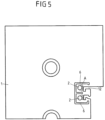
- the inlet area of the dry calibration 20 is shown on the left, and the outlet area of the extrusion nozzle 60 with the outlet plate 1 is shown on the right.
- the plastic material moves through the flow channel 3 of the extrusion nozzle 60, then briefly freely in space, and on the left it enters the dry calibration 2.
- the plastic melt strand jumps up by about 20% after leaving the extrusion nozzle 60 (ie the extruded plastic profile 10 widens, as in 13, 14 and 15 is shown schematically), which is compared to the average flow rate in the extrusion die 60 is due to slower withdrawal rate.
- a temperature control channel 2 for locally influencing the wall thickness of the plastic melt strand 10 is shown in the outlet plate 1A.
- air at room temperature is applied to temperature control channel 2; the tempering channel 2 is therefore used for cooling.
- the air throughput through the temperature control channel 2 can be adjusted via a throttle device 30, e.g. a manually operated tap. When the throttle device 30 is closed, no air flows. The wall of the flow channel 3 for the plastic melt strand 10 is not actively cooled. A temperature equilibrium is established in the extrusion nozzle 30 and the local melt throughput in the region shown reaches its maximum.
- the response time is about 2 to 10 seconds, at most about 1 minute, ie the effect of a change in the temperature control can be observed very quickly and the new temperature equilibrium of the extrusion nozzle 60 is established comparatively quickly a. If a suitable setting is found, i.e. the local throughput in the respective segment to the target range introduced, production runs stably over a long period of time as long as no disturbances occur.
- the wall thickness and/or the degree of filling in a specific profile section 11 is the control variable and the input variables of the temperature control device 2, e.g. the position of the throttle valve in the throttle device 30 and/or the temperature of the temperature control medium are the control variables.
- the manipulated variables then act on the temperature of the duct wall and thus on the throughput or the flow rate.
- a temperature control device 2 is shown in which, in the simplest case, the temperature in the flow channel wall, ie the wall area A, can be changed by manually adjusting a throttle device 30 .
- the wall thickness of the plastic profile 10 is visually observed or measured by a suitable measuring device 40 .
- the flow restrictor 30 is adjusted by hand so that the profile section 11 has the desired thickness. Extrusion can then take place over a longer period of time without continuous observation or measurement, i.e. without further adjustment of the flow restrictor.
- an automatic control circuit can be formed.
- the measuring device 40 measures a characteristic dimension (wall thickness, air gap and/or bulge, etc.). If this dimension deviates from the target dimension, the control device 50 causes the flow restrictor to be adjusted. Measurement and adjustment take place continuously and automatically, which is why we speak of a regulation. Alternatively, instead of the throughput of the tempering medium, its temperature can also be adjusted.
- the control variable wall thickness can be recorded in different ways:
- the wall thickness can be measured directly by means of an ultrasonic, optical or laser measurement.
- the distance (air gap) between the plastic profile 10 and the calibrator wall can also be used as a measured variable, for which the measurement methods mentioned can also be used.
- the measurement methods can also be used in combination with one another.
- a differential pressure for example the back pressure when the air gap is subjected to a certain initial pressure, can also be used as a measurement signal that can be generated comparatively easily.
- the measurement signal, the back pressure changes with the gap width (see e.g 14 ), which is available for the outflow of the tempering medium (e.g. air): If the material is directly adjacent to an outlet opening 15 for the measuring air, this is closed and the back pressure reaches its maximum. If the gap becomes larger, the dynamic pressure decreases.
- the tempering medium e.g. air
- a mechanical measurement is also well suited as a measurement variable: a measuring probe rests on the surface of the plastic profile 10 and measures wall thickness fluctuations. - In principle, it is not at all necessary to know the exact numerical values for the wall thickness. In the end, it is only important to maintain a state that is defined as permissible or optimal through the control.
- the measured variable is the back pressure in the inlet-side air gap 17 of the dry calibration 20.
- the wall thickness of the profile section 11 is recorded indirectly. If the gap 17 between the plastic profile 10 and the calibrator wall is subjected to a slight excess pressure (less than 1 bar, usually less than 0.2 bar), a back pressure is created. This back pressure is all the greater, the smaller the gap, ie the greater the wall thickness of the plastic profile 10 is. This back pressure is applied to an actuator which changes the throughput of the tempering medium in the desired direction.
- a slide can be used as an actuator, which influences the flow rate of the tempering medium.
- the extrusion nozzle 60 is adjusted in such a way that in the initial state the target wall thickness is reached when the flow rate through the temperature control channel 2 is partially throttled by the slide. A sufficiently large control margin is thus available.
- An air flow 16 is applied to both the temperature control channel 2 and the outlet opening 15 for the measurement air.
- the desired thickness is set by manually adjusting the throttle device 30, then the control is activated.
- the throttle 30 is adjusted as a result of the pressure or directly by this pressure until the pressure is the same as when the regulation was activated.
- Complex control with a computer is not required.
- the throttle device 30 can be used for this purpose be constructed similar to a servo valve. No electrical signal is required for the control, the adjustment is made by the flowing medium itself.
- the back pressure is used indirectly as a measurement signal, the larger the gap, the smaller the back pressure.
- the profile section 11 in the exit plate 1 of the extrusion nozzle 60 is to be cooled as the wall thickness increases, ie the gap at the measuring point decreases and the back pressure increases. That is, the throughput of the cooling air as a temperature medium must be increased, the actuator must open.
- the actuator must reduce the throughput in response to the decreasing back pressure, i.e. close it.
- the initial position of the actuator can be set manually, e.g. via an adjusting screw which is arranged between the automatic adjustment and the actual actuator, the slide.
- the outlined controlled system can be adjusted with the simplest tools with regard to the response behavior.
- blower Various controlled systems can be acted upon in parallel by a single air supply in the form of a blower. Because a comparatively small blower (motor power 300 W, maximum pressure +0.2 bar (for comparison Household vacuum cleaner: Motor power 1.8 kW, maximum suction pressure -0.2 bar)) is sufficient to be able to control up to 10 segments, whereby even then the entire blower power does not have to flow through the temperature control channels 2, there is no risk of mutual interference or there is no risk of it .only tolerably small.
- motor power 300 W, maximum pressure +0.2 bar for comparison Household vacuum cleaner: Motor power 1.8 kW, maximum suction pressure -0.2 bar
- the back pressure when an air gap 17 is acted upon in the dry calibration 20 is used as the measured variable.
- the measuring point 15 to which the measuring air flow 16 is applied is now approximately in the central area of the first dry calibration 20 (counted in the extrusion direction E).
- the correct shaping of the profile segment 11 can initially be set manually. A certain back pressure then corresponds to this state. If the control is then activated, this back pressure is automatically maintained.
- an actuator in this example a throttle element 30, is acted upon, as a result of which the air throughput through the temperature control channel 2 is changed.
- the flow cross section in the throttle element 30 is increased or decreased until the back pressure is again at the starting level when the control is activated.
- This invention is not limited to window profiles made of PVC or other profiles made of any plastic.
- the wall area, in which the local temperature control takes place extends predominantly in the width and less in the length (i.e. along the extrusion direction E). Also, the temperature control medium does not flow in the direction of extrusion E, but transversely to it, i.e. in the plane of the plate.
- the increase in temperature in the outlet area of the nozzle leads to an increase in the gloss of the surface. It is therefore advantageous to superheat the exit area of the nozzle above the nozzle temperature.
- the wall area of the flow channel A to be temperature-controlled covers the entire width of an outer wall of the plastic profile 10.
- the temperature control channel has a greater extent transversely to the extrusion direction E and a smaller extent in the extrusion direction E.
- a temperature increase in the wall area should not lead to a very significant increase in wall thickness.
- Predominantly only the outermost surface of the melt should be heated, as this also increases the gloss on the surface of the exiting profile, which is desirable for some applications. Conversely, the gloss can also be reduced somewhat by using a lower temperature.
- the temperature control channel 2 for influencing the flow channel wall temperature is only arranged in the nozzle outlet plate 1A and has an extension in the extrusion direction, parallel to the flow channel surface, of at least about 5 mm, and the upper limit is the thickness of the nozzle plate 1A, preferably about 6 to 10mm
- the inlet and outlet 9 for the temperature control medium are preferably in a plane parallel to the plane of the plate, the temperature control medium flows through the temperature control channel essentially transversely to the extrusion direction E.
- a nozzle plate 1 is shown in detail, these being provided with two local temperature control devices 2, as has already been described in connection with the other exemplary embodiments.
- Two inlets 9 for the temperature control medium to the local temperature control devices 2 are shown in the section shown.
- Figure 19A is the cut according to 18 shown in a perspective view.
- Figure 19B an enlarged section Figure 19A shown in the area of the local temperature control device 2 .
- the inlets 9 for the tempering medium have a thermal insulating device 70 which ensures increased heat transfer resistance along the inlet 9 .
- the thermal Insulator 70 on an air gap.
- the bore for the actual inlet 9 is dimensioned somewhat larger, so that a temperature-resistant plastic hose or a metal tube can be arranged in the bore as a fluid line 71 .
- the fluid line 71 has a smaller diameter than the surrounding bore, so that an air gap around the fluid line 71 is formed.
- the temperature control medium flows through the fluid line 71 to the local temperature control device 2 (see in particular Figure 19B ).
- the air gap 70 thermally insulates the fluid line 71 from the environment, i.e. the nozzle plate. This makes the heat exchange between the heat transfer liquid and the nozzle plate more difficult, so that the heat transfer liquid is exposed to fewer temperature losses.
- the local temperature control device 2 At the actual point of action, i.e. the local temperature control device 2, there is a higher temperature gradient than when no insulating device 70 is used. This allows the temperature change on the nozzle wall to be efficiently controlled and regulated.
- the temperature field of the nozzle plate 1 changes. This can take between 5 and 30 minutes, for example, which is relatively long.
- the thermal insulation device 70 better insulates the nozzle plate 1 against thermal influences from the tempering fluid.
- the thermal insulation device 70 is formed by an air gap.
- the thermal insulation device can also be designed differently. It is thus possible to place a temperature-coated plastic tube as a fluid line 71 in a bore of the inlet 9 without an air gap. If the wall is thick enough and/or the plastic material has sufficiently poor thermal conductivity, the air gap is irrelevant.
- thermal insulation means can also be used, e.g. an air gap 70 in which an insulated metal pipe is arranged.
- This embodiment with a thermal isolation device 70 can be used with all other described embodiments.
- Example 1 Extrusion device for the extrusion of plastic profiles (10), in particular a die plate (1), with at least one flow channel (3, 12) for plastic melt, characterized in that at least one wall area (A) of the flow channel (3, 12) with a local temperature control device (2) can be temperature-controlled in a targeted manner to adjust the flow rate of the plastic melt.
- Example 2 Extrusion device according to example 1, characterized in that the at least one wall area (A) of the flow channel (3, 12) is heated up to 30°C above or below the mean temperature of an extrusion die (60).
- Example 3 Example 3
- Extrusion device characterized in that the local temperature control device (2) is arranged in close proximity to at least one wall area (A) of the flow channel (3, 12), in particular in the vicinity of the outlet opening of the extrusion nozzle (60).
- example 4 Extrusion device according to at least one of the preceding examples, characterized in that the at least one wall area (A) to be temperature-controlled is arranged between 0 and 100 mm upstream of the outlet of the extrusion die (60) and/or the at least one wall area (A) has a length dimension of approximately 20 to 80 mm and/or has a width dimension of about 3 to 20 mm.
- Example 5 Example 5
- Extrusion device characterized in that the at least one wall area (A) to be temperature-controlled is arranged in the die outlet plate (1A) immediately upstream of the outlet of the extrusion die (60) and the at least one wall area (A) has one dimension in the direction of extrusion from 5 to 20 mm, preferably 6 to 10 mm, and a dimension transverse to the extrusion direction of about 20 to 150 mm, preferably over the entire width of the associated profile surface.
- Example 6 Extrusion device according to at least one of the preceding examples, characterized in that the local temperature control device (2) has at least one temperature control channel, at least one electrical heating means, in particular an induction or resistance heater and/or at least one thermoelectric element.
- Example 7 Extrusion device according to at least one of the preceding examples, characterized in that the local temperature control device (2) has at least one temperature control channel, at least one electrical heating means, in particular an induction or resistance heater and/or at least one thermoelectric element.
- Extrusion device characterized in that at least one temperature control channel (2) of a Tempering medium, in particular room air, cold and/or heated air, a gas and/or a liquid can flow through, with a liquid flowing through in particular in a closed circuit and a gas flowing through in an open circuit.
- a temperature control channel (2) of a Tempering medium in particular room air, cold and/or heated air
- a gas and/or a liquid can flow through, with a liquid flowing through in particular in a closed circuit and a gas flowing through in an open circuit.
- example 8 Extrusion device according to example 7, characterized in that the cooled tempering medium has a temperature between -50 and 30°C in the case of gas and a temperature between 15 and 180°C in the case of liquid, with in particular only the exit zone of the extrusion die (60th ) is cooled.
- Example 9 Extrusion device according to example 7, characterized in that the heated tempering medium has a temperature of between 250 and 500°C in the case of gas and a temperature of between 200 and 280°C in the case of liquid, with in particular only the exit zone of the extrusion die (60) is heated.
- Example 10. Extrusion device according to at least one of Examples 6 to 9, characterized in that at least one temperature control channel (2) has a width extension corresponding to the width dimension of the associated wall area (A) of the flow channel (3, 12), and/or that the gap height of the at least one temperature control channel (2) between 0.3 to 5 mm, preferably up to 2 mm.
- Example 11 Extrusion device according to at least one of Examples 6 to 9, characterized in that at least one temperature control channel (2) has a width extension corresponding to the width dimension of the associated wall area (A) of the flow channel (3, 12), and/or that the gap height of the at least one temperature control channel (2) between 0.3 to 5 mm, preferably up to 2 mm.
- Extrusion device characterized in that the local temperature control device (2) is thermally insulated from the extrusion die (60), in particular a die plate (1) with an air gap (6) and/or by means of a heat-insulating intermediate layer, so that the surface of the flow channel (3, 12) higher temperature differences become effective.
- Example 12 the local temperature control device (2) is thermally insulated from the extrusion die (60), in particular a die plate (1) with an air gap (6) and/or by means of a heat-insulating intermediate layer, so that the surface of the flow channel (3, 12) higher temperature differences become effective.
- Example 12 Example 12
- Extrusion device characterized by the coupling to a control or regulating device (50) for controlling the local temperature control device (2) for influencing a wall thickness of the plastic profile (10), at least one measured variable being the wall thickness, the gap width in a Calibration device (20), a spatial expansion of the plastic profile (10) after leaving the extrusion nozzle (60) and / or a measured back pressure in the calibration device (20).
- Example 13 Extrusion device according to at least one of the preceding examples, characterized in that the flow rate, the flow rate, the pressure and/or the temperature of the tempering medium, in particular air, can be specifically adjusted before it enters the tempering device (2).
- Extrusion device characterized by a control or regulating device (50) for changing the temperature of the at least one wall area (A) of the flow channel (3, 12) over time, in particular for setting a slow, controlled temperature transition of 5 to 15 K/min.
- Example 15 Extrusion device according to at least one of the preceding examples, characterized by a throttle device (30) for targeted adjustment of the throughput of the tempering medium, wherein the throttle device (30) can be coupled in particular to a control or regulating device.
- Example 16 Extrusion device according to at least one of the preceding examples, characterized by a thermal insulation device (70) for the temperature control medium for at least a partial area in the nozzle plate (1).
- Extrusion device characterized in that the insulating device (70) has an air gap (71) and/or an insulating material.
- Example 18 Extrusion process for plastic profiles (10), with at least one flow channel (3, 12), in particular in a nozzle plate (1), for plastic melt, the plastic melt in at least one flow channel (3, 12) for adjusting the flow rate on at least one wall area (A ) of the flow channel (3, 12) is tempered by a local temperature control device (2).
- Example 19 Extrusion process according to Example 18, characterized in that the at least one Wall area (A) of the flow channel (3, 12) 30 ° C above or below the average temperature of the extrusion die (60) is heated.
- Example 20 Extrusion process for plastic profiles (10), with at least one flow channel (3, 12), in particular in a nozzle plate (1), for plastic melt, the plastic melt in at least one flow channel (3, 12) for adjusting the flow rate on at least one wall area (A ) of the flow channel (3, 12) is tempered by a local temperature
- Extrusion process according to example 18 or 19, characterized in that at least one temperature control channel (2) can be flowed through by a temperature control medium, in particular air at room temperature, cooled and/or heated air, a gas and/or a liquid, the flow through with a liquid in particular in a closed circuit and the gas flows through it in an open circuit.
- a temperature control medium in particular air at room temperature, cooled and/or heated air, a gas and/or a liquid
- Example 21 Extrusion method according to example 20, characterized in that the cooled tempering fluid, in particular gas, has a temperature between -50 and 30°C, in particular room temperature, in particular only the exit zone of the extrusion die (60) being tempered.
- Example 22 Example 22.
- Extrusion method characterized by controlling or regulating the actuation of the local temperature control device (2) for influencing a wall thickness of the plastic profile (10), with at least one measured variable being the wall thickness, the gap width in a calibration device (20), is a spatial expansion of the plastic profile (10) after leaving the extrusion die (60) and/or a measured back pressure in the calibration device (20).
- Example 23 Extrusion process according to at least one of Examples 18 to 22, characterized in that the flow rate, the flow rate, the pressure and/or the temperature of the temperature control medium, in particular air, is set in a targeted manner before it enters the temperature control device (2).
Applications Claiming Priority (3)
| Application Number | Priority Date | Filing Date | Title |
|---|---|---|---|
| DE102011007618A DE102011007618A1 (de) | 2011-04-18 | 2011-04-18 | Extrusionsvorrichtung und Verfahren zur Beeinflussung von Wanddicken eines extrudierten Kunststoffprofils |
| PCT/EP2012/057045 WO2012143373A1 (fr) | 2011-04-18 | 2012-04-18 | Dispositif d'extrusion et procédé pour influencer l'épaisseur de paroi d'un profilé en plastique extrudé |
| EP12720125.9A EP2699404B8 (fr) | 2011-04-18 | 2012-04-18 | Dispositif d'extrusion et procédé pour influencer l'épaisseur de paroi d'un profilé en plastique extrudé |
Related Parent Applications (2)
| Application Number | Title | Priority Date | Filing Date |
|---|---|---|---|
| EP12720125.9A Division-Into EP2699404B8 (fr) | 2011-04-18 | 2012-04-18 | Dispositif d'extrusion et procédé pour influencer l'épaisseur de paroi d'un profilé en plastique extrudé |
| EP12720125.9A Division EP2699404B8 (fr) | 2011-04-18 | 2012-04-18 | Dispositif d'extrusion et procédé pour influencer l'épaisseur de paroi d'un profilé en plastique extrudé |
Publications (2)
| Publication Number | Publication Date |
|---|---|
| EP4234205A2 true EP4234205A2 (fr) | 2023-08-30 |
| EP4234205A3 EP4234205A3 (fr) | 2023-10-25 |
Family
ID=46052721
Family Applications (2)
| Application Number | Title | Priority Date | Filing Date |
|---|---|---|---|
| EP23177320.1A Pending EP4234205A3 (fr) | 2011-04-18 | 2012-04-18 | Dispositif d'extrusion et procédé pour influencer l'épaisseur de paroi d'un profilé en plastique extrudé |
| EP12720125.9A Active EP2699404B8 (fr) | 2011-04-18 | 2012-04-18 | Dispositif d'extrusion et procédé pour influencer l'épaisseur de paroi d'un profilé en plastique extrudé |
Family Applications After (1)
| Application Number | Title | Priority Date | Filing Date |
|---|---|---|---|
| EP12720125.9A Active EP2699404B8 (fr) | 2011-04-18 | 2012-04-18 | Dispositif d'extrusion et procédé pour influencer l'épaisseur de paroi d'un profilé en plastique extrudé |
Country Status (8)
| Country | Link |
|---|---|
| US (1) | US9636861B2 (fr) |
| EP (2) | EP4234205A3 (fr) |
| CN (1) | CN103492154B (fr) |
| DE (1) | DE102011007618A1 (fr) |
| EA (1) | EA026249B1 (fr) |
| ES (1) | ES2954098T3 (fr) |
| PL (1) | PL2699404T3 (fr) |
| WO (1) | WO2012143373A1 (fr) |
Cited By (1)
| Publication number | Priority date | Publication date | Assignee | Title |
|---|---|---|---|---|
| US20210114259A1 (en) * | 2019-10-18 | 2021-04-22 | The Japan Steel Works, Ltd. | Strand manufacturing apparatus and pellet manufacturing apparatus |
Families Citing this family (12)
| Publication number | Priority date | Publication date | Assignee | Title |
|---|---|---|---|---|
| CN103817903A (zh) * | 2014-02-24 | 2014-05-28 | 上海阿丽贝塑料防腐设备有限公司 | 热塑性塑料挤出料带专用机头 |
| CN104589629A (zh) * | 2014-11-29 | 2015-05-06 | 东电化日东(上海)电能源有限公司 | 用于打乱挤出的薄膜铸片的厚度分布的方法和挤出模头 |
| US20180187802A1 (en) * | 2016-12-30 | 2018-07-05 | Polyflow Llc | Multi-layer pipes |
| DE102017003926A1 (de) | 2017-04-24 | 2018-10-25 | Heinz Gross | Extrusionsvorrichtung zur Minimierung des thermischen Abbaus von Schmelzen |
| CN109382997A (zh) * | 2018-12-07 | 2019-02-26 | 东莞市银禧光电材料科技股份有限公司 | 一种非等壁厚挤出型材用模具 |
| IT201900018920A1 (it) * | 2019-10-15 | 2021-04-15 | Tecno System Srl | Dispositivo per estrusione di materie plastiche con raffreddamento ad azoto e metodo di estrusione |
| DE102019215876A1 (de) * | 2019-10-15 | 2021-04-15 | Greiner Extrusion Group Gmbh | Extrusionsvorrichtung und Extrusionsverfahren |
| DE102019133360A1 (de) | 2019-12-06 | 2021-06-10 | Rehau Ag + Co | Verfahren zur Herstellung eines Kunststoff-Profils |
| DE102019133348A1 (de) * | 2019-12-06 | 2021-06-10 | Rehau Ag + Co | Verfahren zur Herstellung eines Kunststoff-Profils |
| CN111002561A (zh) * | 2019-12-31 | 2020-04-14 | 安徽耐科装备科技股份有限公司 | 多腔挤出异型材模头料流调控装置及调控方法 |
| JP6722834B1 (ja) * | 2020-03-19 | 2020-07-15 | 日東電工株式会社 | 押出方法 |
| CN114290712B (zh) * | 2022-01-24 | 2024-04-05 | 广东鑫球新材料科技有限公司 | 一种高精度温控的纤维棒加热成型装置 |
Family Cites Families (23)
| Publication number | Priority date | Publication date | Assignee | Title |
|---|---|---|---|---|
| FR942297A (fr) * | 1947-02-25 | 1949-02-03 | Procédé et appareil pour la production continue par refoulement de barres profilées en matière synthétique et produit obtenu par ce procédé | |
| FR2093170A5 (fr) * | 1970-06-04 | 1972-01-28 | Pont A Mousson | |
| DE2232930A1 (de) * | 1971-07-06 | 1973-02-01 | Hepworth Plastics Ltd | Verfahren und vorrichtung zur herstellung von rohren unbedingt gleichmaessiger wandstaerke im strangpressverfahren |
| NL7109900A (fr) | 1971-07-16 | 1973-01-18 | ||
| DE2535286C3 (de) * | 1975-08-07 | 1979-01-25 | Dynamit Nobel Ag, 5210 Troisdorf | Verfahren zum Kalibrieren einer coextrudierten Profilleiste aus thermoplastischen Kunststoffen |
| US4332543A (en) * | 1980-09-15 | 1982-06-01 | Monsanto Company | Extrusion die with melt flow control |
| US4541792A (en) * | 1983-05-09 | 1985-09-17 | Nrm Corporation | Dual loop temperature control system for rubber and other extruders with optional connection for heat pump |
| US4548570A (en) * | 1983-05-12 | 1985-10-22 | Cosden Technology, Inc. | Extrusion apparatus for producing thermoplastic pipe |
| NL8304451A (nl) * | 1983-12-27 | 1985-07-16 | Wavin Bv | Werkwijze en inrichting voor het regelen van de wanddikte van geextrudeerde kunststofbuis. |
| DE3503721C2 (de) * | 1985-02-05 | 1993-12-16 | Hoechst Ag | Breitschlitzdüse zum Extrudieren eines thermoplastischen Kunststoffes |
| WO1991012097A1 (fr) * | 1990-02-09 | 1991-08-22 | G James Australia Pty. Ltd. | Systeme de refroidissement pour filieres d'extrusion |
| DE19815276B4 (de) * | 1997-05-02 | 2010-04-08 | C.A. Greiner & Söhne Ges.m.b.H. | Nachbehandlungsverfahren für einen extrudierten Gegenstand |
| AT412771B (de) * | 1997-06-26 | 2005-07-25 | Greiner & Soehne C A | Extrusionswerkzeug für eine kunststoffschmelze |
| DE19823304B4 (de) * | 1998-05-25 | 2004-01-22 | Windmöller & Hölscher Kg | Vorrichtung zum Extrudieren von Kunststoff-Mehrschichtfolien, -platten oder -schläuchen |
| JP2000158514A (ja) * | 1998-11-26 | 2000-06-13 | Sekisui Chem Co Ltd | 押出成形用サイジング金型の製造方法 |
| DE19855751A1 (de) * | 1998-12-03 | 2000-06-08 | Hoechst Trespaphan Gmbh | Vorrichtung zur Spaltverstellung |
| AT3577U1 (de) * | 1999-01-28 | 2000-05-25 | Technoplast Kunststofftechnik | Vorrichtung zur extrusion von kunststoffprofilen |
| DE29912972U1 (de) * | 1999-07-24 | 1999-10-21 | Breuning Wolfgang | Extrusionswerkzeug |
| JP3893311B2 (ja) * | 2002-04-16 | 2007-03-14 | 鬼怒川ゴム工業株式会社 | 押出成形機の複合押出用口金構造 |
| AT414317B (de) * | 2004-11-15 | 2007-02-15 | Greiner Extrusionstechnik Gmbh | Formgebungseinrichtung sowie verfahren zur formgebung und abkühlung von hohlprofilen |
| AT507973B1 (de) * | 2005-03-16 | 2010-11-15 | Greiner Extrusionstechnik Gmbh | Traganordnung für ein extrusionswerkzeug sowie extrusionswerkzeug zur formgebung eines gegenstandes |
| DE102007030369B4 (de) * | 2007-06-29 | 2015-08-27 | Harald Feuerherm | Verfahren zur Herstellung blasgeformter Hohlkörper |
| DE102008047206A1 (de) | 2008-09-15 | 2010-04-15 | Cincinnati Extrusion Gmbh | Vorrichtung und Verfahren zum Vergleichmäßigen der Wandstärke beim Extrudieren von Kunststoffprofilen |
-
2011
- 2011-04-18 DE DE102011007618A patent/DE102011007618A1/de active Pending
-
2012
- 2012-04-18 US US14/112,094 patent/US9636861B2/en active Active
- 2012-04-18 PL PL12720125.9T patent/PL2699404T3/pl unknown
- 2012-04-18 EP EP23177320.1A patent/EP4234205A3/fr active Pending
- 2012-04-18 WO PCT/EP2012/057045 patent/WO2012143373A1/fr active Application Filing
- 2012-04-18 EA EA201301164A patent/EA026249B1/ru not_active IP Right Cessation
- 2012-04-18 CN CN201280019196.8A patent/CN103492154B/zh active Active
- 2012-04-18 EP EP12720125.9A patent/EP2699404B8/fr active Active
- 2012-04-18 ES ES12720125T patent/ES2954098T3/es active Active
Cited By (1)
| Publication number | Priority date | Publication date | Assignee | Title |
|---|---|---|---|---|
| US20210114259A1 (en) * | 2019-10-18 | 2021-04-22 | The Japan Steel Works, Ltd. | Strand manufacturing apparatus and pellet manufacturing apparatus |
Also Published As
| Publication number | Publication date |
|---|---|
| PL2699404T3 (pl) | 2023-10-30 |
| EP2699404B1 (fr) | 2023-06-07 |
| DE102011007618A1 (de) | 2012-10-18 |
| ES2954098T3 (es) | 2023-11-20 |
| CN103492154B (zh) | 2016-01-27 |
| US20140035189A1 (en) | 2014-02-06 |
| EP2699404C0 (fr) | 2023-06-07 |
| EA201301164A1 (ru) | 2014-11-28 |
| EP2699404B8 (fr) | 2023-07-19 |
| CN103492154A (zh) | 2014-01-01 |
| WO2012143373A1 (fr) | 2012-10-26 |
| EP4234205A3 (fr) | 2023-10-25 |
| EA026249B1 (ru) | 2017-03-31 |
| EP2699404A1 (fr) | 2014-02-26 |
| US9636861B2 (en) | 2017-05-02 |
Similar Documents
| Publication | Publication Date | Title |
|---|---|---|
| EP2699404B1 (fr) | Dispositif d'extrusion et procédé pour influencer l'épaisseur de paroi d'un profilé en plastique extrudé | |
| EP3527040B1 (fr) | Méthode et dispositif pour la fabrication de pièces moulées à partir de pièces semi-finies | |
| DE102007056121B3 (de) | Breitschlitzdüse und Anlage zum Beschichten mit thermoplastischem Beschichtungsmaterial | |
| WO2010084094A2 (fr) | Installation d'extrusion à dispositif de freinage pour la régulation de pression dynamique | |
| WO2019219730A1 (fr) | Procédé de régulation automatisé de la taille d'une fente d'un ensemble formant buse et système de commande et/ou de régulation | |
| DE10008994B4 (de) | Verfahren und Vorrichtung zum Herstellen von Keramikformen | |
| EP3793800A1 (fr) | Procédé de réglage automatisé de la grandeur d'une fente d'un agencement de buse et système de commande et/ou de réglage | |
| DE3503721C2 (de) | Breitschlitzdüse zum Extrudieren eines thermoplastischen Kunststoffes | |
| EP1346814B1 (fr) | Dispositif de calibration | |
| EP0505960A1 (fr) | Procédé et dispositif pour régler l'épaisseur d'un film | |
| WO2018103841A1 (fr) | Dispositif de thermorégulation pour thermoréguler un élément structural | |
| DE2341127A1 (de) | Verfahren und vorrichtung zur herstellung von polymer-folien | |
| EP1250992B1 (fr) | Procédé pour refroidir les deux moitiés du moule d'un outil de formage et unité de mélange pour la mise en oeuvre du procédé | |
| EP3529036A1 (fr) | Procédé et dispositif pour produire des profilés en matière plastique | |
| EP1834753A2 (fr) | Procédé de fonctionnement d'installations d'extrusion destinées à extruder des matières thermoplastiques | |
| DE102005042442A1 (de) | Extrusionsanlage mit zumindest einem Glättwerk zum Bearbeiten von extrudiertem Kunststoffmaterial | |
| DE2924269A1 (de) | Vorrichtung zur regelbaren aenderung des stroemungsquerschnittes in einem schneckenextruder | |
| EP3444098B1 (fr) | Procédé et dispositif de refroidissement d'un outil d'une machine de thermoformage comprenant deux moitiés d'outil | |
| AT519152B1 (de) | Einspritzeinheit | |
| DE1291896B (de) | Gekuehlte Kalibrierduese in Strangpressanlagen fuer Profile aus thermoplastischem Kunststoff | |
| DE102010037091B4 (de) | Vorrichtung zur Post-Coextrusion und Verwendung der Vorrichtung | |
| EP3508338A1 (fr) | Dispositif de pression permettant d'obtenir des produits contenant des biopolymères en évitant la dénaturation d'une matière à presser | |
| DE10356711A1 (de) | Bandsiebwechsler | |
| EP3825093A1 (fr) | Buse d'extrusion destinée à la fabrication d'un profilé en matière plastique | |
| DE60219252T2 (de) | Temperaturgeregelte Extrusionsdüse für Extrusion von Schlauchfolien |
Legal Events
| Date | Code | Title | Description |
|---|---|---|---|
| PUAI | Public reference made under article 153(3) epc to a published international application that has entered the european phase |
Free format text: ORIGINAL CODE: 0009012 |
|
| STAA | Information on the status of an ep patent application or granted ep patent |
Free format text: STATUS: THE APPLICATION HAS BEEN PUBLISHED |
|
| AC | Divisional application: reference to earlier application |
Ref document number: 2699404 Country of ref document: EP Kind code of ref document: P |
|
| AK | Designated contracting states |
Kind code of ref document: A2 Designated state(s): AL AT BE BG CH CY CZ DE DK EE ES FI FR GB GR HR HU IE IS IT LI LT LU LV MC MK MT NL NO PL PT RO RS SE SI SK SM TR |
|
| REG | Reference to a national code |
Ref country code: DE Ref legal event code: R079 Free format text: PREVIOUS MAIN CLASS: B29C0048120000 Ipc: B29C0048110000 |
|
| PUAL | Search report despatched |
Free format text: ORIGINAL CODE: 0009013 |
|
| AK | Designated contracting states |
Kind code of ref document: A3 Designated state(s): AL AT BE BG CH CY CZ DE DK EE ES FI FR GB GR HR HU IE IS IT LI LT LU LV MC MK MT NL NO PL PT RO RS SE SI SK SM TR |
|
| RIC1 | Information provided on ipc code assigned before grant |
Ipc: B29C 48/90 20190101ALN20230915BHEP Ipc: B29C 48/92 20190101ALI20230915BHEP Ipc: B29C 48/30 20190101ALI20230915BHEP Ipc: B29C 48/12 20190101ALI20230915BHEP Ipc: B29C 48/11 20190101AFI20230915BHEP |
|
| RAP1 | Party data changed (applicant data changed or rights of an application transferred) |
Owner name: EXELLIQ AUSTRIA GMBH |
|
| STAA | Information on the status of an ep patent application or granted ep patent |
Free format text: STATUS: REQUEST FOR EXAMINATION WAS MADE |