EP4234205A2 - Extrusion device and method for influencing wall thicknesses of an extruded plastic profile - Google Patents
Extrusion device and method for influencing wall thicknesses of an extruded plastic profile Download PDFInfo
- Publication number
- EP4234205A2 EP4234205A2 EP23177320.1A EP23177320A EP4234205A2 EP 4234205 A2 EP4234205 A2 EP 4234205A2 EP 23177320 A EP23177320 A EP 23177320A EP 4234205 A2 EP4234205 A2 EP 4234205A2
- Authority
- EP
- European Patent Office
- Prior art keywords
- extrusion
- temperature
- temperature control
- plastic
- wall
- Prior art date
- Legal status (The legal status is an assumption and is not a legal conclusion. Google has not performed a legal analysis and makes no representation as to the accuracy of the status listed.)
- Pending
Links
- 238000001125 extrusion Methods 0.000 title claims abstract description 205
- 238000000034 method Methods 0.000 title claims abstract description 24
- 239000003000 extruded plastic Substances 0.000 title description 10
- 239000004033 plastic Substances 0.000 claims abstract description 138
- 229920003023 plastic Polymers 0.000 claims abstract description 138
- 230000008569 process Effects 0.000 claims abstract description 15
- 238000005496 tempering Methods 0.000 claims description 44
- 230000008859 change Effects 0.000 claims description 28
- 230000033228 biological regulation Effects 0.000 claims description 12
- 238000011144 upstream manufacturing Methods 0.000 claims description 12
- 230000001105 regulatory effect Effects 0.000 claims description 11
- 230000001276 controlling effect Effects 0.000 claims description 5
- 230000008878 coupling Effects 0.000 claims description 3
- 238000010168 coupling process Methods 0.000 claims description 3
- 238000005859 coupling reaction Methods 0.000 claims description 3
- 239000011810 insulating material Substances 0.000 claims description 3
- 230000007704 transition Effects 0.000 claims description 3
- 238000001816 cooling Methods 0.000 description 24
- 238000010438 heat treatment Methods 0.000 description 22
- 230000000694 effects Effects 0.000 description 21
- 239000000155 melt Substances 0.000 description 17
- 239000007789 gas Substances 0.000 description 16
- 239000012530 fluid Substances 0.000 description 15
- 239000007788 liquid Substances 0.000 description 15
- 238000005259 measurement Methods 0.000 description 13
- 239000000463 material Substances 0.000 description 8
- 230000002093 peripheral effect Effects 0.000 description 8
- 238000009413 insulation Methods 0.000 description 7
- 238000004519 manufacturing process Methods 0.000 description 7
- 230000009467 reduction Effects 0.000 description 6
- 238000012546 transfer Methods 0.000 description 4
- 229910000831 Steel Inorganic materials 0.000 description 3
- 238000013461 design Methods 0.000 description 3
- 239000010410 layer Substances 0.000 description 3
- 230000004044 response Effects 0.000 description 3
- 238000007493 shaping process Methods 0.000 description 3
- 239000010959 steel Substances 0.000 description 3
- 230000008719 thickening Effects 0.000 description 3
- RYGMFSIKBFXOCR-UHFFFAOYSA-N Copper Chemical compound [Cu] RYGMFSIKBFXOCR-UHFFFAOYSA-N 0.000 description 2
- 230000008901 benefit Effects 0.000 description 2
- 229910052802 copper Inorganic materials 0.000 description 2
- 239000010949 copper Substances 0.000 description 2
- 230000007423 decrease Effects 0.000 description 2
- 230000003247 decreasing effect Effects 0.000 description 2
- 238000006073 displacement reaction Methods 0.000 description 2
- 230000006698 induction Effects 0.000 description 2
- 239000012212 insulator Substances 0.000 description 2
- 230000003993 interaction Effects 0.000 description 2
- 238000000691 measurement method Methods 0.000 description 2
- 239000002184 metal Substances 0.000 description 2
- 229910052751 metal Inorganic materials 0.000 description 2
- 238000007789 sealing Methods 0.000 description 2
- 206010013710 Drug interaction Diseases 0.000 description 1
- 240000003517 Elaeocarpus dentatus Species 0.000 description 1
- 230000005679 Peltier effect Effects 0.000 description 1
- 230000009471 action Effects 0.000 description 1
- 230000004913 activation Effects 0.000 description 1
- 238000013459 approach Methods 0.000 description 1
- 230000015572 biosynthetic process Effects 0.000 description 1
- 238000006243 chemical reaction Methods 0.000 description 1
- 239000007795 chemical reaction product Substances 0.000 description 1
- 238000011109 contamination Methods 0.000 description 1
- 239000002826 coolant Substances 0.000 description 1
- 238000005520 cutting process Methods 0.000 description 1
- 230000001419 dependent effect Effects 0.000 description 1
- 238000001514 detection method Methods 0.000 description 1
- 238000009826 distribution Methods 0.000 description 1
- 230000003628 erosive effect Effects 0.000 description 1
- 238000002474 experimental method Methods 0.000 description 1
- 238000011049 filling Methods 0.000 description 1
- 238000009472 formulation Methods 0.000 description 1
- 230000017525 heat dissipation Effects 0.000 description 1
- 239000012535 impurity Substances 0.000 description 1
- 238000009434 installation Methods 0.000 description 1
- 238000002955 isolation Methods 0.000 description 1
- 238000011068 loading method Methods 0.000 description 1
- 239000000314 lubricant Substances 0.000 description 1
- 238000011326 mechanical measurement Methods 0.000 description 1
- 238000003801 milling Methods 0.000 description 1
- 238000002156 mixing Methods 0.000 description 1
- 239000000203 mixture Substances 0.000 description 1
- 239000003921 oil Substances 0.000 description 1
- 230000003287 optical effect Effects 0.000 description 1
- 239000002245 particle Substances 0.000 description 1
- 230000000149 penetrating effect Effects 0.000 description 1
- 238000003825 pressing Methods 0.000 description 1
- 239000000047 product Substances 0.000 description 1
- 239000000523 sample Substances 0.000 description 1
- 239000012791 sliding layer Substances 0.000 description 1
- 238000007669 thermal treatment Methods 0.000 description 1
- 230000001960 triggered effect Effects 0.000 description 1
- XLYOFNOQVPJJNP-UHFFFAOYSA-N water Substances O XLYOFNOQVPJJNP-UHFFFAOYSA-N 0.000 description 1
Images


Classifications
-
- B—PERFORMING OPERATIONS; TRANSPORTING
- B29—WORKING OF PLASTICS; WORKING OF SUBSTANCES IN A PLASTIC STATE IN GENERAL
- B29C—SHAPING OR JOINING OF PLASTICS; SHAPING OF MATERIAL IN A PLASTIC STATE, NOT OTHERWISE PROVIDED FOR; AFTER-TREATMENT OF THE SHAPED PRODUCTS, e.g. REPAIRING
- B29C48/00—Extrusion moulding, i.e. expressing the moulding material through a die or nozzle which imparts the desired form; Apparatus therefor
- B29C48/25—Component parts, details or accessories; Auxiliary operations
- B29C48/30—Extrusion nozzles or dies
- B29C48/32—Extrusion nozzles or dies with annular openings, e.g. for forming tubular articles
- B29C48/335—Multiple annular extrusion nozzles in coaxial arrangement, e.g. for making multi-layered tubular articles
- B29C48/336—Multiple annular extrusion nozzles in coaxial arrangement, e.g. for making multi-layered tubular articles the components merging one by one down streams in the die
- B29C48/3363—Multiple annular extrusion nozzles in coaxial arrangement, e.g. for making multi-layered tubular articles the components merging one by one down streams in the die using a layered die, e.g. stacked discs
-
- B—PERFORMING OPERATIONS; TRANSPORTING
- B29—WORKING OF PLASTICS; WORKING OF SUBSTANCES IN A PLASTIC STATE IN GENERAL
- B29C—SHAPING OR JOINING OF PLASTICS; SHAPING OF MATERIAL IN A PLASTIC STATE, NOT OTHERWISE PROVIDED FOR; AFTER-TREATMENT OF THE SHAPED PRODUCTS, e.g. REPAIRING
- B29C48/00—Extrusion moulding, i.e. expressing the moulding material through a die or nozzle which imparts the desired form; Apparatus therefor
- B29C48/25—Component parts, details or accessories; Auxiliary operations
- B29C48/92—Measuring, controlling or regulating
-
- B—PERFORMING OPERATIONS; TRANSPORTING
- B29—WORKING OF PLASTICS; WORKING OF SUBSTANCES IN A PLASTIC STATE IN GENERAL
- B29C—SHAPING OR JOINING OF PLASTICS; SHAPING OF MATERIAL IN A PLASTIC STATE, NOT OTHERWISE PROVIDED FOR; AFTER-TREATMENT OF THE SHAPED PRODUCTS, e.g. REPAIRING
- B29C48/00—Extrusion moulding, i.e. expressing the moulding material through a die or nozzle which imparts the desired form; Apparatus therefor
- B29C48/03—Extrusion moulding, i.e. expressing the moulding material through a die or nozzle which imparts the desired form; Apparatus therefor characterised by the shape of the extruded material at extrusion
- B29C48/09—Articles with cross-sections having partially or fully enclosed cavities, e.g. pipes or channels
- B29C48/11—Articles with cross-sections having partially or fully enclosed cavities, e.g. pipes or channels comprising two or more partially or fully enclosed cavities, e.g. honeycomb-shaped
-
- B—PERFORMING OPERATIONS; TRANSPORTING
- B29—WORKING OF PLASTICS; WORKING OF SUBSTANCES IN A PLASTIC STATE IN GENERAL
- B29C—SHAPING OR JOINING OF PLASTICS; SHAPING OF MATERIAL IN A PLASTIC STATE, NOT OTHERWISE PROVIDED FOR; AFTER-TREATMENT OF THE SHAPED PRODUCTS, e.g. REPAIRING
- B29C48/00—Extrusion moulding, i.e. expressing the moulding material through a die or nozzle which imparts the desired form; Apparatus therefor
- B29C48/03—Extrusion moulding, i.e. expressing the moulding material through a die or nozzle which imparts the desired form; Apparatus therefor characterised by the shape of the extruded material at extrusion
- B29C48/12—Articles with an irregular circumference when viewed in cross-section, e.g. window profiles
-
- B—PERFORMING OPERATIONS; TRANSPORTING
- B29—WORKING OF PLASTICS; WORKING OF SUBSTANCES IN A PLASTIC STATE IN GENERAL
- B29C—SHAPING OR JOINING OF PLASTICS; SHAPING OF MATERIAL IN A PLASTIC STATE, NOT OTHERWISE PROVIDED FOR; AFTER-TREATMENT OF THE SHAPED PRODUCTS, e.g. REPAIRING
- B29C48/00—Extrusion moulding, i.e. expressing the moulding material through a die or nozzle which imparts the desired form; Apparatus therefor
- B29C48/15—Extrusion moulding, i.e. expressing the moulding material through a die or nozzle which imparts the desired form; Apparatus therefor incorporating preformed parts or layers, e.g. extrusion moulding around inserts
- B29C48/151—Coating hollow articles
-
- B—PERFORMING OPERATIONS; TRANSPORTING
- B29—WORKING OF PLASTICS; WORKING OF SUBSTANCES IN A PLASTIC STATE IN GENERAL
- B29C—SHAPING OR JOINING OF PLASTICS; SHAPING OF MATERIAL IN A PLASTIC STATE, NOT OTHERWISE PROVIDED FOR; AFTER-TREATMENT OF THE SHAPED PRODUCTS, e.g. REPAIRING
- B29C48/00—Extrusion moulding, i.e. expressing the moulding material through a die or nozzle which imparts the desired form; Apparatus therefor
- B29C48/25—Component parts, details or accessories; Auxiliary operations
- B29C48/30—Extrusion nozzles or dies
- B29C48/3001—Extrusion nozzles or dies characterised by the material or their manufacturing process
-
- B—PERFORMING OPERATIONS; TRANSPORTING
- B29—WORKING OF PLASTICS; WORKING OF SUBSTANCES IN A PLASTIC STATE IN GENERAL
- B29C—SHAPING OR JOINING OF PLASTICS; SHAPING OF MATERIAL IN A PLASTIC STATE, NOT OTHERWISE PROVIDED FOR; AFTER-TREATMENT OF THE SHAPED PRODUCTS, e.g. REPAIRING
- B29C48/00—Extrusion moulding, i.e. expressing the moulding material through a die or nozzle which imparts the desired form; Apparatus therefor
- B29C48/25—Component parts, details or accessories; Auxiliary operations
- B29C48/78—Thermal treatment of the extrusion moulding material or of preformed parts or layers, e.g. by heating or cooling
- B29C48/86—Thermal treatment of the extrusion moulding material or of preformed parts or layers, e.g. by heating or cooling at the nozzle zone
- B29C48/865—Heating
-
- B—PERFORMING OPERATIONS; TRANSPORTING
- B29—WORKING OF PLASTICS; WORKING OF SUBSTANCES IN A PLASTIC STATE IN GENERAL
- B29C—SHAPING OR JOINING OF PLASTICS; SHAPING OF MATERIAL IN A PLASTIC STATE, NOT OTHERWISE PROVIDED FOR; AFTER-TREATMENT OF THE SHAPED PRODUCTS, e.g. REPAIRING
- B29C48/00—Extrusion moulding, i.e. expressing the moulding material through a die or nozzle which imparts the desired form; Apparatus therefor
- B29C48/25—Component parts, details or accessories; Auxiliary operations
- B29C48/78—Thermal treatment of the extrusion moulding material or of preformed parts or layers, e.g. by heating or cooling
- B29C48/86—Thermal treatment of the extrusion moulding material or of preformed parts or layers, e.g. by heating or cooling at the nozzle zone
- B29C48/87—Cooling
-
- B—PERFORMING OPERATIONS; TRANSPORTING
- B29—WORKING OF PLASTICS; WORKING OF SUBSTANCES IN A PLASTIC STATE IN GENERAL
- B29C—SHAPING OR JOINING OF PLASTICS; SHAPING OF MATERIAL IN A PLASTIC STATE, NOT OTHERWISE PROVIDED FOR; AFTER-TREATMENT OF THE SHAPED PRODUCTS, e.g. REPAIRING
- B29C48/00—Extrusion moulding, i.e. expressing the moulding material through a die or nozzle which imparts the desired form; Apparatus therefor
- B29C48/25—Component parts, details or accessories; Auxiliary operations
- B29C48/78—Thermal treatment of the extrusion moulding material or of preformed parts or layers, e.g. by heating or cooling
- B29C48/86—Thermal treatment of the extrusion moulding material or of preformed parts or layers, e.g. by heating or cooling at the nozzle zone
- B29C48/872—Thermal treatment of the extrusion moulding material or of preformed parts or layers, e.g. by heating or cooling at the nozzle zone characterised by differential heating or cooling
-
- B—PERFORMING OPERATIONS; TRANSPORTING
- B29—WORKING OF PLASTICS; WORKING OF SUBSTANCES IN A PLASTIC STATE IN GENERAL
- B29C—SHAPING OR JOINING OF PLASTICS; SHAPING OF MATERIAL IN A PLASTIC STATE, NOT OTHERWISE PROVIDED FOR; AFTER-TREATMENT OF THE SHAPED PRODUCTS, e.g. REPAIRING
- B29C2948/00—Indexing scheme relating to extrusion moulding
- B29C2948/92—Measuring, controlling or regulating
- B29C2948/92009—Measured parameter
- B29C2948/92114—Dimensions
- B29C2948/92152—Thickness
-
- B—PERFORMING OPERATIONS; TRANSPORTING
- B29—WORKING OF PLASTICS; WORKING OF SUBSTANCES IN A PLASTIC STATE IN GENERAL
- B29C—SHAPING OR JOINING OF PLASTICS; SHAPING OF MATERIAL IN A PLASTIC STATE, NOT OTHERWISE PROVIDED FOR; AFTER-TREATMENT OF THE SHAPED PRODUCTS, e.g. REPAIRING
- B29C2948/00—Indexing scheme relating to extrusion moulding
- B29C2948/92—Measuring, controlling or regulating
- B29C2948/92504—Controlled parameter
- B29C2948/9258—Velocity
- B29C2948/926—Flow or feed rate
-
- B—PERFORMING OPERATIONS; TRANSPORTING
- B29—WORKING OF PLASTICS; WORKING OF SUBSTANCES IN A PLASTIC STATE IN GENERAL
- B29C—SHAPING OR JOINING OF PLASTICS; SHAPING OF MATERIAL IN A PLASTIC STATE, NOT OTHERWISE PROVIDED FOR; AFTER-TREATMENT OF THE SHAPED PRODUCTS, e.g. REPAIRING
- B29C2948/00—Indexing scheme relating to extrusion moulding
- B29C2948/92—Measuring, controlling or regulating
- B29C2948/92504—Controlled parameter
- B29C2948/92609—Dimensions
- B29C2948/92647—Thickness
-
- B—PERFORMING OPERATIONS; TRANSPORTING
- B29—WORKING OF PLASTICS; WORKING OF SUBSTANCES IN A PLASTIC STATE IN GENERAL
- B29C—SHAPING OR JOINING OF PLASTICS; SHAPING OF MATERIAL IN A PLASTIC STATE, NOT OTHERWISE PROVIDED FOR; AFTER-TREATMENT OF THE SHAPED PRODUCTS, e.g. REPAIRING
- B29C2948/00—Indexing scheme relating to extrusion moulding
- B29C2948/92—Measuring, controlling or regulating
- B29C2948/92504—Controlled parameter
- B29C2948/92609—Dimensions
- B29C2948/92666—Distortion, shrinkage, dilatation, swell or warpage
-
- B—PERFORMING OPERATIONS; TRANSPORTING
- B29—WORKING OF PLASTICS; WORKING OF SUBSTANCES IN A PLASTIC STATE IN GENERAL
- B29C—SHAPING OR JOINING OF PLASTICS; SHAPING OF MATERIAL IN A PLASTIC STATE, NOT OTHERWISE PROVIDED FOR; AFTER-TREATMENT OF THE SHAPED PRODUCTS, e.g. REPAIRING
- B29C2948/00—Indexing scheme relating to extrusion moulding
- B29C2948/92—Measuring, controlling or regulating
- B29C2948/92504—Controlled parameter
- B29C2948/92695—Viscosity; Melt flow index [MFI]; Molecular weight
-
- B—PERFORMING OPERATIONS; TRANSPORTING
- B29—WORKING OF PLASTICS; WORKING OF SUBSTANCES IN A PLASTIC STATE IN GENERAL
- B29C—SHAPING OR JOINING OF PLASTICS; SHAPING OF MATERIAL IN A PLASTIC STATE, NOT OTHERWISE PROVIDED FOR; AFTER-TREATMENT OF THE SHAPED PRODUCTS, e.g. REPAIRING
- B29C2948/00—Indexing scheme relating to extrusion moulding
- B29C2948/92—Measuring, controlling or regulating
- B29C2948/92504—Controlled parameter
- B29C2948/92704—Temperature
-
- B—PERFORMING OPERATIONS; TRANSPORTING
- B29—WORKING OF PLASTICS; WORKING OF SUBSTANCES IN A PLASTIC STATE IN GENERAL
- B29C—SHAPING OR JOINING OF PLASTICS; SHAPING OF MATERIAL IN A PLASTIC STATE, NOT OTHERWISE PROVIDED FOR; AFTER-TREATMENT OF THE SHAPED PRODUCTS, e.g. REPAIRING
- B29C2948/00—Indexing scheme relating to extrusion moulding
- B29C2948/92—Measuring, controlling or regulating
- B29C2948/92819—Location or phase of control
- B29C2948/92857—Extrusion unit
- B29C2948/92904—Die; Nozzle zone
-
- B—PERFORMING OPERATIONS; TRANSPORTING
- B29—WORKING OF PLASTICS; WORKING OF SUBSTANCES IN A PLASTIC STATE IN GENERAL
- B29C—SHAPING OR JOINING OF PLASTICS; SHAPING OF MATERIAL IN A PLASTIC STATE, NOT OTHERWISE PROVIDED FOR; AFTER-TREATMENT OF THE SHAPED PRODUCTS, e.g. REPAIRING
- B29C48/00—Extrusion moulding, i.e. expressing the moulding material through a die or nozzle which imparts the desired form; Apparatus therefor
- B29C48/25—Component parts, details or accessories; Auxiliary operations
- B29C48/88—Thermal treatment of the stream of extruded material, e.g. cooling
- B29C48/90—Thermal treatment of the stream of extruded material, e.g. cooling with calibration or sizing, i.e. combined with fixing or setting of the final dimensions of the extruded article
- B29C48/904—Thermal treatment of the stream of extruded material, e.g. cooling with calibration or sizing, i.e. combined with fixing or setting of the final dimensions of the extruded article using dry calibration, i.e. no quenching tank, e.g. with water spray for cooling or lubrication
-
- B—PERFORMING OPERATIONS; TRANSPORTING
- B29—WORKING OF PLASTICS; WORKING OF SUBSTANCES IN A PLASTIC STATE IN GENERAL
- B29C—SHAPING OR JOINING OF PLASTICS; SHAPING OF MATERIAL IN A PLASTIC STATE, NOT OTHERWISE PROVIDED FOR; AFTER-TREATMENT OF THE SHAPED PRODUCTS, e.g. REPAIRING
- B29C48/00—Extrusion moulding, i.e. expressing the moulding material through a die or nozzle which imparts the desired form; Apparatus therefor
- B29C48/25—Component parts, details or accessories; Auxiliary operations
- B29C48/88—Thermal treatment of the stream of extruded material, e.g. cooling
- B29C48/90—Thermal treatment of the stream of extruded material, e.g. cooling with calibration or sizing, i.e. combined with fixing or setting of the final dimensions of the extruded article
- B29C48/905—Thermal treatment of the stream of extruded material, e.g. cooling with calibration or sizing, i.e. combined with fixing or setting of the final dimensions of the extruded article using wet calibration, i.e. in a quenching tank
-
- B—PERFORMING OPERATIONS; TRANSPORTING
- B29—WORKING OF PLASTICS; WORKING OF SUBSTANCES IN A PLASTIC STATE IN GENERAL
- B29C—SHAPING OR JOINING OF PLASTICS; SHAPING OF MATERIAL IN A PLASTIC STATE, NOT OTHERWISE PROVIDED FOR; AFTER-TREATMENT OF THE SHAPED PRODUCTS, e.g. REPAIRING
- B29C48/00—Extrusion moulding, i.e. expressing the moulding material through a die or nozzle which imparts the desired form; Apparatus therefor
- B29C48/25—Component parts, details or accessories; Auxiliary operations
- B29C48/88—Thermal treatment of the stream of extruded material, e.g. cooling
- B29C48/911—Cooling
- B29C48/9115—Cooling of hollow articles
- B29C48/912—Cooling of hollow articles of tubular films
- B29C48/913—Cooling of hollow articles of tubular films externally
-
- B—PERFORMING OPERATIONS; TRANSPORTING
- B29—WORKING OF PLASTICS; WORKING OF SUBSTANCES IN A PLASTIC STATE IN GENERAL
- B29C—SHAPING OR JOINING OF PLASTICS; SHAPING OF MATERIAL IN A PLASTIC STATE, NOT OTHERWISE PROVIDED FOR; AFTER-TREATMENT OF THE SHAPED PRODUCTS, e.g. REPAIRING
- B29C48/00—Extrusion moulding, i.e. expressing the moulding material through a die or nozzle which imparts the desired form; Apparatus therefor
- B29C48/25—Component parts, details or accessories; Auxiliary operations
- B29C48/88—Thermal treatment of the stream of extruded material, e.g. cooling
- B29C48/911—Cooling
- B29C48/9135—Cooling of flat articles, e.g. using specially adapted supporting means
Definitions
- the invention relates to an extrusion device for influencing the wall thickness of an extruded plastic profile and a method for influencing the wall thickness of an extruded plastic profile.
- Plastic profiles are often produced by extrusion.
- a largely homogeneous plastic melt is processed in an extruder and brought to a pressure of around 200 to 400 bar and a temperature of around 200°C.
- the plastic melt is pressed through an extrusion nozzle at high pressure.
- the exit of the extrusion die has approximately the contour of the desired plastic profile.
- the extruded plastic profile e.g. Calibration devices for the production of comparatively complicated plastic profiles, such as window profiles as hollow profiles, usually have a dry calibration area and a subsequent wet calibration area.
- the wall thicknesses of the plastic profile are largely determined in the nozzle.
- the gap or the contour in the calibration must therefore always be larger than the relevant wall thickness or contour of the plastic profile in order to reliably prevent the extruded plastic profile from getting caught in the calibration, even if this is the result of minor, unavoidable fluctuations
- Wall thickness fluctuations corresponding to the throughput from the extruder are transferred to the plastic profile. It is therefore customary to make the gap in the calibration 0.1 to 0.3 mm larger, in particular 0.2 mm, than corresponds to the wall thickness of the profile.
- the wall thicknesses of the plastic profiles can only be reproduced as long as the extrusion conditions do not change.
- the extrusion conditions affect all parameters in the extruder (extruder type and size, temperature profile in the barrel, screw speed, throughput, etc.) and the material (recipe, mixing conditions, moisture content, etc.).
- the task is therefore to develop an extrusion device and a method in which the wall thickness distribution of an extruded plastic profile can be influenced efficiently and in a targeted manner.
- an extrusion device for the extrusion of plastic profiles has a flow channel for plastic melt.
- An example of such an extrusion device is a die plate. At least one wall area of the flow channel can be temperature-controlled in a targeted manner with a local temperature-control device for setting the flow rate of the plastic melt.
- the locally targeted temperature control in at least one wall area makes it possible to selectively influence the wall thicknesses of the assignable cross sections of the plastic profile, ie largely without affecting the other profile sections. This is particularly the case with single-walled profile sections protruding from the plastic profile.
- the wall thicknesses e.g. of single-walled profile sections such as hooks
- the wall thicknesses can be influenced by features in the extrusion nozzle in order to prevent the plastic profile from getting stuck in the calibration due to excessive wall thickness and also to avoid impermissible geometric deviations due to insufficient wall thickness (e.g. incompletely formed edges).
- One embodiment is advantageous if the temperature of the at least one wall region of the flow channel is up to 30° C. above or below the average temperature of the extrusion die. This temperature range is sufficient to bring about an effective change in the flow conditions.
- the local temperature control device is arranged in close proximity to the wall area to be temperature-controlled, in particular also in the vicinity of the outlet opening of the extrusion die.
- a targeted change in the flow velocity has a particularly efficient effect in this area.
- the at least one wall area is located between 0 and 100 mm upstream of the outlet of the extrusion die and/or the at least one wall area to be temperature-controlled has a length dimension of around 20 to 80 mm and/or a width dimension of around 3 up to 20 mm.
- the at least one wall area to be temperature-controlled is arranged in the die outlet plate immediately upstream of the outlet of the extrusion die, with the at least one wall area having a dimension in the extrusion direction of 5 to 20 mm, preferably 6 to 10 mm, and a dimension transverse to the extrusion direction of about 20 to 150 mm, preferably over the entire width of the associated profile surface.
- the temperature control device does not extend very far into the extrusion nozzle, but is deliberately only arranged in a narrow area at the outlet. However, it can be useful, e.g. to increase the gloss, for the tempering device to extend over a larger area of the extrusion profile.
- the local temperature control device does not always have to be a single part, but it can also be in embodiments be advantageous if the local temperature control device has at least one temperature control channel, at least one electrical heating means, in particular an induction or resistance heater and/or at least one thermoelectric element. Combinations of temperature control elements are thus also possible, which together form the local temperature control device. So it is quite possible to use part of the local temperature control device only for cooling and another part for heating. It is also possible to use the same assembly (eg temperature control channels) at different times for heating and/or cooling.
- a temperature control medium in particular room air, cold and/or heated air
- a gas and/or a liquid can flow through a temperature control channel, with the flow through with a liquid in particular in a closed circuit and the flow through with a gas in an open circuit.
- air e.g. room air for cooling
- working in an open circuit is particularly advantageous because the air can simply be blown back into the room.
- the temperature and/or the flow rate, summarizing its temperature control effect of the device can be changed, either separately for each individual temperature control channel or together for all temperature control channels or together for groups of temperature control channels.
- the cooled tempering medium in particular in the case of gas, has a temperature between -50 and 30° C. and in the case of liquid, a temperature between 15 and 180° C., with in particular only the Exit zone of the extrusion die is cooled.
- An advantageous embodiment variant for heating is when the heated tempering medium has a temperature of between 250 and 500° C., in particular in the case of gas, and has a temperature of between 200 and 280° C. in the case of liquid, with in particular only the outlet zone of the extrusion nozzle is heated.
- an embodiment has at least one temperature control channel with a width extension corresponding to the width dimension of the assigned wall area of the flow channel to be temperature controlled and/or the gap height of at least one temperature control channel is between about 0.3 to 5 mm, preferably up to 2 mm. These dimensions are suitable for ensuring efficient heat transfer from the temperature control channel to the plastic melt.
- the local temperature control device of one embodiment is thermally insulated from the extrusion device, in particular the extrusion die, in particular a die plate with an air gap and/or by means of a heat-insulating intermediate layer, so that higher temperature differences become effective on the surface of the flow channel.
- One embodiment is particularly advantageous if there is a coupling of a control or regulating device for controlling the local temperature control device for influencing a wall thickness of the plastic profile, with at least one measured variable being the wall thickness, the gap width of an air gap in a calibration device, a spatial expansion of the plastic profile after leaving of the extrusion nozzle and/or a measured back pressure in the calibration device.
- the flow rate, flow rate, pressure, and / or the temperature of the tempering medium in particular air, can be specifically adjusted before it enters the tempering device.
- the temperature control medium can be efficiently heated or cooled before it enters the nozzle.
- a control or regulation device can change the temperature of the at least one wall area in a targeted manner over time, in particular to set a slow, controlled temperature transition (5 to 15 K/min).
- the temperature of the temperature control medium can also be changed in design variants by changing the flow rate of the temperature control medium in the local temperature control device (e.g. a heating or cooling channel) by providing a throttling device for the inlet, the throttling device being equipped in particular with a control - Or control device can be coupled.
- the local temperature control device e.g. a heating or cooling channel
- a thermal insulation device for the tempering medium is provided for at least a partial area in the nozzle plate.
- the insulating device prevents the temperature of the tempering medium from changing, in particular within the nozzle plate, by e.g. a temperature loss occurring as a result of heat conduction. It is particularly advantageous if the insulating device has an air gap and/or an insulating material.
- Flow rate of the plastic melt is changed in this flow channel by changing the temperature in at least one wall area of the flow channel with a local temperature control device in the spatial area of the wall area.
- a change in the temperature of the at least one wall area causes a change in the flow resistance and thus in the flow rate of the plastic melt.
- the at least one flow channel is heated 30° C. above or below the mean nozzle temperature.
- a temperature control medium in particular air at room temperature, cooled and/or heated air
- a gas and/or a liquid can flow through at least one temperature control channel, with the flow through with a liquid in particular in a closed circuit and the Flow through with a gas takes place in an open circuit.
- the cooled tempering fluid, in particular gas is advantageously in a temperature range between ⁇ 50 to 30° C., in particular at room temperature, in the case of variant embodiments, with only the exit zone of the extrusion nozzle being tempered in particular. Air with a temperature between 200 and 500°C can be used for heating.
- a method represents an advantageous embodiment in which a control or regulation causes activation of the local temperature control device to influence a wall thickness of the plastic profile, with at least one measured variable being the wall thickness, the gap width of the air gap in a calibration device, a spatial expansion of the plastic profile after the leaving the extrusion die and/or a measured back pressure in the calibration device.
- a control or regulation causes activation of the local temperature control device to influence a wall thickness of the plastic profile, with at least one measured variable being the wall thickness, the gap width of the air gap in a calibration device, a spatial expansion of the plastic profile after the leaving the extrusion die and/or a measured back pressure in the calibration device.
- the flow rate, the flow rate, the pressure and/or the temperature of the tempering medium, in particular air is specifically adjusted before the inlet.
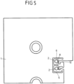
- a nozzle plate 1 of an extrusion device is shown in a front view.
- An extrusion device for the extrusion of plastic profiles has an extrusion nozzle 60 with a flow channel 3 for the plastic melt.
- the extrusion nozzle 60 consists of several nozzle plates 1A, 1B (see Figures 3, 4 ), which are arranged transversely to the direction of flow, which are screwed together so that they do not open as a result of the melt pressure and no plastic melt can escape in the parting planes.
- the flow channel 3 passes through each individual nozzle plate 1A, 1B.
- the flow channel 3 has a single, closed cross section.
- the flow channel 3 can be divided into several branches along the flow path, i.e. within individual nozzle plates 1A, 1B the flow channel 3 has several individual cross sections, which are often defined by so-called spokes (see Fig 6 ) are separated from each other.
- the entire extrusion die 60 is heated to a temperature approximately equal to the melt temperature. This is done via one or more heating zones. Four heating zones are often provided (not shown here for reasons of simplicity), each of which extends over the entire length of the extrusion nozzle 60 and is assigned to the four main directions (up, down, left and right).
- small-scale, locally acting temperature control devices 2 are additionally provided.
- a local temperature control device is assigned to a small section of the flow channel wall, a wall area A, in order to be able to change the temperature locally, so that the flow rate of the melt and thus the wall thickness of the profile can be changed in the effective area.
- the local tempering device 2 is provided within an extrusion die 60 .
- Such a Extrusion nozzle 60 consists of several nozzle plates 1. Extrusion nozzle 60 is all of the metallic parts through which flow channel 3 runs.
- the nozzle plate on the exit side is also often referred to as the exit plate 1A.
- the wall area A to be locally temperature-controlled is arranged in close proximity to the flow channel 3, preferably and usually sufficiently only in the outlet plate 1A or in the second nozzle plate 1B. However, it is entirely possible to form the tempering zone across multiple die plates.
- a nozzle plate 1 of an extrusion nozzle 60 is shown in a front view. This view corresponds to the front view of the extrusion nozzle 60.
- the extrusion direction E points perpendicularly out of the plane of the drawing.
- the associated plastic profile 10 is in cross section 2 shown.
- the plastic profile 10 emerges from the extrusion die 60 .
- constant operating parameters in the flow channel 3 e.g. pressure at the entrance of the extrusion nozzle 60, melt throughput, constant temperature and rheological conditions of the melt at the nozzle entrance, temperature profile in the extrusion nozzle 60, etc.
- a specific local velocity profile of the melt occurs at the exit of the extrusion nozzle 60 .
- extrusion mandrels 7 which are required to form the extrusion gaps, not shown for reasons of clarity. In 6 however, the extrusion mandrels 7 are shown.
- one objective in the design and manufacture of an outlet nozzle plate 1A is to make the mean outlet velocity at the outlet of the extrusion nozzle 60 as constant as possible over the entire outlet gap. Physical and rheological effects more or less oppose this objective, so that the thickness of the exit gap must also be adjusted in order to change the assignable, local wall thickness of the plastic profile 10 and adapt it to the required profile geometry.
- the local velocity profile at the outlet of the extrusion nozzle 60 can be influenced in a targeted manner by the local temperature of the channel wall of the extrusion nozzle 60, the nozzle wall temperature, given essentially unchanged boundary conditions. If the die wall temperature is reduced in a width section of e.g. 10 mm upstream (i.e. viewed from the exit of the extrudate) and the other die wall temperatures are left unchanged, the flow velocity in this width section is reduced. The reduced flow velocity leads to a local reduction in wall thickness - relative to the hardly changed wall thicknesses of all other profile sections.
- a profile section is understood here to mean a section of the plastic profile 10 related to the cross section.
- the single-walled parts 11 at the four corners of the plastic profile 10 are such profile sections (see 2 ).
- This device and this process is particularly advantageous for the profile extrusion of window profiles made of PVC hard, because the flow profile of the plastic melt in the PVC formulations used here is primarily determined by wall sliding, in contrast to other plastics.
- the plastic melt slides directly along the steel wall of the flow channel 3; at best there is a thin sliding layer of deposited lubricants in between.
- the velocity at the wall of the flow channel 3 is not zero.
- Targeted changes in the nozzle wall temperature therefore have a direct effect on the sliding resistance of the plastic melt.
- a lower nozzle wall temperature increases the sliding resistance and thus leads to a lower sliding speed.
- the extrusion nozzles 60 are usually temperature-controlled in such a way that the nozzle body has a temperature which corresponds approximately to the average mass temperature of the plastic melt, i.e. the extrusion nozzle 60 is temperature-controlled to approx. 190° C. (e.g. in the case of PVC). In the case of rigid PVC, a die wall temperature of 190 to 195°C is established in the majority of the die gap.
- the difference in throughput can be compensated for by increasing one nozzle wall temperature and lowering the other nozzle wall temperature by up to 5°C. Since the entire extrusion nozzle 60 is affected by the temperature change, essentially all wall thicknesses of the plastic profile 10 are affected equally.
- the effect of temperature control also depends on whether only one duct wall is affected by the temperature change--if this forms a hollow chamber--or whether both duct walls are affected--if protruding, single-walled profile sections 11 are formed. This also shows the limits for general changes in the nozzle temperature; Single-wall profile sections 11 change the wall thickness about twice as much as hollow chamber profile sections 13, inner walls are hardly affected.
- the die wall temperature is controlled in a targeted manner at least in a wall area A, i.e. a die wall temperature is set which is above or below the average temperature at the extrusion die 60.
- Tempering channels 2 are provided, are passed through the tempering fluids, such as oils, air or other gases.
- electrical heating elements can be used in the spatial vicinity of the profile sections 11, 13 to be tempered.
- thermoelectric elements such as Peltier elements, for example, which are arranged in close proximity to the temperature-controlled wall area of the extrusion nozzle 60, can also be advantageous. It is advantageous here that heating or cooling can be provided directly by adjusting the current flow. There is no thermal treatment of fluids.
- local changing of the die wall temperature is only required over a small length range A compared to the overall length of the extrusion die 60.
- the temperature control is advantageously carried out close to the nozzle outlet area.
- Extrusion nozzles 60 for window profiles have an overall length of approximately 150 to 300 mm.
- the temperature changes caused by the local temperature control device preferably only take place on the outlet side in a length range of up to 100 mm upstream, with the length dimension of the wall area to be temperature controlled itself being about 20 to 80 mm. The further upstream the temperature change occurs, the wider the profile section that is affected by the thickness change, which in many cases is not desirable.
- extrusion dies 60 for window profiles this applies either only to the exit plate 1A (usual thickness of about 15 to 25 mm) and/or the next die plate 1B upstream, ie counting against the direction E of extrusion.
- the usual thicknesses of the nozzle plates 1 are about 20 to 50 mm.
- the use of local temperature control is not only limited to single-walled profile sections 11, but can also be extended to any desired profile sections 13, ie also to hollow chamber areas. With these embodiments, even the thickness of inner walls 13 of profiles can be changed during the ongoing extrusion operation without mechanical rework.
- the direction of flow of the cooling air could also be in the opposite direction, i.e. the air is sucked off at the nozzle housing, with the throttle member being located in the suction line, and the air is sucked in from the front side of the nozzle, possibly also from hollow profile chambers.
- the die plates 1A, 1B have a flow channel 3 which opens out into the outlet of the extrusion die 60 .
- the remaining plates and the mandrel parts 7 are not shown here for reasons of clarity.
- the shaping contour is typical for window profiles (see 2 in cross section):
- the hollow chamber areas of the plastic profile 10 are formed by the channel wall of the nozzle plate 1A, 1B and the mandrel parts 7, not shown in the picture.
- the protruding, single-wall profile sections 11 are represented by the peripheral Flow channels 12 are formed, with each flow channel 3 delimiting the single-walled profile sections 11 on both sides (and also at the end; thus U-shaped) and being formed only by the nozzle plate 1A, 1B itself.
- the temperature control channels 2 here represent an embodiment of a local temperature control device, with alternative embodiments still being described.
- the local temperature control device 2 can have, for example, a plurality of temperature control channels 2, which can all have identical or different temperatures.
- a local temperature control device 2 allows the targeted temperature control of individual wall areas (sections) of the flow channel 3 for a plastic profile 10, e.g. specifically for a single-walled area 12 of the plastic profile 10.
- the local temperature control device 2 does not heat or cool the entire flow channel 3 on the entire circumference, but only certain wall areas A in order to specifically and locally influence the flow of the plastic melt.
- the temperature control channels 2 are spatially arranged and shaped in such a way that they at least partially surround the peripheral flow channels 12 that form the single-walled profile sections 11 in order to enable efficient and targeted temperature control of the peripheral flow channels 12. At least one temperature control channel 2 is thus assigned to each of the peripheral flow channels 12 .
- a temperature control zone forms around the temperature control channels 2 in the wall of the flow channels 3 , 12 .
- In 3 is a sectional view (in 1 characterized by the section AA) represented by the nozzle plate 1.
- the direction of extrusion E is represented by an arrow.
- a temperature control channel 2 is assigned to the peripheral flow channels 12 each at a close spatial distance.
- the supply lines 9 for the tempering channels 2 are shown.
- the temperature control channels 2 are supplied with air in such a way that the air (eg with room temperature as the cooling medium) is conveyed laterally via the supply lines 9 into the nozzle plate 1 .
- the feed lines 9 run parallel to the broad side of the nozzle plate 1. In the area of the peripheral flow channels 12, the feed lines 9 meet the temperature control channels 2, which run parallel to the peripheral flow channels 12 here.
- an inlet opening 4 for the air is arranged in each of the temperature control channels 2 .
- the temperature control channels 2 are each closed by a plug 14 (e.g. made of copper), so that in the event of minor leaks in the parting plane to the adjacent nozzle plate, no plastic melt can penetrate from the flow lines, which could lead to blockage of the temperature control channels 2.
- a plug 14 e.g. made of copper
- Air as the temperature control medium thus emerges at the end face of the nozzle plate 1A.
- the temperature control channels 2 are preferably produced by means of wire erosion and are arranged approximately parallel to the flow channels 12 at a distance of approx. 1 to 3 mm.
- the flow rate of the air in the temperature control channels 2 is adjusted mechanically, e.g. by a tap or another throttle device 30, and leads to a corresponding reduction in temperature of the wall of the temperature control channel 2, which, as a result of heat conduction, affects the wall temperature in the wall area A of the flow channel 12 for the plastic melt affects and changes the flow resistance and thus the local flow rate of the plastic melt.
- the temperature control channels 2 are used with air as the temperature control medium for targeted cooling. If the air is heated before it enters the temperature channels 2, the same arrangement can also be used for targeted heating, which also enables the flow rates of the melt to be set in a targeted manner. In this case, the flow rate is increased.
- thermocontrol medium another gas or liquid such as water can also be used as the temperature control medium.
- temperature control can take place as a function of profile properties.
- the temperature control channels 2 have both a supply line and a discharge line for the temperature control medium, with the supply lines 9 being basically arranged as shown in FIG 1 shown, namely on the side of the second nozzle plate 1B.
- the outgoing lines are arranged parallel to this.
- each temperature control channel 2 In 4 an inlet opening 4 and an outlet opening 5 for the temperature control medium are shown in each temperature control channel 2 .
- the tempering channels 2 are expediently sealed off from the parting planes by plugs 14 .
- temperature control channels 2 can be incorporated both in the first nozzle plate 1A and in the second nozzle plate 1B.
- the tempering medium in the respective tempering channels 2 can have the same temperature.
- the respective tempering media can also be different.
- the temperature control does not have to be done exclusively with a medium such as cooling or heating air. Additionally or alternatively, an electrical thermocouple for heating and/or cooling can also be provided as the local temperature control device 2, which heats or cools the wall of the extrusion die 60 in certain areas, in particular in the flow channels 12.
- thermoelectric heating element 2 for the area-wise temperature control of a die plate 1 as an extrusion device.
- heating cartridges 2 are used in bores provided for this purpose.
- cooling cartridges 2 can be used, in which an electric triggered cooling effect, for example as a result of the Peltier effect, is effected.
- Peltier elements are generally designed as flat components, so that they can be arranged in corresponding pockets in the nozzle plate 1 to save space.
- local temperature control devices 2 which have been described in the previous embodiments, can also be combined with one another.
- a temperature control channel 2 and an electrical thermocouple can be used as local temperature control devices 2 in one and the same nozzle plate 1 .
- the mandrel parts 7 are equipped with webs 8 (in 6 provided with reference numbers only in selection) am Nozzle body attached and have the same longitudinal extent as the nozzle plate 1.
- the webs 8 do not extend to the nozzle outlet, but are set back from the outlet surface by about 5 to 15 mm. In the area of the webs 8, a plurality of spatially separate flow channels for the plastic melt are thus formed. Only after these webs 8 have run out is a single, self-contained flow channel 3 formed, which ultimately forms the plastic profile 10 as a whole.
- the nozzle plate 1 also shows the connection channels 9 for the tempering medium, here again air, which run inside the extrusion device, ie here in the nozzle plate 1 .
- temperature control channels 2 are incorporated, which are spatially in the immediate vicinity of an inner wall 13 to be extruded (see Fig 2 ) lay.
- This inner wall 13 forms (see 2 ) the upper wall of the largest hollow chamber in the extrusion profile 10.
- the sectional view is in the area of the spokes 8 and within the temperature control channel 2 and the inlet and outlet lines 9 of the temperature control medium.
- the outlet-side parts of the flow channel 3 for the plastic profile 10 can also be seen.
- the temperature control channel 2 has a meandering shape (see arrows in 9 ).
- the temperature control channel 2 is closed on all sides.
- the closure at the end faces of the mandrel segment takes place here by pressing in a closure plug 14 made of copper.
- the spokes 8 should preferably be narrow, only a small bore is available here for the inlet and outlet of the tempering medium.
- a high flow rate of the temperature control medium is required, which can easily be generated by a corresponding pressure in the supply line. In the case of air, pressures (overpressure) below 6 bar, mostly those below 1 bar, are sufficient.
- the wall area A in the embodiment according to FIG Figures 7, 8 and 9 is thus an essentially rectangular area through which the temperature control channel 2 runs in a meandering manner.
- the temperature control channels 2 do not have to be arranged in the outlet plate 1, as described in part, but can also be provided in nozzle plates 1B located further upstream. It is expedient here to seal off the temperature control channels 2 at both ends, which means that an additional outlet hole has to be provided. Since preferably only the feed lines 9 are used for controlling the temperature control intensity, several discharge lines can be combined and routed to the outside in a single bore or cutout in the parting plane.
- a section of the plastic profile 10 is shown with wall thicknesses of different thicknesses, where 10 shows the plastic profile 10 with the correct wall thicknesses of all profile sections 11, which arise when all influencing factors, in particular the extruder parameters and the flow parameters, have the correct sizes.
- the plastic profile 10 can be brought into the correct shape using known measures: The withdrawal speed of the plastic profile 10 is increased relative to the throughput of the plastic melt. All wall thicknesses are reduced to the same extent, and the propulsion of the hooks is reduced or eliminated altogether.
- the geometry error can be corrected by using one of the embodiments: Cooling air is used as the temperature control medium through the temperature control channels 2, which are assigned to the overfilled hooks 11 (i.e. a single-walled profile section). blown. By changing the flow properties of the plastic melt in this spatially limited area, only the wall thickness of the hook 11 is reduced. The displacement of the excess plastic melt towards the hollow chamber is prevented, and the vertical wall is given the desired straight shape without the wall thickness being reduced here as well.
- the described embodiments make it possible to set the wall thickness in different profile sections 11, 13 largely independently of one another during the profile extrusion and to optimize them individually.
- the result is dimensionally correct plastic profiles 10, fewer rejects and plastic profiles 10 close to the lower meter weight tolerance because unavoidable wall thickness fluctuations can be specifically compensated for at certain points.
- In 12 is the cross section of the section of the plastic profile 10 from FIG 10 shown, with in the area of the two hooks 11 too little material is available.
- the wall thicknesses are too thin, the surfaces are warped and the edges are not sufficiently pronounced. Functional dimensions are not adhered to.
- the section from the plastic profile 10 is not true to size.
- the wall thickness in the area of the hooks 11 can be increased without increasing all other wall thicknesses: the temperature channels 2 are now used as heating channels.
- the air supplied in the same way as above is preheated to a temperature of approx. 300 to 500°C.
- spatially limited areas in the walls of the flow channels 12 for the plastic melt are heated in a targeted manner.
- This increased temperature of the wall of the flow channels 12 reduces the flow resistance of the plastic melt and the flow rate increases only in those areas in which an increased temperature is effective.
- plastic profiles 10 are again obtained, there are fewer rejects and plastic profiles 10 are close to the lower meter weight tolerance because unavoidable wall thickness fluctuations can be compensated for in a targeted manner at certain points.
- the inlet area of the dry calibration 20 is shown on the left, and the outlet area of the extrusion nozzle 60 with the outlet plate 1 is shown on the right.
- the plastic material moves through the flow channel 3 of the extrusion nozzle 60, then briefly freely in space, and on the left it enters the dry calibration 2.
- the plastic melt strand jumps up by about 20% after leaving the extrusion nozzle 60 (ie the extruded plastic profile 10 widens, as in 13, 14 and 15 is shown schematically), which is compared to the average flow rate in the extrusion die 60 is due to slower withdrawal rate.
- a temperature control channel 2 for locally influencing the wall thickness of the plastic melt strand 10 is shown in the outlet plate 1A.
- air at room temperature is applied to temperature control channel 2; the tempering channel 2 is therefore used for cooling.
- the air throughput through the temperature control channel 2 can be adjusted via a throttle device 30, e.g. a manually operated tap. When the throttle device 30 is closed, no air flows. The wall of the flow channel 3 for the plastic melt strand 10 is not actively cooled. A temperature equilibrium is established in the extrusion nozzle 30 and the local melt throughput in the region shown reaches its maximum.
- the response time is about 2 to 10 seconds, at most about 1 minute, ie the effect of a change in the temperature control can be observed very quickly and the new temperature equilibrium of the extrusion nozzle 60 is established comparatively quickly a. If a suitable setting is found, i.e. the local throughput in the respective segment to the target range introduced, production runs stably over a long period of time as long as no disturbances occur.
- the wall thickness and/or the degree of filling in a specific profile section 11 is the control variable and the input variables of the temperature control device 2, e.g. the position of the throttle valve in the throttle device 30 and/or the temperature of the temperature control medium are the control variables.
- the manipulated variables then act on the temperature of the duct wall and thus on the throughput or the flow rate.
- a temperature control device 2 is shown in which, in the simplest case, the temperature in the flow channel wall, ie the wall area A, can be changed by manually adjusting a throttle device 30 .
- the wall thickness of the plastic profile 10 is visually observed or measured by a suitable measuring device 40 .
- the flow restrictor 30 is adjusted by hand so that the profile section 11 has the desired thickness. Extrusion can then take place over a longer period of time without continuous observation or measurement, i.e. without further adjustment of the flow restrictor.
- an automatic control circuit can be formed.
- the measuring device 40 measures a characteristic dimension (wall thickness, air gap and/or bulge, etc.). If this dimension deviates from the target dimension, the control device 50 causes the flow restrictor to be adjusted. Measurement and adjustment take place continuously and automatically, which is why we speak of a regulation. Alternatively, instead of the throughput of the tempering medium, its temperature can also be adjusted.
- the control variable wall thickness can be recorded in different ways:
- the wall thickness can be measured directly by means of an ultrasonic, optical or laser measurement.
- the distance (air gap) between the plastic profile 10 and the calibrator wall can also be used as a measured variable, for which the measurement methods mentioned can also be used.
- the measurement methods can also be used in combination with one another.
- a differential pressure for example the back pressure when the air gap is subjected to a certain initial pressure, can also be used as a measurement signal that can be generated comparatively easily.
- the measurement signal, the back pressure changes with the gap width (see e.g 14 ), which is available for the outflow of the tempering medium (e.g. air): If the material is directly adjacent to an outlet opening 15 for the measuring air, this is closed and the back pressure reaches its maximum. If the gap becomes larger, the dynamic pressure decreases.
- the tempering medium e.g. air
- a mechanical measurement is also well suited as a measurement variable: a measuring probe rests on the surface of the plastic profile 10 and measures wall thickness fluctuations. - In principle, it is not at all necessary to know the exact numerical values for the wall thickness. In the end, it is only important to maintain a state that is defined as permissible or optimal through the control.
- the measured variable is the back pressure in the inlet-side air gap 17 of the dry calibration 20.
- the wall thickness of the profile section 11 is recorded indirectly. If the gap 17 between the plastic profile 10 and the calibrator wall is subjected to a slight excess pressure (less than 1 bar, usually less than 0.2 bar), a back pressure is created. This back pressure is all the greater, the smaller the gap, ie the greater the wall thickness of the plastic profile 10 is. This back pressure is applied to an actuator which changes the throughput of the tempering medium in the desired direction.
- a slide can be used as an actuator, which influences the flow rate of the tempering medium.
- the extrusion nozzle 60 is adjusted in such a way that in the initial state the target wall thickness is reached when the flow rate through the temperature control channel 2 is partially throttled by the slide. A sufficiently large control margin is thus available.
- An air flow 16 is applied to both the temperature control channel 2 and the outlet opening 15 for the measurement air.
- the desired thickness is set by manually adjusting the throttle device 30, then the control is activated.
- the throttle 30 is adjusted as a result of the pressure or directly by this pressure until the pressure is the same as when the regulation was activated.
- Complex control with a computer is not required.
- the throttle device 30 can be used for this purpose be constructed similar to a servo valve. No electrical signal is required for the control, the adjustment is made by the flowing medium itself.
- the back pressure is used indirectly as a measurement signal, the larger the gap, the smaller the back pressure.
- the profile section 11 in the exit plate 1 of the extrusion nozzle 60 is to be cooled as the wall thickness increases, ie the gap at the measuring point decreases and the back pressure increases. That is, the throughput of the cooling air as a temperature medium must be increased, the actuator must open.
- the actuator must reduce the throughput in response to the decreasing back pressure, i.e. close it.
- the initial position of the actuator can be set manually, e.g. via an adjusting screw which is arranged between the automatic adjustment and the actual actuator, the slide.
- the outlined controlled system can be adjusted with the simplest tools with regard to the response behavior.
- blower Various controlled systems can be acted upon in parallel by a single air supply in the form of a blower. Because a comparatively small blower (motor power 300 W, maximum pressure +0.2 bar (for comparison Household vacuum cleaner: Motor power 1.8 kW, maximum suction pressure -0.2 bar)) is sufficient to be able to control up to 10 segments, whereby even then the entire blower power does not have to flow through the temperature control channels 2, there is no risk of mutual interference or there is no risk of it .only tolerably small.
- motor power 300 W, maximum pressure +0.2 bar for comparison Household vacuum cleaner: Motor power 1.8 kW, maximum suction pressure -0.2 bar
- the back pressure when an air gap 17 is acted upon in the dry calibration 20 is used as the measured variable.
- the measuring point 15 to which the measuring air flow 16 is applied is now approximately in the central area of the first dry calibration 20 (counted in the extrusion direction E).
- the correct shaping of the profile segment 11 can initially be set manually. A certain back pressure then corresponds to this state. If the control is then activated, this back pressure is automatically maintained.
- an actuator in this example a throttle element 30, is acted upon, as a result of which the air throughput through the temperature control channel 2 is changed.
- the flow cross section in the throttle element 30 is increased or decreased until the back pressure is again at the starting level when the control is activated.
- This invention is not limited to window profiles made of PVC or other profiles made of any plastic.
- the wall area, in which the local temperature control takes place extends predominantly in the width and less in the length (i.e. along the extrusion direction E). Also, the temperature control medium does not flow in the direction of extrusion E, but transversely to it, i.e. in the plane of the plate.
- the increase in temperature in the outlet area of the nozzle leads to an increase in the gloss of the surface. It is therefore advantageous to superheat the exit area of the nozzle above the nozzle temperature.
- the wall area of the flow channel A to be temperature-controlled covers the entire width of an outer wall of the plastic profile 10.
- the temperature control channel has a greater extent transversely to the extrusion direction E and a smaller extent in the extrusion direction E.
- a temperature increase in the wall area should not lead to a very significant increase in wall thickness.
- Predominantly only the outermost surface of the melt should be heated, as this also increases the gloss on the surface of the exiting profile, which is desirable for some applications. Conversely, the gloss can also be reduced somewhat by using a lower temperature.
- the temperature control channel 2 for influencing the flow channel wall temperature is only arranged in the nozzle outlet plate 1A and has an extension in the extrusion direction, parallel to the flow channel surface, of at least about 5 mm, and the upper limit is the thickness of the nozzle plate 1A, preferably about 6 to 10mm
- the inlet and outlet 9 for the temperature control medium are preferably in a plane parallel to the plane of the plate, the temperature control medium flows through the temperature control channel essentially transversely to the extrusion direction E.
- a nozzle plate 1 is shown in detail, these being provided with two local temperature control devices 2, as has already been described in connection with the other exemplary embodiments.
- Two inlets 9 for the temperature control medium to the local temperature control devices 2 are shown in the section shown.
- Figure 19A is the cut according to 18 shown in a perspective view.
- Figure 19B an enlarged section Figure 19A shown in the area of the local temperature control device 2 .
- the inlets 9 for the tempering medium have a thermal insulating device 70 which ensures increased heat transfer resistance along the inlet 9 .
- the thermal Insulator 70 on an air gap.
- the bore for the actual inlet 9 is dimensioned somewhat larger, so that a temperature-resistant plastic hose or a metal tube can be arranged in the bore as a fluid line 71 .
- the fluid line 71 has a smaller diameter than the surrounding bore, so that an air gap around the fluid line 71 is formed.
- the temperature control medium flows through the fluid line 71 to the local temperature control device 2 (see in particular Figure 19B ).
- the air gap 70 thermally insulates the fluid line 71 from the environment, i.e. the nozzle plate. This makes the heat exchange between the heat transfer liquid and the nozzle plate more difficult, so that the heat transfer liquid is exposed to fewer temperature losses.
- the local temperature control device 2 At the actual point of action, i.e. the local temperature control device 2, there is a higher temperature gradient than when no insulating device 70 is used. This allows the temperature change on the nozzle wall to be efficiently controlled and regulated.
- the temperature field of the nozzle plate 1 changes. This can take between 5 and 30 minutes, for example, which is relatively long.
- the thermal insulation device 70 better insulates the nozzle plate 1 against thermal influences from the tempering fluid.
- the thermal insulation device 70 is formed by an air gap.
- the thermal insulation device can also be designed differently. It is thus possible to place a temperature-coated plastic tube as a fluid line 71 in a bore of the inlet 9 without an air gap. If the wall is thick enough and/or the plastic material has sufficiently poor thermal conductivity, the air gap is irrelevant.
- thermal insulation means can also be used, e.g. an air gap 70 in which an insulated metal pipe is arranged.
- This embodiment with a thermal isolation device 70 can be used with all other described embodiments.
- Example 1 Extrusion device for the extrusion of plastic profiles (10), in particular a die plate (1), with at least one flow channel (3, 12) for plastic melt, characterized in that at least one wall area (A) of the flow channel (3, 12) with a local temperature control device (2) can be temperature-controlled in a targeted manner to adjust the flow rate of the plastic melt.
- Example 2 Extrusion device according to example 1, characterized in that the at least one wall area (A) of the flow channel (3, 12) is heated up to 30°C above or below the mean temperature of an extrusion die (60).
- Example 3 Example 3
- Extrusion device characterized in that the local temperature control device (2) is arranged in close proximity to at least one wall area (A) of the flow channel (3, 12), in particular in the vicinity of the outlet opening of the extrusion nozzle (60).
- example 4 Extrusion device according to at least one of the preceding examples, characterized in that the at least one wall area (A) to be temperature-controlled is arranged between 0 and 100 mm upstream of the outlet of the extrusion die (60) and/or the at least one wall area (A) has a length dimension of approximately 20 to 80 mm and/or has a width dimension of about 3 to 20 mm.
- Example 5 Example 5
- Extrusion device characterized in that the at least one wall area (A) to be temperature-controlled is arranged in the die outlet plate (1A) immediately upstream of the outlet of the extrusion die (60) and the at least one wall area (A) has one dimension in the direction of extrusion from 5 to 20 mm, preferably 6 to 10 mm, and a dimension transverse to the extrusion direction of about 20 to 150 mm, preferably over the entire width of the associated profile surface.
- Example 6 Extrusion device according to at least one of the preceding examples, characterized in that the local temperature control device (2) has at least one temperature control channel, at least one electrical heating means, in particular an induction or resistance heater and/or at least one thermoelectric element.
- Example 7 Extrusion device according to at least one of the preceding examples, characterized in that the local temperature control device (2) has at least one temperature control channel, at least one electrical heating means, in particular an induction or resistance heater and/or at least one thermoelectric element.
- Extrusion device characterized in that at least one temperature control channel (2) of a Tempering medium, in particular room air, cold and/or heated air, a gas and/or a liquid can flow through, with a liquid flowing through in particular in a closed circuit and a gas flowing through in an open circuit.
- a temperature control channel (2) of a Tempering medium in particular room air, cold and/or heated air
- a gas and/or a liquid can flow through, with a liquid flowing through in particular in a closed circuit and a gas flowing through in an open circuit.
- example 8 Extrusion device according to example 7, characterized in that the cooled tempering medium has a temperature between -50 and 30°C in the case of gas and a temperature between 15 and 180°C in the case of liquid, with in particular only the exit zone of the extrusion die (60th ) is cooled.
- Example 9 Extrusion device according to example 7, characterized in that the heated tempering medium has a temperature of between 250 and 500°C in the case of gas and a temperature of between 200 and 280°C in the case of liquid, with in particular only the exit zone of the extrusion die (60) is heated.
- Example 10. Extrusion device according to at least one of Examples 6 to 9, characterized in that at least one temperature control channel (2) has a width extension corresponding to the width dimension of the associated wall area (A) of the flow channel (3, 12), and/or that the gap height of the at least one temperature control channel (2) between 0.3 to 5 mm, preferably up to 2 mm.
- Example 11 Extrusion device according to at least one of Examples 6 to 9, characterized in that at least one temperature control channel (2) has a width extension corresponding to the width dimension of the associated wall area (A) of the flow channel (3, 12), and/or that the gap height of the at least one temperature control channel (2) between 0.3 to 5 mm, preferably up to 2 mm.
- Extrusion device characterized in that the local temperature control device (2) is thermally insulated from the extrusion die (60), in particular a die plate (1) with an air gap (6) and/or by means of a heat-insulating intermediate layer, so that the surface of the flow channel (3, 12) higher temperature differences become effective.
- Example 12 the local temperature control device (2) is thermally insulated from the extrusion die (60), in particular a die plate (1) with an air gap (6) and/or by means of a heat-insulating intermediate layer, so that the surface of the flow channel (3, 12) higher temperature differences become effective.
- Example 12 Example 12
- Extrusion device characterized by the coupling to a control or regulating device (50) for controlling the local temperature control device (2) for influencing a wall thickness of the plastic profile (10), at least one measured variable being the wall thickness, the gap width in a Calibration device (20), a spatial expansion of the plastic profile (10) after leaving the extrusion nozzle (60) and / or a measured back pressure in the calibration device (20).
- Example 13 Extrusion device according to at least one of the preceding examples, characterized in that the flow rate, the flow rate, the pressure and/or the temperature of the tempering medium, in particular air, can be specifically adjusted before it enters the tempering device (2).
- Extrusion device characterized by a control or regulating device (50) for changing the temperature of the at least one wall area (A) of the flow channel (3, 12) over time, in particular for setting a slow, controlled temperature transition of 5 to 15 K/min.
- Example 15 Extrusion device according to at least one of the preceding examples, characterized by a throttle device (30) for targeted adjustment of the throughput of the tempering medium, wherein the throttle device (30) can be coupled in particular to a control or regulating device.
- Example 16 Extrusion device according to at least one of the preceding examples, characterized by a thermal insulation device (70) for the temperature control medium for at least a partial area in the nozzle plate (1).
- Extrusion device characterized in that the insulating device (70) has an air gap (71) and/or an insulating material.
- Example 18 Extrusion process for plastic profiles (10), with at least one flow channel (3, 12), in particular in a nozzle plate (1), for plastic melt, the plastic melt in at least one flow channel (3, 12) for adjusting the flow rate on at least one wall area (A ) of the flow channel (3, 12) is tempered by a local temperature control device (2).
- Example 19 Extrusion process according to Example 18, characterized in that the at least one Wall area (A) of the flow channel (3, 12) 30 ° C above or below the average temperature of the extrusion die (60) is heated.
- Example 20 Extrusion process for plastic profiles (10), with at least one flow channel (3, 12), in particular in a nozzle plate (1), for plastic melt, the plastic melt in at least one flow channel (3, 12) for adjusting the flow rate on at least one wall area (A ) of the flow channel (3, 12) is tempered by a local temperature
- Extrusion process according to example 18 or 19, characterized in that at least one temperature control channel (2) can be flowed through by a temperature control medium, in particular air at room temperature, cooled and/or heated air, a gas and/or a liquid, the flow through with a liquid in particular in a closed circuit and the gas flows through it in an open circuit.
- a temperature control medium in particular air at room temperature, cooled and/or heated air, a gas and/or a liquid
- Example 21 Extrusion method according to example 20, characterized in that the cooled tempering fluid, in particular gas, has a temperature between -50 and 30°C, in particular room temperature, in particular only the exit zone of the extrusion die (60) being tempered.
- Example 22 Example 22.
- Extrusion method characterized by controlling or regulating the actuation of the local temperature control device (2) for influencing a wall thickness of the plastic profile (10), with at least one measured variable being the wall thickness, the gap width in a calibration device (20), is a spatial expansion of the plastic profile (10) after leaving the extrusion die (60) and/or a measured back pressure in the calibration device (20).
- Example 23 Extrusion process according to at least one of Examples 18 to 22, characterized in that the flow rate, the flow rate, the pressure and/or the temperature of the temperature control medium, in particular air, is set in a targeted manner before it enters the temperature control device (2).
Abstract
Die Erfindung betrifft eine Extrusionsvorrichtung für die Extrusion von Kunststoffprofilen (10) mit mindestens einer abstehenden, einwandigen Profilsektion, nämlich eine Düsenplatte (1) oder mehrere Düsenplatten (1, 1A, 1B), umfassend mindestens einen Kunststoffschmelze-Fließkanal (12) für die abstehende, einwandige Profilsektion (11), wobei mindestens ein Wandbereich (A) des Kunststoffschmelze-Fließkanals (12) für die abstehende einwandige Profilsektion (11) mit einer lokalen Temperiervorrichtung (2) zur Einstellung der Strömungsgeschwindigkeit der Kunststoffschmelze gezielt temperierbar ist. Die Erfindung betrifft ferner ein Extrusionsverfahren.The invention relates to an extrusion device for the extrusion of plastic profiles (10) with at least one protruding, single-walled profile section, namely a nozzle plate (1) or several nozzle plates (1, 1A, 1B), comprising at least one plastic melt flow channel (12) for the protruding , single-walled profile section (11), at least one wall area (A) of the plastic melt flow channel (12) for the protruding single-walled profile section (11) being temperature-controlled in a targeted manner with a local temperature control device (2) for adjusting the flow rate of the plastic melt. The invention also relates to an extrusion process.
Description
Die Erfindung betrifft eine Extrusionsvorrichtung zur Beeinflussung der Wanddicke eines extrudierten Kunststoffprofils und ein Verfahren zur Beeinflussung der Wanddicke eines extrudierten Kunststoffprofils.The invention relates to an extrusion device for influencing the wall thickness of an extruded plastic profile and a method for influencing the wall thickness of an extruded plastic profile.
Kunststoffprofile werden häufig durch Extrudieren erzeugt. In einem Extruder wird eine weitgehend homogene Kunststoffschmelze aufbereitet und auf einen Druck von etwa 200 bis 400 bar und eine Temperatur von etwa 200°C gebracht. Die Kunststoffschmelze wird mit hohem Druck durch eine Extrusionsdüse gepresst. Der Ausgang der Extrusionsdüse weist annähernd die Kontur des gewünschten Kunststoffprofils auf.Plastic profiles are often produced by extrusion. A largely homogeneous plastic melt is processed in an extruder and brought to a pressure of around 200 to 400 bar and a temperature of around 200°C. The plastic melt is pressed through an extrusion nozzle at high pressure. The exit of the extrusion die has approximately the contour of the desired plastic profile.
Nach dem Austritt der Kunststoffschmelze aus der Extrusionsdüse gelangt das extrudierte Kunststoffprofil, z.B. in Form eines Schmelzestranges in eine Kalibrierungsvorrichtung, um in dieser unter Beibehaltung der Profilkontur abgekühlt zu werden. Kalibrierungsvorrichtungen für die Herstellung vergleichsweise komplizierter Kunststoffprofile, wie z.B. Fensterprofile als Hohlprofile, weisen üblicherweise einen Trockenkalibrierungsbereich und einen anschließenden Nasskalibrierungsbereich auf.After the plastic melt emerges from the extrusion nozzle, the extruded plastic profile, e.g. Calibration devices for the production of comparatively complicated plastic profiles, such as window profiles as hollow profiles, usually have a dry calibration area and a subsequent wet calibration area.
Die Wanddicken des Kunststoffprofils werden dabei weitgehend in der Düse festgelegt.The wall thicknesses of the plastic profile are largely determined in the nozzle.
Eine Änderung von Wanddicken in der Kalibrierung ist kaum möglich. Bei Hohlkammerprofilen wird die betreffende Außenwand an die Kalibrierung angesaugt und dann vorwiegend über Wärmeableitung abgekühlt. Auf die Innenseite dieser Außenwand (d.h. im Inneren des Kunststoffprofils) kann kein Einfluss, welcher zu einer Wanddickenänderung führen könnte, ausgeübt werden.A change of wall thicknesses in the calibration is hardly possible. In the case of hollow chamber profiles, the outer wall in question is sucked onto the calibration and then cooled down primarily through heat dissipation. No influence which could lead to a change in wall thickness can be exerted on the inside of this outer wall (ie inside the plastic profile).
Bei vom Kunststoffprofil abstehenden, z.B. einwandigen Profilsektionen, wie z.B. Haken oder Nasen, könnte in der Kalibrierung beidseitig eine Druckkraft ausgeübt werden, welche Material seitlich verdrängen würde und somit zu einer geringeren Wanddicke führen würde. Praktisch ist das aber nur in einem sehr kleinen Umfang möglich, weil eine hierfür erforderliche Klemmkraft unweigerlich zu einer Reibkraft führt, welche von der noch weichen, zähflüssigen Kunststoffmasse nicht übertragen werden kann. Die betroffene Profilsektion würde im zu engen Spalt steckenbleiben und zu einem Abreißen des Profilstranges führen.In the case of e.g. single-walled profile sections protruding from the plastic profile, such as hooks or lugs, a compressive force could be exerted on both sides during calibration, which would displace material laterally and thus lead to a smaller wall thickness. In practice, however, this is only possible to a very small extent, because a clamping force required for this inevitably leads to a frictional force which cannot be transferred by the still soft, viscous plastic mass. The affected profile section would get stuck in the too narrow gap and cause the profile strand to tear off.
Der Spalt bzw. die Kontur in der Kalibrierung muss daher für die Ausformung von einwandigen Bereichen immer größer sein als die betreffende Wanddicke bzw. Kontur des Kunststoffprofils, um zuverlässig ein Hängenbleiben des extrudierten Kunststoffprofils in der Kalibrierung zu vermeiden, auch wenn infolge geringfügiger, unvermeidbarer Schwankungen des Durchsatzes aus dem Extruder entsprechende Wanddickenschwankungen auf das Kunststoffprofil übertragen werden. Es ist daher üblich, den Spalt in der Kalibrierung um 0,1 bis 0,3 mm, insbesondere 0,2 mm größer, auszuführen als es der Wanddicke des Profils entspricht.For the formation of single-walled areas, the gap or the contour in the calibration must therefore always be larger than the relevant wall thickness or contour of the plastic profile in order to reliably prevent the extruded plastic profile from getting caught in the calibration, even if this is the result of minor, unavoidable fluctuations Wall thickness fluctuations corresponding to the throughput from the extruder are transferred to the plastic profile. It is therefore customary to make the gap in the calibration 0.1 to 0.3 mm larger, in particular 0.2 mm, than corresponds to the wall thickness of the profile.
Bei der Herstellung von Extrusionsvorrichtungen ist ein erheblicher Fertigungsaufwand in der Extrusionsdüse erforderlich, um die Wanddicken in allen Profilsektionen des extrudierten Kunststoffprofils sicherstellen zu können. Dieser Aufwand betrifft Änderungen der Spaltweiten in den Fließkanälen der Extrusionsdüse entlang des Fließweges.In the manufacture of extrusion devices, a considerable amount of manufacturing effort is required in the extrusion die in order to be able to ensure the wall thicknesses in all profile sections of the extruded plastic profile. This effort relates to changes in the gap widths in the flow channels of the extrusion die along the flow path.
Die Wanddicken der Kunststoffprofile sind nur so weit reproduzierbar, so lange sich die Extrusionsbedingungen nicht ändern. Die Extrusionsbedingungen betreffen alle Parameter im Extruder (Extrudertyp und -größe, Temperaturverlauf im Zylinder, Drehzahl der Schnecken, Durchsatz u.a.) sowie des Materials (Rezeptur, Mischbedingungen, Feuchtegehalt u.a.).The wall thicknesses of the plastic profiles can only be reproduced as long as the extrusion conditions do not change. The extrusion conditions affect all parameters in the extruder (extruder type and size, temperature profile in the barrel, screw speed, throughput, etc.) and the material (recipe, mixing conditions, moisture content, etc.).
Jede Änderung der genannten Parameter kann eine Änderung von Wanddicken an bestimmten Sektionen des Profils mit sich ziehen, d.h. es wird nicht das gesamte Kunststoffprofil tendenziell dicker oder dünner, sondern die Auswirkungen sind bereichsweise unterschiedlich.Any change in the parameters mentioned can lead to a change in wall thicknesses in certain sections of the profile, i.e. the entire plastic profile does not tend to become thicker or thinner, but the effects are different in different areas.
Eine Forderung aus wirtschaftlicher Sicht ist es, Kunststoffprofile mit möglichst niedrigem Metergewicht zu produzieren und gleichzeitig alle Qualitätserfordernisse (Geometrie, Mindestwanddicken, mechanische Festigkeit, Glanz u.a.) zu erfüllen. Es ist beispielsweise nicht möglich, Außenwände bereichsweise dünner auszuführen, als in einschlägigen Normen festgelegt ist. Es müssen die unvermeidbaren Wechselwirkungen bei der herkömmlichen Extrusion betrachtet werden: Wird ein Profil nahe beim minimalen Metergewicht mit guter Qualität produziert, so bedeutet das, das jede Profilsektion annähernd die untere, erlaubte Wanddicke aufweist.From an economic point of view, one requirement is to produce plastic profiles with the lowest possible weight per meter and at the same time to meet all quality requirements (geometry, minimum wall thicknesses, mechanical strength, gloss, etc.). For example, it is not possible to make external walls thinner in certain areas than specified in the relevant standards. The unavoidable interactions in conventional extrusion must be considered: If a profile is produced close to the minimum weight per meter with good quality, this means that each profile section has approximately the lower, permitted wall thickness.
Wenn auf Grund beliebiger Störgrößen in einer Profilsektion, z.B. an einem Haken, ein Unterschreiten der minimalen Wanddicke auftritt, führt dies meistens auch zu einer weiteren negativen Ausprägung der örtlichen Geometrie (z.B. dem "Hängen" einer Kante oder eine ungenaue Ausprägung der Hinterschneidung des Hakens).If, due to any disturbance in a profile section, e.g. on a hook, the wall thickness falls below the minimum, this usually also leads to a further negative characteristic of the local geometry (e.g. the "hanging" of an edge or an inaccurate characteristic of the undercut of the hook). .
Um diese eine Profilsektion in die richtige Qualität überzuführen, ist es eine gängige Maßnahme, entweder den Durchsatz zu erhöhen oder die Abzugsgeschwindigkeit zu verringern. Jede der beiden Maßnahmen führt zu einer örtlichen Verdickung der Wandstärke in der fraglichen Profilsektion, aber unweigerlich auch zu einer Verdickung aller anderen Profilsektionen. Letztendlich wird zwar ein qualitätsmäßig entsprechendes Kunststoffprofil erzeugt, es wird aber ein höherer Materialeinsatz erforderlich.In order to convert this one profile section into the right quality, a common measure is to either increase the throughput or reduce the take-off speed. Each of the two measures leads to a local thickening of the wall thickness in the profile section in question, but inevitably also to a thickening of all other profile sections. Ultimately, although a plastic profile is produced that corresponds in terms of quality, a higher use of material is required.
Es ist daher die Aufgabe, eine Extrusionsvorrichtung und ein Verfahren zu entwickeln, bei denen die Wanddickenverteilung eines extrudierten Kunststoffprofils effizient und gezielt beeinflusst werden kann.The task is therefore to develop an extrusion device and a method in which the wall thickness distribution of an extruded plastic profile can be influenced efficiently and in a targeted manner.
Die Aufgabe wird durch eine Vorrichtung mit den Merkmalen des Anspruchs 1 gelöst.The object is achieved by a device having the features of
Dabei weist eine Extrusionsvorrichtung für die Extrusion von Kunststoffprofilen einen Fließkanal für Kunststoffschmelze auf. Ein Beispiel für eine solche Extrusionsvorrichtung ist eine Düsenplatte. Mindestens ein Wandbereich des Fließkanals ist mit einer lokalen Temperiervorrichtung zur Einstellung der Strömungsgeschwindigkeit der Kunststoffschmelze gezielt temperierbar.In this case, an extrusion device for the extrusion of plastic profiles has a flow channel for plastic melt. An example of such an extrusion device is a die plate. At least one wall area of the flow channel can be temperature-controlled in a targeted manner with a local temperature-control device for setting the flow rate of the plastic melt.
Da das Fließverhalten der Kunststoffschmelze auf Grund der Temperaturabhängigkeit der Viskosität selbst temperaturabhängig ist, ändert sich die Strömungsgeschwindigkeit lokal in Abhängigkeit von der Temperierung. Durch die lokal gezielte Temperierung an mindestens einem Wandbereich ist es möglich, die Wandstärken der zuordbaren Querschnitte des Kunststoffprofils punktuell, also weitgehend ohne Auswirkungen auf die übrigen Profilsektionen zu beeinflussen. Dies ist insbesondere bei vom Kunststoffprofil abstehenden, einwandigen Profilsektionen der Fall.Since the flow behavior of the plastic melt is temperature-dependent due to the temperature dependence of the viscosity itself, the flow rate changes locally depending on the temperature control. The locally targeted temperature control in at least one wall area makes it possible to selectively influence the wall thicknesses of the assignable cross sections of the plastic profile, ie largely without affecting the other profile sections. This is particularly the case with single-walled profile sections protruding from the plastic profile.
Damit sind die Wanddicken z.B. von einwandigen Profilsektionen wie Haken durch Merkmale in der Extrusionsdüse beeinflussbar, um einerseits ein Steckenbleiben des Kunststoffprofils in der Kalibrierung infolge zu großer Wanddicke zu verhindern und andererseits unzulässige Geometrieabweichungen infolge zu geringer Wanddicke (z.B. unvollständig ausgeformte Kanten) zu vermeiden.This means that the wall thicknesses, e.g. of single-walled profile sections such as hooks, can be influenced by features in the extrusion nozzle in order to prevent the plastic profile from getting stuck in the calibration due to excessive wall thickness and also to avoid impermissible geometric deviations due to insufficient wall thickness (e.g. incompletely formed edges).
Vorteilhaft ist eine Ausführungsform, wenn die Temperatur des mindestens einen Wandbereichs des Fließkanals bis zu 30°C oberhalb oder unterhalb der mittleren Temperatur der Extrusionsdüse liegt. Dieser Temperaturbereich reicht aus, um eine wirksame Veränderung der Strömungsverhältnisse zu bewirken.One embodiment is advantageous if the temperature of the at least one wall region of the flow channel is up to 30° C. above or below the average temperature of the extrusion die. This temperature range is sufficient to bring about an effective change in the flow conditions.
Ferner ist es vorteilhaft, wenn bei einer Ausführungsvariante die lokale Temperiervorrichtung in räumlicher Nähe zum zu temperierenden Wandbereich angeordnet ist, insbesondere auch in der Nähe der Austrittsöffnung der Extrusionsdüse. In diesem Bereich wirkt sich eine gezielte Veränderung der Strömungsgeschwindigkeit besonders effizient aus. Konkret ist es vorteilhaft, wenn bei einem Ausführungsbeispiel der mindestens eine Wandbereich zwischen 0 bis 100 mm stromaufwärts vom Austritt der Extrusionsdüse angeordnet ist und / oder der mindestens eine zu temperierende Wandbereich eine Längendimension von etwa 20 bis 80 mm und / oder eine Breitendimension von etwa 3 bis 20 mm aufweist.Furthermore, it is advantageous if, in one embodiment, the local temperature control device is arranged in close proximity to the wall area to be temperature-controlled, in particular also in the vicinity of the outlet opening of the extrusion die. A targeted change in the flow velocity has a particularly efficient effect in this area. In concrete terms, it is advantageous if, in one embodiment, the at least one wall area is located between 0 and 100 mm upstream of the outlet of the extrusion die and/or the at least one wall area to be temperature-controlled has a length dimension of around 20 to 80 mm and/or a width dimension of around 3 up to 20 mm.
In einer weiteren Ausführungsform ist der mindestens eine zu temperierende Wandbereich in der Düsenaustrittsplatte unmittelbar stromaufwärts vom Austritt der Extrusionsdüse angeordnet, wobei der mindestens eine Wandbereich eine Dimension in Extrusionsrichtung von 5 bis 20 mm, bevorzugt 6 bis 10 mm, und eine Dimension quer zur Extrusionsrichtung von etwa 20 bis 150 mm, bevorzugt über die gesamte Breite der zugeordneten Profilfläche, aufweist. Bei dieser Ausführungsform erstreckt sich die Temperiervorrichtung nicht sehr weit in die Extrusionsdüse hinein, sondern ist bewusst nur in einem schmalen Bereich am Austritt angeordnet. Dabei kann es aber sinnvoll sein, um z.B. den Glanz zu verstärken, dass die Temperiervorrichtung sich über einen größeren Bereich des Extrusionsprofils erstreckt.In a further embodiment, the at least one wall area to be temperature-controlled is arranged in the die outlet plate immediately upstream of the outlet of the extrusion die, with the at least one wall area having a dimension in the extrusion direction of 5 to 20 mm, preferably 6 to 10 mm, and a dimension transverse to the extrusion direction of about 20 to 150 mm, preferably over the entire width of the associated profile surface. In this embodiment, the temperature control device does not extend very far into the extrusion nozzle, but is deliberately only arranged in a narrow area at the outlet. However, it can be useful, e.g. to increase the gloss, for the tempering device to extend over a larger area of the extrusion profile.
Die lokale Temperiervorrichtung muss nicht immer ein einziges Teil sein, sondern es kann bei Ausführungsformen auch vorteilhaft sein, wenn die lokale Temperiervorrichtung mindestens einen Temperierkanal, mindestens ein elektrisches Heizmittel, insbesondere eine Induktions- oder Widerstandsheizung und / oder mindestens ein thermoelektrisches Element aufweist. Damit sind auch Kombinationen von Temperierelementen möglich, die zusammen die lokale Temperiervorrichtung bilden. So ist es durchaus möglich, einen Teil der lokalen Temperiervorrichtung nur für die Kühlung, und einen anderen für die Heizung zu verwenden. Auch ist es möglich, die gleiche Baugruppe (z.B. Temperierkanäle) zu unterschiedlichen Zeiten für die Heizung und / oder zur Kühlung zu verwenden.The local temperature control device does not always have to be a single part, but it can also be in embodiments be advantageous if the local temperature control device has at least one temperature control channel, at least one electrical heating means, in particular an induction or resistance heater and/or at least one thermoelectric element. Combinations of temperature control elements are thus also possible, which together form the local temperature control device. So it is quite possible to use part of the local temperature control device only for cooling and another part for heating. It is also possible to use the same assembly (eg temperature control channels) at different times for heating and/or cooling.
Dabei ist es bei einer Ausführungsform vorteilhaft, wenn ein Temperierkanal von einem Temperiermedium, insbesondere Raumluft, kalter und / oder erhitzter Luft, einem Gas und / oder einer Flüssigkeit durchströmbar ist, wobei die Durchströmung mit einer Flüssigkeit insbesondere in einem geschlossenen Kreislauf und die Durchströmung mit einem Gas in einem offenen Kreislauf erfolgt. Bei der Verwendung von Luft, z.B. Raumluft zur Kühlung ist die Arbeit in einem offenen Kreislauf besonders vorteilhaft, da die Luft einfach wieder in den Raum geblasen werden kann. Dabei sind die Temperatur und/oder die Strömungsgeschwindigkeit, zusammengefasst dessen Temperierwirkung der Vorrichtung, veränderbar, entweder getrennt für jeden einzelnen Temperierkanal oder gemeinsam für alle Temperierkanäle oder gemeinsam für Gruppen von Temperierkanälen.It is advantageous in one embodiment if a temperature control medium, in particular room air, cold and/or heated air, a gas and/or a liquid can flow through a temperature control channel, with the flow through with a liquid in particular in a closed circuit and the flow through with a gas in an open circuit. When using air, e.g. room air for cooling, working in an open circuit is particularly advantageous because the air can simply be blown back into the room. The temperature and/or the flow rate, summarizing its temperature control effect of the device, can be changed, either separately for each individual temperature control channel or together for all temperature control channels or together for groups of temperature control channels.
Für eine Kühlung liegt eine vorteilhafte Ausführungsvariante vor, wenn das gekühlte Temperiermedium, insbesondere für den Fall von Gas eine Temperatur zwischen -50 bis 30°C aufweist und für den Fall von Flüssigkeit eine Temperatur zwischen 15 und 180 °C aufweist, wobei insbesondere nur die Austrittszone der Extrusionsdüse gekühlt wird.For cooling, there is an advantageous variant if the cooled tempering medium, in particular in the case of gas, has a temperature between -50 and 30° C. and in the case of liquid, a temperature between 15 and 180° C., with in particular only the Exit zone of the extrusion die is cooled.
Für eine Erhitzung liegt eine vorteilhafte Ausführungsvariante vor, wenn das erwärmte Temperiermedium, insbesondere für den Fall von Gas eine Temperatur zwischen 250 bis 500°C aufweist und für den Fall von Flüssigkeit eine Temperatur zwischen 200 und 280 °C aufweist, wobei insbesondere nur die Austrittszone der Extrusionsdüse geheizt wird.An advantageous embodiment variant for heating is when the heated tempering medium has a temperature of between 250 and 500° C., in particular in the case of gas, and has a temperature of between 200 and 280° C. in the case of liquid, with in particular only the outlet zone of the extrusion nozzle is heated.
Es ist vorteilhaft, wenn eine Ausführungsform mindestens einen Temperierkanal mit einer Breitenerstreckung entsprechend der Breitendimension des zugeordneten zu temperierenden Wandbereichs des Fließkanals aufweist und / oder die Spalthöhe mindestens eines Temperierkanals zwischen etwa 0,3 bis 5 mm, bevorzugt bis 2 mm, liegt. Diese Abmessungen sind geeignet, einen effizienten Wärmeübergang vom Temperierkanal zur Kunststoffschmelze sicherzustellen.It is advantageous if an embodiment has at least one temperature control channel with a width extension corresponding to the width dimension of the assigned wall area of the flow channel to be temperature controlled and/or the gap height of at least one temperature control channel is between about 0.3 to 5 mm, preferably up to 2 mm. These dimensions are suitable for ensuring efficient heat transfer from the temperature control channel to the plastic melt.
Ferner ist es vorteilhaft, wenn die lokale Temperiervorrichtung einer Ausführungsform gegenüber der Extrusionsvorrichtung, insbesondere der Extrusionsdüse, insbesondere einer Düsenplatte mit einem Luftspalt und / oder mittels einer wärmedämmenden Zwischenlage wärmetechnisch isoliert sind, so dass an der Oberfläche des Fließkanals höhere Temperaturdifferenzen wirksam werden.It is also advantageous if the local temperature control device of one embodiment is thermally insulated from the extrusion device, in particular the extrusion die, in particular a die plate with an air gap and/or by means of a heat-insulating intermediate layer, so that higher temperature differences become effective on the surface of the flow channel.
Besonders vorteilhaft ist eine Ausführungsformen, wenn eine Koppelung einer Steuer- oder Regelvorrichtung zur Ansteuerung der lokalen Temperiervorrichtung zur Beeinflussung einer Wanddicke des Kunststoffprofils besteht, wobei mindestens eine Messgröße die Wanddicke, die Spaltbreite eines Luftspaltes in einer Kalibrierungsvorrichtung, eine räumliche Ausdehnung des Kunststoffprofils nach dem Verlassen der Extrusionsdüse und / oder ein gemessener Rückstaudruck in der Kalibrierungsvorrichtung ist.One embodiment is particularly advantageous if there is a coupling of a control or regulating device for controlling the local temperature control device for influencing a wall thickness of the plastic profile, with at least one measured variable being the wall thickness, the gap width of an air gap in a calibration device, a spatial expansion of the plastic profile after leaving of the extrusion nozzle and/or a measured back pressure in the calibration device.
Vorteilhafterweise ist bei einer Ausführungsform die Strömungsgeschwindigkeit, die Durchflussmenge, der Druck und / oder die Temperatur des Temperiermediums, insbesondere Luft, vor dem Einlauf in die Temperiervorrichtung gezielt einstellbar. Eine Aufheizung oder Kühlung des Temperiermediums kann vor dem Eintritt in die Düse effizient erfolgen.Advantageously, in one embodiment, the flow rate, flow rate, pressure, and / or the temperature of the tempering medium, in particular air, can be specifically adjusted before it enters the tempering device. The temperature control medium can be efficiently heated or cooled before it enters the nozzle.
Dabei ist es vorteilhaft, wenn bei einer Ausführungsform eine Steuer- oder Regelungsvorrichtung eine zeitliche Veränderung der Temperierung des mindestens einen Wandbereichs gezielt vornehmen kann, insbesondere zur Einstellung eines kontrolliert langsamen Temperaturübergangs (5 bis 15 K / min) .It is advantageous if, in one embodiment, a control or regulation device can change the temperature of the at least one wall area in a targeted manner over time, in particular to set a slow, controlled temperature transition (5 to 15 K/min).
Zusätzlich oder alternativ kann bei Ausführungsvarianten auch die Temperatur des Temperiermediums dadurch geändert werden, dass die Strömungsgeschwindigkeit des Temperiermediums in der lokalen Temperiervorrichtung (z.B. einem Heiz- oder Kühlkanal) verändert wird, indem eine Drosselvorrichtung zum Zulauf vorgesehen ist, wobei die Drosselvorrichtung insbesondere mit einer Steuer- oder Regelvorrichtung koppelbar ist.In addition or as an alternative, the temperature of the temperature control medium can also be changed in design variants by changing the flow rate of the temperature control medium in the local temperature control device (e.g. a heating or cooling channel) by providing a throttling device for the inlet, the throttling device being equipped in particular with a control - Or control device can be coupled.
Ferner liegt eine vorteilhafte Ausführungsform vor, wenn eine thermische Isoliervorrichtung für das Temperiermedium für mindestens einen Teilbereich in der Düsenplatte vorgesehen ist. Durch die Isoliervorrichtung wird verhindert, dass sich die Temperatur des Temperiermediums insbesondere innerhalb der Düsenplatte ändert, indem z.B. ein Temperaturverlust durch Wärmeleitung eintritt. Dabei ist es besonders vorteilhaft, wenn die Isoliervorrichtung einen Luftspalt und / oder ein Isoliermaterial aufweist.Furthermore, there is an advantageous embodiment when a thermal insulation device for the tempering medium is provided for at least a partial area in the nozzle plate. The insulating device prevents the temperature of the tempering medium from changing, in particular within the nozzle plate, by e.g. a temperature loss occurring as a result of heat conduction. It is particularly advantageous if the insulating device has an air gap and/or an insulating material.
Die Aufgabe wird auch durch ein Extrusionsverfahren mit den Merkmalen des Anspruchs 18 gelöst.The object is also achieved by an extrusion process with the features of
Dabei liegt ein Fließkanal für eine Kunststoffschmelze vor, insbesondere in einer Düsenplatte vor, wobei die Strömungsgeschwindigkeit der Kunststoffschmelze in diesem Fließkanal durch Ändern der Temperatur in mindestens einem Wandbereich des Fließkanals mit einer lokalen Temperiervorrichtung im räumlichen Bereich des Wandbereichs verändert wird. Eine Änderung der Temperatur des mindestens einen Wandbereichs bewirkt eine Änderung des Strömungswiderstandes und dadurch der Strömungsgeschwindigkeit der Kunststoffschmelze.There is a flow channel for a plastic melt, in particular in a nozzle plate Flow rate of the plastic melt is changed in this flow channel by changing the temperature in at least one wall area of the flow channel with a local temperature control device in the spatial area of the wall area. A change in the temperature of the at least one wall area causes a change in the flow resistance and thus in the flow rate of the plastic melt.
Dabei ist es vorteilhaft, wenn bei einer Ausführungsvariante des mindestens einen Fließkanals 30°C oberhalb oder unterhalb der mittleren Düsentemperatur temperiert wird.It is advantageous if, in one embodiment, the at least one flow channel is heated 30° C. above or below the mean nozzle temperature.
Auch liegt eine vorteilhafte Ausführungsform vor, wenn mindestens ein Temperierkanal von einem Temperiermedium, insbesondere Luft bei Raumtemperatur, gekühlter und / oder erhitzter Luft, einem Gas und / oder einer Flüssigkeit durchströmbar wird, wobei die Durchströmung mit einer Flüssigkeit insbesondere in einem geschlossenen Kreislauf und die Durchströmung mit einem Gas in einem offenen Kreislauf erfolgt. Das gekühlte Temperierfluid, insbesondere Gas, liegt bei Ausführungsvarianten vorteilhafterweise in einem Temperaturbereich zwischen -50 bis 30°C, insbesondere bei Raumtemperatur, wobei insbesondere nur die Austrittszone der Extrusionsdüse temperiert wird. Für die Heizung kann Luft mit einer Temperatur zwischen 200 und 500°C verwendet werden.There is also an advantageous embodiment if a temperature control medium, in particular air at room temperature, cooled and/or heated air, a gas and/or a liquid can flow through at least one temperature control channel, with the flow through with a liquid in particular in a closed circuit and the Flow through with a gas takes place in an open circuit. The cooled tempering fluid, in particular gas, is advantageously in a temperature range between −50 to 30° C., in particular at room temperature, in the case of variant embodiments, with only the exit zone of the extrusion nozzle being tempered in particular. Air with a temperature between 200 and 500°C can be used for heating.
Ferner stellt ein Verfahren eine vorteilhafte Ausführungsform dar, bei dem eine Steuerung oder Regelung eine Ansteuerung der lokalen Temperiervorrichtung zur Beeinflussung einer Wanddicke des Kunststoffprofils bewirkt, wobei mindestens eine Messgröße die Wanddicke, die Spaltbreite des Luftspaltes in einer Kalibrierungsvorrichtung, eine räumliche Ausdehnung des Kunststoffprofils nach dem Verlassen der Extrusionsdüse und / oder ein gemessener Rückstaudruck in der Kalibrierungsvorrichtung ist. Dabei liegt eine vorteilhafte Ausführungsvariante vor, wenn die Strömungsgeschwindigkeit, die Durchflussmenge, der Druck und / oder die Temperatur des Temperiermediums, insbesondere Luft, vor dem Einlauf gezielt eingestellt wird.Furthermore, a method represents an advantageous embodiment in which a control or regulation causes activation of the local temperature control device to influence a wall thickness of the plastic profile, with at least one measured variable being the wall thickness, the gap width of the air gap in a calibration device, a spatial expansion of the plastic profile after the leaving the extrusion die and/or a measured back pressure in the calibration device. There is an advantageous variant if the flow rate, the flow rate, the pressure and/or the temperature of the tempering medium, in particular air, is specifically adjusted before the inlet.
Die Erfindung wird anhand verschiedener Ausführungsbeispiele erläutert. Dabei zeigen
-
Fig. 1 eine Vorderansicht der Austrittsplatte eines Extrusionswerkzeugs; -
Fig. 2 eine Schnittansicht eines extrudierten Kunststoffprofils passend zur Extrusionsdüse inFig. 1 ; -
Fig. 3 eine Schnittansicht A-A ausFig. 1 für eine erste Ausführungsform; -
Fig. 4 eine Schnittansicht durch ein Extrusionswerkzeug mit einer zweiten Ausführungsform für eine Temperierung; -
Fig. 5 eine schematische Vorderansicht einer dritten Ausführungsform für eine Temperierung; -
Fig. 6 eine schematische Vorderansicht einer vierten Ausführungsform für eine Temperierung; -
Fig. 7 eine Detailansicht der vierten Ausführungsform gemäßFig. 6 ; -
Fig. 8 eine perspektivische Darstellung der Ansicht ausFig. 7 ; -
Fig. 9 eine Draufsicht auf die Schnittebene derFig. 8 : -
Fig. 10 : eine Querschnittansicht eines Ausschnitts eines Kunststoffprofils mit korrekter Ausformung der Profilsektionen; -
Fig. 11 : eine Querschnittansicht eines Ausschnitts eines Kunststoffprofils mit teilweise überfüllten Profilsektionen; -
Fig. 12 : eine Querschnittansicht eines Ausschnitts eines Kunststoffprofils mit einer Profilsektion, die nur unzureichend aufgefüllt ist; -
Fig. 13 : eine schematische Darstellung einer Temperatursteuerung mit einer Erweiterung für eine Temperaturregelung; -
Fig. 14 : eine schematische Darstellung einer weiteren Ausführungsform einer Temperaturregelung; -
Fig. 15 : eine schematische Darstellung einer dritten Ausführungsform einer Temperaturregelung; -
Fig. 16 : eine Vorderansicht einer weitere Ausführungsform einer Austrittsplatte, mit einer lokalen Temperiervorrichtung; -
Fig. 17 : eine Seitenansicht der Ausführungsform gemäßFig. 16 ; -
Fig. 18 : eine Schnittansicht einer Ausführungsform mit einer thermischen Isolierung eines Zulaufs/Ablaufs für Temperiermedium; -
Fig. 19A : eine perspektivische Ansicht des Schnittes gemäßFig. 18 ; -
FIg. 19B : eine vergrößerte Ansicht aus dem Schnit gemäßFig. 19A .
-
1 a front view of the exit plate of an extrusion die; -
2 a sectional view of an extruded plastic profile matching the extrusion nozzle in1 ; -
3 asectional view AA 1 for a first embodiment; -
4 a sectional view through an extrusion tool with a second embodiment for a temperature control; -
figure 5 a schematic front view of a third embodiment for a temperature control; -
6 a schematic front view of a fourth embodiment for a temperature control; -
7 according to a detailed view of thefourth embodiment 6 ; -
8 a perspective view of theview 7 ; -
9 a plan view of the cutting plane of the8 : -
10 : a cross-sectional view of a section of a plastic profile with correct shaping of the profile sections; -
11 : a cross-sectional view of a section of a plastic profile with partially overfilled profile sections; -
12 : a cross-sectional view of a section of a plastic profile with a profile section that is insufficiently filled; -
13 : a schematic representation of a temperature control with an extension for a temperature regulation; -
14 : a schematic representation of a further embodiment of a temperature control; -
15 1: a schematic representation of a third embodiment of a temperature control; -
16 1: a front view of a further embodiment of an outlet plate, with a local temperature control device; -
17 : a side view of the embodiment according to FIG16 ; -
18 1: a sectional view of an embodiment with thermal insulation of an inlet/outlet for temperature control medium; -
Figure 19A : a perspective view of the section according to FIG18 ; -
FIG. 19B : an enlarged view according to the sectionFigure 19A .
In
Dabei weist eine Extrusionsvorrichtung für die Extrusion von Kunststoffprofilen eine Extrusionsdüse 60 mit einem Fließkanal 3 für die Kunststoffschmelze auf. Die Extrusionsdüse 60 besteht aus mehreren Düsenplatten 1A, 1B (siehe
Der Fließkanal 3 durchsetzt jede einzelne Düsenplatte 1A, 1B. Am Eintritt in die Extrusionsdüse 60 und am Austritt der Schmelze aus der Extrusionsdüse 60 weist der Fließkanal 3 einen einzigen, geschlossenen Querschnitt auf. Entlang des Fließweges kann der Fließkanal 3 in mehrere Äste unterteilt sein, das heißt innerhalb einzelner Düsenplatten 1A, 1B weist der Fließkanal 3 mehrere Einzelquerschnitte auf, welche häufig durch sogenannte Speichen (siehe
Im Sinne dieser Erfindung werden zusätzlich kleinräumige, lokal wirkende Temperiervorrichtungen 2 vorgesehen. Eine derartige, lokale Temperiervorrichtung ist einem kleinen Ausschnitt der Fließkanalwandung, einem Wandbereich A zugeordnet, um die Temperatur lokal verändern zu können, so dass in der Folge die Strömungsgeschwindigkeit der Schmelze und damit die Wanddicke des Profils im Wirkbereich verändert werden kann.Within the meaning of this invention, small-scale, locally acting
Die lokale Temperiervorrichtung 2 gemäß dieser Erfindung wird innerhalb einer Extrusionsdüse 60 vorgesehen. Eine derartige Extrusionsdüse 60 besteht aus mehreren Düsenplatten 1. Die Extrusionsdüse 60 ist dabei die Gesamtheit der metallischen Teile, die vom Fließkanal 3 durchzogen werden.The
Die austrittseitige Düsenplatte wird häufig auch als Austrittsplatte 1A bezeichnet. Wie im Folgenden noch erläutert wird, wird der lokal zu temperierende Wandbereich A in enger Nähe zum Fließkanal 3 angeordnet, bevorzugt und meistens ausreichend nur in der Austrittsplatte 1A oder in der zweiten Düsenplatte 1B. Es ist aber durchaus möglich, die Temperierzone plattenübergreifend über mehrere Düsenplatten auszubilden.The nozzle plate on the exit side is also often referred to as the
In
Die Extrusionsrichtung E zeigt senkrecht aus der Zeichnungsebene heraus. Das dazugehörige Kunststoffprofil 10 ist im Querschnitt in
Das Kunststoffprofil 10 tritt aus der Extrusionsdüse 60 aus. Bei konstanten Betriebsparametern im Fließkanal 3 (z.B. Druck am Eintritt der Extrusionsdüse 60, Schmelzedurchsatz, gleichbleibende Temperatur- und rheologische Verhältnisse der Schmelze am Düseneintritt, Temperaturverlauf in der Extrusionsdüse 60 u.a.) stellt sich ein bestimmtes, örtliches Geschwindigkeitsprofil der Schmelze am Austritt der Extrusionsdüse 60 ein.The
In
An jedem Breitenabschnitt des Austrittsspaltes ergibt sich eine mittlere Geschwindigkeit, welche über die betreffende Querschnittsfläche den dem jeweiligen Breitenabschnitt zuordenbaren Durchsatz ergibt. Die Wanddicke in diesem Breitenabschnitt des Kunststoffprofils 10 (siehe
Grundsätzlich ist es eine Zielsetzung bei der Konstruktion und Fertigung einer Austrittsdüsenplatte 1A, die mittlere Austrittsgeschwindigkeit am Austritt der Extrusionsdüse 60 möglichst konstant über dem gesamten Austrittsspalt zu gestalten. Physikalische und rheologische Effekte stehen dieser Zielsetzung mehr oder weniger entgegen, so dass zusätzlich die Dicke des Austrittsspaltes angepasst werden muss, um die zuordenbare, örtliche Wanddicke des Kunststoffprofils 10 zu verändern und an die geforderte Profilgeometrie anzupassen.In principle, one objective in the design and manufacture of an
Es hat sich jetzt gezeigt, dass das örtliche Geschwindigkeitsprofil am Austritt der Extrusionsdüse 60 bei im Wesentlichen unveränderten Randbedingungen durch die örtliche Temperatur der Kanalwand der Extrusionsdüse 60, der Düsenwandtemperatur, gezielt beeinflusst werden kann. Vermindert man in einem Breitenabschnitt von z.B. 10 mm stromaufwärts (d.h. vom Austritt des Extrudats betrachtet) die Düsenwandtemperatur und lässt die übrigen Düsenwandtemperaturen unverändert, so vermindert sich in diesem Breitenabschnitt die Strömungsgeschwindigkeit. Die verminderte Strömungsgeschwindigkeit führt zu einer örtlichen Verminderung der Wanddicke - relativ zu den kaum veränderten Wanddicken aller anderen Profilsektionen.It has now been shown that the local velocity profile at the outlet of the
Unter einer Profilsektion wird hier ein auf den Querschnitt bezogener Ausschnitt des Kunststoffprofils 10 verstanden. Die einwandigen Teile 11 an den vier Ecken des Kunststoffprofils 10 sind solche Profilsektionen (siehe
Änderungen der Düsenwandtemperaturen (d.h. Temperaturen in Wandbereichen A in der Extrusionsdüse 60) in ausgewählten Profil- bzw. Düsensektionen von etwa +/- 30°C von der mittleren Temperatur an der Extrusionsdüse 60 sind zulässig, ohne dass dies störende Auswirkungen auf andere Qualitätsparameter des Kunststoffprofils 10 hat. Die Einstellung der Extremwerte dieses Temperaturbereiches führt zu Änderungen der mittleren Strömungsgeschwindigkeit von etwa +/-15 %, was die Möglichkeit eröffnet, nahezu alle zufällig auftretenden Wanddickenabweichungen infolge unvermeidbarer Störgrößen auf die Sollwanddicke zurückzuführen.Changes in die wall temperatures (i.e. temperatures in wall areas A in the extrusion die 60) in selected profile or die sections of about +/- 30°C from the average temperature at the extrusion die 60 are permissible without this having a disruptive effect on other quality parameters of the
Gerade bei der Profilextrusion von Fensterprofilen aus PVC-hart ist diese Vorrichtung und dieses Verfahren vorteilhaft, weil das Strömungsprofil der Kunststoffschmelze bei den hierbei eingesetzten PVC-Rezepturen im Gegensatz zu anderen Kunststoffen vorwiegend durch das Wandgleiten bestimmt wird.This device and this process is particularly advantageous for the profile extrusion of window profiles made of PVC hard, because the flow profile of the plastic melt in the PVC formulations used here is primarily determined by wall sliding, in contrast to other plastics.
Die Kunststoffschmelze gleitet unmittelbar an der Stahlwand des Fließkanals 3 entlang; allenfalls befindet sich eine dünne Gleitschicht aus abgelagerten Gleitmitteln dazwischen. Die Geschwindigkeit an der Wand des Fließkanals 3 ist nicht Null.The plastic melt slides directly along the steel wall of the
Gezielte Änderungen der Düsenwandtemperatur wirken sich daher unmittelbar auf den Gleitwiderstand der Kunststoffschmelze aus. Eine tiefere Düsenwandtemperatur erhöht den Gleitwiderstand und führt dadurch zu einer geringeren Gleitgeschwindigkeit.Targeted changes in the nozzle wall temperature therefore have a direct effect on the sliding resistance of the plastic melt. A lower nozzle wall temperature increases the sliding resistance and thus leads to a lower sliding speed.
Fast alle anderen Kunststoffschmelzen außer PVC werden durch das Scherfließen dominiert, wobei die Schmelze an der Stahlwand haftet. Hierbei ist die Geschwindigkeit an der Wand des Fließkanals 3 Null und in der Mittelebene am größten; der Verlauf entspricht etwa einer Parabel höherer Ordnung. Bei derartigen Schmelzen wirkt sich eine gezielte Änderung der Düsenwandtemperatur weniger auf die Strömungsgeschwindigkeit bzw. die mittlere Strömungsgeschwindigkeit aus, weil weitgehend unabhängig von der Temperatur der Stahlwand hier ohnehin keine Strömungsgeschwindigkeit vorliegt.Almost all plastic melts other than PVC are dominated by shear flow, with the melt sticking to the steel wall. Here, the speed on the wall of the
Bei einem Absenken der Düsenwandtemperatur werden infolge Wärmeleitung erst allmählich tiefere Schichten der Schmelze abgekühlt und dadurch kleinere Schergeschwindigkeiten und in der Folge kleinere Strömungsgeschwindigkeiten bewirkt. Eine Änderung der Düsenwandtemperaturen im selben Ausmaß wie oben angeführt, also +/- 30°C, wirkt sich weniger deutlich aus, und führt zu Änderungen der mittleren Strömungsgeschwindigkeit von etwa +/- 7%.When the temperature of the nozzle wall drops, lower layers of the melt are only gradually cooled as a result of heat conduction, causing lower shear rates and consequently lower flow rates. A change in nozzle wall temperatures of the same magnitude as above, ie +/- 30°C, has less of an effect, and leads to changes in mean flow velocity of about +/- 7%.
Dennoch können die im Folgenden beschriebenen Ausführungsformen auch bei anderen Kunststoffen als PVC-hart verwendet werden.Nevertheless, the embodiments described below can also be used with plastics other than rigid PVC.
Üblicherweise sind die Extrusionsdüsen 60 so temperiert, dass der Düsenkörper eine Temperatur aufweist, welche etwa der mittleren Massetemperatur der Kunststoffschmelze entspricht, d.h. die Extrusionsdüse 60 ist auf ca. 190°C temperiert (z.B. für den Fall von PVC). Im Falle von PVC-hart stellt sich eine Düsenwandtemperatur im überwiegenden Teil des Düsenspaltes von 190 bis 195°C ein.The extrusion nozzles 60 are usually temperature-controlled in such a way that the nozzle body has a temperature which corresponds approximately to the average mass temperature of the plastic melt, i.e. the
Werden im Falle einer Doppelextrusion zwei gleichartige Extrusionsdüsen 60 parallel beaufschlagt, so ist zu erwarten, dass durch beide Düsen der gleiche Massestrom, jeweils die Hälfte des Gesamt-Massestromes, fließt. Dies trifft im Großen und Ganzen zu, aber Unterschiede bis zu 10% können durchaus auftreten, weil der Durchsatz sehr empfindlich auf geringfügige, geometrische Unterschiede infolge unvermeidbarer Fertigungsfehler sowie auf geringfügige Unterschiede im Temperaturfeld der beiden Masseströme reagiert.If, in the case of a double extrusion, two
Durch Erhöhen der einen Düsenwandtemperatur und Absenken der anderen Düsenwandtemperatur um jeweils bis zu 5°C kann der Durchsatz-Unterschied ausgeglichen werden. Da von der Temperaturänderung jeweils die gesamte Extrusionsdüse 60 betroffen ist, sind im Wesentlichen alle Wanddicken des Kunststoffprofils 10 gleichermaßen betroffen.The difference in throughput can be compensated for by increasing one nozzle wall temperature and lowering the other nozzle wall temperature by up to 5°C. Since the
Allerdings ist im Falle von komplexen Hohlkammerprofilen (siehe
Ferner hängt die Wirkung der Temperierung auch davon ab, ob von der Temperaturänderung nur eine Kanalwandung betroffen ist - wenn diese eine Hohlkammer ausbildet -, oder ob beide Kanalwandungen betroffen sind - wenn abstehende, einwandige Profilsektionen 11 ausgebildet werden. Dadurch sind auch die Grenzen bei allgemeiner Änderung der Düsentemperatur aufgezeigt; einwandige Profilsektionen 11 verändern die Wanddicken etwa doppelt so stark wie Hohlkammer-Profilsektionen 13, Innenwände werden kaum beeinflusst.Furthermore, the effect of temperature control also depends on whether only one duct wall is affected by the temperature change--if this forms a hollow chamber--or whether both duct walls are affected--if protruding, single-
Im Rahmen der hier beschriebenen Vorrichtung und dem beschriebenen Verfahren wird die Düsenwandtemperatur mindestens in einem Wandbereich A gezielt temperiert, d.h. es wird eine Düsenwandtemperatur eingestellt, die ober- oder unterhalb der mittleren Temperatur an der Extrusionsdüse 60 liegt.Within the scope of the device and the method described here, the die wall temperature is controlled in a targeted manner at least in a wall area A, i.e. a die wall temperature is set which is above or below the average temperature at the extrusion die 60.
Prinzipiell sind für die Ausführungsformen alle Mittel geeignet, welche gezielt (z.B. für Wandbereiche A des Fließkanals 3, 12) eine örtliche Änderung der Düsenwandtemperatur bewirken können
Beispielsweise werden in räumlicher Nähe der zu temperierenden Profilsektionen 11 in der Extrusionsdüse 60 Temperierkanäle 2 vorgesehen, durch die Temperierfluide, wie z.B. Öle, Luft oder andere Gase, geleitet werden.In principle, all means which can bring about a local change in the nozzle wall temperature in a targeted manner (eg for wall regions A of the
For example, in the spatial vicinity of the
Zusätzlich oder alternativ können in räumlicher Nähe der zu temperierenden Profilsektionen 11, 13 elektrische Heizelemente verwendet werden.Additionally or alternatively, electrical heating elements can be used in the spatial vicinity of the
Vorteilhaft kann auch die Verwendung von thermoelektrischen Elementen, wie z.B. Peltierelementen sein, die in räumlicher Nähe zu dem temperierenden Wandbereich der Extrusionsdüse 60 angeordnet werden. Hierbei ist vorteilhaft, dass eine Heizung oder eine Kühlung durch Einstellung des Stromflusses unmittelbar bereitgestellt werden kann. Eine thermische Aufbereitung von Fluiden entfällt.The use of thermoelectric elements, such as Peltier elements, for example, which are arranged in close proximity to the temperature-controlled wall area of the
Vorteilhafterweise ist das örtliche Ändern der Düsenwandtemperatur nur in einem kleinen Längenbereich A im Vergleich zur Gesamtlänge der Extrusionsdüse 60 erforderlich. Dabei erfolgt die Temperierung vorteilhafterweise nahe am Düsenaustrittsbereich. Extrusionsdüsen 60 für Fensterprofile weisen etwa eine Gesamtlänge von 150 bis 300 mm auf. Die Temperaturänderungen durch die lokale Temperiervorrichtung erfolgt bevorzugt nur austrittseitig im Längenbereich bis 100 mm stromaufwärts, wobei die Längendimension des zu temperierenden Wandbereichs selbst etwa 20 bis 80 mm betragen soll. Je weiter stromaufwärts die Temperaturänderung angreift, umso breiter ist die Profilsektion, die von der Dickenänderung betroffen ist, was in vielen Fällen jedoch nicht erwünscht ist.Advantageously, local changing of the die wall temperature is only required over a small length range A compared to the overall length of the extrusion die 60. The temperature control is advantageously carried out close to the nozzle outlet area.
Bei Extrusionsdüsen 60 für Fensterprofile betrifft dies entweder nur die Austrittsplatte 1A (übliche Dicke etwa 15 bis 25 mm) und/oder die nächst folgende Düsenplatte 1B stromaufwärts, d.h. entgegen der Extrusionsrichtung E gezählt. Die üblichen Dicken der Düsenplatten 1 betragen etwa 20 bis 50 mm.In the case of extrusion dies 60 for window profiles, this applies either only to the
In Anbetracht des Aufgabenbereiches und Umfeldes von Extrusionsdüsen 60 (hohe Drücke der Schmelze, Dichtwirkung in Trennebenen für die Kunststoffschmelze und das Temperierfluid, Flächenheizkörper an den Außenflächen u. a.), eignet sich Luft sehr gut als Temperiermedium.In view of the task and environment of extrusion nozzles 60 (high pressures of the melt, sealing effect in parting planes for the plastic melt and the tempering fluid, panel heaters on the outer surfaces, etc.), air is very well suited as a tempering medium.
Luft als Temperierfluid weist folgende Vorteile auf, wobei später noch vorteilhafte Steuerungen und Regelungen beschrieben werden:
- Es ist kein geschlossener Temperierkreislauf erforderlich. Die Luft muss nur eintrittsseitig gesteuert oder geregelt werden, austrittsseitig kann sie ins Freie geblasen werden. Wird z.B. Druckluft mit Raumtemperatur zum Durchströmen von Kühlkanälen mit einer Spaltweite von etwa 2 mm verwendet und weisen die Zuführ- und Ableitbohrungen in
der Extrusionsdüse 60 Durchmesserim Bereich von 2bis 5 mm auf, so genügt eingangsseitig ein Druck im Bereich von 0,05bis 0,3 bar, um an der Fließkanalwandung die Temperatur bereichsweise um etwa 3bis 20°C abzusenken. Sind konstruktionsbedingt kleinere Dimensionen für den Temperierkanal und/oder die Versorgungsbohrungen erforderlich, kann durch Erhöhen des anstehenden Drucksbis 6 bar und darüber hinaus problemlos der gewünschte Kühleffekt erreicht werden. - Es ist keine Verunreinigung bei unkontrolliertem Austritt bzw. bei Undichtigkeiten zu befürchten.
- Die Auswirkung, das heißt die Kühl- bzw. Heizwirkung, kann im benötigten Ausmaß in erster Linie durch Ändern des Luft-Durchsatzes erfolgen bei gleichbleibender Temperatur der Luft. (Entweder Luft bei Raumtemperatur für Kühlzwecke oder Luft bei erhöhter Temperatur bis 500°C für Heizzwecke. Das Aufheizen der Luft kann sehr einfach in einem Heiz-Gebläse oder Heißluft-Fön erfolgen.)
- Verschiedene Temperierbereiche der Wandung der Extrusionsdüse 60 können mit einer gemeinsamen Luftversorgung beaufschlagt werden.
- Es tritt keine Wechselwirkung auf, wenn die Leistung der Luftversorgung (Gesamt-Durchsatz und Druck) ausreichend groß ist. Die erforderliche Leistung zur Versorgung mehrerer Profilsektionen 11, 13 ist ohnehin vergleichsweise gering (Die Gesamtgebläseleistung - ohne Heizleistung - von weniger als 300 Watt ist meistens ausreichend.), so dass diese Leistung beim Betrieb der Extrusionslinie vernachlässigbar gering ist.
- Sind die Hauptparameter für die Temperierung vorab an die Aufgabe gut angepasst (
Querschnitt der Temperierkanäle 2, deren Abstand zur Kanalwandung, ausreichender Eingangsdruck durch Versorgung über ein einfaches Gebläse u.a.), so sind kaum größere Störungen infolge Fehlbedienung zu erwarten, weil die örtlichen Düsentemperaturen kaum soweit verändert werden können, dass ein Profilabriss unvermeidbar ist. - Das Ändern des Luftdurchsatzes kann sehr einfach über Drosselhähne erfolgen oder über Ändern des Drucks eintrittsseitig.
- Als maximaler Druck für die Beaufschlagung einer Kühl-(Heiz-) zone ist
ein Überdruck von 0,3 bar meistens ausreichend. Bereits bei einem Eingangsdruck von 0,05 bar (nach einem Drosselhahn) ist die Auswirkung auf dieWanddicke der Profilsektion
- A closed temperature control circuit is not required. The air only has to be controlled or regulated on the inlet side, on the outlet side it can be blown outside. If, for example, compressed air at room temperature is used to flow through cooling channels with a gap width of about 2 mm and the feed and discharge bores in the
extrusion nozzle 60 have a diameter in the range from 2 to 5 mm, a pressure in the range from 0.05 to 0.3 bar in order to reduce the temperature on the flow channel wall by around 3 to 20°C in some areas. If the design requires smaller dimensions for the temperature control channel and/or the supply holes, the desired cooling effect can be easily achieved by increasing the pressure up to 6 bar and beyond. - There is no risk of contamination in the event of uncontrolled discharge or leaks.
- The effect, ie the cooling or heating effect, can be achieved to the required extent primarily by changing the air throughput while the air temperature remains the same. (Either air at room temperature for cooling purposes or air at an elevated temperature of up to 500°C for heating purposes. The air can be heated up very easily in a heater fan or hot air dryer.)
- Different temperature control areas of the wall of the
extrusion nozzle 60 can be supplied with a common air supply. - There is no interaction if the air supply capacity (total flow rate and pressure) is sufficiently large. The power required to supply
several profile sections - If the main parameters for the temperature control are well adapted to the task in advance (cross-section of the
temperature control channels 2, their distance from the channel wall, sufficient inlet pressure through supply via a simple blower, etc.), then hardly any major disruptions due to incorrect operation are to be expected because the local nozzle temperatures are hardly that far can be changed that a profile demolition is unavoidable. - The air throughput can be changed very easily using throttle valves or by changing the pressure on the inlet side.
- An overpressure of 0.3 bar is usually sufficient as the maximum pressure for loading a cooling (heating) zone. The effect on the wall thickness of the
profile section
Obwohl die Erfindung nicht nur auf Luft als Temperierfluid beschränkt werden soll, konnte in Versuchen gezeigt werden, dass der gewünschte Zweck, das Absenken der örtlichen Düsenwandtemperatur in eng begrenzten Bereichen A (räumlich gesehen) und in Temperaturbereichen bis zu 20°C sehr einfach und mit geringem technischen Aufwand durch Beaufschlagung mit Raumluft und einem Ausgangsdruck von weniger als 0,3 bar erreicht wird.Although the invention should not only be limited to air as the temperature control fluid, experiments have shown that the desired purpose, the lowering of the local nozzle wall temperature in narrowly defined areas A (in terms of space) and in temperature ranges of up to 20 ° C very easily and with is achieved with little technical effort by applying room air and an outlet pressure of less than 0.3 bar.
Es ist eine sinnvolle Strategie, beim Abstimmen der Extrusionsdüse 60 durch das Nacharbeiten die Wanddicken aller Profilsektionen so einzustellen, dass die einwandigen, abstehenden Profilsektionen 11 ohne Beaufschlagung durch Kühlluft gut mit den Sollwanddicken übereinstimmen oder allenfalls leicht über dem Sollmaß liegen. Dann ist ohne besondere Maßnahmen eine qualitätskonforme Profilproduktion möglich.It is a sensible strategy when tuning the extrusion die 60 by reworking to adjust the wall thicknesses of all profile sections so that the single-wall, protruding
Ändern sich Extrusionsparameter in der Art, das kritische Profilsektionen 11, 13 "relativ" zu dick werden und dadurch ein Absenken aller Wanddicken erforderlich machen, kann durch Beaufschlagen dieser Profilzonen durch Kühlluft die Verdickung der Wandstärke verhindert werden.If the extrusion parameters change in such a way that
Insgesamt ist es mit hier beschriebenen Ausführungsformen möglich, unabhängig von einander die Wanddicken verschiedener kritischer Bereiche im Verhältnis zu den nicht individuell beeinflussbaren Wanddicken bei Hohlkammern während der Extrusion einzustellen. Das erlaubt das Absenken des Laufmeter-Gewichtes der Kunststoffprofile 10 bis nahe an die untere Grenze, weil nicht das schwächste Glied, also die dünnste Profilsektion, ein generelles Anheben aller Wanddicken erforderlich machen kann. Wenn man bedenkt, dass das Ausnützen der üblichen Dickentoleranzen das Laufmeter-Gewicht um etwa +/-10% verändern würde, ist klar, in welchem Maß die Wirtschaftlichkeit steigt, wenn man das Durchschnitts-Laufmeter-Gewicht nur um wenige Prozente absenken kann.Overall, with the embodiments described here, it is possible to set the wall thicknesses of different critical areas independently of one another in relation to the wall thicknesses in hollow chambers that cannot be influenced individually during extrusion. This allows the linear meter weight of the
Die Anwendung der örtlichen Temperierung ist nicht nur auf einwandige Profilsektionen 11 beschränkt, sondern kann auch auf beliebige Profilsektionen 13, also auch auf Hohlkammerbereiche, ausgedehnt werden. Selbst die Dicke von Innenwänden 13 von Profilen kann mit diesen Ausführungsformen ohne mechanische Nacharbeit im laufenden Extrusionsbetrieb verändert werden.The use of local temperature control is not only limited to single-
Dazu können vorteilhafterweise entlang der Kanalbegrenzung Temperierkanäle 2 mit Querschnittsabmessungen im Millimeterbereich (z.B. Dicke senkrecht zum Kunststoffprofil 10: 1 bis 2 mm, Breite parallel zum Kunststoffprofil: 2 bis 6 mm) untergebracht werden, so dass diese Kühlkanäle gezielt mit Luft beaufschlagt werden können. Durch die Extrusionsdüse 60 wird ein Zuleitungskanal zur eigentlichen Beaufschlagungszone in Form einer Bohrung oder Einfräsung in einer Trennebene vorgesehen. Der Luftauslaß (siehe z.B.
Andererseits könnte die Strömungsrichtung der Kühlluft auch entgegengesetzt erfolgen, das heißt, die Luft wird am Düsengehäuse abgesaugt, wobei sich das Drosselglied in der Absaugleitung befindet, und die Luft wird von der Stirnseite der Düse, eventuell auch aus Profil-Hohlkammern, angesaugt.On the other hand, the direction of flow of the cooling air could also be in the opposite direction, i.e. the air is sucked off at the nozzle housing, with the throttle member being located in the suction line, and the air is sucked in from the front side of the nozzle, possibly also from hollow profile chambers.
Im Folgenden werden einige Ausführungsbeispiele näher erläutert.Some exemplary embodiments are explained in more detail below.
Die formgebende Kontur ist typisch für Fensterprofile (siehe
In
In der Vorderansicht wird deutlich, das die Temperierkanäle 2 räumlich so angeordnet und geformt sind, dass sie die peripheren Fließkanäle 12, die die einwandigen Profilsektionen 11 ausbilden, mindestens teilweise in der Nähe umgeben, um eine effiziente und gezielte Temperierung der peripheren Fließkanäle 12 ermöglichen. Jedem der peripheren Fließkanäle 12 ist somit mindestens ein Temperierkanal 2 zugeordnet. Um die Temperierkanäle 2 bildet sich eine Temperierzone in der Wandung der Fließkanäle 3, 12 aus.In the front view it is clear that the
Aus der Temperierzone ergibt sich der Wandbereich A der Fließkanäle 3, 12, der durch die lokale Temperiervorrichtung 2 gezielt erwärmt oder gekühlt werden kann.The wall area A of the
In den
In
Die Luftversorgung der Temperierkanäle 2 erfolgt in der dargestellten Ausführungsform so, das die Luft (z.B. mit Raumtemperatur als Kühlmedium) seitlich über die Zuleitungen 9 in die Düsenplatte 1 gefördert wird. Die Zuleitungen 9 verlaufen parallel zur Breitseite der Düsenplatte 1. Im Bereich der peripheren Fließkanäle 12 treffen die Zuleitungen 9 auf die Temperierkanäle 2, die hier parallel zu den peripheren Fließkanälen 12 verlaufen. In der Schnittansicht der
In Extrusionsrichtung E einlaufseitig gesehen sind die Temperierkanäle 2 jeweils durch einen Stopfen 14 (z.B. aus Kupfer) verschlossen, damit bei geringfügigen Undichtigkeiten in der Trennebene zur benachbarten Düsenplatte keine Kunststoffschmelze aus den Fließleitungen eindringen kann, was zur Verstopfung der Temperierkanäle 2 führen könnte.Seen in extrusion direction E on the inlet side, the
Luft als Temperiermedium tritt somit an der Stirnseite der Düsenplatte 1A aus.Air as the temperature control medium thus emerges at the end face of the
Die Temperierkanäle 2 werden bevorzugt mittels Drahterosion hergestellt und in einem Abstand von ca. 1 bis 3 mm etwa parallel zu den Fließkanälen 12 angeordnet.The
Die Strömungsgeschwindigkeit der Luft in den Temperierkanälen 2 wird mechanisch, z.B. durch einen Hahn oder eine andere Drosselvorrichtung 30, eingestellt und führt zu einer entsprechenden Temperaturabsenkung der Wandung des Temperierkanals 2, welche sich infolge Wärmeleitung auf die Wandtemperatur im Wandbereich A des Fließkanals 12 für die Kunststoffschmelze auswirkt und den Fließwiderstand und damit die örtliche Strömungsgeschwindigkeit der Kunststoffschmelze verändert.The flow rate of the air in the
In
Im Zusammenhang mit den
Grundsätzlich kann als Temperiermedium auch ein anderes Gas oder eine Flüssigkeit wie z.B. Wasser verwendet werden.In principle, another gas or liquid such as water can also be used as the temperature control medium.
Wie später noch erläutert wird, kann mit einer geeigneten Steuer- oder Regelungsvorrichtung die Temperierung in Abhängigkeit von Profileigenschaften erfolgen.As will be explained later, with a suitable control or regulation device, temperature control can take place as a function of profile properties.
In
Die Temperierkanäle 2 weisen sowohl eine Zuleitung als auch eine Ableitung für das Temperiermedium auf, wobei die Zuleitungen 9 grundsätzlich so angeordnet sind, wie in
In
Anders als bei der ersten Ausführungsform tritt aus der ersten Düsenplatte 1A nur die Kunststoffschmelze aus.In contrast to the first embodiment, only the plastic melt emerges from the
In anderen Ausführungsformen können Temperierkanäle 2 sowohl in der ersten Düsenplatte 1A, wie in der zweiten Düsenplatte 1B eingearbeitet sein. Grundsätzlich kann das Temperiermedium in den jeweiligen Temperierkanälen 2 die gleiche Temperatur aufweisen. Es ist aber auch möglich, dass in den Temperierkanälen 2 Temperiermedien strömen, die unterschiedlich temperiert sind. Auch können die jeweiligen Temperiermedien unterschiedlich sein.In other embodiments,
Die Temperierung muss nicht ausschließlich mit einem Medium, wie z.B. Kühl- oder Heizluft erfolgen. Zusätzlich oder alternativ kann als lokale Temperiervorrichtung 2 auch ein elektrisches Thermoelement zur Beheizung und / oder Kühlung vorgesehen sein, das bereichsweise die Wandung der Extrusionsdüse 60, insbesondere in den Fließkanälen 12 aufheizt oder abkühlt.The temperature control does not have to be done exclusively with a medium such as cooling or heating air. Additionally or alternatively, an electrical thermocouple for heating and/or cooling can also be provided as the local
In dem dritten Ausführungsbeispiel wird die Anwendung eines elektrisch betriebenen Heizkörpers 2 für die bereichsweise Temperierung einer Düsenplatte 1 als Extrusionsvorrichtung dargestellt. Heizpatronen 2 werden dazu in hierfür vorgesehen Bohrungen eingesetzt. Anstelle von Heizpatronen 2 können auch Kühlpatronen 2 eingesetzt werden, bei welchen ein elektrisch ausgelöster Kühleffekt, z.B. infolge des Peltier-Effektes, bewirkt wird. Peltier-Elemente werden in der Regel als Flachbauteile ausgebildet, so dass diese platzsparend in entsprechenden Taschen in der Düsenplatte 1 angeordnet sein können.In the third exemplary embodiment, the use of an electrically operated
Zusätzlich ist es vorteilhaft, den Wandbereich A zum Düsenkörper hin thermisch zu isolieren, wofür ein Luftspalt 6, wie in
Grundsätzlich können lokale Temperiervorrichtungen 2, die in den vorhergehenden Ausführungsformen beschrieben wurden, auch miteinander kombiniert werden. So können in ein- und derselben Düsenplatte 1 sowohl ein Temperierkanal 2, wie ein elektrisches Thermoelement als lokale Temperiervorrichtungen 2 verwendet werden.In principle, local
Die bisherigen Ausführungsformen waren insbesondere auf eine bereichsweise Temperierung des Düsenkanals 3 im Bereich der einwandigen Profilsektionen 11 ausgerichtet. Dies muss aber nicht zwingend der Fall sein. Zusätzlich oder alternativ können auch Wandbereiche A anderer Profilsektionen 13 gezielt temperiert werden.The previous embodiments were geared in particular to temperature control in certain areas of the
Es kann damit auch die Wanddicke von Innenwänden 13 eines Kunststoffprofils 10 (Hohlkammerprofils) verändert werden, wie dies im Zusammenhang mit
In der Düsenplatte 1 sind neben der Düsenöffnung 60 auch noch die Verbindungskanäle 9 für das Temperiermedium, hier wieder Luft dargestellt, die im Inneren der Extrusionsvorrichtung, also hier in der Düsenplatte 1 verlaufen.In addition to the
In Extrusionsrichtung E nach den Stegen 8 verschweißen die Einzelstränge miteinander zum Kunststoffprofil 10 unter Ausbildung sogenannter Fließnähte.In the extrusion direction E after the
In
In die Düsenplatte 1 als Extrusionsvorrichtung sind dabei Temperierkanäle 2 eingearbeitet, die räumlich in unmittelbarer Nähe einer zu extrudierenden Innenwand 13 (siehe
Die Schnittansicht liegt im Bereich der Speichen 8 und innerhalb des Temperierkanals 2 und der Zu- und Ableitungen 9 des Temperiermediums. Dabei sind auch auslaufseitige Teile des Fließkanals 3 für das Kunststoffprofil 10 zu erkennen.The sectional view is in the area of the
Aus Stabilitätsgründen ist der Temperierkanal 2 mäanderförmig ausgebildet (siehe Pfeile in
Der Wandbereich A bei der Ausführungsform gemäß
Wie in den Ausführungsbeispielen gezeigt wurde, genügt es, den betreffenden peripheren Fließkanal 12 der Extrusionsdüse 60 für die Kunststoffschmelze nur bereichsweise zu temperieren, etwa nur auf einer Seite oder auf einer Seite und der Stirnbegrenzung.As has been shown in the exemplary embodiments, it is sufficient to temperature-control the relevant
Je mehr Wandbereiche A der Fließkanäle 3 von der Temperaturänderung betroffen sind, umso intensiver reagiert der Schmelzedurchsatz auf eine bestimmte Temperaturänderung, z.B. bewirkt eine Temperaturabsenkung um 5°C in den dargestellten Winkelbereichen an der Fließkanalwandung eine Verminderung der Wanddicken (hier PVC) in den zuordenbaren Profilbereichen um etwa 0,1 mm. Wirkt sich die Temperaturabsenkung um 5°C auf beide Seiten und die Stirnbegrenzung des Fließkanals 3 aus, so vermindert sich die Wanddicke um etwa 0,15 mm.The more wall areas A of the
Die Temperierkanäle 2 müssen nicht in der Austrittsplatte 1 angeordnet sein, wie z.T. beschrieben, sondern können auch in weiter stromaufwärts befindlichen Düsenplatten 1B vorgesehen werden. Dabei ist es zweckmäßig, die Temperierkanäle 2 an beiden Enden abzudichten, wodurch eine zusätzliche Auslassbohrung vorgesehen werden muss. Da bevorzugt nur die Zuleitungen 9 für die Steuerung der Temperierintensität herangezogen werden, können mehrere Ableitungen zusammengefasst und in einer einzigen Bohrung oder Ausfräsung in der Trennebene nach außen geführt werden.The
In den
In
Sind im vorliegenden Fall auch die Wanddicken im Bereich der Hohlkammern zu dick, so lässt sich das Kunststoffprofil 10 mit bekannten Maßnahmen in die korrekte Form bringen: Die Abzugsgeschwindigkeit des Kunststoffprofils 10 wird relativ zum Durchsatz der Kunststoffschmelze erhöht. Im gleichen Maße vermindern sich alle Wanddicken, und das Vortreiben der Haken wird vermindert bzw. gänzlich beseitigt.If the wall thicknesses in the area of the hollow chambers are also too thick in the present case, the
Sind hingegen die Wanddicken in den Hohlkammern korrekt oder sogar an der unteren Toleranzgrenze, so kann der Geometriefehler durch Anwendung einer der Ausführungsformen korrigiert werden: Durch die Temperierkanäle 2, die den überfüllten Haken 11 (d.h. einer einwandiger Profilsektion) zugeordnet sind, wird Kühlluft als Temperiermedium geblasen. Durch die Veränderung der Strömungseigenschaften der Kunststoffschmelze in diesem räumlichen begrenzten Bereich wird nur die Wanddicke des Hakens 11 vermindert. Das Verdrängen der überschüssigen Kunststoffschmelze zur Hohlkammer hin wird verhindert, und die vertikale Wand erhält die gewünschte gerade Form, ohne dass hier auch die Wanddicke vermindert wird.If, on the other hand, the wall thicknesses in the hollow chambers are correct or even at the lower tolerance limit, the geometry error can be corrected by using one of the embodiments: Cooling air is used as the temperature control medium through the
Durch die beschriebenen Ausführungsformen ist es möglich, die Wanddicke in unterschiedlichen Profilsektionen 11, 13 weitgehend unabhängig voneinander während der Profilextrusion einzustellen und jeweils für sich zu optimieren. Das Ergebnis sind dimensionsrichtige Kunststoffprofile 10, weniger Ausschuss und Kunststoffprofile 10 nahe an der unteren Metergewichtstoleranz, weil unvermeidbare Wanddickenschwankungen an bestimmten Stellen gezielt ausgeglichen werden können.The described embodiments make it possible to set the wall thickness in
In
Wird die Extrusionsgeschwindigkeit analog zum oben beschriebenen Vorgehen abgesenkt, werden zwar die Hakenbereiche 11 wieder aufgefüllt, gleichzeitig werden aber auch alle übrigen Wanddicken erhöht. Infolge des höheren Metergewichtes wäre diese Extrusion nicht wirtschaftlich.If the extrusion speed is reduced analogously to the procedure described above, the
Mit den beschriebenen Ausführungsformen lässt sich die Wanddicke im Bereich der Haken 11 erhöhen, ohne dass alle übrigen Wanddicken erhöht werden: Die Temperaturkanäle 2 werden nunmehr als Heizkanäle eingesetzt. Die analog zu oben zugeführte Luft wird auf eine Temperatur von ca. 300 bis 500°C vorgewärmt. Durch diese Temperaturerhöhung werden räumlich begrenzte Bereiche in den Wandungen der Fließkanäle 12 für die Kunststoffschmelze gezielt erhitzt.With the described embodiments, the wall thickness in the area of the
Diese erhöhte Temperatur der Wandung der Fließkanäle 12 vermindert den Fließwiderstand der Kunststoffschmelze und die Strömungsgeschwindigkeit erhöht sich nur in jenen Bereichen, in denen eine erhöhte Temperatur wirksam ist.This increased temperature of the wall of the
Als Ergebnis werden wiederum dimensionsrichtige Kunststoffprofile 10 erhalten, es fällt weniger Ausschuss an und Kunststoffprofile 10 sind nahe an der unteren Metergewichtstoleranz, weil unvermeidbare Wanddickenschwankungen an bestimmten Stellen gezielt ausgeglichen werden können.As a result, dimensionally correct
Links ist der Einlaufbereich der Trockenkalibrierung 20, rechts der Auslaufbereich der Extrusionsdüse 60 mit der Austrittsplatte 1 dargestellt. Das Kunststoffmaterial bewegt sich durch den Fließkanal 3 der Extrusionsdüse 60, dann kurz frei im Raum, und links gelangt sie in die Trockenkalibrierung 2.The inlet area of the
Gemäß üblicher Extrusionsparameter springt der Kunststoffschmelzestrang nach dem Verlassen der Extrusionsdüse 60 um ca. 20% auf (d.h. das extrudierte Kunststoffprofil 10 weitet sich aus, wie in
In der Austrittsplatte 1A ist ein Temperierkanal 2 zur lokalen Beeinflussung der Wanddicke des Kunststoffschmelzestrangs 10 dargestellt. In diesem Beispiel wird der Temperierkanal 2 mit Luft bei Raumtemperatur beaufschlagt; der Temperierkanal 2 wird also zum Kühlen verwendet. Über eine Drosselvorrichtung 30, z.B. einen manuell betätigten Hahn, kann der Luftdurchsatz durch den Temperierkanal 2 eingestellt werden. Bei geschlossener Drosselvorrichtung 30 strömt keine Luft. Die Wandung des Fließkanals 3 für den Kunststoffschmelzestrang 10 wird aktiv nicht gekühlt. Dabei stellt sich in der Extrusionsdüse 30 ein Temperaturgleichgewicht ein und der örtliche Schmelzedurchsatz im dargestellten Bereich erreicht sein Maximum.A
Führt dieses Maximum zu einer Überfüllung im Kalibratoreinlauf, erkennbar daran, dass der dargestellte Luftspalt 17 kleiner als etwa 0,1 mm wird und sich die Schmelze im Zwischenraum zwischen Extrusionsdüse 60 und der Trockenkalibrierung 20 zurück staut und sich charakteristisch "ausbaucht", so kann durch allmähliches Öffnen der Drosselvorrichtung 30, im einfachsten Fall per Hand, sukzessive die Kühlwirkung erhöht werden, was unmittelbar eine Verringerung des Schmelzedurchsatzes bewirkt.If this maximum leads to overfilling in the calibrator inlet, recognizable by the fact that the
Bei den hier beschriebenen Beispielen und Ausführungsformen bzw. Dimensionen beträgt die Ansprechzeit etwa 2 bis 10 Sekunden, längstens ca. 1 Minute, d.h., die Auswirkung einer Verstellung der Temperierung kann sehr rasch beobachtet werden und auch das neue Temperaturgleichgewicht der Extrusionsdüse 60 stellt sich vergleichsweise rasch ein. Ist eine passende Einstellung gefunden, also der örtliche Durchsatz im jeweiligen Segment an den Sollbereich herangeführt, verläuft die Produktion über einen langen Zeitraum stabil, solange keine Störgrößen auftreten.In the examples and embodiments or dimensions described here, the response time is about 2 to 10 seconds, at most about 1 minute, ie the effect of a change in the temperature control can be observed very quickly and the new temperature equilibrium of the
Im Prinzip sind mehr oder weniger alle bekannten Regelungsverfahren verwendbar. Die Wanddicke und / oder der Füllgrad in einer bestimmten Profilsektion 11, ist die Regelgröße und die Eingangsgrößen der Temperiervorrichtung 2, z.B. die Stellung des Drosselventils in der Drosselvorrichtung 30 und / oder die Temperatur des Temperiermediums sind die Stellgrößen. Die Stellgrößen wirken dann auf die Temperatur der Kanalwand und damit auf den Durchsatz oder die Strömungsgeschwindigkeit.In principle, more or less all known control methods can be used. The wall thickness and/or the degree of filling in a
In
Hierzu wird die Wanddicke des Kunststoffprofils 10 durch Augenschein beobachtet oder durch eine geeignete Messvorrichtung 40 gemessen. Die Durchflussdrossel 30 wird per Hand so eingestellt, dass die Profilsektion 11 die gewünschte Dicke aufweist. Ohne kontinuierlicher Beobachtung oder Messung, also auch ohne weitere Verstellung der Durchflussdrossel, kann dann über einen längeren Zeitraum extrudiert werden.For this purpose, the wall thickness of the
Wird diese Anordnung mit einer Regelungsvorrichtung 50 (z.B. einem Regler oder Rechner) erweitert, so kann ein automatischer Regelkreis gebildet werden. Die Messvorrichtung 40 misst ein charakteristisches Maß (Wanddicke, Luftspalt und/oder Ausbauchung etc.). Weicht dieses Maß vom Sollmaß ab, so bewirkt die Regelungsvorrichtung 50 eine Verstellung der Durchflussdrossel. Messung und Verstellung erfolgen laufend und selbsttätig, man spricht daher von einer Regelung. Alternativ kann anstelle des Durchsatzes des Temperiermediums auch dessen Temperatur verstellt werden.If this arrangement is extended with a control device 50 (eg a controller or computer), an automatic control circuit can be formed. The measuring
Wird die Wanddicke elektronisch erfasst, so können geeignete Algorithmen digital eingebunden werden und die Stellgrößen entsprechend beaufschlagt werden. Insgesamt ist hierbei aber ein gewisser Aufwand notwendig, da Messvorrichtungen 40 für Wanddicken, elektrisch ansteuerbare Verstellglieder etc. typischerweise für 4 bis 8 Profilsektionen benötigt werden.If the wall thickness is recorded electronically, suitable algorithms can be integrated digitally and the manipulated variables can be applied accordingly. Overall, however, a certain amount of effort is required here, since measuring
Dabei müssen enge Prozessgrenzen eingehalten werden. Wird nur an einer Stelle kurzzeitig die "maximal verträgliche" Wanddicke überschritten, so führt das unweigerlich zu einem Abriss des Kunststoffprofils 10. Bis zum neuerlichen Anfahren und dem Erreichen aller Qualitätsparameter können mehrere Stunden Arbeit erforderlich sein.Narrow process limits must be adhered to. If the "maximum tolerable" wall thickness is only briefly exceeded at one point, this inevitably leads to a demolition of the
Die Regelgröße Wanddicke kann auf unterschiedliche Arten erfasst werden: Eine direkte Messung der Wanddicke kann durch eine Ultraschall-, optische bzw. Lasermessung erfolgen. Des Weiteren kann auch der Abstand (Luftspalt) zwischen Kunststoffprofil 10 und Kalibratorwandung als Messgröße herangezogen werden, wofür ebenfalls die genannten Messverfahren eingesetzt werden können. Die Messverfahren können auch in Kombination miteinander verwendet werden.The control variable wall thickness can be recorded in different ways: The wall thickness can be measured directly by means of an ultrasonic, optical or laser measurement. Furthermore, the distance (air gap) between the
Als vergleichsweise einfach erzeugbares Messsignal kann auch ein Differenzdruck, z.B. der Rückstaudruck bei Beaufschlagung des Luftspaltes mit einem bestimmten Ausgangsdruck, verwendet werden. Das Messsignal, der Rückstaudruck, ändert sich mit der Spaltweite (siehe z.B.
Auch eine mechanische Messung ist gut als Messgröße geeignet: Ein Messtaster liegt an der Oberfläche des Kunststoffprofils 10 an und misst Wanddickenschwankungen. - Es ist im Prinzip gar nicht notwendig, exakte Zahlenwerte für die Wanddicke zu kennen, letztendlich ist es nur wichtig, einen als zulässig bzw. optimal definierten Zustand durch die Regelung beizubehalten.A mechanical measurement is also well suited as a measurement variable: a measuring probe rests on the surface of the
Das Messen der Wanddicke kann im Prinzip an beliebigen Stellen, irgendwo stromabwärts der Extrusionsdüse 30, erfolgen:
- Erfolgt die Messung im Zwischenraum zwischen Extrusionsdüse 60 und der Trockenkalibrierung 20 oder im Einlaufbereich der ersten Trockenkalibrierung 20, so ist das endgültige Geschwindigkeitsprofil, also die konstante Geschwindigkeit aller Schmelzeteilchen entsprechend der Abzugsgeschwindigkeit noch nicht voll ausgebildet und es liegen lokal noch größere Abweichungen vor, das heißt insbesondere, dass z.B. einwandige Profilsektionen 11 (z.B. Hakensektionen) charakteristische Ausbauchungen bilden und dass beim Einstellen der
Fluchtung von Extrusionsdüse 60 und Trockenkalibrierung 20 diese Ausbauchung vergleichsweise große Verlagerungen oder Formänderungen erfahren kann. Obwohl an einer derartigen Stelle keine gute Übereinstimmung mit der Profilgeometrie vorliegt, kann diese Ausbauchung ein geeignetes Messsignal liefern, welches als Regelgröße verwendet werden kann. - Nach dem Vorliegen des Sollzustandes durch das Einstellen diverser Parameter soll dieser Zustand durch die Regelung lediglich aufrecht erhalten bleiben. D.h., wird die Ausbauchung kleiner, ist dies ein Zeichen für eine kleinere Wanddicke und es soll durch Erhöhen des lokalen Durchsatzes dagegen geregelt werden. D.h. aber auch, wenn manuelle oder automatische Verstellungen vorgenommen werden, z.B. zum Einstellen der Fluchtung zwischen Düse und Kalibrierung 20, muss vorübergehend die Regelung abgeschaltet werden, um unerwünschte Reaktionen zu vermeiden. Nach dem Aktivieren der Regelung muss diese lediglich den momentan aktuellen Zustand aufrechterhalten, und nicht bestimmte Absolutwerte annähern.
- Erfolgt die Messung der Regelgröße im Bereich der Trockenkalibrierung 20, stromabwärts nach dem Einlaufbereich, entspricht die Profilform weitgehend dem Endprodukt. Absolutmaße der Wanddicke oder des Spaltes korrelieren exakt mit der Profilgeometrie, daher eignen sich diese optimal als Regelgröße. Erfolgt die Messung indirekt über den Rückstaudruck, so erfolgt eine Überlagerung mit dem "angelegten Vakuum in der Kalibrierung". Das bedeutet auch hier, dass der Rückstaudruck nicht als Absolutgröße angenähert werden soll/darf, sondern dass die Regelung nur zum Aufrechterhalten eines Sollzustandes eingesetzt werden kann.
- Die Messung der Regelgröße kann prinzipiell auch am Ende des Extrusionsprozesses, also nach dem Abkühlen des Kunststoffprofils 10 und dem Erreichen der Endkontur erfolgen, z.B. nach dem Ablängen der Profilstangen (z.B. durch Abtasten der Stirnflächen oder Einscannen der Stirnflächen oder Messung der Außenkontur des gesamten Profils mittels Laser-Messverfahren und anderen Verfahren). Nachteilig hierbei ist jedoch der große zeitliche Abstand zwischen Verstellen und Wirksamwerden in der
Extrusionsdüse 60 und Messung der Regelgröße (praktisch ca. 5bis 10 min), so dass zwischenzeitliche Fehleinstellungen nicht ausgeregelt werden können und dass im Extremfall Profilabrisse in Kauf genommen werden müssen.
- If the measurement is made in the space between the
extrusion nozzle 60 and thedry calibration 20 or in the inlet area of the firstdry calibration 20, the final velocity profile, i.e. the constant velocity of all melt particles corresponding to the take-off velocity, is not yet fully developed and there are locally even larger deviations, i.e in particular that eg single-walled profile sections 11 (eg hook sections) form characteristic bulges and that when adjusting the alignment ofextrusion nozzle 60 anddry calibration 20 this bulge can undergo comparatively large displacements or changes in shape. Although there is no good agreement with the profile geometry at such a point, this bulging can provide a suitable measurement signal which can be used as a controlled variable. - After the target state has been reached by setting various parameters, this state should only be maintained by the regulation. That is, if the bulge becomes smaller, this is a sign of a smaller wall thickness and this should be counteracted by increasing the local throughput. But that also means when manual or automatic adjustments are made, eg to adjust the alignment between the nozzle and
calibration 20, the control must be switched off temporarily to avoid undesired reactions. Once the regulation has been activated, it only has to maintain the current state and not approach certain absolute values.
- If the controlled variable is measured in the area of the
dry calibration 20, downstream after the inlet area, the profile shape largely corresponds to the end product. Absolute dimensions of the wall thickness or the gap correlate exactly with the profile geometry, so they are ideally suited as a control variable. If the measurement is made indirectly via the back pressure, the "applied vacuum in the calibration" is superimposed. Here, too, this means that the back pressure should not/may not be approximated as an absolute value, but that the regulation can only be used to maintain a target state. - In principle, the controlled variable can also be measured at the end of the extrusion process, i.e. after the
plastic profile 10 has cooled and the final contour has been reached, e.g. after the profile bars have been cut to length (e.g. by scanning the end faces or scanning in the end faces or measuring the outer contour of the entire profile using laser measuring methods and other methods). The disadvantage here, however, is the large time interval between adjustment and taking effect in theextrusion nozzle 60 and measurement of the controlled variable (practically approx. 5 to 10 minutes), so that incorrect settings in the meantime cannot be corrected and that, in extreme cases, profile breaks have to be accepted.
In Zusammenhang mit
Die Messgröße ist der Rückstaudruck im einlaufseitigen Luftspalt 17 der Trockenkalibrierung 20. Die Wanddicke der Profilsektion 11 wird indirekt erfasst. Wird der Spalt 17 zwischen Kunststoffprofil 10 und der Kalibratorwand mit geringem Überdruck (weniger als 1 bar, meistens weniger als 0,2 bar) beaufschlagt, so entsteht ein Rückstaudruck. Dieser Rückstaudruck ist umso größer, je kleiner der Spalt ist, also je größer die Wanddicke des Kunststoffprofils 10 ist. Mit diesem Rückstaudruck wird ein Stellglied beaufschlagt, welches den Durchsatz des Temperiermediums im gewünschten Sinn ändert.The measured variable is the back pressure in the inlet-
Als Stellglied kann ein Schieber dienen, der die Strömungsgeschwindigkeit des Temperiermediums beeinflusst. Die Extrusionsdüse 60 ist in diesem Beispiel so abgestimmt, dass im Ausgangszustand die Sollwanddicke dann erreicht wird, wenn der Temperierkanal 2 mit einer durch den Schieber teilweise gedrosselten Strömungsgeschwindigkeit durchströmt wird. Damit steht ein hinreichend großer Regelspielraum zur Verfügung.A slide can be used as an actuator, which influences the flow rate of the tempering medium. In this example, the
Sowohl der Temperierkanal 2 als auch die Auslassöffnung 15 für die Messluft werden mit einem Luftstrom 16 beaufschlagt. Zunächst wird durch manuelles Verstellen der Drosselvorrichtung 30 die gewünschte Dicke eingestellt, dann wird die Regelung aktiviert. Sobald sich der Druck in der Messleitung ändert, wird die Drossel 30 infolge des Druckes bzw. direkt durch diesen Druck solange verstellt, bis wieder der gleiche Druck wie bei Aktivierung der Regelung vorliegt. Eine aufwändige Regelung mit einem Rechner ist nicht erforderlich. Die Drosselvorrichtung 30 kann für diesen Zweck ähnlich wie ein Servoventil aufgebaut sein. Für die Ansteuerung ist kein elektrisches Signal notwendig, die Verstellung erfolgt durch das strömende Medium selbst.An
Als Messsignal dient indirekt der Rückstaudruck, je größer der Spalt, umso kleiner ist der Staudruck.The back pressure is used indirectly as a measurement signal, the larger the gap, the smaller the back pressure.
Im vorliegenden Fall soll bei dicker werdender Wanddicke, also kleiner werdendem Spalt an der Messstelle und höher werdendem Rückstaudruck, die Profilsektion 11 in der Austrittsplatte 1 der Extrusionsdüse 60 gekühlt werden. D.h., der Durchsatz der Kühlluft als Temperaturmedium ist zu erhöhen, das Stellglied muss Öffnen.In the present case, the
Ist im umgekehrten Fall die Wanddicke zu klein, so muss dass Stellglied als Reaktion auf den kleiner werdenden Rückstaudruck den Durchsatz vermindern, also Schließen.Conversely, if the wall thickness is too small, the actuator must reduce the throughput in response to the decreasing back pressure, i.e. close it.
Die Ausgangssituation des Stellgliedes (Drosselvorrichtung 30) kann manuell eingestellt werden, z.B. über eine Stellschraube, welche zwischen der automatischen Verstellung und dem eigentlichen Stellglied, dem Schieber, angeordnet ist.The initial position of the actuator (throttle device 30) can be set manually, e.g. via an adjusting screw which is arranged between the automatic adjustment and the actual actuator, the slide.
Die skizzierte Regelstrecke kann mit einfachsten Hilfsmitteln bezüglich des Ansprechverhaltens angepasst werden. Je stärkere Ausschläge gewünscht werden, umso höher muss (bei Raumtemperatur) der maximal zur Verfügung stehende Eingangsdruck bzw. die Strömungsgeschwindigkeit im Temperierkanal 2 sein. Je direkter die Regelstrecke ansprechen soll, umso höher muss der Druck des abgezweigten Mess-Luftstromes sein.The outlined controlled system can be adjusted with the simplest tools with regard to the response behavior. The stronger the deflections are desired, the higher (at room temperature) the maximum available inlet pressure or the flow rate in the
Verschiedene Regelstrecken können parallel von einer einzigen Luftversorgung in Form eines Gebläses beaufschlagt werden. Weil bereits ein vergleichsweise kleines Gebläse (Motorleistung 300 W, Maximaldruck +0,2 bar (zum Vergleich Haushaltsstaubsauger: Motorleistung 1,8 kW, maximaler Saugdruck -0,2bar)) ausreicht, um bis zu 10 Segmente ansteuern zu können, wobei auch dann noch keinesfalls die gesamte Gebläseleistung durch die Temperierkanäle 2 strömen muss, ist eine gegenseitige Beeinflussung nicht zu befürchten bzw. lediglich tolerierbar klein.Various controlled systems can be acted upon in parallel by a single air supply in the form of a blower. Because a comparatively small blower (motor power 300 W, maximum pressure +0.2 bar (for comparison Household vacuum cleaner: Motor power 1.8 kW, maximum suction pressure -0.2 bar)) is sufficient to be able to control up to 10 segments, whereby even then the entire blower power does not have to flow through the
Bei der in
Auch hierbei kann die korrekte Ausformung des Profilsegmentes 11 zunächst manuell eingestellt werden. Diesem Zustand entspricht in der Folge ein bestimmter Rückstaudruck. Wird die Regelung dann aktiviert, wird dieser Rückstaudruck automatisch beibehalten.Here, too, the correct shaping of the
Tritt eine Abweichung vom Sollwert auf, weil sich infolge einer Veränderung der Wanddicke der Profilsektion 11 der Luftspalt verändert, so wird ein Stellglied, in diesem Beispiel ein Drosselorgan 30, beaufschlagt, wodurch der Luftdurchsatz durch den Temperierkanal 2 verändert wird. Der Strömungsquerschnitt im Drosselorgan 30 wird solange vergrößert bzw. verkleinert, bis der Rückstaudruck wiederum auf dem Ausgangsniveau beim Aktivieren der Regelung ist.If there is a deviation from the setpoint because the air gap changes as a result of a change in the wall thickness of the
Diese Erfindung ist nicht auf Fensterprofile aus PVC oder sonstige Profile aus beliebigen Kunststoffen beschränkt.This invention is not limited to window profiles made of PVC or other profiles made of any plastic.
Selbstverständlich ist eine Anwendung bei anderen Extrusionsprofilen, wie der Rohrextrusion oder Blasfolienextrusion, bei der Extrusion von Flachprodukten mit Breitschlitzdüsen (Flachfolien oder -platten) und anderen Extrusionsvorgängen sinnvoll. Bei diversen Extrusionsverfahren werden Dickenverstellungen durch mechanisches Verstellen des Austrittsspaltes, der Spalthöhe, oder der Spalthöhe in einem etwas stromaufwärts gelegenen Bereich durchgeführt, um die Dicke des Extrudates bereichsweise an den Sollwert heranzuführen. Sehr häufig werden hierfür auch Regelungen eingesetzt. Anstelle der verbreiteten mechanischen Verstellung der Spalthöhe in bestimmten Breitensektionen des Extrudates bewirkt auch die Veränderung der Temperatur der Fließkanalwandung in bestimmten Breitensektionen gemäß dieser Erfindung den gewünschten Effekt.Of course, an application with other extrusion profiles, such as pipe extrusion or blown film extrusion, in the extrusion of flat products with slot dies (flat films or sheets) and other extrusion processes makes sense. In various extrusion processes, the thickness is adjusted by mechanically adjusting the exit gap, the gap height, or the gap height in a slightly upstream area in order to bring the thickness of the extrudate up to the desired value in some areas. Regulations are used very often for this purpose. Instead of the widespread mechanical adjustment of the gap height in certain width sections of the extrudate, changing the temperature of the flow channel wall in certain width sections also brings about the desired effect according to this invention.
In
Der Unterschied zu den bisher erläuterten Ausführungsformen besteht darin, dass sich der Wandbereich, in dem die lokale Temperierung erfolgt, vorwiegend in die Breite erstreckt und weniger in die Länge (d.h. entlang der in Extrusionsrichtung E). Auch strömt das Temperiermittel nicht in Extrusionsrichtung E, sondern quer zu dieser, also in Plattenebene.The difference to the previously explained embodiments is that the wall area, in which the local temperature control takes place, extends predominantly in the width and less in the length (i.e. along the extrusion direction E). Also, the temperature control medium does not flow in the direction of extrusion E, but transversely to it, i.e. in the plane of the plate.
Die Erhöhung der Temperatur im Austrittsbereich der Düse führt zu einer Erhöhung des Glanzes der Oberfläche. Daher ist es vorteilhaft, den Austrittsbereich der Düse über die Düsentemperatur hinaus zu überhitzen.The increase in temperature in the outlet area of the nozzle leads to an increase in the gloss of the surface. It is therefore advantageous to superheat the exit area of the nozzle above the nozzle temperature.
Bei dieser Ausführungsform überdeckt der zu temperierende Wandbereich des Fließkanals A die gesamte Breite einer Außenwand des Kunststoffprofils 10. Im Unterschied zu den bisher beschriebenen Ausführungsformen weist der Temperierkanal eine größere Erstreckung quer zur Extrusionsrichtung E und eine geringere Erstreckung in Extrusionsrichtung E auf. Der Zweck hierfür ist, dass z.B. eine Temperaturerhöhung des Wandbereiches nicht zu einer sehr deutlichen Erhöhung der Wanddicke führen soll. Es soll vorwiegend nur die äußerste Oberfläche der Schmelze erwärmt werden, denn dadurch erhöht sich auch der Glanz an der Oberfläche des austretenden Profils, was für manche Anwendungen erwünscht ist. Umgekehrt kann auch der Glanz durch eine tiefere Temperatur etwas gesenkt werden. Der Temperierkanal 2 zur Beeinflussung der Fließkanalwandtemperatur ist bei dieser Ausführungsform nur in der Düsenaustrittsplatte 1A angeordnet und weist eine Erstreckung in Extrusionsrichtung, parallel zur Fließkanaloberfläche, im Minimum von etwa 5 mm auf, und als Obergrenze die Dicke der Düsenplatte 1A, bevorzugt ca. 6 bis 10 mm. Der Zu- und Ablauf 9 für das Temperiermedium liegen bevorzugt in einer Ebene parallel zur Plattenebene, das Temperiermedium durchströmt den Temperierkanal im Wesentlichen quer zur Extrusionsrichtung E.In this embodiment, the wall area of the flow channel A to be temperature-controlled covers the entire width of an outer wall of the
In
In der dargestellten Ausführungsform weisen die Zuläufe 9 für das Temperiermedium eine thermische Isoliervorrichtung 70 auf, die für eine erhöhten Wärmeübergangswiderstand entlang des Zulaufs 9 sorgt. Hier weist die thermische Isoliervorrichtung 70 einen Luftspalt auf. Dazu wird die Bohrung für den eigentlichen Zulauf 9 etwas größer dimensioniert, so dass ein temperaturbeständiger Kunststoffschlauch oder ein Metallrohr als Fluidleitung 71 in der Bohrung angeordnet werden kann. Die Fluidleitung 71 hat einen geringeren Durchmesser als die umgebende Bohrung, so dass ein Luftspalt um die Fluidleitung 71 entsteht. Das Temperiermedium fließt durch die Fluidleitung 71 zur lokalen Temperiervorrichtung 2 (siehe insbesondere
Durch den Luftspalt 70 wird die Fluidleitung 71 thermisch gegen die Umgebung, d.h. die Düsenplatte isoliert. Dadurch wird der Wärmeaustausch zwischen Temperierflüssigkeit und der Düsenplatte erschwert, so dass die Temperierflüssigkeit geringeren Temperaturverlusten ausgesetzt wird. An der eigentlichen Wirkstelle, d.h. der lokalen Temperiervorrichtung 2 liegt ein höherer Temperaturgradient an, als wenn keine Isoliervorrichtung 70 verwendet wird. Damit lässt sich die Temperaturänderung an der Düsenwand effizient steuern und regeln.The
Wird die Temperatur und / oder die Strömungsgeschwindigkeit verändert, so verändert sich das Temperaturfeld der Düsenplatte 1. Dies kann z.B. zwischen 5 bis 30 Minutuen dauern, was relativ lange ist. Durch die thermische Isoliervorrichtung 70 wird die Düsenplatte 1 gegen thermische Einflüsse durch das Temperierfluid besser isoliert.If the temperature and/or the flow rate is changed, the temperature field of the
In den
Grundsätzlich können auch mehrere Wärmedämmmittel verwendet werden, z.B. ein Luftspalt 70 in dem ein isoliertes Metallrohr angeordnet ist.In principle, several thermal insulation means can also be used, e.g. an
Diese Ausführungsform mit einer thermischen Isoliervorrichtung 70 kann mit allen anderen beschriebenen Ausführungsformen eingesetzt werden.This embodiment with a
Im Folgenden werden weitere Beispiele beschrieben:
- 11
- Düsenplatte (z.B. Teil eines Extrusionswerkzeugs)die plate (e.g. part of an extrusion die)
- 1A1A
- Austrittsplatte (erste Platte)exit plate (first plate)
- 1B1B
- zweite Düsenplattesecond nozzle plate
- 22
- lokale Temperiervorrichtung (z.B. Temperierkanal, elektrisches Thermoelement)local temperature control device (e.g. temperature control channel, electrical thermocouple)
- 33
- Fließkanal für KunststoffschmelzeFlow channel for plastic melt
- 44
- Einlassöffnung für TemperiermediumInlet opening for temperature control medium
- 55
- Auslassöffnung für TemperiermediumOutlet opening for temperature control medium
- 66
- Luftspaltair gap
- 77
- Dornteilemandrel parts
- 88th
- Stegewebs
- 99
- Zulauf/Ablauf für TemperiermediumInlet/outlet for temperature control medium
- 1010
- extrudiertes Kunststoffprofilextruded plastic profile
- 1111
- einwandige Profilsektionsingle wall profile section
- 1212
- Fließkanal für einwandige ProfilsektionFlow channel for single-wall profile section
- 1313
- Innenwand eines HohlkammerprofilsInner wall of a hollow chamber profile
- 1414
- Verschlussstopfen für TemperierkanalSealing plug for temperature control channel
- 1515
- Auslassöffnung für MessluftOutlet opening for measuring air
- 1616
- Zuleitung für MessluftSupply line for measuring air
- 1717
- Luftspalt in TrockenkalibrierungAir gap in dry calibration
- 2020
- Trockenkalibrierungdry calibration
- 3030
- Drosselvorrichtungthrottle device
- 4040
- Messvorrichtungmeasuring device
- 5050
- Regelungsvorrichtung (Rechner)control device (computer)
- 6060
- Extrusionsdüseextrusion die
- 7070
- Thermische IsoliervorrichtungThermal Insulator
- 7171
- Fluidrohrfluid tube
- AA
- zu temperierender Wandbereich des FließkanalsWall area of the flow channel to be tempered
- ZZ
- Detail einer ProfilsektionDetail of a profile section
Claims (13)
dadurch gekennzeichnet, dass
und
characterized in that
and
gekennzeichnet durch eine Steuerung oder Regelung der Ansteuerung der lokalen Temperiervorrichtung (2) zur Beeinflussung einer Wanddicke des Kunststoffprofils (10), wobei mindestens eine Messgröße die Wanddicke, die Spaltbreite in einer Kalibrierungsvorrichtung (20), eine räumliche Ausdehnung des Kunststoffprofils (10) nach dem Verlassen der Extrusionsdüse (60) und / oder ein gemessener Rückstaudruck in der Kalibrierungsvorrichtung (20) ist.Extrusion process according to claim 10,
characterized by a control or regulation of the actuation of the local temperature control device (2) to influence a wall thickness of the plastic profile (10), with at least one measured variable being the wall thickness, the gap width in a calibration device (20), a spatial expansion of the plastic profile (10) after the Leaving the extrusion nozzle (60) and / or a measured back pressure in the calibration device (20).
Applications Claiming Priority (3)
| Application Number | Priority Date | Filing Date | Title |
|---|---|---|---|
| DE102011007618A DE102011007618A1 (en) | 2011-04-18 | 2011-04-18 | Extrusion device and method for influencing wall thicknesses of an extruded plastic profile |
| EP12720125.9A EP2699404B8 (en) | 2011-04-18 | 2012-04-18 | Extrusion device and method for influencing wall thicknesses of an extruded plastic profile |
| PCT/EP2012/057045 WO2012143373A1 (en) | 2011-04-18 | 2012-04-18 | Extrusion device and method for influencing wall thicknesses of an extruded plastic profile |
Related Parent Applications (2)
| Application Number | Title | Priority Date | Filing Date |
|---|---|---|---|
| EP12720125.9A Division EP2699404B8 (en) | 2011-04-18 | 2012-04-18 | Extrusion device and method for influencing wall thicknesses of an extruded plastic profile |
| EP12720125.9A Division-Into EP2699404B8 (en) | 2011-04-18 | 2012-04-18 | Extrusion device and method for influencing wall thicknesses of an extruded plastic profile |
Publications (2)
| Publication Number | Publication Date |
|---|---|
| EP4234205A2 true EP4234205A2 (en) | 2023-08-30 |
| EP4234205A3 EP4234205A3 (en) | 2023-10-25 |
Family
ID=46052721
Family Applications (2)
| Application Number | Title | Priority Date | Filing Date |
|---|---|---|---|
| EP23177320.1A Pending EP4234205A3 (en) | 2011-04-18 | 2012-04-18 | Extrusion device and method for influencing wall thicknesses of an extruded plastic profile |
| EP12720125.9A Active EP2699404B8 (en) | 2011-04-18 | 2012-04-18 | Extrusion device and method for influencing wall thicknesses of an extruded plastic profile |
Family Applications After (1)
| Application Number | Title | Priority Date | Filing Date |
|---|---|---|---|
| EP12720125.9A Active EP2699404B8 (en) | 2011-04-18 | 2012-04-18 | Extrusion device and method for influencing wall thicknesses of an extruded plastic profile |
Country Status (8)
| Country | Link |
|---|---|
| US (1) | US9636861B2 (en) |
| EP (2) | EP4234205A3 (en) |
| CN (1) | CN103492154B (en) |
| DE (1) | DE102011007618A1 (en) |
| EA (1) | EA026249B1 (en) |
| ES (1) | ES2954098T3 (en) |
| PL (1) | PL2699404T3 (en) |
| WO (1) | WO2012143373A1 (en) |
Cited By (1)
| Publication number | Priority date | Publication date | Assignee | Title |
|---|---|---|---|---|
| US20210114259A1 (en) * | 2019-10-18 | 2021-04-22 | The Japan Steel Works, Ltd. | Strand manufacturing apparatus and pellet manufacturing apparatus |
Families Citing this family (12)
| Publication number | Priority date | Publication date | Assignee | Title |
|---|---|---|---|---|
| CN103817903A (en) * | 2014-02-24 | 2014-05-28 | 上海阿丽贝塑料防腐设备有限公司 | Thermoplastic plastic extrusion strip dedicated head |
| CN104589629A (en) * | 2014-11-29 | 2015-05-06 | 东电化日东(上海)电能源有限公司 | Method and extrusion die head for disturbing thickness distribution of extruded thin film casting sheet |
| US20180187802A1 (en) * | 2016-12-30 | 2018-07-05 | Polyflow Llc | Multi-layer pipes |
| DE102017003926A1 (en) | 2017-04-24 | 2018-10-25 | Heinz Gross | Extrusion device for minimizing thermal degradation of melts |
| CN109382997A (en) * | 2018-12-07 | 2019-02-26 | 东莞市银禧光电材料科技股份有限公司 | The non-equal wall thickness of one kind squeeze out profile mold |
| DE102019215876A1 (en) * | 2019-10-15 | 2021-04-15 | Greiner Extrusion Group Gmbh | Extrusion device and extrusion process |
| IT201900018920A1 (en) * | 2019-10-15 | 2021-04-15 | Tecno System Srl | DEVICE FOR EXTRUSION OF PLASTIC MATERIALS WITH NITROGEN COOLING AND EXTRUSION METHOD |
| DE102019133348A1 (en) | 2019-12-06 | 2021-06-10 | Rehau Ag + Co | Process for the production of a plastic profile |
| DE102019133360A1 (en) | 2019-12-06 | 2021-06-10 | Rehau Ag + Co | Process for the production of a plastic profile |
| CN111002561A (en) * | 2019-12-31 | 2020-04-14 | 安徽耐科装备科技股份有限公司 | Flow regulating device and method for multi-cavity extrusion profiled bar die head |
| JP6722834B1 (en) * | 2020-03-19 | 2020-07-15 | 日東電工株式会社 | Extrusion method |
| CN114290712B (en) * | 2022-01-24 | 2024-04-05 | 广东鑫球新材料科技有限公司 | High-precision temperature-control fiber rod heating forming device |
Family Cites Families (23)
| Publication number | Priority date | Publication date | Assignee | Title |
|---|---|---|---|---|
| FR942297A (en) * | 1947-02-25 | 1949-02-03 | Method and apparatus for the continuous production by upsetting of synthetic profiled bars and product obtained by this method | |
| FR2093170A5 (en) * | 1970-06-04 | 1972-01-28 | Pont A Mousson | |
| DE2232930A1 (en) * | 1971-07-06 | 1973-02-01 | Hepworth Plastics Ltd | METHOD AND DEVICE FOR THE PRODUCTION OF PIPES OF EQUAL WALL THICKNESS IN THE EXTRUSION PROCESS |
| NL7109900A (en) * | 1971-07-16 | 1973-01-18 | ||
| DE2535286C3 (en) * | 1975-08-07 | 1979-01-25 | Dynamit Nobel Ag, 5210 Troisdorf | Method for calibrating a coextruded profile strip made of thermoplastics |
| US4332543A (en) * | 1980-09-15 | 1982-06-01 | Monsanto Company | Extrusion die with melt flow control |
| US4541792A (en) * | 1983-05-09 | 1985-09-17 | Nrm Corporation | Dual loop temperature control system for rubber and other extruders with optional connection for heat pump |
| US4548570A (en) * | 1983-05-12 | 1985-10-22 | Cosden Technology, Inc. | Extrusion apparatus for producing thermoplastic pipe |
| NL8304451A (en) * | 1983-12-27 | 1985-07-16 | Wavin Bv | METHOD AND APPARATUS FOR CONTROLLING THE WALL THICKNESS OF EXTRUDED PLASTIC TUBE. |
| DE3503721C2 (en) * | 1985-02-05 | 1993-12-16 | Hoechst Ag | Wide slot die for extruding a thermoplastic |
| WO1991012097A1 (en) * | 1990-02-09 | 1991-08-22 | G James Australia Pty. Ltd. | Extrusion die cooling system |
| DE19815276B4 (en) * | 1997-05-02 | 2010-04-08 | C.A. Greiner & Söhne Ges.m.b.H. | Aftertreatment process for an extruded article |
| AT412771B (en) * | 1997-06-26 | 2005-07-25 | Greiner & Soehne C A | EXTRUSION TOOL FOR A PLASTIC MELT |
| DE19823304B4 (en) | 1998-05-25 | 2004-01-22 | Windmöller & Hölscher Kg | Device for extruding plastic multilayer films, sheets or tubes |
| JP2000158514A (en) * | 1998-11-26 | 2000-06-13 | Sekisui Chem Co Ltd | Manufacture of sizing mold for extrusion molding |
| DE19855751A1 (en) * | 1998-12-03 | 2000-06-08 | Hoechst Trespaphan Gmbh | Gap adjustment device |
| AT3577U1 (en) * | 1999-01-28 | 2000-05-25 | Technoplast Kunststofftechnik | DEVICE FOR EXTRUSING PLASTIC PROFILES |
| DE29912972U1 (en) * | 1999-07-24 | 1999-10-21 | Breuning Wolfgang | Extrusion tool |
| JP3893311B2 (en) * | 2002-04-16 | 2007-03-14 | 鬼怒川ゴム工業株式会社 | Base structure for compound extrusion of extrusion molding machine |
| AT414317B (en) * | 2004-11-15 | 2007-02-15 | Greiner Extrusionstechnik Gmbh | MOLDING DEVICE AND METHOD FOR FORMING AND COOLING HOLLOW PROFILES |
| ATE528120T1 (en) * | 2005-03-16 | 2011-10-15 | Greiner Tool Tec Gmbh | CARRYING ARRANGEMENT FOR AN EXTRUSION TOOL AND METHOD FOR EXTRUSING AN OBJECT |
| DE102007030369B4 (en) * | 2007-06-29 | 2015-08-27 | Harald Feuerherm | Process for producing blow-molded hollow bodies |
| DE102008047206A1 (en) | 2008-09-15 | 2010-04-15 | Cincinnati Extrusion Gmbh | Device for producing plastic tube, has tool with nozzle and pin, where nozzle is divided into individual segments at its periphery |
-
2011
- 2011-04-18 DE DE102011007618A patent/DE102011007618A1/en active Pending
-
2012
- 2012-04-18 CN CN201280019196.8A patent/CN103492154B/en active Active
- 2012-04-18 PL PL12720125.9T patent/PL2699404T3/en unknown
- 2012-04-18 EA EA201301164A patent/EA026249B1/en not_active IP Right Cessation
- 2012-04-18 US US14/112,094 patent/US9636861B2/en active Active
- 2012-04-18 EP EP23177320.1A patent/EP4234205A3/en active Pending
- 2012-04-18 ES ES12720125T patent/ES2954098T3/en active Active
- 2012-04-18 WO PCT/EP2012/057045 patent/WO2012143373A1/en active Application Filing
- 2012-04-18 EP EP12720125.9A patent/EP2699404B8/en active Active
Cited By (1)
| Publication number | Priority date | Publication date | Assignee | Title |
|---|---|---|---|---|
| US20210114259A1 (en) * | 2019-10-18 | 2021-04-22 | The Japan Steel Works, Ltd. | Strand manufacturing apparatus and pellet manufacturing apparatus |
Also Published As
| Publication number | Publication date |
|---|---|
| ES2954098T3 (en) | 2023-11-20 |
| EP2699404C0 (en) | 2023-06-07 |
| DE102011007618A1 (en) | 2012-10-18 |
| EA201301164A1 (en) | 2014-11-28 |
| EA026249B1 (en) | 2017-03-31 |
| CN103492154B (en) | 2016-01-27 |
| US20140035189A1 (en) | 2014-02-06 |
| EP2699404B1 (en) | 2023-06-07 |
| EP2699404A1 (en) | 2014-02-26 |
| EP4234205A3 (en) | 2023-10-25 |
| US9636861B2 (en) | 2017-05-02 |
| WO2012143373A1 (en) | 2012-10-26 |
| PL2699404T3 (en) | 2023-10-30 |
| CN103492154A (en) | 2014-01-01 |
| EP2699404B8 (en) | 2023-07-19 |
Similar Documents
| Publication | Publication Date | Title |
|---|---|---|
| EP2699404B1 (en) | Extrusion device and method for influencing wall thicknesses of an extruded plastic profile | |
| EP3527040B1 (en) | Method and device for manufacturing molded parts from semi-finished parts | |
| DE102007056121B3 (en) | Flat sheet die for application of thermoplastic coating material on material web, has one structure locked in region of nozzle channel for passage of material, when structure is brought into contact with interior of one nozzle body | |
| WO2010084094A2 (en) | Extrusion system comprising a back pressure controlling brake device | |
| WO2019219730A1 (en) | Method for automatically regulating the size of a slot of a nozzle assembly and control and/or regulation system | |
| DE10008994B4 (en) | Method and device for producing ceramic molds | |
| EP3793800A1 (en) | Method for automatically regulating the size of a slot of a nozzle assembly and control and/or regulation system | |
| DE3503721C2 (en) | Wide slot die for extruding a thermoplastic | |
| EP1346814B1 (en) | Calibrating device | |
| EP0505960A1 (en) | Method and apparatus for adjusting the thickness of a film | |
| WO2018103841A1 (en) | Temperature control device for the temperature control of a component | |
| DE2341127A1 (en) | METHOD AND DEVICE FOR THE PRODUCTION OF POLYMER FILMS | |
| EP1250992B1 (en) | Process for cooling both mould halves of a forming tool and mixing unit to carry out the method | |
| DE2924269C3 (en) | Device for controlling the flow cross-section in a screw extruder | |
| EP3529036A1 (en) | Method and device for producing profiled plastic sections | |
| EP1834753A2 (en) | Method for operating extrusion plants for extruding thermoplastics | |
| DE102005042442A1 (en) | Compensating for the thermal expansion of rollers in a rolling unit, comprises adjusting the gap between the rollers as a function of temperature | |
| EP3444098B1 (en) | Method and apparatus for cooling a tool of a thermoforming machine comprising two halves | |
| AT519152B1 (en) | Injection unit | |
| DE1291896B (en) | Cooled calibration nozzle in extrusion systems for profiles made of thermoplastic material | |
| DE102010037091B4 (en) | Device for post-coextrusion and use of the device | |
| DE10356711A1 (en) | Bandsiebwechsler | |
| EP1136227A2 (en) | Actuating device for adjusting die lips in extrusion molding | |
| EP3825093A1 (en) | Extrusion nozzle for producing a plastic component | |
| DE60219252T2 (en) | Temperature-controlled extrusion nozzle for extrusion of tubular films |
Legal Events
| Date | Code | Title | Description |
|---|---|---|---|
| PUAI | Public reference made under article 153(3) epc to a published international application that has entered the european phase |
Free format text: ORIGINAL CODE: 0009012 |
|
| STAA | Information on the status of an ep patent application or granted ep patent |
Free format text: STATUS: THE APPLICATION HAS BEEN PUBLISHED |
|
| AC | Divisional application: reference to earlier application |
Ref document number: 2699404 Country of ref document: EP Kind code of ref document: P |
|
| AK | Designated contracting states |
Kind code of ref document: A2 Designated state(s): AL AT BE BG CH CY CZ DE DK EE ES FI FR GB GR HR HU IE IS IT LI LT LU LV MC MK MT NL NO PL PT RO RS SE SI SK SM TR |
|
| REG | Reference to a national code |
Ref country code: DE Ref legal event code: R079 Free format text: PREVIOUS MAIN CLASS: B29C0048120000 Ipc: B29C0048110000 |
|
| PUAL | Search report despatched |
Free format text: ORIGINAL CODE: 0009013 |
|
| AK | Designated contracting states |
Kind code of ref document: A3 Designated state(s): AL AT BE BG CH CY CZ DE DK EE ES FI FR GB GR HR HU IE IS IT LI LT LU LV MC MK MT NL NO PL PT RO RS SE SI SK SM TR |
|
| RIC1 | Information provided on ipc code assigned before grant |
Ipc: B29C 48/90 20190101ALN20230915BHEP Ipc: B29C 48/92 20190101ALI20230915BHEP Ipc: B29C 48/30 20190101ALI20230915BHEP Ipc: B29C 48/12 20190101ALI20230915BHEP Ipc: B29C 48/11 20190101AFI20230915BHEP |
|
| RAP1 | Party data changed (applicant data changed or rights of an application transferred) |
Owner name: EXELLIQ AUSTRIA GMBH |
|
| STAA | Information on the status of an ep patent application or granted ep patent |
Free format text: STATUS: REQUEST FOR EXAMINATION WAS MADE |