EP4230882A1 - Gratleisten-vorrichtung und flächige holzkonstruktion mit dieser gratleisten-vorrichtung - Google Patents
Gratleisten-vorrichtung und flächige holzkonstruktion mit dieser gratleisten-vorrichtung Download PDFInfo
- Publication number
- EP4230882A1 EP4230882A1 EP23000019.2A EP23000019A EP4230882A1 EP 4230882 A1 EP4230882 A1 EP 4230882A1 EP 23000019 A EP23000019 A EP 23000019A EP 4230882 A1 EP4230882 A1 EP 4230882A1
- Authority
- EP
- European Patent Office
- Prior art keywords
- ridge
- halves
- strip
- groove
- strip device
- Prior art date
- Legal status (The legal status is an assumption and is not a legal conclusion. Google has not performed a legal analysis and makes no representation as to the accuracy of the status listed.)
- Granted
Links
Images
Classifications
-
- A—HUMAN NECESSITIES
- A47—FURNITURE; DOMESTIC ARTICLES OR APPLIANCES; COFFEE MILLS; SPICE MILLS; SUCTION CLEANERS IN GENERAL
- A47B—TABLES; DESKS; OFFICE FURNITURE; CABINETS; DRAWERS; GENERAL DETAILS OF FURNITURE
- A47B96/00—Details of cabinets, racks or shelf units not covered by a single one of groups A47B43/00 - A47B95/00; General details of furniture
- A47B96/20—Furniture panels or like furniture elements
-
- F—MECHANICAL ENGINEERING; LIGHTING; HEATING; WEAPONS; BLASTING
- F16—ENGINEERING ELEMENTS AND UNITS; GENERAL MEASURES FOR PRODUCING AND MAINTAINING EFFECTIVE FUNCTIONING OF MACHINES OR INSTALLATIONS; THERMAL INSULATION IN GENERAL
- F16B—DEVICES FOR FASTENING OR SECURING CONSTRUCTIONAL ELEMENTS OR MACHINE PARTS TOGETHER, e.g. NAILS, BOLTS, CIRCLIPS, CLAMPS, CLIPS OR WEDGES; JOINTS OR JOINTING
- F16B12/00—Jointing of furniture or the like, e.g. hidden from exterior
- F16B12/10—Jointing of furniture or the like, e.g. hidden from exterior using pegs, bolts, tenons, clamps, clips, or the like
- F16B12/12—Jointing of furniture or the like, e.g. hidden from exterior using pegs, bolts, tenons, clamps, clips, or the like for non-metal furniture parts, e.g. made of wood, of plastics
- F16B12/125—Jointing of furniture or the like, e.g. hidden from exterior using pegs, bolts, tenons, clamps, clips, or the like for non-metal furniture parts, e.g. made of wood, of plastics using mortise and tenon joints
-
- E—FIXED CONSTRUCTIONS
- E04—BUILDING
- E04C—STRUCTURAL ELEMENTS; BUILDING MATERIALS
- E04C2/00—Building elements of relatively thin form for the construction of parts of buildings, e.g. sheet materials, slabs, or panels
- E04C2/02—Building elements of relatively thin form for the construction of parts of buildings, e.g. sheet materials, slabs, or panels characterised by specified materials
- E04C2/10—Building elements of relatively thin form for the construction of parts of buildings, e.g. sheet materials, slabs, or panels characterised by specified materials of wood, fibres, chips, vegetable stems, or the like; of plastics; of foamed products
- E04C2/12—Building elements of relatively thin form for the construction of parts of buildings, e.g. sheet materials, slabs, or panels characterised by specified materials of wood, fibres, chips, vegetable stems, or the like; of plastics; of foamed products of solid wood
- E04C2/14—Building elements of relatively thin form for the construction of parts of buildings, e.g. sheet materials, slabs, or panels characterised by specified materials of wood, fibres, chips, vegetable stems, or the like; of plastics; of foamed products of solid wood reinforced
-
- F—MECHANICAL ENGINEERING; LIGHTING; HEATING; WEAPONS; BLASTING
- F16—ENGINEERING ELEMENTS AND UNITS; GENERAL MEASURES FOR PRODUCING AND MAINTAINING EFFECTIVE FUNCTIONING OF MACHINES OR INSTALLATIONS; THERMAL INSULATION IN GENERAL
- F16B—DEVICES FOR FASTENING OR SECURING CONSTRUCTIONAL ELEMENTS OR MACHINE PARTS TOGETHER, e.g. NAILS, BOLTS, CIRCLIPS, CLAMPS, CLIPS OR WEDGES; JOINTS OR JOINTING
- F16B21/00—Means for preventing relative axial movement of a pin, spigot, shaft or the like and a member surrounding it; Stud-and-socket releasable fastenings
- F16B21/06—Releasable fastening devices with snap-action
- F16B21/08—Releasable fastening devices with snap-action in which the stud, pin, or spigot has a resilient part
- F16B21/086—Releasable fastening devices with snap-action in which the stud, pin, or spigot has a resilient part the shank of the stud, pin or spigot having elevations, ribs, fins or prongs intended for deformation or tilting predominantly in a direction perpendicular to the direction of insertion
-
- F—MECHANICAL ENGINEERING; LIGHTING; HEATING; WEAPONS; BLASTING
- F16—ENGINEERING ELEMENTS AND UNITS; GENERAL MEASURES FOR PRODUCING AND MAINTAINING EFFECTIVE FUNCTIONING OF MACHINES OR INSTALLATIONS; THERMAL INSULATION IN GENERAL
- F16B—DEVICES FOR FASTENING OR SECURING CONSTRUCTIONAL ELEMENTS OR MACHINE PARTS TOGETHER, e.g. NAILS, BOLTS, CIRCLIPS, CLAMPS, CLIPS OR WEDGES; JOINTS OR JOINTING
- F16B5/00—Joining sheets or plates, e.g. panels, to one another or to strips or bars parallel to them
- F16B5/0004—Joining sheets, plates or panels in abutting relationship
- F16B5/0008—Joining sheets, plates or panels in abutting relationship by moving the sheets, plates or panels substantially in their own plane, perpendicular to the abutting edge
- F16B5/002—Joining sheets, plates or panels in abutting relationship by moving the sheets, plates or panels substantially in their own plane, perpendicular to the abutting edge both sheets, plates or panels having a groove, e.g. with strip-type connector
-
- F—MECHANICAL ENGINEERING; LIGHTING; HEATING; WEAPONS; BLASTING
- F16—ENGINEERING ELEMENTS AND UNITS; GENERAL MEASURES FOR PRODUCING AND MAINTAINING EFFECTIVE FUNCTIONING OF MACHINES OR INSTALLATIONS; THERMAL INSULATION IN GENERAL
- F16B—DEVICES FOR FASTENING OR SECURING CONSTRUCTIONAL ELEMENTS OR MACHINE PARTS TOGETHER, e.g. NAILS, BOLTS, CIRCLIPS, CLAMPS, CLIPS OR WEDGES; JOINTS OR JOINTING
- F16B5/00—Joining sheets or plates, e.g. panels, to one another or to strips or bars parallel to them
- F16B5/12—Fastening strips or bars to sheets or plates, e.g. rubber strips, decorative strips for motor vehicles, by means of clips
- F16B5/126—Fastening strips or bars to sheets or plates, e.g. rubber strips, decorative strips for motor vehicles, by means of clips at least one of the sheets, plates, bars or strips having integrally formed or integrally connected snap-in-features
-
- A—HUMAN NECESSITIES
- A47—FURNITURE; DOMESTIC ARTICLES OR APPLIANCES; COFFEE MILLS; SPICE MILLS; SUCTION CLEANERS IN GENERAL
- A47B—TABLES; DESKS; OFFICE FURNITURE; CABINETS; DRAWERS; GENERAL DETAILS OF FURNITURE
- A47B2230/00—Furniture jointing; Furniture with such jointing
- A47B2230/0074—Mortise and tenon joints or the like including some general male and female connections
- A47B2230/0081—Mortise and tenon type joints with some general male and female joints
Definitions
- the present invention relates to a burr strip device, having two burr strip halves to be arranged in a burr groove.
- the invention also relates to a planar wooden construction with this ridge strip device.
- a dovetail-shaped ridge groove has inclined ridge groove walls, i.e. aligned diagonally to the surface of the wooden structure, such that the ridge groove widens from the groove opening to the ridge groove bottom.
- the object of the invention is to create a burr strip device, having two burr strip halves to be arranged in a burr groove, which on the one hand has the advantages of a multi-part burr strip without the associated disadvantages arising and which is simply assembly is.
- the ridge strip device according to the invention corresponds to the characterizing features of patent claim 1. Further advantageous developments of the inventive idea can be seen from the dependent patent claims.
- the ridge strip device according to the invention does not lead to any unwanted stresses in the flat wooden structure, is very easy to assemble and is not visually disturbing, since the parts that remain visible on the surface of the wooden structure result in a clean surface without the assembly means being visible. like screws or the like.
- the central blocking element can be recessed or raised in relation to the surface of the wooden structure or in relation to the visible, outer end surfaces of the lateral parts, so that the optical result is a groove that is recessed from the other surfaces or a ridge that stands out.
- this ridge strip could possibly also be arranged on the visible side of wall or ceiling elements and the like, and possibly even there whose attachment to the substructure of the wall or ceiling could conceal.
- a burr groove 2 introduced in a flat wooden structure 1 .
- the ridge strip device 3 is to be arranged in this.
- This ridge strip device 3 is in several parts, it has a first ridge strip half 4 and a second ridge strip half 5 .
- a blocking element 6 is to be inserted between these two ridge strip halves 4 and 5 .
- the two fin halves 4 and 5 can be made of metal, for example stainless steel.
- the blocking element 6 is made of an elastic or rubber-elastic material, for example plastic such as polyurethane or the like.
- plastic such as polyurethane or the like.
- the sides 7 and 8 of these two ridge strip halves 4 and 5 that are to be turned away from one another are of stepped design, that is to say they have double bends 9 and 10 .
- the two grating halves 4 and 5 are aligned in the present embodiment so that their to the Gratnutêt 11 projecting towards the area is wider in cross section than the Gratnutö réelle 12 extending towards the area.
- the outer walls 13 and 14 thus formed run approximately parallel to one another.
- the paragraphs 15 and 16 formed by the double bends 9 and 10 not only keep the two ridge strip halves 4 and 5 trapped in the ridge groove 2, but they also catch the forces driving in the direction of the ridge groove opening 12. Undesirable stresses on both sides, that is, in the planar wooden structure 1, are avoided.
- the paragraphs 15 and 16 are not rectangular in the present preferred embodiment, but each have an inclination 17 and 18 on.
- the inclination 17 and 18 is designed in such a way that the respective outer end of the two shoulders 15 and 16, which is aligned with the sides 7 and 8 of the two ridge strip halves 4 and 5, is closer to the ridge groove bottom 11, while the inner end is closer to the Burr groove opening 12 is located.
- the aforementioned inclination 17 and 18 can be up to 15°, for example. During assembly, this shape makes it easier to insert the two ridge strip halves 4 and 5 in the correspondingly shaped ridge groove 2, which has a wider cross-section towards the ridge groove bottom 11.
- the two ridge strip halves 4 and 5 and the locking element 6 are connected to one another by at least one latching connection.
- the blocking element 6 has at least one catch 19 and 20 on both sides, ie towards the adjacent ridge strip halves 4 and 5 . Together with at least one locking lug 21 and 22 of the ridge strip halves 4 and 5, these form the said locking connection.
- this snap-in connection could also be implemented in reverse, that is to say the snap-in points on the blocking element 6 and the snap-in lugs on the ridge strip halves 4 and 5.
- the blocking element 6 can be divided in terms of its length, that is to say viewed in its longitudinal axis 24 .
- the blocking element 6 is divided into two. Theoretically, this could also be the case for fin halves 4 and 5.
- the two ends of the blocking element 6, as seen in the longitudinal axis 24, can be rounded and enclose the respective end edges 25 of the ridge strip halves 4 and 5, so that a protective cap 26 and 27 is formed in this area.
- these protective caps 26 and 27 could also be designed as separate components in relation to the blocking element 6 and do not necessarily have to have an end face with a semicircular cross section.
- the two protective caps 26 and 27 since they are made of an elastic or rubber-elastic material, allow movements of the flat wooden structure 1 in the direction of the longitudinal axis 24 in relation to the end edges 25 of the hip bar halves 4 and 5, which are made of a rigid material, e.g metal or stainless steel.
- the relatively simple installation of the ridge strip according to the invention is as follows: First, milling in the ridge groove 2. Second, inserting the ridge strip halves 4 and 5. Third, inserting the locking element 6.
- ridge strip and their components can also be designed differently than drawn.
- ridge strip halves 4 and 5 would also be conceivable, which are formed in multiple stages.
- the burr groove 2 would then also have to have a corresponding geometry.
- the geometry of the ridge groove 2 could also be designed differently with respect to the ridge groove base 11, for example by the ridge groove 2 protruding deeper into the flat wooden structure 1 than the ridge strip halves 4 and 5 or in the area of these ridge strip halves 4 and 5 protrude deeper than in the area of the blocking element 6.
Landscapes
- Engineering & Computer Science (AREA)
- General Engineering & Computer Science (AREA)
- Mechanical Engineering (AREA)
- Life Sciences & Earth Sciences (AREA)
- Wood Science & Technology (AREA)
- Architecture (AREA)
- Civil Engineering (AREA)
- Structural Engineering (AREA)
- Floor Finish (AREA)
- Roof Covering Using Slabs Or Stiff Sheets (AREA)
Abstract
Description
- Die vorliegende Erfindung betrifft eine Gratleisten-Vorrichtung, aufweisend zwei in einer Gratnut anzuordnende Gratleistenhälften. Weiter bezieht sich die Erfindung auf eine flächige Holzkonstruktion mit dieser Gratleisten-Vorrichtung.
- Flächige Holzkonstruktionen, wie beispielsweise Tischplatten, Regalbretter und Möbelfronten, aber auch Wand- oder Deckenelemente und dergleichen werden durch Temperatur- oder Feuchtigkeitseinwirkung verformt. Das heisst, es kommt zu einem Werfen oder Verziehen. Um diesen unerwünschten Effekten entgegenzuwirken, werden Gratleisten eingesetzt, vornehmlich quer zur Richtung der Holzfasern. Diese werden an der unsichtbaren Seite der flächigen Holzkonstruktion, etwa an der Unterseite einer Tischplatte, in eine schwalbenschwanzförmige Gratnut eingeschoben. Eine schwalbenschwanzförmige Gratnut weist geneigte, sprich diagonal zur Fläche der Holzkonstruktion ausgerichtete Gratnutwände auf, derart, dass sich die Gratnut von der Nutöffnung zum Gratnutboden hin verbreitert.
- Bekannt sind auch zweiteilige Gratleisten, mit zwei symmetrischen Gratleistenhälften, die durch ein drittes Bauteil keilartig gespreizt werden. Dieses dritte Bauteil kann auch nur eine zwischen die beiden Gratleistenhälften eingetriebene Schraube sein. Der Nachteil von solchen mehrteiligen, in einer schwalbenschwanzförmigen Nut angeordneten Gratleistensystemen liegt darin, dass sie zwar einerseits einem Werfen oder Verziehen entgegenwirken, andererseits aber in Richtung der Gratnutwände und damit der flächigen Holzkonstruktion beträchtliche Kräfte entwickeln, die ihrerseits zu unerwünschten Spannungen in dieser flächigen Holzkonstruktion führen. Dabei ergibt sich auch ein Druck, der das Gratleistensystem in Richtung der Gratnutöffnung treibt.
- Auf der Grundlage dieser Erkenntnisse setzt sich die Erfindung die Aufgabe, eine Gratleisten-Vorrichtung, aufweisend zwei in einer Gratnut anzuordnende Gratleistenhälften, zu schaffen, die einerseits die Vorteile einer mehrteiligen Gratleiste aufweist, ohne dass sich die damit einhergehenden Nachteile ergeben und die einfach in der Montage ist.
- Die erfindungsgemässe Gratleisten-Vorrichtung entspricht den kennzeichnenden Merkmalen des Patentanspruchs 1. Die flächige Holzkonstruktion mit dieser Gratleisten-Vorrichtung geht aus Patentanspruch 12 hervor. Weitere vorteilhafte Ausbildungen des Erfindungsgedankens sind aus den abhängigen Patentansprüchen ersichtlich.
- Die erfindungsgemässe Gratleisten-Vorrichtung führt zu keinen unerwünschten Spannungen in der flächigen Holzkonstruktion, ist sehr einfach in der Montage und fällt optisch nicht störend auf, da deren an der Fläche der Holzkonstruktion sichtbar bleibenden Teile eine saubere Fläche ergeben, ohne dass Montagemittel zu sehen sind, wie Schrauben oder dergleichen. Allenfalls kann das mittlere Sperrelement gegenüber der Fläche der Holzkonstruktion oder gegenüber der sichtbaren, äusseren Endflächen der seitlichen Teile vertieft oder erhaben angeordnet werden, so dass sich optisch eine sich von den übrigen Flächen vertiefte Nut oder ein abhebender Grat ergibt. Das bedeutet, dass diese Gratleiste allenfalls auch an der sichtbaren Seite von Wand- oder Deckenelementen und dergleichen angeordnet werden könnte und dort eventuell sogar deren Befestigung an der Unterkonstruktion der Wand oder Decke kaschieren könnte.
- Nachfolgend werden bevorzugte Ausführungsbeispiele der Erfindung anhand der Zeichnung näher beschrieben.
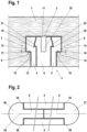
- Fig. 1
- zeigt ein Beispiel einer in einer flächigen Holzkonstruktion angeordneten Gratleisten-Vorrichtung im Schnitt;
- Fig. 2
- zeigt eine Ansicht derselben Gratleisten-Vorrichtung.
- In einer flächigen Holzkonstruktion 1 ist gemäss
Fig. 1 eine Gratnut 2 eingebracht. In dieser ist die Gratleisten-Vorrichtung 3 anzuordnen. Diese Gratleisten-Vorrichtung 3 ist mehrteilig, sie weist eine erste Gratleistenhälfte 4 und eine zweite Gratleistenhälfte 5 auf. Zwischen diesen beiden Gratleistenhälften 4 und 5 ist ein Sperrelement 6 einzusetzen. Die zwei Gratleistenhälften 4 und 5 können aus Metall bestehen, zum Beispiel aus Edelstahl. - Das Sperrelement 6 ist in der bevorzugten Ausführung des vorliegenden Ausführungsbeispiels aus einem elastischen oder gummielastischen Werkstoff gefertigt, beispielsweise Kunststoff, wie Polyurethan oder dergleichen. Nicht ausgeschlossen ist aber auch ein mehrteiliges Sperrelement 6, das aus Teilen unterschiedlicher Elastizität oder aus elastischen und nicht elastischen Teilen besteht. Letzteres kann beispielsweise auch einstückig durch Coextrusion von Kunststoffen mit unterschiedlichen Eigenschaften erfolgen.
- Die voneinander abzuwendenden Seiten 7 und 8 dieser beiden Gratleistenhälften 4 und 5 sind abgestuft ausgebildet, das heisst, sie weisen doppelte Abwinklungen 9 und 10 auf. Die beiden Gratleistenhälften 4 und 5 sind dabei in der vorliegenden Ausführung so auszurichten, dass deren zum Gratnutboden 11 hin ragende Bereich im Querschnitt breiter ist, als deren sich zur Gratnutöffnung 12 hin erstreckende Bereich. Die dadurch gebildeten Aussenwände 13 und 14 verlaufen annähernd parallel zueinander. Die jeweils durch die doppelten Abwinklungen 9 und 10 gebildeten Absätze 15 und 16 halten die beiden Gratleistenhälften 4 und 5 nicht nur in der Gratnut 2 gefangen, sondern sie fangen auch die in Richtung der Gratnutöffnung 12 treibenden Kräfte ab. Unerwünschte Spannungen zu den beiden Seiten hin, das heisst, in die flächige Holzkonstruktion 1, werden vermieden.
- Die Absätze 15 und 16 sind in der vorliegenden, bevorzugten Ausführung nicht rechtwinklig ausgeführt, sondern weisen jeweils eine Neigung 17 und 18 auf. Die Neigung 17 und 18 ist dabei so ausgebildet, dass das jeweils äussere Ende der beiden Absätze 15 und 16, das zu den Seiten 7 und 8 der beiden Gratleistenhälften 4 und 5 ausgerichtet ist, näher beim Gratnutboden 11 ist, während das innere Ende näher zur Gratnutöffnung 12 liegt. Das heisst, es ergibt sich eine Steigung in Richtung des in die Gratnut 2 einzusteckenden Endes der Gratleistenhälften 4 und 5. Die besagte Neigung 17 und 18 kann beispielsweise bis zu 15° betragen. Diese Formgebung erleichtert bei der Montage das Einfügen der beiden Gratleistenhälften 4 und 5 in der entsprechend geformten, zum Gratnutboden 11 hin im Querschnitt breiteren Gratnut 2.
- Die beiden Gratleistenhälften 4 und 5 sowie das Sperrelement 6 sind durch mindestens eine Rastverbindung miteinander verbunden. Das Sperrelement 6 weist hierzu in der vorliegenden Ausführung zu beiden Seiten, das heisst, zu den benachbarten Gratleistenhälften 4 und 5 hin, mindestens je eine Einrastung 19 und 20 auf. Diese bilden zusammen mit mindestens je einer Rastnase 21 und 22 der Gratleistenhälften 4 und 5 die besagte Rastverbindung. Es versteht sich von selbst, dass diese Rastverbindung auch umgekehrt ausgeführt sein könnte, das heisst, die Einrastungen am Sperrelement 6 und die Rastnasen an den Gratleistenhälften 4 und 5. Es könnte auch eine Mehrzahl von Rastverbindungen vorhanden sein. Um das Sperrelement beim Einschieben zusammendrücken zu können, kann in dieses vom einzuschiebenden Ende her mindestens ein Spalt 23 vorhanden sein.
- Gemäss der Ansicht nach
Fig. 2 kann das Sperrelement 6 bezüglich seiner Länge, also in seiner Längsachse 24 betrachtet, geteilt ausgeführt sein. Im vorliegenden Ausführungsbeispiel ist das Sperrelement 6 zweigeteilt. Theoretisch könnte dies auch für die Gratleistenhälften 4 und 5 der Fall sein. Die beiden Enden des Sperrelements 6, in der Längsachse 24 gesehen, können abgerundet sein und die jeweiligen Endkanten 25 der Gratleistenhälften 4 und 5 umgreifen, so dass in diesem Bereich je eine Schutzkappe 26 und 27 gebildet ist. Es sei hier festgehalten, dass diese Schutzkappe 26 und 27 auch als gegenüber dem Sperrelement 6 separate Bauteile ausgebildet sein könnten und nicht zwingend eine im Querschnitt halbkreisförmige Endfläche aufweisen müssen. Das ergibt in jedem Fall nicht nur einen saubereren Abschluss, sondern kann auch vor Verletzungen schützen, beispielsweise wenn unter einen Tisch oder ein Regalbrett gegriffen wird. Zudem erlauben die beiden Schutzkappen 26 und 27, da sie aus einem elastischen, beziehungsweise gummielastischen Werkstoff bestehen, Bewegungen der flächigen Holzkonstruktion 1 in Richtung der Längsachse 24 gegenüber den Endkanten 25 der Gratleistenhälften 4 und 5, die aus einem starren Werkstoff bestehen, zum Beispiel aus Metall, beziehungsweise Edelstahl. - Die relativ einfache Montage der erfindungsgemässen Gratleiste erfolgt wie folgt: Erstens, Einfräsen der Gratnut 2. Zweitens, Einsetzen der Gratleistenhälften 4 und 5. Drittens, Einstecken des Sperrelements 6.
- Das zeichnerisch dargestellte Ausführungsbeispiel bietet eine optimale und sehr einfach zu bedienende Lösung. Selbstverständlich liegt es aber im Rahmen der Erfindung nach den Patentansprüchen 1 die Gratleiste sowie deren Bauteile auch anders als gezeichnet auszubilden. Theoretisch wären auch Gratleistenhälften 4 und 5 denkbar, die mehrfach abgestuft ausgebildet sind. Die Gratnut 2 müsste dann ebenfalls eine entsprechende Geometrie aufweisen. Nicht zuletzt könnte die Geometrie der Gratnut 2 auch bezüglich des Gratnutbodens 11 anders ausgeführt sein, beispielsweise indem die Gratnut 2 tiefer in die flächige Holzkonstruktion 1 hineinragt, als die Gratleistenhälften 4 und 5 oder im Bereich dieser Gratleistenhälften 4 und 5 tiefer hineinragen, als im Bereich des Sperrelements 6.
-
- 1
- Flächige Holzkonstruktion
- 2
- Gratnut
- 3
- Gratleisten-Vorrichtung
- 4
- Erste Gratleistenhälfte
- 5
- Zweite Gratleistenhälfte
- 6
- Sperrelement
- 7
- Seite der ersten Gratleistenhälften 4
- 8
- Seite der zweiten Gratleistenhälften 5
- 9
- Abwinklung der ersten Gratleistenhälfte 4
- 10
- Abwinklung der zweiten Gratleistenhälfte 5
- 11
- Gratnutboden
- 12
- Gratnutöffnung
- 13
- Aussenwand der ersten Gratleistenhälfte 4
- 14
- Aussenwand der zweiten Gratleistenhälfte 5
- 15
- Absatz der ersten Gratleistenhälfte 4
- 16
- Absatz der zweiten Gratleistenhälfte 5
- 17
- Neigung des Absatzes der ersten Gratleistenhälfte 4
- 18
- Neigung des Absatzes der zweiten Gratleistenhälfte 5
- 19
- Einrastung der ersten Gratleistenhälfte 4
- 20
- Einrastung der zweiten Gratleistenhälfte 5
- 21
- Erste Rastnase des Sperrelements 6
- 22
- Zweite Rastnase des Sperrelements 6
- 23
- Spalt des Sperrelements 6
- 24
- Längsachse des Sperrelements 6
- 25
- Endkanten der Gratleistenhälften 4 und 5
- 26
- Erste Schutzkappe des Sperrelements 6
- 27
- Zweite Schutzkappe des Sperrelements 6
Claims (15)
- Gratleisten-Vorrichtung (3), aufweisend zwei in einer Gratnut (2) anzuordnende Gratleistenhälften (4, 5), dadurch gekennzeichnet, dass die in der Gratnut (2) voneinander abzuwendenden Seiten dieser beiden Gratleistenhälften (4, 5) durch Abwinklungen (9, 10) abgestuft ausgebildet sind, wobei mindestens ein Bereich gebildet ist, der im Querschnitt breiter ist, als ein zu einer Gratnutöffnung (12) zu richtender Bereich und wobei zwischen den zwei Gratleistenhälften (4, 5) ein Sperrelement (6) vorhanden ist, das mindestens teilweise aus einem elastischen Werkstoff besteht.
- Gratleisten-Vorrichtung nach Anspruch 1, dadurch gekennzeichnet, dass das mindestens eine Sperrelement (6) mindestens teilweise aus einem gummielastischen Werkstoff besteht.
- Gratleisten-Vorrichtung nach Anspruch 2, dadurch gekennzeichnet, dass das mindestens eine Sperrelement (6) mindestens teilweise aus einem Kunststoff, beispielsweise Polyurethan besteht.
- Gratleisten-Vorrichtung nach einem der Ansprüche 1 - 3, dadurch gekennzeichnet, dass durch die jeweilige Abwinklung (9, 10) der beiden Gratleistenhälften (4, 5) je ein Absatz (15, 16) gebildet ist.
- Gratleisten-Vorrichtung nach Anspruch 4, dadurch gekennzeichnet, dass vor und/oder nach den Absätzen (15, 16) liegende Aussenwände (13, 14) der beiden Gratleistenhälften (4, 5) im Wesentlichen parallel zueinander verlaufen.
- Gratleisten-Vorrichtung nach Anspruch 4 oder 5, dadurch gekennzeichnet, dass die beiden besagten Absätze (15, 16) jeweils eine Neigung (17, 18) aufweisen, wobei sich je eine Steigung in Richtung des in die Gratnut (2) einzuschiebenden Endes der Gratleistenhälften (4, 5) ergibt, mit dem Zweck, deren Einfügen in die entsprechend geformte Gratnut (2) zu erleichtern.
- Gratleisten-Vorrichtung nach Anspruch 6, dadurch gekennzeichnet, dass die besagte Neigung (17, 18) je bis zu 15° beträgt.
- Gratleisten-Vorrichtung nach einem der Ansprüche 1 - 7, dadurch gekennzeichnet, dass die beiden Gratleistenhälften (4, 5) und das mindestens eine Sperrelement (6) durch mindestens eine Rastverbindung miteinander verbunden sind, wobei je mindestens eine Einrastung (19, 20) mindestens je eine Rastnase (21, 22) vorhanden ist.
- Gratleisten-Vorrichtung nach einem der Ansprüche 1 - 8, dadurch gekennzeichnet, dass im mindestens einen Sperrelement (6) von einem in die Gratnut (2) einzuschiebenden Ende her mindestens ein Spalt (23) vorhanden ist, mit dem Zweck, das mindestens eine Sperrelement (6) beim Einschieben zusammendrücken zu können,
- Gratleisten-Vorrichtung nach einem der Ansprüche 1 - 9, dadurch gekennzeichnet, dass die jeweiligen Endkanten (25) der Gratleistenhälften (4, 5), in einer Längsachse (24) gesehen, durch mindestens eine Schutzkappe (25, 26) abgedeckt sind.
- Gratleisten-Vorrichtung nach Anspruch 10, dadurch gekennzeichnet, dass die Enden des Sperrelements (6), in einer Längsachse (24) gesehen, derart verbreitert sind, dass sie die jeweiligen Endkanten (25) der Gratleistenhälften (4, 5) umgreifen, so dass in diesem Bereich je eine Schutzkappe (25, 26) gebildet ist.
- Flächige Holzkonstruktion (1) mit einer Gratleisten-Vorrichtung (3) nach Anspruch 1, aufweisend zwei in einer Gratnut (2) anzuordnende Gratleistenhälften (4, 5), dadurch gekennzeichnet, dass in eine Fläche dieser flächigen Holzkonstruktion (1) eine Gratnut (2) eingebracht ist, die derart abgestuft ausgebildet ist, dass mindestens ein Bereich gebildet ist, der im Querschnitt breiter ist, als ein zu einer Gratnutöffnung (12) hin liegender Bereich, und dass die in dieser Gratnut (2) voneinander abzuwendenden Seiten dieser beiden Gratleistenhälften (4, 5) durch mindestens zwei Abwinklungen (9, 10) ebenfalls abgestuft (15, 16) ausgebildet sind, wobei mindestens ein Bereich gebildet ist, der im Querschnitt breiter ist, als ein zu einer Gratnutöffnung (12) zu richtender Bereich und wobei zwischen den zwei Gratleistenhälften (4, 5) ein Sperrelement (6) vorhanden ist, das mindestens teilweise aus einem elastischen Werkstoff besteht.
- Flächige Holzkonstruktion (1) nach Anspruch 12, dadurch gekennzeichnet, dass durch die jeweilige Abwinklung (9, 10) der Gratnut (2) und der beiden Gratleistenhälften (4, 5) je ein Absatz (15, 16) gebildet ist.
- Flächige Holzkonstruktion (1) nach Anspruch 13, dadurch gekennzeichnet, dass die besagten Absätze (15, 16) jeweils eine Neigung (17, 18) aufweisen, beispielsweise von bis zu 15°, wobei sich je eine Steigung in Richtung des Gratnutbodens (11) ergibt.
- Flächige Holzkonstruktion (1) nach Anspruch 13 oder 14, dadurch gekennzeichnet, dass die sowohl die Innenwände der Gratnut (2) als auch die Aussenwände (13, 14) der beiden Gratleistenhälften (4, 5) vor und/oder nach den Absätzen (15, 16) im Wesentlichen parallel zueinander verlaufen.
Applications Claiming Priority (1)
| Application Number | Priority Date | Filing Date | Title |
|---|---|---|---|
| CH000165/2022A CH719435A2 (de) | 2022-02-18 | 2022-02-18 | Gratleisten-Vorrichtung und flächige Holzkonstruktion mit dieser Gratleisten-Vorrichtung. |
Publications (2)
| Publication Number | Publication Date |
|---|---|
| EP4230882A1 true EP4230882A1 (de) | 2023-08-23 |
| EP4230882B1 EP4230882B1 (de) | 2025-06-04 |
Family
ID=85227215
Family Applications (1)
| Application Number | Title | Priority Date | Filing Date |
|---|---|---|---|
| EP23000019.2A Active EP4230882B1 (de) | 2022-02-18 | 2023-02-07 | Flächige holzkonstruktion mit einer gratleisten-vorrichtung |
Country Status (2)
| Country | Link |
|---|---|
| EP (1) | EP4230882B1 (de) |
| CH (1) | CH719435A2 (de) |
Citations (4)
| Publication number | Priority date | Publication date | Assignee | Title |
|---|---|---|---|---|
| DE1759662A1 (de) * | 1968-05-24 | 1971-06-16 | Reinke Fritz | Plattenverbindung fuer Massivplatten und Sandwichplatten |
| WO1995025898A1 (de) * | 1994-03-18 | 1995-09-28 | Friedrich Knapp Gesellschatt M.B.H. | Verbindungselement |
| DE10201565A1 (de) * | 2002-01-14 | 2003-07-24 | Draenert Studio Gmbh | Baueinheit mit wenigstens einem Grundelement |
| EP2641503B1 (de) * | 2012-03-23 | 2014-04-23 | Möbelfabrik Muotathal Paul von Rickenbach AG | Gratleiste für Brettflächen und Platten |
Family Cites Families (2)
| Publication number | Priority date | Publication date | Assignee | Title |
|---|---|---|---|---|
| DE102009050698A1 (de) * | 2009-10-26 | 2011-04-28 | San.Re.Mo Gmbh | Verbindungsvorrichtung für flächige Bauelemente |
| DE102015004686A1 (de) * | 2015-04-10 | 2016-10-13 | Ed. Heckewerth Nachf. GmbH & Co. KG | Möbelkorpus |
-
2022
- 2022-02-18 CH CH000165/2022A patent/CH719435A2/de unknown
-
2023
- 2023-02-07 EP EP23000019.2A patent/EP4230882B1/de active Active
Patent Citations (4)
| Publication number | Priority date | Publication date | Assignee | Title |
|---|---|---|---|---|
| DE1759662A1 (de) * | 1968-05-24 | 1971-06-16 | Reinke Fritz | Plattenverbindung fuer Massivplatten und Sandwichplatten |
| WO1995025898A1 (de) * | 1994-03-18 | 1995-09-28 | Friedrich Knapp Gesellschatt M.B.H. | Verbindungselement |
| DE10201565A1 (de) * | 2002-01-14 | 2003-07-24 | Draenert Studio Gmbh | Baueinheit mit wenigstens einem Grundelement |
| EP2641503B1 (de) * | 2012-03-23 | 2014-04-23 | Möbelfabrik Muotathal Paul von Rickenbach AG | Gratleiste für Brettflächen und Platten |
Also Published As
| Publication number | Publication date |
|---|---|
| CH719435A2 (de) | 2023-08-31 |
| EP4230882B1 (de) | 2025-06-04 |
Similar Documents
| Publication | Publication Date | Title |
|---|---|---|
| DE3017589A1 (de) | Verbindungsvorrichtung zum kantenseitigen verbinden von platten | |
| DE202007001781U1 (de) | Schubkasten | |
| DE102007019786A1 (de) | Verbindung für plattenförmige Bauelemente | |
| DE10135161B4 (de) | Kugelgelagerte Teleskopschiene | |
| EP3557084A1 (de) | Verbindungselement zum verbinden von profilelementen | |
| DE202013010931U1 (de) | Verbindung zweier Teile | |
| DE102008022511B4 (de) | Verbindung | |
| EP4230882B1 (de) | Flächige holzkonstruktion mit einer gratleisten-vorrichtung | |
| EP2601023B1 (de) | Bauplatte hergestellt durch verbinden von Teilstücken aus Holz | |
| DE2526300A1 (de) | Eckenverbindungsvorrichtung | |
| DE102018009235B4 (de) | Profilverbindung | |
| EP3453815B1 (de) | Terrassensystem und halteteil zum verbinden von mehreren terrassenprofilen | |
| EP3258121B1 (de) | Befestigungsvorrichtung zur befestigung zweier bauteile, insbesondere möbelteile oder möbelteilkomponenten, aneinander | |
| AT518135B1 (de) | Schubkasten für einen Spülenunterschrank | |
| DE102017129443B4 (de) | Verbindungssystem, insbesondere für Regale | |
| EP1983139B1 (de) | U-förmiger Steckverbinder | |
| DE3014567A1 (de) | Moebel-baukastensystem | |
| EP3478126B1 (de) | Einteilungssystem für ein bewegbares möbelteil | |
| CH479784A (de) | Aus Kastenprofilen zusammengesetzte Wand | |
| EP3114965B1 (de) | System aus profilschiene und frontplatte | |
| DE102007014794B4 (de) | Halteeinrichtung sowie Halteelement hierfür | |
| DE102004013887B4 (de) | Regal, Fachboden und Fachbodenträger für ein Regal | |
| DE202007007156U1 (de) | Leistenverbinder | |
| AT6387U1 (de) | Möbel | |
| DE7131548U (de) | Verbindungsteil für flächige Wandelemente |
Legal Events
| Date | Code | Title | Description |
|---|---|---|---|
| PUAI | Public reference made under article 153(3) epc to a published international application that has entered the european phase |
Free format text: ORIGINAL CODE: 0009012 |
|
| STAA | Information on the status of an ep patent application or granted ep patent |
Free format text: STATUS: THE APPLICATION HAS BEEN PUBLISHED |
|
| AK | Designated contracting states |
Kind code of ref document: A1 Designated state(s): AL AT BE BG CH CY CZ DE DK EE ES FI FR GB GR HR HU IE IS IT LI LT LU LV MC ME MK MT NL NO PL PT RO RS SE SI SK SM TR |
|
| STAA | Information on the status of an ep patent application or granted ep patent |
Free format text: STATUS: REQUEST FOR EXAMINATION WAS MADE |
|
| 17P | Request for examination filed |
Effective date: 20231002 |
|
| STAA | Information on the status of an ep patent application or granted ep patent |
Free format text: STATUS: EXAMINATION IS IN PROGRESS |
|
| 17Q | First examination report despatched |
Effective date: 20240514 |
|
| GRAP | Despatch of communication of intention to grant a patent |
Free format text: ORIGINAL CODE: EPIDOSNIGR1 |
|
| STAA | Information on the status of an ep patent application or granted ep patent |
Free format text: STATUS: GRANT OF PATENT IS INTENDED |
|
| INTG | Intention to grant announced |
Effective date: 20250325 |
|
| GRAS | Grant fee paid |
Free format text: ORIGINAL CODE: EPIDOSNIGR3 |
|
| GRAA | (expected) grant |
Free format text: ORIGINAL CODE: 0009210 |
|
| STAA | Information on the status of an ep patent application or granted ep patent |
Free format text: STATUS: THE PATENT HAS BEEN GRANTED |
|
| AK | Designated contracting states |
Kind code of ref document: B1 Designated state(s): AL AT BE BG CH CY CZ DE DK EE ES FI FR GB GR HR HU IE IS IT LI LT LU LV MC ME MK MT NL NO PL PT RO RS SE SI SK SM TR |
|
| REG | Reference to a national code |
Ref country code: GB Ref legal event code: FG4D Free format text: NOT ENGLISH |
|
| REG | Reference to a national code |
Ref country code: CH Ref legal event code: EP |
|
| REG | Reference to a national code |
Ref country code: DE Ref legal event code: R096 Ref document number: 502023001062 Country of ref document: DE |
|
| REG | Reference to a national code |
Ref country code: IE Ref legal event code: FG4D Free format text: LANGUAGE OF EP DOCUMENT: GERMAN |
|
| REG | Reference to a national code |
Ref country code: NL Ref legal event code: MP Effective date: 20250604 |
|
| PG25 | Lapsed in a contracting state [announced via postgrant information from national office to epo] |
Ref country code: FI Free format text: LAPSE BECAUSE OF FAILURE TO SUBMIT A TRANSLATION OF THE DESCRIPTION OR TO PAY THE FEE WITHIN THE PRESCRIBED TIME-LIMIT Effective date: 20250604 Ref country code: ES Free format text: LAPSE BECAUSE OF FAILURE TO SUBMIT A TRANSLATION OF THE DESCRIPTION OR TO PAY THE FEE WITHIN THE PRESCRIBED TIME-LIMIT Effective date: 20250604 |
|
| REG | Reference to a national code |
Ref country code: LT Ref legal event code: MG9D |
|
| PG25 | Lapsed in a contracting state [announced via postgrant information from national office to epo] |
Ref country code: NO Free format text: LAPSE BECAUSE OF FAILURE TO SUBMIT A TRANSLATION OF THE DESCRIPTION OR TO PAY THE FEE WITHIN THE PRESCRIBED TIME-LIMIT Effective date: 20250904 Ref country code: GR Free format text: LAPSE BECAUSE OF FAILURE TO SUBMIT A TRANSLATION OF THE DESCRIPTION OR TO PAY THE FEE WITHIN THE PRESCRIBED TIME-LIMIT Effective date: 20250905 |
|
| PG25 | Lapsed in a contracting state [announced via postgrant information from national office to epo] |
Ref country code: PL Free format text: LAPSE BECAUSE OF FAILURE TO SUBMIT A TRANSLATION OF THE DESCRIPTION OR TO PAY THE FEE WITHIN THE PRESCRIBED TIME-LIMIT Effective date: 20250604 |
|
| PG25 | Lapsed in a contracting state [announced via postgrant information from national office to epo] |
Ref country code: BG Free format text: LAPSE BECAUSE OF FAILURE TO SUBMIT A TRANSLATION OF THE DESCRIPTION OR TO PAY THE FEE WITHIN THE PRESCRIBED TIME-LIMIT Effective date: 20250604 |
|
| PG25 | Lapsed in a contracting state [announced via postgrant information from national office to epo] |
Ref country code: HR Free format text: LAPSE BECAUSE OF FAILURE TO SUBMIT A TRANSLATION OF THE DESCRIPTION OR TO PAY THE FEE WITHIN THE PRESCRIBED TIME-LIMIT Effective date: 20250604 |
|
| PG25 | Lapsed in a contracting state [announced via postgrant information from national office to epo] |
Ref country code: RS Free format text: LAPSE BECAUSE OF FAILURE TO SUBMIT A TRANSLATION OF THE DESCRIPTION OR TO PAY THE FEE WITHIN THE PRESCRIBED TIME-LIMIT Effective date: 20250904 |
|
| PG25 | Lapsed in a contracting state [announced via postgrant information from national office to epo] |
Ref country code: LV Free format text: LAPSE BECAUSE OF FAILURE TO SUBMIT A TRANSLATION OF THE DESCRIPTION OR TO PAY THE FEE WITHIN THE PRESCRIBED TIME-LIMIT Effective date: 20250604 |
|
| PG25 | Lapsed in a contracting state [announced via postgrant information from national office to epo] |
Ref country code: NL Free format text: LAPSE BECAUSE OF FAILURE TO SUBMIT A TRANSLATION OF THE DESCRIPTION OR TO PAY THE FEE WITHIN THE PRESCRIBED TIME-LIMIT Effective date: 20250604 |
|
| PG25 | Lapsed in a contracting state [announced via postgrant information from national office to epo] |
Ref country code: PT Free format text: LAPSE BECAUSE OF FAILURE TO SUBMIT A TRANSLATION OF THE DESCRIPTION OR TO PAY THE FEE WITHIN THE PRESCRIBED TIME-LIMIT Effective date: 20251006 |
|
| PG25 | Lapsed in a contracting state [announced via postgrant information from national office to epo] |
Ref country code: IS Free format text: LAPSE BECAUSE OF FAILURE TO SUBMIT A TRANSLATION OF THE DESCRIPTION OR TO PAY THE FEE WITHIN THE PRESCRIBED TIME-LIMIT Effective date: 20251004 |
|
| PG25 | Lapsed in a contracting state [announced via postgrant information from national office to epo] |
Ref country code: SM Free format text: LAPSE BECAUSE OF FAILURE TO SUBMIT A TRANSLATION OF THE DESCRIPTION OR TO PAY THE FEE WITHIN THE PRESCRIBED TIME-LIMIT Effective date: 20250604 |
|
| PG25 | Lapsed in a contracting state [announced via postgrant information from national office to epo] |
Ref country code: CZ Free format text: LAPSE BECAUSE OF FAILURE TO SUBMIT A TRANSLATION OF THE DESCRIPTION OR TO PAY THE FEE WITHIN THE PRESCRIBED TIME-LIMIT Effective date: 20250604 |
|
| PG25 | Lapsed in a contracting state [announced via postgrant information from national office to epo] |
Ref country code: EE Free format text: LAPSE BECAUSE OF FAILURE TO SUBMIT A TRANSLATION OF THE DESCRIPTION OR TO PAY THE FEE WITHIN THE PRESCRIBED TIME-LIMIT Effective date: 20250604 |
|
| PG25 | Lapsed in a contracting state [announced via postgrant information from national office to epo] |
Ref country code: SK Free format text: LAPSE BECAUSE OF FAILURE TO SUBMIT A TRANSLATION OF THE DESCRIPTION OR TO PAY THE FEE WITHIN THE PRESCRIBED TIME-LIMIT Effective date: 20250604 |
|
| PG25 | Lapsed in a contracting state [announced via postgrant information from national office to epo] |
Ref country code: IT Free format text: LAPSE BECAUSE OF FAILURE TO SUBMIT A TRANSLATION OF THE DESCRIPTION OR TO PAY THE FEE WITHIN THE PRESCRIBED TIME-LIMIT Effective date: 20250604 |
|
| REG | Reference to a national code |
Ref country code: CH Ref legal event code: U11 Free format text: ST27 STATUS EVENT CODE: U-0-0-U10-U11 (AS PROVIDED BY THE NATIONAL OFFICE) Effective date: 20260301 |
|
| REG | Reference to a national code |
Ref country code: DE Ref legal event code: R097 Ref document number: 502023001062 Country of ref document: DE |
|
| PLBE | No opposition filed within time limit |
Free format text: ORIGINAL CODE: 0009261 |
|
| STAA | Information on the status of an ep patent application or granted ep patent |
Free format text: STATUS: NO OPPOSITION FILED WITHIN TIME LIMIT |
|
| PG25 | Lapsed in a contracting state [announced via postgrant information from national office to epo] |
Ref country code: DK Free format text: LAPSE BECAUSE OF FAILURE TO SUBMIT A TRANSLATION OF THE DESCRIPTION OR TO PAY THE FEE WITHIN THE PRESCRIBED TIME-LIMIT Effective date: 20250604 |
|
| PGFP | Annual fee paid to national office [announced via postgrant information from national office to epo] |
Ref country code: DE Payment date: 20260228 Year of fee payment: 4 |
|
| PGFP | Annual fee paid to national office [announced via postgrant information from national office to epo] |
Ref country code: AT Payment date: 20260301 Year of fee payment: 4 |
|
| REG | Reference to a national code |
Ref country code: CH Ref legal event code: L10 Free format text: ST27 STATUS EVENT CODE: U-0-0-L10-L00 (AS PROVIDED BY THE NATIONAL OFFICE) Effective date: 20260416 |
|
| PGFP | Annual fee paid to national office [announced via postgrant information from national office to epo] |
Ref country code: CH Payment date: 20260301 Year of fee payment: 4 |
|
| 26N | No opposition filed |
Effective date: 20260305 |
|
| PG25 | Lapsed in a contracting state [announced via postgrant information from national office to epo] |
Ref country code: LT Free format text: LAPSE BECAUSE OF FAILURE TO SUBMIT A TRANSLATION OF THE DESCRIPTION OR TO PAY THE FEE WITHIN THE PRESCRIBED TIME-LIMIT Effective date: 20250604 |
|
| PG25 | Lapsed in a contracting state [announced via postgrant information from national office to epo] |
Ref country code: SE Free format text: LAPSE BECAUSE OF FAILURE TO SUBMIT A TRANSLATION OF THE DESCRIPTION OR TO PAY THE FEE WITHIN THE PRESCRIBED TIME-LIMIT Effective date: 20250604 |