EP4230240A2 - Pompe électro-osmotique - Google Patents
Pompe électro-osmotique Download PDFInfo
- Publication number
- EP4230240A2 EP4230240A2 EP23181473.2A EP23181473A EP4230240A2 EP 4230240 A2 EP4230240 A2 EP 4230240A2 EP 23181473 A EP23181473 A EP 23181473A EP 4230240 A2 EP4230240 A2 EP 4230240A2
- Authority
- EP
- European Patent Office
- Prior art keywords
- liquid medicine
- check valve
- combined
- electrode
- diaphragm
- Prior art date
- Legal status (The legal status is an assumption and is not a legal conclusion. Google has not performed a legal analysis and makes no representation as to the accuracy of the status listed.)
- Pending
Links
Images


Classifications
-
- F—MECHANICAL ENGINEERING; LIGHTING; HEATING; WEAPONS; BLASTING
- F04—POSITIVE - DISPLACEMENT MACHINES FOR LIQUIDS; PUMPS FOR LIQUIDS OR ELASTIC FLUIDS
- F04B—POSITIVE-DISPLACEMENT MACHINES FOR LIQUIDS; PUMPS
- F04B19/00—Machines or pumps having pertinent characteristics not provided for in, or of interest apart from, groups F04B1/00 - F04B17/00
- F04B19/006—Micropumps
-
- A—HUMAN NECESSITIES
- A61—MEDICAL OR VETERINARY SCIENCE; HYGIENE
- A61M—DEVICES FOR INTRODUCING MEDIA INTO, OR ONTO, THE BODY; DEVICES FOR TRANSDUCING BODY MEDIA OR FOR TAKING MEDIA FROM THE BODY; DEVICES FOR PRODUCING OR ENDING SLEEP OR STUPOR
- A61M5/00—Devices for bringing media into the body in a subcutaneous, intra-vascular or intramuscular way; Accessories therefor, e.g. filling or cleaning devices, arm-rests
- A61M5/14—Infusion devices, e.g. infusing by gravity; Blood infusion; Accessories therefor
- A61M5/142—Pressure infusion, e.g. using pumps
- A61M5/14244—Pressure infusion, e.g. using pumps adapted to be carried by the patient, e.g. portable on the body
- A61M5/14248—Pressure infusion, e.g. using pumps adapted to be carried by the patient, e.g. portable on the body of the skin patch type
-
- A—HUMAN NECESSITIES
- A61—MEDICAL OR VETERINARY SCIENCE; HYGIENE
- A61M—DEVICES FOR INTRODUCING MEDIA INTO, OR ONTO, THE BODY; DEVICES FOR TRANSDUCING BODY MEDIA OR FOR TAKING MEDIA FROM THE BODY; DEVICES FOR PRODUCING OR ENDING SLEEP OR STUPOR
- A61M5/00—Devices for bringing media into the body in a subcutaneous, intra-vascular or intramuscular way; Accessories therefor, e.g. filling or cleaning devices, arm-rests
- A61M5/14—Infusion devices, e.g. infusing by gravity; Blood infusion; Accessories therefor
- A61M5/142—Pressure infusion, e.g. using pumps
- A61M5/145—Pressure infusion, e.g. using pumps using pressurised reservoirs, e.g. pressurised by means of pistons
-
- A—HUMAN NECESSITIES
- A61—MEDICAL OR VETERINARY SCIENCE; HYGIENE
- A61M—DEVICES FOR INTRODUCING MEDIA INTO, OR ONTO, THE BODY; DEVICES FOR TRANSDUCING BODY MEDIA OR FOR TAKING MEDIA FROM THE BODY; DEVICES FOR PRODUCING OR ENDING SLEEP OR STUPOR
- A61M39/00—Tubes, tube connectors, tube couplings, valves, access sites or the like, specially adapted for medical use
- A61M39/22—Valves or arrangement of valves
- A61M39/24—Check- or non-return valves
-
- A—HUMAN NECESSITIES
- A61—MEDICAL OR VETERINARY SCIENCE; HYGIENE
- A61M—DEVICES FOR INTRODUCING MEDIA INTO, OR ONTO, THE BODY; DEVICES FOR TRANSDUCING BODY MEDIA OR FOR TAKING MEDIA FROM THE BODY; DEVICES FOR PRODUCING OR ENDING SLEEP OR STUPOR
- A61M5/00—Devices for bringing media into the body in a subcutaneous, intra-vascular or intramuscular way; Accessories therefor, e.g. filling or cleaning devices, arm-rests
- A61M5/14—Infusion devices, e.g. infusing by gravity; Blood infusion; Accessories therefor
- A61M5/142—Pressure infusion, e.g. using pumps
- A61M5/145—Pressure infusion, e.g. using pumps using pressurised reservoirs, e.g. pressurised by means of pistons
- A61M5/14586—Pressure infusion, e.g. using pumps using pressurised reservoirs, e.g. pressurised by means of pistons pressurised by means of a flexible diaphragm
- A61M5/14593—Pressure infusion, e.g. using pumps using pressurised reservoirs, e.g. pressurised by means of pistons pressurised by means of a flexible diaphragm the diaphragm being actuated by fluid pressure
-
- F—MECHANICAL ENGINEERING; LIGHTING; HEATING; WEAPONS; BLASTING
- F04—POSITIVE - DISPLACEMENT MACHINES FOR LIQUIDS; PUMPS FOR LIQUIDS OR ELASTIC FLUIDS
- F04B—POSITIVE-DISPLACEMENT MACHINES FOR LIQUIDS; PUMPS
- F04B19/00—Machines or pumps having pertinent characteristics not provided for in, or of interest apart from, groups F04B1/00 - F04B17/00
-
- A—HUMAN NECESSITIES
- A61—MEDICAL OR VETERINARY SCIENCE; HYGIENE
- A61M—DEVICES FOR INTRODUCING MEDIA INTO, OR ONTO, THE BODY; DEVICES FOR TRANSDUCING BODY MEDIA OR FOR TAKING MEDIA FROM THE BODY; DEVICES FOR PRODUCING OR ENDING SLEEP OR STUPOR
- A61M5/00—Devices for bringing media into the body in a subcutaneous, intra-vascular or intramuscular way; Accessories therefor, e.g. filling or cleaning devices, arm-rests
- A61M5/14—Infusion devices, e.g. infusing by gravity; Blood infusion; Accessories therefor
- A61M5/142—Pressure infusion, e.g. using pumps
- A61M5/145—Pressure infusion, e.g. using pumps using pressurised reservoirs, e.g. pressurised by means of pistons
- A61M2005/14513—Pressure infusion, e.g. using pumps using pressurised reservoirs, e.g. pressurised by means of pistons with secondary fluid driving or regulating the infusion
-
- A—HUMAN NECESSITIES
- A61—MEDICAL OR VETERINARY SCIENCE; HYGIENE
- A61M—DEVICES FOR INTRODUCING MEDIA INTO, OR ONTO, THE BODY; DEVICES FOR TRANSDUCING BODY MEDIA OR FOR TAKING MEDIA FROM THE BODY; DEVICES FOR PRODUCING OR ENDING SLEEP OR STUPOR
- A61M39/00—Tubes, tube connectors, tube couplings, valves, access sites or the like, specially adapted for medical use
- A61M39/22—Valves or arrangement of valves
- A61M39/24—Check- or non-return valves
- A61M2039/2433—Valve comprising a resilient or deformable element, e.g. flap valve, deformable disc
-
- B—PERFORMING OPERATIONS; TRANSPORTING
- B01—PHYSICAL OR CHEMICAL PROCESSES OR APPARATUS IN GENERAL
- B01L—CHEMICAL OR PHYSICAL LABORATORY APPARATUS FOR GENERAL USE
- B01L2400/00—Moving or stopping fluids
- B01L2400/04—Moving fluids with specific forces or mechanical means
- B01L2400/0403—Moving fluids with specific forces or mechanical means specific forces
- B01L2400/0415—Moving fluids with specific forces or mechanical means specific forces electrical forces, e.g. electrokinetic
- B01L2400/0418—Moving fluids with specific forces or mechanical means specific forces electrical forces, e.g. electrokinetic electro-osmotic flow [EOF]
Definitions
- the present invention relates to a patch-type liquid medicine delivery device attached to a human body or an electro-osmosis pump for transmission of liquid medicine, which may be applied to a wearable medical device.
- An electro-osmosis pump is a pump that uses a phenomenon of fluid movement which occurs when a voltage is applied to opposite ends of a capillary or a porous separation membrane.
- the electro-osmosis pump can be manufactured to be very small in size compared to a general mechanical pump, and generates no noise and consumes less power.
- the above-stated patent discloses a liquid medicine delivery device in which electrodes are formed at opposite ends of the ceramic separation membrane, and when a predetermined potential is applied to the electrodes, a pressure that corresponds to the corresponding potential is generated and the device uses the pressure.
- the liquid medicine delivery device additionally uses two electric fluid chambers and a needle for injection of liquid medicine.
- the electro osmosis pump used in the liquid medicine delivery device has a structure in which liquid medicine to be delivered and water, which is an operation fluid used for driving of the pump are separated from each other by oil, and thus unexpected mixing of the liquid medicine and water may occur at any time in an interface between the liquid medicine and water.
- liquid medicine which is an object to be delivered, and water, which is an operation fluid, need to be separated from each other.
- Liquid medicine is a mixture of various substances, and a biologically active substance in components of the mixture may be oxidized or reduced in a potential for driving of the electro osmosis pump.
- a high molecular substance such as protein is adsorbed to the electrodes, thereby deteriorating performance of the pump, and accordingly, it is preferable that the electrodes and the liquid medicine need to be separated from each other.
- an amount of power to be consumed for driving of the pump is a factor that determines practical utility when the pump is applied to a patch-type liquid medicine delivery device or a wearable medical device attached to a human body, and accordingly, a small-sized pump, which can be driven with low power, is required.
- the present invention has been made in an effort to resolve the above-described problems, and provides an electro osmosis pump that can be stably driven by preventing liquid medicine, which is an object to be delivered, and operation fluid from being mixed with each other, thereby improving merchantability, and can prevent a side effect thereby the therapeutic effect for a patient.
- Another purpose of the present invention is to provide an electro osmosis pump that can maximize fluid transfer efficiency with respect to power consumption.
- the present invention provides an electro osmosis pump that includes: a connector provided with a liquid medicine inlet and a liquid medicine outlet; a check valve assembly combined to one side of the connector; and a driver that is connected to the other side of the connector and moves the liquid medicine toward the liquid medicine outlet by applying pressure to the liquid medicine while being separated from the liquid medicine, which passes through the check valve assembly.
- the check valve assembly may include: an inflow check valve that is disposed in the liquid medicine inlet to move the liquid medicine in one direction; and an discharge check valve that is disposed in the liquid medicine outlet to discharge the liquid medicine delivered through the inflow check valve.
- the check valve assembly is combined to the connector and includes a liquid medicine inflow extension pipeline and a liquid medicine discharge extension pipeline, the liquid medicine inflow extension pipeline is connected to the liquid medicine inlet and the liquid medicine discharge extension pipeline is connected to the liquid medicine outlet, and an inflow check valve is disposed in the liquid medicine discharge extension pipeline and a discharge check valve is disposed in the liquid medicine discharge extension pipeline.
- a first fixing hole that fixes the inflow check valve is formed in the liquid medicine inflow extension pipeline, and a second fixing hole that fixes the discharge check valve is formed in the liquid medicine discharge extension pipeline.
- the driver includes: a first diaphragm that is combined to the connector and blocks liquid medicine of the check valve assembly; a first pump housing that is combined to the first diaphragm and provided with a space where an operation fluid is received; a first power supply line that is combined to the first pump housing and receives power; a first electrode connected to the first power supply line; a membrane of which one side is combined to the first electrode; a second electrode combined to the other side of the membrane; a second power supply line that supplies power to the second electrode; a second pump housing combined to one side of the second electrode and provided with a space where an operation fluid is received; and a second diaphragm combined to the second pump housing.
- the first pump housing is provided with a space that penetrates along an axial direction and the space of the first pump housing is blocked by the first diaphragm and the first electrode
- the second pump housing is provided with another space that penetrates along the axial direction and the space of the second pump housing is blocked by the second electrode and the second diaphragm.
- a space in which liquid medicine is introduced into through the liquid medicine inlet and discharged through the liquid medicine inlet is formed between the connector and the first diaphragm.
- the membrane is formed of a porous material through which an operation fluid and ions can be transferred.
- the membrane is preferably formed of an insulator.
- the first diaphragm or the second diaphragm is provided with a wrinkle portion that is formed as protrusions and depressions.
- a pump operation fluid and a fluid to be delivered such as liquid medicine are separated from each other by a flexible diaphragm and thus an active component included in the fluid to be delivered can be prevented from being spoiled due to an electro-chemical reaction by a voltage applied to an electrode.
- a component included in the pump operation fluid can be prevented from being fixed with the liquid medicine, and thus various transfer fluids can be applied in design of a patch-type liquid medicine delivery device, thereby increasing the degree of freedom in a design. That is, the present invention enables the design of a patch-type liquid medicine delivery device that can selectively supply an optimum liquid medicine to a patient suffering from a specific disease such as diabetes, or can be applied to patients suffering from various diseases.
- the present invention provides an effect of improving merchantability of the electro osmosis pump driven with low power and high efficiency by applying a check value having a very low opening pressure and increasing a reaction speed of the check value.
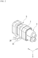
- FIG. 1 and FIG. 2 are perspective view provided for description of an exemplary embodiment of the present invention
- FIG. 3 is an exploded perspective view of FIG. 1
- FIG. 4 is a cross-sectional view of FIG. 1 , taken along the line IV-IV
- FIG. 5 is a cross-sectional view of FIG. 1 , taken along the line V-V, which illustrates an electro-osmosis pump.
- An electro-osmosis pump includes a connector 1, a check valve assembly 3, and a driver 5.
- the check valve assembly 3 may be combined to one side of the connector 1 and the driver may be combined to the other side of the connector 1.
- the connector 1 is provided with a barrier rib 1a that partitions the check valve assembly 3 and the driver 5.
- the barrier rib 1a includes a liquid medicine inlet 1b and a liquid medicine outlet 1c.
- the liquid medicine inlet 1b and the liquid medicine outlet 1c are disposed at a distance from each other, and penetrate the barrier rib 1a.
- Liquid medicine to be injected into a human body is put into the liquid medicine inlet 1b, and the liquid medicine outlet 1c may be a path through which the liquid medicine put into the liquid medicine inlet 1b is discharged so as to be injected back into the human body.
- the check valve assembly 3 may include a valve housing 7, an inflow check valve 9, a discharge check valve 11, a first fixing hole 13, and a second fixing hole 15.
- the valve housing 7 includes a liquid medicine inflow extension pipeline 7a and a liquid medicine discharge extension pipeline 7b.
- the valve housing 7 may be combined to one side of the connector 1.
- the liquid medicine inflow extension pipeline 7a is connected to the liquid medicine inlet 1b
- the liquid medicine discharge extension pipeline 7b is connected to the liquid medicine outlet 1c.
- the inflow check valve 9 is disposed in the liquid medicine inflow extension pipeline 7a.
- the inflow check valve 9 may let liquid medicine injected into a human body pass to the liquid medicine inlet 1b and block movement of the liquid medicine in the reverse direction.
- the discharge check valve 11 is disposed in the liquid medicine discharge extension pipeline 7b.
- the discharge check valve 11 may let the liquid medicine passed through the liquid medicine inlet 1b pass in a direction of injection into the human body, and blocks movement in the reverse direction.
- duckbill valves that are flexible and have a low open-pressure may be used. Fluid transmission efficiency compared to a power consumption amount is increased by the inflow check valve 9 and the discharge check valve 11, thereby enabling long-time operation and improving productivity.
- the first fixing hole 13 is fitted into the liquid medicine inflow extension pipeline 7a to fix the inflow check valve 9.
- the second fixing hole 15 is fitted into the liquid medicine discharge extension pipeline 7b to fix the discharge check valve 11.
- first fixing hole 13 and the second fixing hole 15 preferably have pipelines through which liquid medicine can pass.
- the inflow check valve 9 and the discharge check valve 11 are combined to the valve housing 7, but this is not restrictive, and the inflow check valve 9 and the discharge check valve 11 may be respectively combined to the liquid medicine inlet 1b and the liquid medicine outlet 1c provided in the connector 1.
- the valve housing 7 is integrally formed with the connector 1 so that it can be manufactured with a simpler structure. According to the other exemplary embodiment of the present invention, the number of parts is reduced so that manufacturing cost can be more saved, and the product can be manufactured to be more compact.
- the driver 5 is combined to one side of the connector 1.
- the driver 5 is preferably disposed opposite to a side where the check valve assembly 3 is combined.
- the driver 5 is preferably disposed apart from the liquid medicine that passes through the check valve assembly 3.
- the driver 5 applies pressure to the liquid medicine passed through the check valve assembly 3 such that the liquid medicine can pass through the liquid medicine outlet 1c.
- the driver 5 may include a first diaphragm 17, a first pump housing 19, a first power supply line 21, a first electrode 23, a membrane 25, a second electrode 27, a second power supply line 29, a second pump housing 31, and a second diaphragm 33.
- the first diaphragm 17 is combined to one side of the connector 1. A space is provided between the first diaphragm 17 and the connector 1. That is, the first diaphragm 17 is combined to the connector 1, while maintaining a certain space in the connector 1. Thus, liquid medicine at the check valve assembly 3 maintains a state of being isolated rather than moving toward the driver 5 by the first diaphragm 17.
- a wrinkle portion may be provided in the first diaphragm 17 to allow the plane to smoothly move along the axial direction (i.e., the x-axis direction in FIG. 1 ).
- the first diaphragm 17 is combined to one side of the first pump housing 19.
- the first pump housing 19 is provided with a space 19a that penetrates along an axial direction. Thus, one side of the space 19a of the first pump housing 19 may be closed by the first diaphragm 17.
- the first electrode 23 is combined to the other side of the first pump housing 19 so that the space 19a formed by the first pump housing 19 may be closed.
- the first pump housing 19 may accommodate operation fluid such as water and the like in the space 19a provided therein.
- the first pump housing 19 may be provided with a fluid injection hole portion 19b at an external circumference thereof. Such a hole portion 19b may be sealed after the operation fluid is injected into the first pump housing 19. Thus, the operation fluid of the driver 5 may be separated from the liquid medicine at the check valve assembly 3.
- the first power supply line 21 may supply power to the first electrode 23.
- the first power supply line 21 is disposed along an edge of the first pump housing 19, and may be fixed to the first electrode 23 by contacting the same.
- the first power supply line 21 is preferably disposed between the first pump housing 19 and the first electrode 23.
- the first power supply line 21 may supply power to the first electrode 23, and may be disposed between the first electrode 23 and the membrane 25.
- the first electrode 23 is formed in the shape of a plate and thus may close the space 19a of the first pump housing 19. That is, the first pump housing 19 may form the space 19a with the first diaphragm 17 and the first electrode 23.
- the operation fluid such as water and the like is accommodated in the space 69a of the first pump housing 19.
- the membrane 25 may be formed of a porous material through which the operation fluid and ions can be tranferred.
- the membrane 25 is preferably made of an insulator such as a ceramic and the like.
- an electro-chemical reaction material used in the first electrode 23 and the second electrode 27 is consumed or desorbed due to long-term driving of the electro-osmosis pump and thus the porous membrane 25 is exposed.
- a side reaction such as electrolysis of water, which occurs due to exposure to carbon paper or carbon cloth, does not occur.
- unnecessary power consumption due to a side reaction can be prevented. Therefore, according to the present invention, a safe driving characteristic can be provided and durability can be improved.
- the membrane 25 may be used by processing a flexible non-conductive material such as a polymer resin, rubber, urethane, or a plastic film into a thin film form.
- the second electrode 77 is disposed at the other side of the membrane 75. That is, the membrane 25 is preferably disposed between the first electrode 23 and the second electrode 27.
- the second power supply line 29 may supply external power to the second electrode 27.
- the second power supply line 29 may be combined to an edge of the second pump housing 31.
- the second power supply line 29 may have any alignment structure as long as it has a structure for supplying power to the second electrode 27.
- the shape of the second pump housing 31 is the same as or similar to the shape of the first pump housing 19. Another space 31a that penetrates the second pump housing 31 along an axial direction is provided in the second pump housing 31. As in the first pump housing 19, a hole portion 31b that penetrates the space 31a may be provided in the second pump housing 31. The hole portion 31b of the second pump housing 31 may be sealed by a sealant or filled by welding and the like after operation fluid is injected therein.
- the second diaphragm 33 is combined to one side of the second pump housing 31 and thus may close the space 31a provided in the second pump housing 31.
- the second pump housing 31 may close the space 31a by using the second electrode 27, which is formed in the shape of a plate, and the second diaphragm 33.
- a wrinkle portion 33a may be formed in a plane of the second diaphragm 33.
- the wrinkle portion 33a formed in the second diaphragm 33 may be formed of protrusions and depressions that protrude in the axial direction with reference to a cross-section.
- the wrinkle portion 33a of the second diaphragm 33 enhances performance of pumping by sufficiently moving the plane of the second diaphragm 33 along the axial direction.
- the wrinkle portion 33a is formed in the second diaphragm 33, but depending on exemplary embodiments, a wrinkle portion may be also formed in the first diaphragm 17.
- a wrinkle portion that can be formed in the first diaphragm 17 or the second diaphragm 33 maximizes deformation of the first diaphragm 17 and the second diaphragm 33 with small energy, thereby reducing energy consumption. That is, the driver 5 can be driven for a long period of time with a small external power source.
- the above-described first pump housing 19, the first power supply line 21, the first electrode 23, the membrane 25, the second electrode 27, the second power supply line 29, and the second pump housing 31 may be air-tightly sealed from the outside by an encapsulant S.
- the first power supply line 21, the first electrode 23, the membrane 25, the second electrode 27, and the second power supply line 29 are formed relatively smaller than the first pump housing 19 and the second pump housing 31 in size, and thus the encapsulant S may be disposed in a circumferential portion (i.e., a portion exposed to the outside and a portion that forms a groove or a space with reference to a cross-section) between the first pump housing 19 and the second pump housing 31 while the first power supply line 21, the first electrode 23, the membrane 25, the second electrode 27, and the second power supply line 29 are in an assembled state.
- Such an encapsulant S may form an encapsulation layer that maintains air-tight encapsulation from the outside.
- an adhesive such as a hot melt adhesive, an epoxy adhesive, a polyurethane adhesive, or a cyanoacrylate adhesive may be used.
- the encapsulant is not limited to such examples, and any material that is rigidly cured to prevent leakage of operation fluid and prevent deformation of an external appearance of a configuration element is applicable.
- first power supply line 21 and the second power supply line 29 have different polarities, and a voltage difference occurs between the first electrode 23 and the second electrode 27. Due to such a voltage difference, positive ions are generated as a result of an electrode reaction in an anode.
- the positive ions generated from the above-stated reaction move to a cathode and pass through the membrane 25 while pulling the operation fluid together such that a pressure (a pumping force) is generated.
- the operation fluid can be iteratively moved to the space 69a of the first pump housing 19 and the space 31a of the second pump housing 31 by the above-described electrochemical reaction.
- an electro-chemical reactant consumed when the electrode is used as an anode can be recovered when the electrode is used as a cathode, and vice versa. Accordingly, the electro-osmosis pump can be continuously driven.
- first diaphragm 17 and the second diaphragm 33 are deformed and a pressure is generated. Such a pressure is applied to a space between the connector 1 and the first diaphragm 17.
- the liquid medicine is introduced into the liquid medicine inlet 1b through the liquid medicine inflow extension pipeline 7a by the pressure.
- the introduced liquid medicine may be injected into a human body while being discharged along the liquid medicine outlet 1c and the liquid medicine discharge extension pipeline 7b.
- the inflow check valve 9 and the discharge check valve 11 allow the liquid medicine to move along only one direction.
- the electro-osmosis pump according to the exemplary embodiment of the present invention can safely inject liquid medicine into a human body while using low power.
- the electro-osmosis pump 5 of the exemplary embodiment of the present invention can prevent an active component included in the liquid medicine from being spoiled due to an electro-chemical reaction.
- a component included in the operation fluid of the driver 55 can be prevented from being transmitted to the liquid medicine such that a wider range of liquid medicine or operation fluid is applicable.
- a check valve of which an opening pressure is very low is used so that a reaction speed of the check valve is very fast, and accordingly, the pump can be driven with low power and high efficiency as a whole
Landscapes
- Health & Medical Sciences (AREA)
- Engineering & Computer Science (AREA)
- Heart & Thoracic Surgery (AREA)
- Public Health (AREA)
- Veterinary Medicine (AREA)
- Biomedical Technology (AREA)
- Hematology (AREA)
- Life Sciences & Earth Sciences (AREA)
- Animal Behavior & Ethology (AREA)
- General Health & Medical Sciences (AREA)
- Anesthesiology (AREA)
- Vascular Medicine (AREA)
- Mechanical Engineering (AREA)
- General Engineering & Computer Science (AREA)
- Pulmonology (AREA)
- Dermatology (AREA)
- Physics & Mathematics (AREA)
- Fluid Mechanics (AREA)
- Reciprocating Pumps (AREA)
- Infusion, Injection, And Reservoir Apparatuses (AREA)
- Separation Using Semi-Permeable Membranes (AREA)
Applications Claiming Priority (3)
| Application Number | Priority Date | Filing Date | Title |
|---|---|---|---|
| KR1020160112131A KR101910932B1 (ko) | 2016-08-31 | 2016-08-31 | 전기 삼투 펌프 |
| PCT/KR2017/008292 WO2018043927A1 (fr) | 2016-08-31 | 2017-08-01 | Pompe électro-osmotique |
| EP17846852.6A EP3508234B1 (fr) | 2016-08-31 | 2017-08-01 | Pompe électro-osmotique |
Related Parent Applications (2)
| Application Number | Title | Priority Date | Filing Date |
|---|---|---|---|
| EP17846852.6A Division EP3508234B1 (fr) | 2016-08-31 | 2017-08-01 | Pompe électro-osmotique |
| EP17846852.6A Division-Into EP3508234B1 (fr) | 2016-08-31 | 2017-08-01 | Pompe électro-osmotique |
Publications (2)
| Publication Number | Publication Date |
|---|---|
| EP4230240A2 true EP4230240A2 (fr) | 2023-08-23 |
| EP4230240A3 EP4230240A3 (fr) | 2023-08-30 |
Family
ID=61301348
Family Applications (2)
| Application Number | Title | Priority Date | Filing Date |
|---|---|---|---|
| EP17846852.6A Active EP3508234B1 (fr) | 2016-08-31 | 2017-08-01 | Pompe électro-osmotique |
| EP23181473.2A Pending EP4230240A3 (fr) | 2016-08-31 | 2017-08-01 | Pompe électro-osmotique |
Family Applications Before (1)
| Application Number | Title | Priority Date | Filing Date |
|---|---|---|---|
| EP17846852.6A Active EP3508234B1 (fr) | 2016-08-31 | 2017-08-01 | Pompe électro-osmotique |
Country Status (6)
| Country | Link |
|---|---|
| US (2) | US11286918B2 (fr) |
| EP (2) | EP3508234B1 (fr) |
| JP (2) | JP6792058B2 (fr) |
| KR (1) | KR101910932B1 (fr) |
| CN (2) | CN114534013A (fr) |
| WO (1) | WO2018043927A1 (fr) |
Families Citing this family (19)
| Publication number | Priority date | Publication date | Assignee | Title |
|---|---|---|---|---|
| KR20240010960A (ko) * | 2022-07-18 | 2024-01-25 | 이오플로우(주) | 전기 삼투 펌프 시스템 및 투석 시스템 |
| JP7157241B2 (ja) * | 2018-08-20 | 2022-10-19 | イオフロー カンパニーリミテッド | 電気浸透圧ポンプ |
| KR102101938B1 (ko) * | 2018-08-20 | 2020-04-17 | 이오플로우(주) | 펌프 |
| KR102173812B1 (ko) * | 2019-08-20 | 2020-11-04 | 이오플로우(주) | 전기 삼투압 펌프 |
| US11587839B2 (en) | 2019-06-27 | 2023-02-21 | Analog Devices, Inc. | Device with chemical reaction chamber |
| KR102477258B1 (ko) * | 2019-08-20 | 2022-12-14 | 이오플로우(주) | 전기 삼투압 펌프 |
| CN110755699A (zh) * | 2019-09-18 | 2020-02-07 | 浙江省北大信息技术高等研究院 | 可植入的电渗微泵装置 |
| KR102452513B1 (ko) * | 2019-12-23 | 2022-10-11 | 이오플로우(주) | 복막 투석 디바이스 |
| KR20210116750A (ko) * | 2020-03-13 | 2021-09-28 | 이오플로우(주) | 전기 삼투 펌프용 막-전극 어셈블리, 이를 포함하는 전기 삼투 펌프 및 유체 펌핑 시스템 |
| US11712516B2 (en) | 2020-04-17 | 2023-08-01 | Analog Devices, Inc. | Fluid delivery device |
| KR102534944B1 (ko) * | 2020-10-27 | 2023-05-30 | 이오플로우(주) | 전기 삼투압 펌프 |
| KR102619175B1 (ko) * | 2021-02-26 | 2023-12-29 | 이오플로우(주) | 펌프 |
| KR102336073B1 (ko) | 2021-03-02 | 2021-12-07 | 박철 | 구동제어기구 및 이를 이용한 약물주입장치 |
| US11604084B2 (en) | 2021-04-15 | 2023-03-14 | Analog Devices, Inc. | Sensor package |
| US11796367B2 (en) | 2021-05-07 | 2023-10-24 | Analog Devices, Inc. | Fluid control system |
| KR20230097705A (ko) * | 2021-12-24 | 2023-07-03 | 이오플로우(주) | 펌프 |
| KR20230097707A (ko) * | 2021-12-24 | 2023-07-03 | 이오플로우(주) | 전기 삼투압 펌프 |
| KR20230097709A (ko) * | 2021-12-24 | 2023-07-03 | 이오플로우(주) | 전기 삼투압 펌프 |
| CN114632218B (zh) * | 2022-03-14 | 2024-03-08 | 重庆倍加医疗器械有限公司 | 一种气压驱动注射装置 |
Citations (1)
| Publication number | Priority date | Publication date | Assignee | Title |
|---|---|---|---|---|
| WO2011112723A2 (fr) | 2010-03-09 | 2011-09-15 | Board Of Regents Of The University Of Texas System | Pompes électro-osmotiques, systèmes, procédés et compositions |
Family Cites Families (36)
| Publication number | Priority date | Publication date | Assignee | Title |
|---|---|---|---|---|
| JPS5283007U (fr) * | 1975-12-19 | 1977-06-21 | ||
| JPS5283007A (en) | 1975-12-29 | 1977-07-11 | Fujitsu Ltd | Calling detection system |
| DE3817404C2 (de) * | 1988-05-21 | 1997-08-07 | Stihl Maschf Andreas | Membrankraftstoffpumpe für einen mit einem Membranvergaser ausgerüsteten Verbrennungsmotor einer Motorkettensäge |
| KR100283405B1 (ko) * | 1998-12-28 | 2001-03-02 | 정휘동 | 정수기용 승압펌프 |
| US6413238B1 (en) * | 1999-09-17 | 2002-07-02 | Baxter International Inc | Fluid dispenser with stabilized fluid flow |
| GB0030929D0 (en) * | 2000-12-19 | 2001-01-31 | Inverness Medical Ltd | Analyte measurement |
| TW561223B (en) * | 2001-04-24 | 2003-11-11 | Matsushita Electric Works Ltd | Pump and its producing method |
| WO2007005565A2 (fr) * | 2002-05-01 | 2007-01-11 | Microlin, Llc | Dispositif de distribution de fluide comprenant une pompe electrochimique pourvue d'une membrane d'echange ionique et procede associe |
| US7470267B2 (en) * | 2002-05-01 | 2008-12-30 | Microlin, Llc | Fluid delivery device having an electrochemical pump with an anionic exchange membrane and associated method |
| US7517440B2 (en) * | 2002-07-17 | 2009-04-14 | Eksigent Technologies Llc | Electrokinetic delivery systems, devices and methods |
| KR20060099520A (ko) * | 2003-10-21 | 2006-09-19 | 노보 노르디스크 에이/에스 | 의료용 피부 장착 장치 |
| EP1527792A1 (fr) * | 2003-10-27 | 2005-05-04 | Novo Nordisk A/S | Dispositif d'injection médicale montable sur la peau |
| CN101365885B (zh) * | 2004-04-21 | 2011-08-03 | 艾克西根特技术有限公司 | 电动输送系统、装置和方法 |
| KR100578972B1 (ko) | 2004-06-30 | 2006-05-12 | 삼성에스디아이 주식회사 | 플라즈마 디스플레이 패널 |
| US7104767B2 (en) * | 2004-07-19 | 2006-09-12 | Wilson Greatbatch Technologies, Inc. | Diaphragm pump for medical applications |
| JP4544114B2 (ja) * | 2004-12-22 | 2010-09-15 | パナソニック電工株式会社 | ダイヤフラムポンプ液体吐出制御装置 |
| EP1828601A1 (fr) * | 2004-12-22 | 2007-09-05 | Matsushita Electric Works, Ltd. | Appareil de regulation des debits de liquide |
| JP4497021B2 (ja) * | 2005-04-25 | 2010-07-07 | パナソニック電工株式会社 | 圧電ダイヤフラムポンプ |
| EP1904035A4 (fr) * | 2005-07-01 | 2013-01-16 | Microlin Llc | Dispositif de distribution de fluide comprenant une pompe electrochimique pourvue d'une membrane d'echange ionique et procede associe |
| US20070021734A1 (en) * | 2005-07-15 | 2007-01-25 | Sai Bhavaraju | Bioelectro-osmotic engine fluid delivery device |
| US20070021735A1 (en) * | 2005-07-15 | 2007-01-25 | Sai Bhavaraju | Dual membrane electro-osmotic fluid delivery device |
| US8273075B2 (en) * | 2005-12-13 | 2012-09-25 | The Invention Science Fund I, Llc | Osmotic pump with remotely controlled osmotic flow rate |
| DE102006009424A1 (de) * | 2006-02-24 | 2007-09-06 | Universität Rostock | Elektrohydrodynamische Mikropumpe und deren Verwendung |
| CA3177048A1 (fr) * | 2007-10-12 | 2009-04-23 | Deka Products Limited Partnership | Appareil et procedes d'hemodialyse |
| EP2344792B1 (fr) * | 2008-10-09 | 2019-12-04 | Watts Water Technologies, Inc. | Soupape d' arrêt pour un système de filtration d' eau par osmose inverse |
| KR101106286B1 (ko) * | 2009-11-02 | 2012-01-18 | 경북대학교 산학협력단 | 전기삼투식 약물 펌프 및 그 시스템 |
| JP2014523499A (ja) | 2011-05-05 | 2014-09-11 | エクシジェント テクノロジーズ, エルエルシー | 往復動界面動電ポンプの差動圧力制御のシステムおよび方法 |
| KR101333136B1 (ko) * | 2012-01-10 | 2013-11-26 | 윌로펌프 주식회사 | 전수로형 펌프 |
| WO2014112726A1 (fr) * | 2013-01-15 | 2014-07-24 | 서강대학교산학협력단 | Pompe électro-osmotique utilisant une réaction d'électrode réversible et système de pompage de fluide l'utilisant |
| KR101420360B1 (ko) * | 2013-07-30 | 2014-07-16 | 서강대학교산학협력단 | 가역적 전극반응을 이용한 전기삼투펌프 및 이를 이용한 유체 펌핑 시스템 |
| JP6193656B2 (ja) * | 2013-07-11 | 2017-09-06 | 株式会社テクノ高槻 | 電磁振動型流体ポンプ |
| WO2015030466A1 (fr) * | 2013-08-26 | 2015-03-05 | 서강대학교산학협력단 | Pompe électro-osmotique et système de pompage de fluide la comprenant |
| KR101457629B1 (ko) * | 2013-08-26 | 2014-11-07 | 서강대학교산학협력단 | 전기삼투펌프 및 이를 포함하는 유체 펌핑 시스템 |
| KR101554810B1 (ko) * | 2014-01-09 | 2015-09-21 | 강원대학교산학협력단 | 삼투압 약물주입펌프 |
| JP6349134B2 (ja) * | 2014-04-11 | 2018-06-27 | 東京理化器械株式会社 | ダイヤフラム真空ポンプ |
| JP6733420B2 (ja) * | 2016-08-23 | 2020-07-29 | セイコーエプソン株式会社 | 逆止弁、ダイアフラムポンプ、および印刷装置 |
-
2016
- 2016-08-31 KR KR1020160112131A patent/KR101910932B1/ko active IP Right Grant
-
2017
- 2017-08-01 US US16/326,768 patent/US11286918B2/en active Active
- 2017-08-01 EP EP17846852.6A patent/EP3508234B1/fr active Active
- 2017-08-01 WO PCT/KR2017/008292 patent/WO2018043927A1/fr unknown
- 2017-08-01 CN CN202210179400.8A patent/CN114534013A/zh active Pending
- 2017-08-01 EP EP23181473.2A patent/EP4230240A3/fr active Pending
- 2017-08-01 JP JP2019511604A patent/JP6792058B2/ja active Active
- 2017-08-01 CN CN201780052756.2A patent/CN109715233B/zh active Active
-
2020
- 2020-11-05 JP JP2020184874A patent/JP7097632B2/ja active Active
-
2022
- 2022-02-23 US US17/652,139 patent/US11725640B2/en active Active
Patent Citations (1)
| Publication number | Priority date | Publication date | Assignee | Title |
|---|---|---|---|---|
| WO2011112723A2 (fr) | 2010-03-09 | 2011-09-15 | Board Of Regents Of The University Of Texas System | Pompes électro-osmotiques, systèmes, procédés et compositions |
Also Published As
| Publication number | Publication date |
|---|---|
| US20190184095A1 (en) | 2019-06-20 |
| KR20180024990A (ko) | 2018-03-08 |
| CN109715233A (zh) | 2019-05-03 |
| JP2021020127A (ja) | 2021-02-18 |
| EP3508234A1 (fr) | 2019-07-10 |
| KR101910932B1 (ko) | 2018-10-23 |
| EP4230240A3 (fr) | 2023-08-30 |
| JP6792058B2 (ja) | 2020-11-25 |
| CN114534013A (zh) | 2022-05-27 |
| EP3508234A4 (fr) | 2020-02-12 |
| WO2018043927A1 (fr) | 2018-03-08 |
| CN109715233B (zh) | 2022-03-18 |
| US20220170447A1 (en) | 2022-06-02 |
| US11286918B2 (en) | 2022-03-29 |
| JP7097632B2 (ja) | 2022-07-08 |
| JP2019528137A (ja) | 2019-10-10 |
| EP3508234B1 (fr) | 2023-10-04 |
| US11725640B2 (en) | 2023-08-15 |
Similar Documents
| Publication | Publication Date | Title |
|---|---|---|
| US11725640B2 (en) | Electroosmotic pump | |
| US11738137B2 (en) | Liquid medicine injection device | |
| KR101488408B1 (ko) | 전기삼투펌프 및 이를 포함하는 유체 펌핑 시스템 | |
| WO2014036112A4 (fr) | Dispositifs microfluidiques actionnés de façon électrochimique | |
| JP2021534345A (ja) | 電気浸透圧ポンプ | |
| CN112654383B (zh) | 电渗泵 | |
| CN113904521A (zh) | 多级电渗微泵 | |
| US20230077910A1 (en) | Electroosmotic pump | |
| Sheybani et al. | Rapid and repeated bolus drug delivery enabled by high efficiency electrochemical bellows actuators | |
| TWM627591U (zh) | 用於藥劑遞送的電化學幫浦及其藥劑遞送裝置 | |
| KR20210022514A (ko) | 전기 삼투압 펌프 | |
| KR20240010960A (ko) | 전기 삼투 펌프 시스템 및 투석 시스템 | |
| WO2023078293A1 (fr) | Pompe électrochimique pour l'administration de médicament, et dispositif d'administration de médicament associé | |
| TWI840716B (zh) | 用於藥劑遞送的電化學幫浦及其藥劑遞送裝置 | |
| KR20240040447A (ko) | 전기 삼투 펌프 | |
| AU2022381167A1 (en) | Electrochemical pump for medicament delivery, and medicament delivery device thereof | |
| JP2011144692A (ja) | 導電性高分子を用いた流体搬送装置 | |
| TW202319080A (zh) | 用於藥劑遞送的電化學幫浦及其藥劑遞送裝置 | |
| KR20230097709A (ko) | 전기 삼투압 펌프 | |
| KR20230097707A (ko) | 전기 삼투압 펌프 | |
| WO2020041373A1 (fr) | Dispositif de pompage de liquide par électrolyse dans un corps compact | |
| KR20170083398A (ko) | 약액 주입 장치 및 방법 |
Legal Events
| Date | Code | Title | Description |
|---|---|---|---|
| PUAI | Public reference made under article 153(3) epc to a published international application that has entered the european phase |
Free format text: ORIGINAL CODE: 0009012 |
|
| STAA | Information on the status of an ep patent application or granted ep patent |
Free format text: STATUS: THE APPLICATION HAS BEEN PUBLISHED |
|
| PUAL | Search report despatched |
Free format text: ORIGINAL CODE: 0009013 |
|
| AC | Divisional application: reference to earlier application |
Ref document number: 3508234 Country of ref document: EP Kind code of ref document: P |
|
| AK | Designated contracting states |
Kind code of ref document: A2 Designated state(s): AL AT BE BG CH CY CZ DE DK EE ES FI FR GB GR HR HU IE IS IT LI LT LU LV MC MK MT NL NO PL PT RO RS SE SI SK SM TR |
|
| AK | Designated contracting states |
Kind code of ref document: A3 Designated state(s): AL AT BE BG CH CY CZ DE DK EE ES FI FR GB GR HR HU IE IS IT LI LT LU LV MC MK MT NL NO PL PT RO RS SE SI SK SM TR |
|
| RIC1 | Information provided on ipc code assigned before grant |
Ipc: F04B 19/00 20060101ALI20230721BHEP Ipc: A61M 39/24 20060101ALI20230721BHEP Ipc: A61M 5/145 20060101ALI20230721BHEP Ipc: A61M 5/142 20060101AFI20230721BHEP |