EP4229704B1 - Propagationsbarriere mit verstärkendem füllmaterial und verfahren zu deren herstellung - Google Patents
Propagationsbarriere mit verstärkendem füllmaterial und verfahren zu deren herstellung Download PDFInfo
- Publication number
- EP4229704B1 EP4229704B1 EP22822959.7A EP22822959A EP4229704B1 EP 4229704 B1 EP4229704 B1 EP 4229704B1 EP 22822959 A EP22822959 A EP 22822959A EP 4229704 B1 EP4229704 B1 EP 4229704B1
- Authority
- EP
- European Patent Office
- Prior art keywords
- protective layer
- barrier according
- barrier
- weight
- heat
- Prior art date
- Legal status (The legal status is an assumption and is not a legal conclusion. Google has not performed a legal analysis and makes no representation as to the accuracy of the status listed.)
- Active
Links
Images

Classifications
-
- B—PERFORMING OPERATIONS; TRANSPORTING
- B32—LAYERED PRODUCTS
- B32B—LAYERED PRODUCTS, i.e. PRODUCTS BUILT-UP OF STRATA OF FLAT OR NON-FLAT, e.g. CELLULAR OR HONEYCOMB, FORM
- B32B27/00—Layered products comprising a layer of synthetic resin
- B32B27/06—Layered products comprising a layer of synthetic resin as the main or only constituent of a layer, which is next to another layer of the same or of a different material
- B32B27/065—Layered products comprising a layer of synthetic resin as the main or only constituent of a layer, which is next to another layer of the same or of a different material of foam
-
- B—PERFORMING OPERATIONS; TRANSPORTING
- B32—LAYERED PRODUCTS
- B32B—LAYERED PRODUCTS, i.e. PRODUCTS BUILT-UP OF STRATA OF FLAT OR NON-FLAT, e.g. CELLULAR OR HONEYCOMB, FORM
- B32B3/00—Layered products comprising a layer with external or internal discontinuities or unevennesses, or a layer of non-planar shape; Layered products comprising a layer having particular features of form
- B32B3/26—Layered products comprising a layer with external or internal discontinuities or unevennesses, or a layer of non-planar shape; Layered products comprising a layer having particular features of form characterised by a particular shape of the outline of the cross-section of a continuous layer; characterised by a layer with cavities or internal voids ; characterised by an apertured layer
- B32B3/266—Layered products comprising a layer with external or internal discontinuities or unevennesses, or a layer of non-planar shape; Layered products comprising a layer having particular features of form characterised by a particular shape of the outline of the cross-section of a continuous layer; characterised by a layer with cavities or internal voids ; characterised by an apertured layer characterised by an apertured layer, the apertures going through the whole thickness of the layer, e.g. expanded metal, perforated layer, slit layer regular cells B32B3/12
-
- B—PERFORMING OPERATIONS; TRANSPORTING
- B32—LAYERED PRODUCTS
- B32B—LAYERED PRODUCTS, i.e. PRODUCTS BUILT-UP OF STRATA OF FLAT OR NON-FLAT, e.g. CELLULAR OR HONEYCOMB, FORM
- B32B5/00—Layered products characterised by the non- homogeneity or physical structure, i.e. comprising a fibrous, filamentary, particulate or foam layer; Layered products characterised by having a layer differing constitutionally or physically in different parts
- B32B5/18—Layered products characterised by the non- homogeneity or physical structure, i.e. comprising a fibrous, filamentary, particulate or foam layer; Layered products characterised by having a layer differing constitutionally or physically in different parts characterised by features of a layer of foamed material
-
- C—CHEMISTRY; METALLURGY
- C08—ORGANIC MACROMOLECULAR COMPOUNDS; THEIR PREPARATION OR CHEMICAL WORKING-UP; COMPOSITIONS BASED THEREON
- C08K—Use of inorganic or non-macromolecular organic substances as compounding ingredients
- C08K3/00—Use of inorganic substances as compounding ingredients
- C08K3/18—Oxygen-containing compounds, e.g. metal carbonyls
- C08K3/24—Acids; Salts thereof
- C08K3/26—Carbonates; Bicarbonates
-
- C—CHEMISTRY; METALLURGY
- C08—ORGANIC MACROMOLECULAR COMPOUNDS; THEIR PREPARATION OR CHEMICAL WORKING-UP; COMPOSITIONS BASED THEREON
- C08L—COMPOSITIONS OF MACROMOLECULAR COMPOUNDS
- C08L5/00—Compositions of polysaccharides or of their derivatives not provided for in groups C08L1/00 or C08L3/00
- C08L5/04—Alginic acid; Derivatives thereof
-
- C—CHEMISTRY; METALLURGY
- C09—DYES; PAINTS; POLISHES; NATURAL RESINS; ADHESIVES; COMPOSITIONS NOT OTHERWISE PROVIDED FOR; APPLICATIONS OF MATERIALS NOT OTHERWISE PROVIDED FOR
- C09K—MATERIALS FOR MISCELLANEOUS APPLICATIONS, NOT PROVIDED FOR ELSEWHERE
- C09K5/00—Heat-transfer, heat-exchange or heat-storage materials, e.g. refrigerants; Materials for the production of heat or cold by chemical reactions other than by combustion
- C09K5/08—Materials not undergoing a change of physical state when used
- C09K5/14—Solid materials, e.g. powdery or granular
-
- F—MECHANICAL ENGINEERING; LIGHTING; HEATING; WEAPONS; BLASTING
- F16—ENGINEERING ELEMENTS AND UNITS; GENERAL MEASURES FOR PRODUCING AND MAINTAINING EFFECTIVE FUNCTIONING OF MACHINES OR INSTALLATIONS; THERMAL INSULATION IN GENERAL
- F16L—PIPES; JOINTS OR FITTINGS FOR PIPES; SUPPORTS FOR PIPES, CABLES OR PROTECTIVE TUBING; MEANS FOR THERMAL INSULATION IN GENERAL
- F16L59/00—Thermal insulation in general
- F16L59/02—Shape or form of insulating materials, with or without coverings integral with the insulating materials
-
- H—ELECTRICITY
- H01—ELECTRIC ELEMENTS
- H01M—PROCESSES OR MEANS, e.g. BATTERIES, FOR THE DIRECT CONVERSION OF CHEMICAL ENERGY INTO ELECTRICAL ENERGY
- H01M10/00—Secondary cells; Manufacture thereof
- H01M10/05—Accumulators with non-aqueous electrolyte
- H01M10/052—Li-accumulators
- H01M10/0525—Rocking-chair batteries, i.e. batteries with lithium insertion or intercalation in both electrodes; Lithium-ion batteries
-
- H—ELECTRICITY
- H01—ELECTRIC ELEMENTS
- H01M—PROCESSES OR MEANS, e.g. BATTERIES, FOR THE DIRECT CONVERSION OF CHEMICAL ENERGY INTO ELECTRICAL ENERGY
- H01M10/00—Secondary cells; Manufacture thereof
- H01M10/42—Methods or arrangements for servicing or maintenance of secondary cells or secondary half-cells
- H01M10/4207—Methods or arrangements for servicing or maintenance of secondary cells or secondary half-cells for several batteries or cells simultaneously or sequentially
-
- H—ELECTRICITY
- H01—ELECTRIC ELEMENTS
- H01M—PROCESSES OR MEANS, e.g. BATTERIES, FOR THE DIRECT CONVERSION OF CHEMICAL ENERGY INTO ELECTRICAL ENERGY
- H01M10/00—Secondary cells; Manufacture thereof
- H01M10/60—Heating or cooling; Temperature control
- H01M10/65—Means for temperature control structurally associated with the cells
- H01M10/658—Means for temperature control structurally associated with the cells by thermal insulation or shielding
-
- H—ELECTRICITY
- H01—ELECTRIC ELEMENTS
- H01M—PROCESSES OR MEANS, e.g. BATTERIES, FOR THE DIRECT CONVERSION OF CHEMICAL ENERGY INTO ELECTRICAL ENERGY
- H01M10/00—Secondary cells; Manufacture thereof
- H01M10/60—Heating or cooling; Temperature control
- H01M10/65—Means for temperature control structurally associated with the cells
- H01M10/659—Means for temperature control structurally associated with the cells by heat storage or buffering, e.g. heat capacity or liquid-solid phase changes or transition
-
- H—ELECTRICITY
- H01—ELECTRIC ELEMENTS
- H01M—PROCESSES OR MEANS, e.g. BATTERIES, FOR THE DIRECT CONVERSION OF CHEMICAL ENERGY INTO ELECTRICAL ENERGY
- H01M50/00—Constructional details or processes of manufacture of the non-active parts of electrochemical cells other than fuel cells, e.g. hybrid cells
- H01M50/20—Mountings; Secondary casings or frames; Racks, modules or packs; Suspension devices; Shock absorbers; Transport or carrying devices; Holders
- H01M50/204—Racks, modules or packs for multiple batteries or multiple cells
- H01M50/207—Racks, modules or packs for multiple batteries or multiple cells characterised by their shape
- H01M50/209—Racks, modules or packs for multiple batteries or multiple cells characterised by their shape adapted for prismatic or rectangular cells
-
- B—PERFORMING OPERATIONS; TRANSPORTING
- B32—LAYERED PRODUCTS
- B32B—LAYERED PRODUCTS, i.e. PRODUCTS BUILT-UP OF STRATA OF FLAT OR NON-FLAT, e.g. CELLULAR OR HONEYCOMB, FORM
- B32B2264/00—Composition or properties of particles which form a particulate layer or are present as additives
- B32B2264/10—Inorganic particles
- B32B2264/104—Oxysalt, e.g. carbonate, sulfate, phosphate or nitrate particles
-
- B—PERFORMING OPERATIONS; TRANSPORTING
- B32—LAYERED PRODUCTS
- B32B—LAYERED PRODUCTS, i.e. PRODUCTS BUILT-UP OF STRATA OF FLAT OR NON-FLAT, e.g. CELLULAR OR HONEYCOMB, FORM
- B32B2266/00—Composition of foam
- B32B2266/02—Organic
-
- B—PERFORMING OPERATIONS; TRANSPORTING
- B32—LAYERED PRODUCTS
- B32B—LAYERED PRODUCTS, i.e. PRODUCTS BUILT-UP OF STRATA OF FLAT OR NON-FLAT, e.g. CELLULAR OR HONEYCOMB, FORM
- B32B2266/00—Composition of foam
- B32B2266/12—Gel
- B32B2266/122—Hydrogel, i.e. a gel containing an aqueous composition
-
- B—PERFORMING OPERATIONS; TRANSPORTING
- B32—LAYERED PRODUCTS
- B32B—LAYERED PRODUCTS, i.e. PRODUCTS BUILT-UP OF STRATA OF FLAT OR NON-FLAT, e.g. CELLULAR OR HONEYCOMB, FORM
- B32B2307/00—Properties of the layers or laminate
- B32B2307/30—Properties of the layers or laminate having particular thermal properties
- B32B2307/306—Resistant to heat
-
- B—PERFORMING OPERATIONS; TRANSPORTING
- B32—LAYERED PRODUCTS
- B32B—LAYERED PRODUCTS, i.e. PRODUCTS BUILT-UP OF STRATA OF FLAT OR NON-FLAT, e.g. CELLULAR OR HONEYCOMB, FORM
- B32B2307/00—Properties of the layers or laminate
- B32B2307/70—Other properties
- B32B2307/724—Permeability to gases, adsorption
- B32B2307/7242—Non-permeable
- B32B2307/7246—Water vapor barrier
-
- B—PERFORMING OPERATIONS; TRANSPORTING
- B32—LAYERED PRODUCTS
- B32B—LAYERED PRODUCTS, i.e. PRODUCTS BUILT-UP OF STRATA OF FLAT OR NON-FLAT, e.g. CELLULAR OR HONEYCOMB, FORM
- B32B2307/00—Properties of the layers or laminate
- B32B2307/70—Other properties
- B32B2307/732—Dimensional properties
- B32B2307/737—Dimensions, e.g. volume or area
- B32B2307/7375—Linear, e.g. length, distance or width
- B32B2307/7376—Thickness
-
- B—PERFORMING OPERATIONS; TRANSPORTING
- B32—LAYERED PRODUCTS
- B32B—LAYERED PRODUCTS, i.e. PRODUCTS BUILT-UP OF STRATA OF FLAT OR NON-FLAT, e.g. CELLULAR OR HONEYCOMB, FORM
- B32B2457/00—Electrical equipment
- B32B2457/10—Batteries
-
- B—PERFORMING OPERATIONS; TRANSPORTING
- B32—LAYERED PRODUCTS
- B32B—LAYERED PRODUCTS, i.e. PRODUCTS BUILT-UP OF STRATA OF FLAT OR NON-FLAT, e.g. CELLULAR OR HONEYCOMB, FORM
- B32B2571/00—Protective equipment
-
- C—CHEMISTRY; METALLURGY
- C08—ORGANIC MACROMOLECULAR COMPOUNDS; THEIR PREPARATION OR CHEMICAL WORKING-UP; COMPOSITIONS BASED THEREON
- C08K—Use of inorganic or non-macromolecular organic substances as compounding ingredients
- C08K3/00—Use of inorganic substances as compounding ingredients
- C08K3/18—Oxygen-containing compounds, e.g. metal carbonyls
- C08K3/24—Acids; Salts thereof
- C08K3/26—Carbonates; Bicarbonates
- C08K2003/265—Calcium, strontium or barium carbonate
-
- C—CHEMISTRY; METALLURGY
- C08—ORGANIC MACROMOLECULAR COMPOUNDS; THEIR PREPARATION OR CHEMICAL WORKING-UP; COMPOSITIONS BASED THEREON
- C08L—COMPOSITIONS OF MACROMOLECULAR COMPOUNDS
- C08L2203/00—Applications
- C08L2203/20—Applications use in electrical or conductive gadgets
-
- Y—GENERAL TAGGING OF NEW TECHNOLOGICAL DEVELOPMENTS; GENERAL TAGGING OF CROSS-SECTIONAL TECHNOLOGIES SPANNING OVER SEVERAL SECTIONS OF THE IPC; TECHNICAL SUBJECTS COVERED BY FORMER USPC CROSS-REFERENCE ART COLLECTIONS [XRACs] AND DIGESTS
- Y02—TECHNOLOGIES OR APPLICATIONS FOR MITIGATION OR ADAPTATION AGAINST CLIMATE CHANGE
- Y02E—REDUCTION OF GREENHOUSE GAS [GHG] EMISSIONS, RELATED TO ENERGY GENERATION, TRANSMISSION OR DISTRIBUTION
- Y02E60/00—Enabling technologies; Technologies with a potential or indirect contribution to GHG emissions mitigation
- Y02E60/10—Energy storage using batteries
Definitions
- the present invention relates to a barrier for preventing the propagation of a thermal event within a multi-cell battery module (so-called "propagation barrier”), comprising a heat-absorbing protective layer based on a hydrogel and a reinforcing filler material. Furthermore, the invention relates to a battery module comprising the barrier and to the use of the barrier to compensate for volume fluctuations within a battery module. Furthermore, a method for producing the propagation barrier is also specified.
- Thermal events can occur in all battery types.
- One of the most feared thermal events is thermal runaway. This can occur when the rate at which the battery generates heat exceeds the rate at which it can be dissipated. If a critical temperature is exceeded, the heat-generating process inside the battery intensifies, causing the battery to heat up to several hundred degrees Celsius within a very short time. At the same time, there is an extreme increase in pressure within the cell, which can result in an explosive release of decomposition gases and a fire.
- the danger posed by such a thermal event is exacerbated.
- the distance between the individual cells does not provide sufficient protection against the propagation of thermal runaway. Due to the high temperature reached by the cell affected by thermal runaway, the adjacent cells also heat up beyond the critical temperature. Accordingly, the thermal runaway of a single cell can easily lead to the destruction of the entire battery module.
- Lithium-ion batteries are particularly susceptible to thermal runaway. These batteries have a significantly higher energy density than other battery types and can potentially release decomposition gases containing a high proportion of oxygen, which can lead to even higher temperatures in the event of a failure. In applications where battery module space is critical, many battery manufacturers have increased the packing density of lithium-ion cells to the extreme. This leaves little space available for barriers to prevent the propagation of thermal events, which in many cases results in insufficient thermal insulation between the cells.
- the WO 2010/017169 A1 also addresses the problem of thermal runaway in multi-cell battery packs, particularly lithium-ion battery packs, and proposes strategies for preventing the transmission of a thermal event from one battery cell to a neighboring battery cell.
- a propagation barrier with a hydrogel as a heat-absorbing material is specified.
- the hydrogel is stored in a flexible pouch or a rigid container and inserted into the battery module.
- the flexible pouch adapts to the shape of the battery cells to ensure the transfer of heat from the battery cell to the hydrogel.
- the container can be customized to also establish contact with the cell surface.
- both of these features require improvement.
- the element can only function as a barrier to a limited extent.
- the hydrogel In the embodiment in which the hydrogel is stored in a pouch, there is no spacer between the cells that would survive the thermal runaway of an adjacent cell. Once the water evaporates and the hydrogel matrix material decomposes, neighboring cells can come into direct contact with each other. In the embodiment in which the hydrogel is stored in a container, the cells are not in direct contact with each other, but the container walls, made of a solid material, form a thermal bridge across which the thermal event can propagate after the water contained in the hydrogel has evaporated.
- the CN 105 169 613 A recommends the use of hydrogel comprising 0.5–40 parts by mass of hydrogel material and at least 50 parts by mass of water in lithium batteries. Specifically, the hydrogel is applied to the packaging elements of the lithium battery.
- the object of the present invention was to provide a barrier with a dimensionally stable, heat-absorbing material that is at least as effective in preventing the propagation of a thermal event within a multi-cell battery module as conventional barriers.
- a barrier was to be developed that can also effectively compensate for dilation effects of battery cells.
- a corresponding battery module was to be specified.
- the present invention aims to specify a method for producing such a barrier.
- a barrier for preventing the propagation of a thermal event within a multi-cell battery module comprising a heat-absorbing protective layer containing 70.0-97.5 wt.% of a hydrogel and 2.5-30.0 wt.% of a reinforcing filler material, wherein the hydrogel comprises a matrix material and water and the reinforcing filler material is dispersed in the hydrogel and wherein the reinforcing filler material is a particulate material.
- the heat-absorbing protective layer can absorb heat particularly effectively and thermally shield neighboring cells in the battery module from each other.
- the higher the hydrogel content the greater the amount of water it contains, which evaporates with heat, and the better the heat dissipation.
- a reinforcing filler material within the meaning of the present invention is understood to be a particulate material.
- the particulate material can be pourable and/or free-flowing, particularly as a powder or granulate. Accordingly, a preformed structure, for example, a carrier matrix in the form of a lattice structure and/or honeycomb structure, does not fall under the term "reinforcing filler material.”
- the presence of at least 2.5 wt.% of a reinforcing filler material ensures the dimensional stability of the heat-absorbing protective layer. This dimensional stability is particularly evident in the self-supporting nature of the heat-absorbing protective layer. At the same time, the maximum 30 wt.% filler material content ensures that the protective layer retains a certain degree of flexibility.
- the reinforcing filler material can prevent the formation of thermal bridges between neighboring cells in the battery module. Due to its dispersion, the filler material is randomly distributed throughout the heat-absorbing protective layer and can still act as an insulator between neighboring cells even after the water evaporates and the matrix material decomposes in the event of a thermal event.
- reinforcing filler minimizes water leaching from the hydrogel during thermal cycling (freezing/thawing) of the barrier. This makes the barrier suitable for use in batteries and battery modules that are used outdoors and exposed to winter conditions.
- the heat-absorbing protective layer in the barrier according to the invention contains 80.0 - 92.5 wt.% of a hydrogel and 7.5 - 20.0 wt.% of a reinforcing filler material.
- the reinforcing filler material preferably consists of particles with an aspect ratio in the range of 0.5 to 10, the aspect ratio being determined according to the ISO standard 9276-6.
- the reinforcing filler material particularly preferably consists of spherical particles.
- the particles are inorganic particles.
- the particles preferably have an average particle size d 50 of 1 nm to 5 mm, preferably of 100 nm to 5 mm, in particular of 1000 nm to 2 mm, wherein the average particle size d 50 is measured according to ISO standard 13320-1.
- the heat-absorbing protective layer can be wrapped or enclosed in a water vapor-impermeable film, for example, by shrink-wrapping. Unlike conventional propagation barriers, however, packaging in a film is not necessary to prevent unwanted spreading of the hydrogel.
- the film is intended solely to protect the heat-absorbing protective layer from long-term water loss, thus counteracting water loss through diffusion.
- the water vapor-impermeable film is preferably a polymer film, a metal foil, or a laminate of the aforementioned films, particularly preferably with a film thickness of less than 0.3 mm, in particular less than 0.2 mm.
- the polymer film can be selected, for example, from the group consisting of polyethylene (PE), polypropylene (PP), polyvinylidene fluoride (PVDF), polychlorotrifluoroethylene (PCTFE), polyphenylene sulfide (PPS), ethylene-tetrafluoroethylene copolymer (ETFE), polyurethanes (PU), polyamides (PA), polyesters, in particular polyethylene terephthalate (PET), and combinations thereof.
- the metal foil is preferably an aluminum foil.
- the matrix material consists of at least 85% by weight of a natural polymer.
- the natural polymer is preferably based on biogenic raw materials.
- biogenic raw materials within the meaning of the present invention includes organic raw materials produced in agriculture or forestry or isolated from bacterial, yeast, fungal, aqua, or marine cultures, as well as organic raw materials of animal origin, namely those that arise anyway as a by-product of animal slaughter and require recycling.
- biogenic raw materials within the meaning of the present invention are biodegradable according to DIN EN 13432. Biogenic raw materials are contrasted with fossil raw materials and petrochemical-based energy sources, including substances obtained through chemical synthesis processes and/or are not biodegradable.
- the matrix material consists of at least 85% by weight of a natural polymer selected from the group consisting of alginate, agar-agar, starch, starch derivatives, ⁇ -carrageenan, i-carrageenan, pectin, gellan, scleroglucan, and combinations thereof.
- a natural polymer selected from the group consisting of alginate, agar-agar, starch, starch derivatives, ⁇ -carrageenan, i-carrageenan, pectin, gellan, scleroglucan, and combinations thereof.
- Alginate is the main structural component of the cell walls of brown macroalgae. It is a linear copolymer of the uronic acid ⁇ -D-mannuronate (M) and its C-5 epimer ⁇ -L-guluronate (G), comprising homopolymeric blocks of 1,4-linked consecutive M units (polyM) or G units (polyG) or blocks of alternating M and G units (polyMG).
- Alginate can exist in the form of its salts, e.g., alkali or alkaline earth metal salts, or in esterified form, e.g., in the form of an alkyl ester, e.g., a methyl ester.
- Agar-agar is also obtained from the cell walls of algae, e.g., from blue-green or red algae. It essentially corresponds to a mixture of the polysaccharides agarose and agaropectin, with agarose preferably making up 60-80% by weight of the mixture.
- Agarose is a polysaccharide composed of D-galactose and 3,6-anhydro-L-galactose, which are glycosidically linked.
- Agaropectin is a polysaccharide composed of ⁇ -1,4 and ⁇ -1,3 glycosidically linked D-galactose and 3,6-anhydro-L-galactose.
- Agar-agar is a particularly preferred naturally occurring gelling agent within the meaning of the present invention. The reason for this is that an agar-agar-based hydrogel is dimensionally stable at temperatures below about 85°C and only releases water above this temperature.
- ⁇ -Carrageenan consists of repeating monomers of D-galactose-4-sulfate and 3,6-anhydro-D-galactose.
- i-Carrageenan differs from ⁇ -carrageenan only in that the 3,6-anhydro-D-galactose unit carries an additional sulfate group at the C-2 position. Both carrageenans occur naturally as the basic substance of the cell walls of a variety of red algae.
- Gellan is a polysaccharide comprising a repeating unit consisting of one rhamnose, one glucuronic acid, and two glucose units esterified with acetic acid and glyceric acid. It can be produced, for example, by fermentation of carbohydrates by the bacterial strain Pseudomonas elodea .
- Scleroglucan is a ⁇ -1,3-glucan that, on average, carries a glucose residue as a side chain on every third sugar. Scleroglucan is preferably obtained from fungal cultures.
- the matrix material of the hydrogels may consist of at least 85 wt.%, preferably at least 95 wt.%, particularly preferably at least 99 wt.%, of calcium alginate.
- the matrix material may further comprise up to 15 wt.%, preferably up to 5 wt.%, in particular up to 1 wt.%, of a thickener.
- a thickener By adding a thickener, the mechanical properties of the heat-absorbing protective layer can be adjusted within an even broader range. In particular, flexibility and compressibility can be adjusted as desired and with a view to the requirements of the respective application. This is advantageous, for example, to compensate for dilation effects of the battery cells, which can occur during the charging and discharging process and due to aging.
- the thickener is preferably selected from the group consisting of cellulose derivatives, in particular hydroxyethylcellulose; hydroxypropylcellulose; hydroxypropylmethylcellulose and/or carboxycellulose, guar gum, xanthan gum, or mixtures thereof. These materials are also "biogenic raw materials” and are part of a sustainable approach to battery production. In particular, they contribute to improving the CO2 balance associated with the barrier production process.
- the reinforcing filler material is preferably selected from the group consisting of hydroxyapatite, calcium carbonate, calcium sulfate, aluminum oxide, magnesium oxide, hydrates of the aforementioned substances, and mixtures thereof.
- the aforementioned materials have low thermal conductivity and are available in suitable particle sizes.
- hydrates are used as fillers, the heat-absorbing properties of the protective layer are further enhanced, as the crystal water can also absorb heat and evaporate.
- the hydrogel can contain or consist of 5-30 wt.% matrix material and 70-95 wt.% water. Particularly preferably, the hydrogel contains or consists of 5-20 wt.% matrix material and 80-95 wt.% water.
- the heat-absorbing protective layer has a thickness of 0.25–10.0 mm, preferably a thickness of 1.5–3.0 mm, and in particular a thickness of 1.5–2.5 mm. This allows the barrier to take up as little space as possible within the battery module while still fulfilling its function of thermally shielding the battery cells from one another after installation in a battery module.
- through-holes can be provided in the heat-absorbing protective layer.
- the through-holes are recesses or holes in the protective layer, i.e., cavities that are not filled with material.
- the material mixture constituting the protective layer can be displaced into the cavities of the through-holes. This results in a high compressibility of the protective layer compared to a solid material. Reversible and irreversible volume changes of the battery cells contained in a battery module can be compensated.
- the volumetric proportion of the passage openings in the protective layer is preferably between 1% and 90%, more preferably between 8% and 80%, particularly preferably between 10% and 75%, in particular between 20% and 60%.
- Each passage opening preferably has a cross-sectional area of 0.025 mm 2 - 50.0 mm 2 , more preferably of 0.5 mm 2 - 8.0 mm 2 , in particular of 2.0 mm 2 - 5.0 mm 2 .
- the cross-sectional area can—but does not have to—be identical for all openings. It should be noted that an identical cross-sectional area for all openings may simplify the manufacturing process.
- the passage openings can have cross-sectional shapes selected from the group consisting of circular, elliptical, superelliptical, star-shaped, slit-shaped, crescent-shaped, diamond-shaped, polygonal, and combinations thereof.
- the use of non-circular cross-sections leads to specific force-displacement or force-compression curves of the propagation barrier. For example, by using star-shaped passage openings, a force-displacement curve can be realized. where a certain level of compression is achieved under very low force, but then considerably more force is required to further compress the barrier.
- the through-openings are distributed unevenly, in particular such that in a first region, which is closer to the center of the propagation barrier than to its edge, there is an areal density ⁇ 1 of through-openings, and in a second region, which is closer to the edge of the propagation film than to its center, there is an areal density ⁇ 2 of through-openings, where ⁇ 1 ⁇ ⁇ 2.
- the distribution of the through-openings in the protective layer should be adapted to the structure and geometry of the battery module. This means that the greater areal density of through-openings is present where the adjacent battery cells exhibit greater reversible and irreversible dilation during operation.
- area density is understood to mean the proportion of the cross-sectional area of through-openings relative to a surface element of the propagation barrier.
- cross-section of the passage openings can be constant over the thickness of the protective layer or, alternatively, either taper or widen.
- a further aspect of the present invention is the use of the barrier to compensate for volume fluctuations within a battery module.
- the volume fluctuations can be due to reversible dilation effects during charging and discharging processes or to irreversible dilation effects due to aging of the battery cells.
- the invention also provides a battery module comprising a plurality of battery cells and at least one of the barriers described above.
- the barrier is preferably arranged between two adjacent battery cells in the battery module.
- lithium-ion cells are particularly susceptible to thermal runaway, it is also advantageous if the battery cells in the battery module are lithium-ion cells.
- the cured compound can then be dabbed off and wrapped and/or sealed in a water vapor-impermeable film.
- This manufacturing process is simple and requires no costly tools. Furthermore, the process has a low carbon footprint.
- the resulting mixture is applied to a flat, open mold with a thickness of approximately 2.3 mm.
- the 2.3 mm thick mixture, along with the mold, is immersed in an aqueous CaCl2 solution (5 wt%) for 30 seconds.
- This creates a heat-absorbing protective layer comprising a flexible, homogeneous hydrogel with a thickness of 2.6 mm.
- the heat-absorbing protective layer exhibits a shrinkage of approximately 5% in both length and width.
- the protective layer contains approximately 80 wt% water.
- the protective layer is sealed in a water vapor impermeable film (film thickness 0.15 mm).
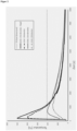
- the manufactured barrier was placed in a space between two fully charged, prismatic NMC 111 cells with 40 Ah. The arrangement corresponds to the illustration in Figure 1 . Thermal runaway of cell 1 was then provoked by penetration with a nail. The temperature development at the front and back of both cells was measured and recorded for a period of 7000 seconds (see Fig. 2 ). The barrier prevented thermal runaway from spreading from cell 1 to cell 2.
Landscapes
- Chemical & Material Sciences (AREA)
- Engineering & Computer Science (AREA)
- Chemical Kinetics & Catalysis (AREA)
- Electrochemistry (AREA)
- General Chemical & Material Sciences (AREA)
- Manufacturing & Machinery (AREA)
- Materials Engineering (AREA)
- Organic Chemistry (AREA)
- Polymers & Plastics (AREA)
- Medicinal Chemistry (AREA)
- Health & Medical Sciences (AREA)
- General Engineering & Computer Science (AREA)
- Physics & Mathematics (AREA)
- Combustion & Propulsion (AREA)
- Thermal Sciences (AREA)
- Mechanical Engineering (AREA)
- Sealing Battery Cases Or Jackets (AREA)
- Battery Mounting, Suspending (AREA)
Description
- Die vorliegende Erfindung betrifft eine Barriere zur Abwendung der Propagation eines thermischen Ereignisses innerhalb eines mehrzelligen Batteriemoduls (sog. "Propagationsbarriere"), die eine hitzeabsorbierende Schutzschicht basierend auf einem Hydrogel und einem verstärkenden Füllmaterial umfasst. Des Weiteren bezieht sich die Erfindung auf ein Batteriemodul, welches die Barriere umfasst und auf die Verwendung der Barriere zur Kompensation von Volumenschwankungen innerhalb eines Batteriemoduls. Außerdem wird auch ein Verfahren zur Herstellung der Propagationsbarriere angegeben.
- Thermische Ereignisse können grundsätzlich in allen Batterietypen vorkommen. Eines der am meisten gefürchteten thermischen Ereignisse ist das thermische Durchgehen einer Batterie (besser bekannt unter dem englischen Begriff "thermal runaway"). Dazu kann es kommen, wenn die Geschwindigkeit, mit der die Batterie Wärme erzeugt, die Geschwindigkeit übersteigt, mit der die Wärme abgeführt werden kann. Wird hierbei eine kritische Temperatur überschritten, kommt es dazu, dass sich der im Inneren der Batterie ablaufende Wärme produzierende Prozess selbst verstärkt und sich die Batterie innerhalb kürzester Zeit auf mehrere hundert Grad Celsius erhitzt. Gleichzeitig kommt es zu einem extremen Druckanstieg in der Zelle, welcher ein explosionsartiges Austreten von Zersetzungsgasen und einen Brand zur Folge haben kann.
- In mehrzelligen Batteriemodulen ist die Gefahr, die von einem solchen thermischen Ereignis ausgeht, potenziert. Der Abstand zwischen den einzelnen Zellen bietet keinen ausreichenden Schutz gegen eine Propagation des thermischen Durchgehens. Aufgrund der hohen Temperatur, die sich bei der vom thermischen Durchgehen betroffenen Zelle einstellt, erhitzen sich auch die angrenzenden Zellen über die kritische Temperatur hinaus. Dementsprechend kann das thermische Durchgehen einer einzigen Zelle leicht zu einer Zerstörung des kompletten Batteriemoduls führen.
- Besonders anfällig für thermisches Durchgehen sind Lithium-Ionen-Batterien. Diese besitzen eine erheblich höhere Energiedichte als andere Batterietypen und können ggf. Zersetzungsgase mit einem großen Anteil an Sauerstoff freisetzen, was zu noch höheren Temperaturen im Fehlerfall führen kann. In Anwendungsfeldern, in denen der Platzbedarf des Batteriemoduls kritisch ist, sind viele Batteriehersteller dazu übergegangen, die Packungsdichte der Lithium-Ionen-Zellen bis auf das Äußerte zu erhöhen. Somit steht nur wenig Bauraum für Barrieren zur Abwendung der Propagation von thermischen Ereignissen zu Verfügung, was in vielen Fällen eine ungenügende thermische Isolierung zwischen den Zellen bewirkt.
- Vor diesem Hintergrund werden im Stand der Technik unterschiedliche Barrierematerialien für Batterien vorgeschlagen.
- Die
WO 2010/017169 A1 beschäftigt sich ebenfalls mit dem Problem des thermischen Durchgehens von mehrzelligen Batteriepacks, insbesondere von Lithiumionen-Batteriepacks, und schlägt Strategien vor, wie die Übertragung eines thermischen Ereignisses von einer Batteriezelle auf eine benachbarte Batteriezelle verhindert werden kann. Hierfür wird eine Propagationsbarriere mit einem Hydrogel als hitzeabsorbierenden Material angegeben. Das Hydrogel wird in einer flexiblen Beutelverpackung oder einem formstabilen Container vorgehalten und in das Batteriemodul eingebracht. Die flexible Beutelverpackung passt sich an die Form der Batteriezellen an, um die Übertragung der Wärme von der Batteriezelle auf das Hydrogel zu gewährleisten. Der Container kann maßangefertigt werden, um ebenfalls einen Kontakt zu der Zelloberfläche herzustellen. Beides ist jedoch verbesserungswürdig. Das Element kann nur begrenzt als Barriere fungieren. In der Ausführungsform, in der das Hydrogel in einer Beutelverpackung vorgehalten wird, fehlt es an einem Abstandshalter zwischen den Zellen, der das thermische Durchgehen einer angrenzenden Zelle überdauern würde. Sobald das Wasser verdampft und das Matrixmaterial des Hydrogels zersetzt ist, können benachbarte Zellen in direkten Kontakt miteinander kommen. In der Ausführungsform, in der das Hydrogel in einem Container vorgehalten wird, sind die Zellen zwar nicht in direktem Kontakt miteinander, jedoch bilden die aus einem Vollmaterial gefertigten Containerwände eine Wärmebrücke, über welche sich das thermische Ereignis nach Verdampfen des im Hydrogel enthaltenen Wassers weiter ausbreiten kann. - Auch die
CN 105 169 613 A empfiehlt die Verwendung von Hydrogel umfassend 0,5-40 Masseteile Hydrogelmaterial und mindestens 50 Masseteile Wasser in Lithiumbatterien. Genauer gesagt wird das Hydrogel hier auf Verpackungselementen der Lithiumbatterie aufgebracht. - Ausgehend von diesem Stand der Technik lag die Aufgabe der vorliegenden Erfindung in der Bereitstellung einer Barriere mit einem formstabilen hitzeabsorbierenden Material, das mindestens genauso effektiv in der Abwendung der Propagation eines thermischen Ereignisses innerhalb eines mehrzelligen Batteriemoduls ist, wie herkömmliche Barrieren. Insbesondere sollte eine Barriere entwickelt werden, die zusätzlich auch Dilatationseffekte von Batteriezellen wirkungsvoll ausgleichen kann. Darüber hinaus sollte ein entsprechendes Batteriemodul angegeben werden. Weiterhin hat sich die vorliegende Erfindung zum Ziel gesetzt, ein Verfahren zur Herstellung einer solchen Barriere anzugeben.
- Diese Aufgabe wird durch die Barriere gemäß Anspruch 1, die Verwendung einer Barriere gemäß Anspruch 11, das Batteriemodul gemäß Anspruch 12 und das Verfahren gemäß Anspruch 14 gelöst.
- Erfindungsgemäß wird eine Barriere zur Abwendung der Propagation eines thermischen Ereignisses innerhalb eines mehrzelligen Batteriemoduls bereitgestellt, umfassend eine hitzeabsorbierende Schutzschicht, die 70,0 - 97,5 Gew.-% eines Hydrogels und 2,5 - 30,0 Gew.-% eines verstärkenden Füllmaterials enthält, wobei das Hydrogel ein Matrixmaterial und Wasser umfasst und das verstärkende Füllmaterial in dem Hydrogel dispergiert ist und wobei das verstärkende Füllmaterial ein partikelförmiges Material ist.
- Durch den hohen Anteil an Hydrogel kann die hitzeabsorbierende Schutzschicht besonders effektiv Wärme aufnehmen und benachbarte Zellen in dem Batteriemodul thermisch voneinander abschirmen. Je höher der Anteil des Hydrogels, desto höher auch die Wassermenge, die enthalten ist und die unter Hitzeentwicklung verdampft und desto besser die Wärmedissipation.
- Unter einem verstärkenden Füllmaterial im Sinne der vorliegenden Erfindung wird ein partikelförmiges Material verstanden. Das partikelförmige Material kann schüttfähig und/oder rieselfähig vorliegen, insbesondere als Pulver oder Granulat. Dementsprechend fällt eine vorgeformte Struktur, beispielsweise eine Trägermatrix in Form einer Gitterstruktur und/oder Wabenstruktur, nicht unter den Begriff "verstärkendes Füllmaterial".
- Die Anwesenheit von mindestens 2,5 Gew.-% eines verstärkenden Füllmaterials gewährleistet die Formstabilität der hitzeabsorbierenden Schutzschicht. Diese Formstabilität drückt sich insbesondere dadurch aus, dass die hitzeabsorbierende Schutzschicht selbsttragend ist. Gleichzeitig sorgt der Maximalanteil von 30 Gew.-% Füllmaterial dafür, dass noch eine gewisse Flexibilität der Schutzschicht erhalten bleibt.
- Zudem kann das verstärkende Füllmaterial die Ausbildung von Wärmebrücken zwischen benachbarten Zellen in dem Batteriemodul verhindern. Durch die Dispergierung liegt das Füllmaterial statistisch verteilt in der hitzeabsorbierenden Schutzschicht vor und kann selbst nach Verdampfen des Wassers und Zersetzen des Matrixmaterials im Falle eines thermischen Ereignisses noch als Isolator zwischen benachbarten Zellen wirken.
- In einer bevorzugten Ausführungsform enthält die hitzeabsorbierende Schutzschicht in der erfindungsgemäßen Barriere 70,0 - 95,0 Gew.-% eines Hydrogels und 5,0 - 30,0 Gew.-% eines verstärkenden Füllmaterials.
- Der Zusatz von 5 bis 30 Gew.-% an verstärkendem Füllmaterial minimiert das Austreten von Wasser aus dem Hydrogel während der thermischen Zyklisierung (Einfrieren/Auftauen) der Barriere. Dadurch eignet sich die Barriere für die Anwendung in Batterien und Batteriemodulen, die im Außenbereich eingesetzt werden und winterlichen Verhältnissen ausgesetzt sind.
- Insbesondere enthält die hitzeabsorbierende Schutzschicht in der erfindungsgemäßen Barriere 80,0 - 92,5 Gew.-% eines Hydrogels und 7,5 - 20,0 Gew.-% eines verstärkenden Füllmaterials.
- Das verstärkende Füllmaterial besteht bevorzugt aus Partikeln mit einem Seitenverhältnis ("aspect ratio") im Bereich von 0,5 bis 10, wobei das Seitenverhältnis gemäß der ISO-Norm 9276-6 gemessen wird. Besonders bevorzugt besteht das verstärkende Füllmaterial aus sphärischen Partikeln.
- In einer Ausführungsform sind die Partikel anorganische Partikel. Vorzugsweise weisen die Partikel eine mittlere Partikelgröße d50 von 1 nm bis 5 mm, bevorzugt von 100 nm bis 5 mm, insbesondere von 1000 nm bis 2 mm auf, wobei die mittlere Partikelgröße d50 gemäß der ISO-Norm 13320-1 gemessen wird.
- Die hitzeabsorbierende Schutzschicht kann in einer wasserdampfundurchlässigen Folie eingewickelt oder eingeschlossen, beispielsweise eingeschweißt, sein. Anders als bei herkömmlichen Propagationsbarrieren ist die Verpackung in einer Folie aber nicht notwendig, um eine ungewollte Ausbreitung des Hydrogels zu verhindern. Die Folie soll die hitzeabsorbierende Schutzschicht lediglich vor langzeitigem Wasserverlust schützen, also dem Diffusionsverlust von Wasser entgegenwirken.
- Die wasserdampfundurchlässige Folie ist bevorzugt eine Polymerfolie, eine Metallfolie oder ein Laminat der vorgenannten Folien, besonders bevorzugt mit einer Foliendicke von weniger als 0,3 mm, insbesondere von weniger als 0,2 mm. Die Polymerfolie kann beispielsweise aus der Gruppe bestehend aus Polyethylen (PE), Polypropylen (PP), Polyvinylidenfluorid (PVDF), Polychlortrifluorethylen (PCTFE), Polyphenylensulfid (PPS), Ethylen-Tetrafluorethylen-Copolymer (ETFE), Polyurethanen (PU), Polyamiden (PA), Polyestern, insbesondere Polyethylenterephthalat (PET), und Kombinationen hiervon ausgewählt sein. Die Metallfolie ist vorzugsweise eine Aluminiumfolie.
- In einer vorteilhaften Ausführungsform besteht das Matrixmaterial zu mindestens 85 Gew.-% aus einem natürlichen Polymer. Das natürliche Polymer basiert bevorzugt auf biogenen Rohstoffen. Unter den Begriff "biogene Rohstoffe" im Sinne der vorliegenden Erfindung fallen organische Rohstoffe, die land- und forstwirtschaftlich erzeugt oder aus Bakterien-, Hefen-, Pilz- Aqua- oder Meereskulturen isoliert worden sind sowie organische Rohstoffe tierischer Herkunft, nämlich solche, die ohnehin als Nebenprodukt bei der Tierschlachtung anfallen und einer Verwertung bedürfen. Ferner sind "biogene Rohstoffe" im Sinne der vorliegenden Erfindung gemäß der DIN EN 13432 biologisch abbaubar. Den biogenen Rohstoffen gegenüber stehen fossile Rohstoffe und Energieträger auf petrochemischer Basis, unter anderem Stoffe, die durch chemische Syntheseverfahren gewonnen worden sind und/oder nicht biologisch abbaubar sind.
- Bevorzugt besteht das Matrixmaterial zu mindestens 85 Gew.-% aus einem natürlichen Polymer ausgewählt aus der Gruppe bestehend aus Alginat, Agar-Agar, Stärke, Stärkederivaten, κ-Carrageenan, i-Carrageenan, Pektin, Gellan, Scleroglucan, und Kombinationen hiervon.
- Obwohl Herkunft und Zusammensetzung der oben genannten Polysaccharide dem Fachmann bekannt sind, wird nachfolgend auf einzelne Polysaccharide näher eingegangen:
Alginat ist die Hauptstrukturkomponente der Zellwände von braunen Makroalgen. Es ist ein lineares Copolymer der Uronsäure β-D-Mannuronat (M) und ihres C-5-Epimers α-L-Guluronat (G), das homopolymere Blöcke aus 1,4-verknüpften aufeinanderfolgenden M-Einheiten (polyM) oder G-Einheiten (polyG) oder Blöcke aus alternierenden M- und G-Einheiten (polyMG) umfasst. Alginat kann in Form seiner Salze, z. B. Alkali- oder Erdalkalimetallsalze, oder in veresterter Form, z. B. in Form eines Alkylesters, z.B. eines Methylesters, vorliegen. - Agar-Agar wird ebenfalls aus den Zellwänden von Algen gewonnen, z.B. aus Blau- oder Rotalgen. Es entspricht im Wesentlichen einer Mischung der Polysaccharide Agarose und Agaropektin, wobei Agarose bevorzugt 60-80 Gew.-% der Mischung ausmacht. Agarose ist ein Polysaccharid aus D-Galactose und 3,6-Anhydro-L-Galactose, die glycosidisch miteinander verbunden sind. Agaropektin ist ein Polysaccharid aus β-1,4 und α-1-3 glycosidisch verknüpfter D-Galactose sowie 3,6-Anhydro-L-Galactose. Etwa jeder zehnte Galactose-Rest ist an O-6 mit Schwefelsäure verestert und enthält zusätzliche Sulfat-Reste. Agar-Agar ist ein ganz besonders bevorzugtes natürlich vorkommendes Geliermittel im Sinne der vorliegenden Erfindung. Grund dafür ist, dass ein auf Agar-Agar basierendes Hydrogel bei Temperaturen unterhalb von etwa 85°C formstabil ist und erst oberhalb dieser Temperatur Wasser abgibt.
- κ-Carrageenan besteht aus sich wiederholenden Monomeren aus D-Galaktose-4-sulfat und 3,6-Anhydro-D-galaktose. i-Carrageenan unterscheidet sich von κ-Carrageenan nur darin, dass die 3,6-Anhydro-D-galaktose-Einheit in C-2-Position eine zusätzliche Sulfat-Gruppe trägt. Beide Carrageenane kommen in der Natur als Grundsubstanz der Zellwände bei einer Vielzahl von Rotalgen vor.
- Gellan ist ein Polysaccharid umfassend eine Wiederholungseinheit, die aus einer Rhamnose-, einer Glucuronsäure- und zwei Glucose-Grundeinheiten, die mit Essigsäure und Glycerinsäure verestert sind, besteht. Es kann beispielsweise durch Fermentation von Kohlenhydraten durch den Bakterienstamm Pseudomonas elodea hergestellt werden.
- Scleroglucan ist ein β-1,3-Glucan das im Durchschnitt an jedem dritten Zucker einen Glucoserest als Seitenkette trägt. Scleroglucan wird bevorzugt aus Pilzkulturen gewonnen.
- Das Matrixmaterial der Hydrogels kann zu mindestens 85 Gew.-%, bevorzugt zu mindestens 95 Gew. %, besonders bevorzugt zu mindestens 99 Gew.-%, aus Calcium-Alginat bestehen.
- Das Matrixmaterial kann weiterhin bis zu 15 Gew.-%, bevorzugt bis zu 5 Gew.-%, insbesondere bis zu 1 Gew.-%, eines Verdickungsmittels umfassen. Durch Hinzufügen eines Verdickungsmittels können die mechanischen Eigenschaften der hitzeabsorbierenden Schutzschicht in einem noch breiteren Bereich eingestellt werden. Insbesondere können Flexibilität bzw. Kompressibilität nach Belieben und mit Blick auf die Anforderungen in der jeweiligen Anwendung angepasst werden. Dies ist zum Beispiel vorteilhaft, um Dilatationseffekte der Batteriezellen, zu denen es während des Lade- und Entladevorgangs und durch Alterung kommen kann, zu kompensieren.
- Das Verdickungsmittel ist bevorzugt ausgewählt aus der Gruppe bestehend aus Cellulosederivaten, insbesondere Hydroxyethylcellulose; Hydroxypropylcellulose; Hydroxypropylmethylcellulose und/oder Carboxycellulose, Guaran, Xanthan-Gummi oder Mischungen hiervon. Auch diese Materialien sind "biogene Rohstoffe" und sind Teil eines nachhaltigen Ansatzes zur Herstellung von Batterien. Insbesondere tragen sie dazu bei, die CO2-Bilanz, die mit dem Produktionsprozess der Barriere verknüpft ist, zu verbessern.
- Das verstärkende Füllmaterial ist vorzugsweise aus der Gruppe bestehend aus Hydroxylapatit, Calciumcarbonat, Calciumsulfat; Aluminiumoxid, Magnesiumoxid, Hydraten der vorgenannten Stoffe sowie Mischungen hiervon ausgewählt. Die vorgenannten Materialien haben eine geringe Wärmeleitfähigkeit und sind in geeigneten Partikelgrößen verfügbar. Für den Fall, dass Hydrate als Füllmaterialien verwendet werden, wird die hitzeabsorbierende Eigenschaft der Schutzschicht noch verstärkt, da auch das Kristallwasser Wärme aufnehmen und verdampfen kann.
- Das Hydrogel kann 5 - 30 Gew.-% Matrixmaterial und 70 - 95 Gew.-% Wasser enthalten oder daraus bestehen. Besonders bevorzugt enthält oder besteht das Hydrogel aus 5 - 20 Gew.-% Matrixmaterial und 80 - 95 Gew.-% Wasser.
- Die hitzeabsorbierende Schutzschicht weist eine Dicke von 0,25 - 10,0 mm, bevorzugt eine Dicke von 1,5 - 3,0 mm, insbesondere eine Dicke von 1,5 bis 2,5 mm, auf. Dadurch nimmt die Barriere möglichst wenig Raum in dem Batteriemodul ein und erfüllt trotzdem noch ihre Funktion, nämlich die Batteriezellen nach Einbau in ein Batteriemodul thermisch voneinander abzuschirmen.
- Um die Kompressibilität weiter anzupassen, können Durchtrittsöffnungen in der der hitzeabsorbierenden Schutzschicht vorgesehen werden. In einem Zustand ohne äußere Krafteinwirkung auf die Propagationsbarriere sind die Durchtrittsöffnungen Aussparungen bzw. Löcher in der Schutzschicht, also Hohlräume, die nicht mit Material gefüllt sind. Bei Krafteinwirkung kann die Materialmischung, aus der die Schutzschicht besteht, in die Hohlräume der Durchtrittsöffnungen verdrängt werden. Dadurch ergibt sich eine hohe Kompressibilität der Schutzschicht im Vergleich zu einem Vollmaterial. Reversible und irreversible Volumenänderungen der in einem Batteriemodul enthaltenen Batteriezellen können kompensiert werden.
- Der volumenmäßige Anteil der Durchtrittsöffnungen an der Schutzschicht beträgt bevorzugt zwischen 1% und 90%, weiter bevorzugt zwischen 8% und 80%, besonders bevorzugt zwischen 10% und 75%, insbesondere zwischen 20% und 60%.
- Jede Durchtrittsöffnung weist bevorzugt eine Querschnittsfläche von 0,025 mm2 - 50,0 mm2, weiter bevorzugt von 0,5 mm2 - 8,0 mm2, insbesondere von 2,0 mm2- 5,0 mm2, auf.
- Die Querschnittsfläche kann - muss aber nicht - für alle Durchtrittsöffnungen identisch sein. Hier ist zu berücksichtigen, dass eine identische Querschnittsfläche aller Durchtrittsöffnungen den Herstellungsprozess womöglich vereinfachen kann.
- Die Durchtrittsöffnungen können Querschnittsformen aufweisen, die ausgewählt sind aus der Gruppe bestehend aus kreisförmig, ellipsenförmig, superellipsenförmig, sternförmig, schlitzförmig, halbmondförmig, rautenförmig, polygonförmig und Kombinationen hiervon. Die Verwendung von nicht kreisförmigen Querschnitten führt zu spezifischen Kraft-Weg- bzw. Kraft-Kompressions-Kurven der Propagationsbarriere. Beispielsweise kann durch Verwendung von sternförmigen Durchtrittsöffnungen eine Kraft-Weg-Kurve realisiert werden, bei der unter sehr geringer Krafteinwirkung ein gewisses Kompressionslevel erreicht wird, dann aber erheblich mehr Kraft nötig ist, um die Barriere weiter zu komprimieren.
- In einer bevorzugten Ausführungsform sind die Durchtrittsöffnungen ungleichmäßig verteilt, insbesondere so, dass in einem ersten Bereich, der näher zum Mittelpunkt der Propagationsbarriere als zu deren Rand ist, eine Flächendichte ρ1 an Durchtrittsöffnungen vorliegt, und in einem zweiten Bereich, der näher zum Rand der Propagationsfolie als zu deren Mittelpunkt ist, eine Flächendichte ρ2 an Durchtrittsöffnungen vorliegt, wobei ρ1 ≠ ρ2 gilt. Generell gilt, dass die Verteilung der Durchtrittsöffnungen in der Schutzschicht an den Aufbau und die Geometrie des Batteriemoduls angepasst sein sollte. Das bedeutet, dass die größere Flächendichte an Durchtrittsöffnungen dort vorliegt, wo die anliegenden Batteriezellen im Betrieb eine größere reversible und irreversible Dilatation aufweisen. Unter Flächendichte ist im Rahmen der vorliegenden Erfindung der Anteil der Querschnittsfläche von Durchtrittsöffnungen bezogen auf ein Flächenelement der Propagationsbarriere zu verstehen.
- Des Weiteren kann der Querschnitt der Durchtrittsöffnungen über die Dicke der Schutzschicht konstant sein oder sich, alternativ, entweder verjüngen oder aufweiten.
- Aus den obigen Ausführungen geht hervor, dass ein weiterer Aspekt der vorliegenden Erfindung die Verwendung der Barriere zur Kompensation von Volumenschwankungen innerhalb eines Batteriemoduls ist. Die Volumenschwankungen können auf reversibel Dilatationseffekte bei Lade- und Entladevorgängen zurückzuführen sein oder auf irreversible Dilatationseffekte durch Alterung der Batteriezellen.
- Ebenso wird durch die Erfindung ein Batteriemodul umfassend mehrere Batteriezellen und mindestens eine der oben beschriebenen Barrieren bereitgestellt. Die Barriere ist in dem Batteriemodul bevorzugt zwischen zwei benachbarten Batteriezellen angeordnet.
- Da Lithium-Ionen-Zellen besonders anfällig für thermisches Durchgehen sind, ist es weiterhin vorteilhaft, wenn die Batteriezellen in dem Batteriemodul Lithium-Ionen-Zellen sind.
- Zuletzt gibt die Erfindung auch ein Verfahren zur Herstellung der erfindungsgemäßen Barriere an. Bei dem Verfahren wird zunächst eine hitzeabsorbierende Schutzschicht hergestellt, wobei die Herstellung der hitzeabsorbierenden Schutzschicht die folgenden Schritte i) - iii) umfasst:
- i) Natrium-Alginat Pulver, ein verstärkendes Füllmaterial und Wasser werden gemischt, so dass eine dickflüssige Masse entsteht,
- ii) die Masse wird auf eine ebene Fläche oder in eine Gießform mit planarem Boden gegossen, und
- iii) die gegossene Masse wird mit einer calciumionenhaltigen Lösung benetzt oder in eine calciumionenhaltige Lösung getaucht.
- Anschließend kann die ausgehärtete Masse abgetupft und in eine wasserdampfundurchlässige Folie eingewickelt und/oder eingeschweißt werden. Dieses Herstellungsverfahren ist einfach und benötigt keine kostenintensiven Hilfsmittel. Darüber hinaus ist das Verfahren mit einem geringen CO2-Fußabdruck verbunden.
- Bevorzugte Ausführungsformen der Erfindung werden unter Bezugnahme auf die Figuren und das nachfolgende Beispiel näher erläutert, ohne die Erfindung darauf beschränken zu wollen. Insbesondere beschreibt das nachfolgende Beispiel nur einen Herstellungsweg für die erfindungsgemäßen Barrieren. Es ist davon auszugehen, dass eine industrielle Fertigung der Barrieren ebenfalls durch Extrusion möglich ist.
-
Figur 1 zeigt die Anordnung einer erfindungsgemäßen Barriere 3 in einem Batterie(-Test)-Modul umfassend zwei Batteriezellen 1 und 2. Bei 5a und 5b handelt es sich um eine thermische Isolation, welche nach dem proaktiven Auslösen des thermischen Ereignisses verhindert, dass ein Teil der freiwerdenden thermischen Energie von den Spannplatten 6a und 6b, die eine gewissen Wärmekapazität aufweisen, aufgenommen wird. Dadurch werden Messfehler vermieden. Die Spannplatten sorgen für den mechanischen Zusammenhalt des Moduls. Die Messstellen, an denen eine Temperaturmessung erfolgt, liegen auf Vorderseite und Rückseite jeder Zelle. -
Figur 2 zeigt den Temperaturverlauf der Zellen 1 und 2 nach Nagelpenetration von Zelle 1. Aus dem Temperaturverlauf kann abgeleitet werden, dass die erfindungsgemäße Barriere 3 die Zelle 2 erfolgreich thermisch abschirmt. Dadurch wird verhindert, dass Zelle 2 die kritische Temperatur erreicht. - 80 Gew.-% Wasser, 15 Gew.-% Natrium-Alginat und 5 Gew.-% Füllmaterial (Calciumcarbonat) werden für etwa 3 Minuten gemischt. Die resultierende Mischung wird in einer flachen und offenen Form mit einer Dicke von etwa 2,3 mm aufgetragen. Die 2,3 mm dicke Mischung wird mit der Form für 30 Sekunden in eine wässrige CaCl2-Lösung (5 Gew.-%) getaucht. Dadurch entsteht eine hitzeabsorbierende Schutzschicht umfassend ein flexibles, homogenes Hydrogel mit einer Dicke von 2,6 mm. Im Vergleich zu den Abmessungen der Form, in welcher die Mischung aufgetragen wurde, weist die hitzeabsorbierende Schutzschicht sowohl in der Länge als auch in der Breite eine Schrumpfung von etwa 5% auf. Die Schutzschicht enthält etwa 80 Gew.-% Wasser.
- Zuletzt wird die Schutzschicht in eine wasserdampfundurchlässige Folie (Foliendicke 0,15 mm) eingeschweißt.
- Die hergestellte Barriere wurde in einen Zwischenraum zwischen zwei vollgeladenen, prismatischen NMC 111-Zellen mit 40 Ah platziert. Die Anordnung entspricht der Illustration in
Figur 1 . Anschließend wurde das thermische Durchgehen der Zelle 1 durch Penetration mit einem Nagel provoziert. Die Temperaturentwicklung an Vorder- und Rückseite beider Zellen wurde für eine Dauer von 7000 Sekunden gemessen und aufgezeichnet (sieheFig. 2 ). Die Barriere verhinderte das Überspringen des thermischen Durchgehens von Zelle 1 auf die Zelle 2.
Claims (14)
- Barriere zur Abwendung der Propagation eines thermischen Ereignisses innerhalb eines mehrzelligen Batteriemoduls, umfassendeine hitzeabsorbierende Schutzschicht, die 70,0 - 97,5 Gew.-% eines Hydrogels und 2,5 - 30,0 Gew.-% eines verstärkenden Füllmaterials enthält,wobei das Hydrogel ein Matrixmaterial und Wasser umfasst und das verstärkende Füllmaterial in dem Hydrogel dispergiert ist und wobei das verstärkende Füllmaterial ein partikelförmiges Material ist.
- Barriere nach Anspruch 1, wobei die Schutzschicht in einer wasserdampfundurchlässigen Folie eingeschlossen ist, wobei die wasserdampfundurchlässige Folie bevorzugt eine Polymerfolie, eine Metallfolie oder ein Laminat der vorgenannten Folien ist, wobei die Polymerfolie weiter bevorzugt ausgewählt ist aus der Gruppe bestehend aus Polyethylen (PE), Polypropylen (PP), Polyvinylidenfluorid (PVDF), Polychlortrifluorethylen (PCTFE), Polyphenylensulfid (PPS), Ethylen-Tetrafluorethylen-Copolymer (ETFE), Polyurethanen (PU), Polyamiden (PA), Polyestern, insbesondere Polyethylenterephthalat (PET), und Kombinationen hiervon und wobei die Metallfolie weiter bevorzugt eine Aluminiumfolie ist.
- Barriere nach Anspruch 1 oder 2, wobei das Matrixmaterial zu mindestens 85 Gew.-% aus einem natürlichen Polymer besteht, wobei das natürliche Polymer bevorzugt ausgewählt ist aus der Gruppe bestehend aus Alginat, Agar-Agar, Stärke, Stärkederivaten, κ-Carrageenan, i-Carrageenan, Pektin, Gellan, Scleroglucan, und Kombinationen hiervon.
- Barriere nach einem der vorhergehenden Ansprüche, wobei das Matrixmaterial zu mindestens 85 Gew.-%, bevorzugt zu mindestens 95 Gew.-%, besonderes bevorzugt zu mindestens 99 Gew.-%, aus Calcium-Alginat besteht.
- Barriere nach einem der vorhergehenden Ansprüche, wobei das Matrixmaterial weiterhin bis zu 15 Gew.-% eines Verdickungsmittels umfasst, wobei das Verdickungsmittel bevorzugt ausgewählt ist aus der Gruppe bestehend aus Cellulosederivaten, insbesondere Hydroxyethylcellulose; Hydroxypropylcellulose; Hydroxypropylmethylcellulose und/oder Carboxycellulose, Guaran, Xanthan-Gummi oder Mischungen hiervon.
- Barriere nach einem der vorhergehenden Ansprüche, wobei das verstärkende Füllmaterial ausgewählt ist aus der Gruppe bestehend aus Hydroxylapatit, Calciumcarbonat, Calciumsulfat; Aluminiumoxid, Magnesiumoxid, Hydraten der vorgenannten Stoffe sowie Mischungen hiervon.
- Barriere nach einem der vorhergehenden Ansprüche, wobei das Hydrogel 5 - 30 Gew.-% des Matrixmaterials und 70 - 95 Gew.-% Wasser enthält.
- Barriere nach einem der vorhergehenden Ansprüche, wobei die Schutzschicht eine Dicke von 0,25 - 10,0 mm, bevorzugt eine Dicke von 1,5 - 3,0 mm, aufweist.
- Barriere nach einem der vorhergehenden Ansprüche, wobei die hitzeabsorbierende Schutzschicht Durchtrittsöffnungen aufweist, wobei der volumenmäßige Anteil der Durchtrittsöffnungen an der Schutzschicht bevorzugt zwischen 1% und 90%, weiter bevorzugt zwischen 8% und 80%, besonders bevorzugt zwischen 10% und 75%, insbesondere zwischen 20% und 60%, beträgt.
- Barriere nach einem der vorhergehenden Ansprüche, wobei die hitzeabsorbierende Schutzschicht Durchtrittsöffnungen aufweist, wobei jede Durchtrittsöffnung bevorzugt eine Querschnittsfläche von 0,025 mm2 - 50,0 mm2, weiter bevorzugt von 0,5 mm2 - 8,0 mm2, insbesondere von 2,0 mm2 - 5,0 mm2, aufweist.
- Verwendung einer Barriere nach einem der Ansprüche 9 und 10 zur Kompensation von Volumenschwankungen innerhalb eines Batteriemoduls.
- Batteriemodul umfassend mehrere Batteriezellen und mindestens eine Barriere nach einem der Ansprüche 1 bis 10, wobei die Barriere zwischen zwei benachbarten Batteriezellen angeordnet ist.
- Batteriemodul gemäß Anspruch 12, wobei die Batteriezellen Lithium-Ionen-Zellen sind.
- Verfahren zur Herstellung einer Barriere nach einem der Ansprüche 1 bis 10, bei dem eine hitzeabsorbierende Schutzschicht hergestellt wird, indemi) Natrium-Alginat Pulver, ein verstärkendes Füllmaterial und Wasser gemischt werden, so dass eine dickflüssige Masse entsteht,ii) die Masse auf eine ebene Fläche oder in eine Gießform mit planarem Boden gegossen wird, undiii) die gegossene Masse mit einer calciumionenhaltigen Lösung benetzt oder in eine calciumionenhaltige Lösung getaucht wird.
Applications Claiming Priority (2)
| Application Number | Priority Date | Filing Date | Title |
|---|---|---|---|
| DE102021131311.2A DE102021131311A1 (de) | 2021-11-29 | 2021-11-29 | Propagationsbarriere mit verstärkendem Füllmaterial und Verfahren zu deren Herstellung |
| PCT/EP2022/083528 WO2023094666A1 (de) | 2021-11-29 | 2022-11-28 | Propagationsbarriere mit verstärkendem füllmaterial und verfahren zu deren herstellung |
Publications (3)
| Publication Number | Publication Date |
|---|---|
| EP4229704A1 EP4229704A1 (de) | 2023-08-23 |
| EP4229704C0 EP4229704C0 (de) | 2025-04-23 |
| EP4229704B1 true EP4229704B1 (de) | 2025-04-23 |
Family
ID=84519411
Family Applications (1)
| Application Number | Title | Priority Date | Filing Date |
|---|---|---|---|
| EP22822959.7A Active EP4229704B1 (de) | 2021-11-29 | 2022-11-28 | Propagationsbarriere mit verstärkendem füllmaterial und verfahren zu deren herstellung |
Country Status (7)
| Country | Link |
|---|---|
| US (1) | US20240021918A1 (de) |
| EP (1) | EP4229704B1 (de) |
| JP (1) | JP7642828B2 (de) |
| KR (1) | KR20230110785A (de) |
| CN (1) | CN116745973A (de) |
| DE (1) | DE102021131311A1 (de) |
| WO (1) | WO2023094666A1 (de) |
Families Citing this family (3)
| Publication number | Priority date | Publication date | Assignee | Title |
|---|---|---|---|---|
| CN119921021A (zh) * | 2023-10-30 | 2025-05-02 | 比亚迪股份有限公司 | 一种电池组、电池包及用电系统 |
| CN118448788A (zh) * | 2024-05-30 | 2024-08-06 | 中国科学院声学研究所 | 高倍率锂铁一次电池、单层电池模组和动力模组 |
| CN120073147A (zh) * | 2025-04-24 | 2025-05-30 | 涿州市柯林电子产品有限公司 | 一种快速充电电池模块 |
Family Cites Families (9)
| Publication number | Priority date | Publication date | Assignee | Title |
|---|---|---|---|---|
| ATE361124T1 (de) * | 2003-07-23 | 2007-05-15 | Basf Ag | Mischung zur brandüberwachung und verfahren |
| US20100028758A1 (en) | 2008-08-04 | 2010-02-04 | Eaves Stephen S | Suppression of battery thermal runaway |
| JP4900534B2 (ja) * | 2009-02-24 | 2012-03-21 | パナソニック株式会社 | 電池モジュールとそれを用いた電池モジュール集合体 |
| JP5395765B2 (ja) * | 2010-08-25 | 2014-01-22 | 株式会社日立製作所 | 冷却材を備える電池、並びに冷却材を備える組電池 |
| CN105169613A (zh) * | 2015-08-13 | 2015-12-23 | 中国民用航空总局第二研究所 | 锂电池及其包装件燃烧处理用水凝胶 |
| CN105140427B (zh) * | 2015-08-13 | 2019-01-08 | 中国民用航空总局第二研究所 | 一种预防锂电池及其包装件燃烧用材料及制备方法 |
| CN106935933B (zh) * | 2017-04-12 | 2019-04-05 | 厦门金龙联合汽车工业有限公司 | 一种用于增强电池模组散热的水凝胶的制备工艺 |
| EP3627030A4 (de) | 2017-05-15 | 2020-04-15 | Panasonic Intellectual Property Management Co., Ltd. | Wärmedämmungsmaterial und wärmedämmungsstruktur damit |
| DE102021002378A1 (de) | 2021-05-05 | 2021-12-02 | Daimler Ag | Elektrischer Energiespeicher |
-
2021
- 2021-11-29 DE DE102021131311.2A patent/DE102021131311A1/de active Pending
-
2022
- 2022-11-28 US US18/256,873 patent/US20240021918A1/en active Pending
- 2022-11-28 JP JP2023540559A patent/JP7642828B2/ja active Active
- 2022-11-28 KR KR1020237021268A patent/KR20230110785A/ko not_active Ceased
- 2022-11-28 CN CN202280009239.8A patent/CN116745973A/zh active Pending
- 2022-11-28 WO PCT/EP2022/083528 patent/WO2023094666A1/de not_active Ceased
- 2022-11-28 EP EP22822959.7A patent/EP4229704B1/de active Active
Also Published As
| Publication number | Publication date |
|---|---|
| JP2024502967A (ja) | 2024-01-24 |
| WO2023094666A1 (de) | 2023-06-01 |
| EP4229704A1 (de) | 2023-08-23 |
| CN116745973A (zh) | 2023-09-12 |
| DE102021131311A1 (de) | 2023-06-01 |
| JP7642828B2 (ja) | 2025-03-10 |
| US20240021918A1 (en) | 2024-01-18 |
| EP4229704C0 (de) | 2025-04-23 |
| KR20230110785A (ko) | 2023-07-25 |
Similar Documents
| Publication | Publication Date | Title |
|---|---|---|
| EP4229704B1 (de) | Propagationsbarriere mit verstärkendem füllmaterial und verfahren zu deren herstellung | |
| WO2021239378A1 (de) | Propagationsbarriere für batterien | |
| EP2745348B1 (de) | Wärmeableiter und elektrischer energiespeicher | |
| DE1704531A1 (de) | Verfahren zur Herstellung von spezifisch leichten Koerpern | |
| DE1952678A1 (de) | Elektrisches Widerstandselement und Verfahren zu dessen Herstellung | |
| EP1229904A1 (de) | Verfahren zum herstellen eines stärke enthaltenden formkörpers | |
| EP2938486B1 (de) | Verbundglas | |
| DE19525024A1 (de) | Sandwichpaneel | |
| DE102007051830A1 (de) | Wärmedämmmaterialaufweisender Baustein sowie Verfahren zu seiner Herstellung | |
| DE2720250A1 (de) | Separator fuer bleiakkumulatoren | |
| DE102021002378A1 (de) | Elektrischer Energiespeicher | |
| DE102016223057B4 (de) | Thermisch isolierendes flächiges Bauteil mit geringer Bauteildicke, insbesondere als Funktionsraumverkleidung eines Kraftfahrzeugs | |
| DE4010907A1 (de) | Elektrochemische zelle | |
| DE202010001167U1 (de) | Plattenförmige Isolationslage für eine Wand sowie plattenförmiges Wandelement | |
| DE102021124581A1 (de) | Elektrische energiespeichereinrichtung, verfahren zu deren herstellung und kraftfahrzeug mit einer solchen energiespeichereinrichtung | |
| WO1982000040A1 (en) | Insulation for protection against fire comprising a granular mass of which the structure changes endothermally when a maximum temperature allowed is reached | |
| DE3603196A1 (de) | Verfahren zur herstellung eines bleiakkumulators mit gel-elektrolyten | |
| DE102013113880B4 (de) | Vorrichtung und Verfahren zum Transport von galvanischen Zellen | |
| WO2021116153A2 (de) | Flächenmaterial, sandwichmaterial, elektrochemische speichereinheit und verfahren zur herstellung eines flächenmaterials | |
| DE102018120957A1 (de) | Verfahren zum Herstellen von Feuerschutzabschlusselementen mit und ohne Verglasung sowie Feuerschutzabschlusselement und Feuerschutzabschlusselementserie | |
| DE3411296C2 (de) | Wärmedämmittel zum Einbau in Hohlprofile von Brandschutzkonstruktionen | |
| DE2948985C2 (de) | Verfahren zum Schutze elektrochemischer Zellen, Halterung zur Durchführung des Verfahrens und elektrochemische Sicherheitszelle | |
| DE102010062868A1 (de) | Batterie | |
| DE102008052329A1 (de) | Tresor, insbesondere Brandschutzschrank und Verfahren zu seiner Herstellung | |
| DE102022120726A1 (de) | Energiespeicher für ein Kraftfahrzeug, Kraftfahrzeug und Verfahren zum Herstellen eines Energiespeichers |
Legal Events
| Date | Code | Title | Description |
|---|---|---|---|
| STAA | Information on the status of an ep patent application or granted ep patent |
Free format text: STATUS: UNKNOWN |
|
| STAA | Information on the status of an ep patent application or granted ep patent |
Free format text: STATUS: THE INTERNATIONAL PUBLICATION HAS BEEN MADE |
|
| PUAI | Public reference made under article 153(3) epc to a published international application that has entered the european phase |
Free format text: ORIGINAL CODE: 0009012 |
|
| STAA | Information on the status of an ep patent application or granted ep patent |
Free format text: STATUS: REQUEST FOR EXAMINATION WAS MADE |
|
| 17P | Request for examination filed |
Effective date: 20230516 |
|
| AK | Designated contracting states |
Kind code of ref document: A1 Designated state(s): AL AT BE BG CH CY CZ DE DK EE ES FI FR GB GR HR HU IE IS IT LI LT LU LV MC ME MK MT NL NO PL PT RO RS SE SI SK SM TR |
|
| RIN1 | Information on inventor provided before grant (corrected) |
Inventor name: BOESE, OLAF Inventor name: BECHER, DANIEL Inventor name: BAUSCH, BRUNO |
|
| GRAP | Despatch of communication of intention to grant a patent |
Free format text: ORIGINAL CODE: EPIDOSNIGR1 |
|
| STAA | Information on the status of an ep patent application or granted ep patent |
Free format text: STATUS: GRANT OF PATENT IS INTENDED |
|
| DAV | Request for validation of the european patent (deleted) | ||
| DAX | Request for extension of the european patent (deleted) | ||
| INTG | Intention to grant announced |
Effective date: 20241204 |
|
| GRAS | Grant fee paid |
Free format text: ORIGINAL CODE: EPIDOSNIGR3 |
|
| GRAA | (expected) grant |
Free format text: ORIGINAL CODE: 0009210 |
|
| STAA | Information on the status of an ep patent application or granted ep patent |
Free format text: STATUS: THE PATENT HAS BEEN GRANTED |
|
| AK | Designated contracting states |
Kind code of ref document: B1 Designated state(s): AL AT BE BG CH CY CZ DE DK EE ES FI FR GB GR HR HU IE IS IT LI LT LU LV MC ME MK MT NL NO PL PT RO RS SE SI SK SM TR |
|
| REG | Reference to a national code |
Ref country code: GB Ref legal event code: FG4D Free format text: NOT ENGLISH |
|
| REG | Reference to a national code |
Ref country code: CH Ref legal event code: EP |
|
| REG | Reference to a national code |
Ref country code: DE Ref legal event code: R096 Ref document number: 502022003709 Country of ref document: DE |
|
| REG | Reference to a national code |
Ref country code: IE Ref legal event code: FG4D Free format text: LANGUAGE OF EP DOCUMENT: GERMAN |
|
| U01 | Request for unitary effect filed |
Effective date: 20250520 |
|
| U07 | Unitary effect registered |
Designated state(s): AT BE BG DE DK EE FI FR IT LT LU LV MT NL PT RO SE SI Effective date: 20250527 |
|
| PG25 | Lapsed in a contracting state [announced via postgrant information from national office to epo] |
Ref country code: ES Free format text: LAPSE BECAUSE OF FAILURE TO SUBMIT A TRANSLATION OF THE DESCRIPTION OR TO PAY THE FEE WITHIN THE PRESCRIBED TIME-LIMIT Effective date: 20250423 |
|
| PG25 | Lapsed in a contracting state [announced via postgrant information from national office to epo] |
Ref country code: GR Free format text: LAPSE BECAUSE OF FAILURE TO SUBMIT A TRANSLATION OF THE DESCRIPTION OR TO PAY THE FEE WITHIN THE PRESCRIBED TIME-LIMIT Effective date: 20250724 Ref country code: NO Free format text: LAPSE BECAUSE OF FAILURE TO SUBMIT A TRANSLATION OF THE DESCRIPTION OR TO PAY THE FEE WITHIN THE PRESCRIBED TIME-LIMIT Effective date: 20250723 |
|
| PG25 | Lapsed in a contracting state [announced via postgrant information from national office to epo] |
Ref country code: PL Free format text: LAPSE BECAUSE OF FAILURE TO SUBMIT A TRANSLATION OF THE DESCRIPTION OR TO PAY THE FEE WITHIN THE PRESCRIBED TIME-LIMIT Effective date: 20250423 |
|
| PG25 | Lapsed in a contracting state [announced via postgrant information from national office to epo] |
Ref country code: HR Free format text: LAPSE BECAUSE OF FAILURE TO SUBMIT A TRANSLATION OF THE DESCRIPTION OR TO PAY THE FEE WITHIN THE PRESCRIBED TIME-LIMIT Effective date: 20250423 |
|
| PG25 | Lapsed in a contracting state [announced via postgrant information from national office to epo] |
Ref country code: RS Free format text: LAPSE BECAUSE OF FAILURE TO SUBMIT A TRANSLATION OF THE DESCRIPTION OR TO PAY THE FEE WITHIN THE PRESCRIBED TIME-LIMIT Effective date: 20250723 |
|
| PG25 | Lapsed in a contracting state [announced via postgrant information from national office to epo] |
Ref country code: IS Free format text: LAPSE BECAUSE OF FAILURE TO SUBMIT A TRANSLATION OF THE DESCRIPTION OR TO PAY THE FEE WITHIN THE PRESCRIBED TIME-LIMIT Effective date: 20250823 |
|
| U20 | Renewal fee for the european patent with unitary effect paid |
Year of fee payment: 4 Effective date: 20251112 |
|
| PG25 | Lapsed in a contracting state [announced via postgrant information from national office to epo] |
Ref country code: SM Free format text: LAPSE BECAUSE OF FAILURE TO SUBMIT A TRANSLATION OF THE DESCRIPTION OR TO PAY THE FEE WITHIN THE PRESCRIBED TIME-LIMIT Effective date: 20250423 |
|
| PG25 | Lapsed in a contracting state [announced via postgrant information from national office to epo] |
Ref country code: CZ Free format text: LAPSE BECAUSE OF FAILURE TO SUBMIT A TRANSLATION OF THE DESCRIPTION OR TO PAY THE FEE WITHIN THE PRESCRIBED TIME-LIMIT Effective date: 20250423 |
|
| PG25 | Lapsed in a contracting state [announced via postgrant information from national office to epo] |
Ref country code: SK Free format text: LAPSE BECAUSE OF FAILURE TO SUBMIT A TRANSLATION OF THE DESCRIPTION OR TO PAY THE FEE WITHIN THE PRESCRIBED TIME-LIMIT Effective date: 20250423 |