EP4229366B1 - Verfahren zur verifikation eines clamp-on-ultraschall-messgeräts - Google Patents
Verfahren zur verifikation eines clamp-on-ultraschall-messgeräts Download PDFInfo
- Publication number
- EP4229366B1 EP4229366B1 EP21777676.4A EP21777676A EP4229366B1 EP 4229366 B1 EP4229366 B1 EP 4229366B1 EP 21777676 A EP21777676 A EP 21777676A EP 4229366 B1 EP4229366 B1 EP 4229366B1
- Authority
- EP
- European Patent Office
- Prior art keywords
- ultrasonic
- measuring
- verification
- signal
- variable
- Prior art date
- Legal status (The legal status is an assumption and is not a legal conclusion. Google has not performed a legal analysis and makes no representation as to the accuracy of the status listed.)
- Active
Links
Images

Classifications
-
- G—PHYSICS
- G01—MEASURING; TESTING
- G01F—MEASURING VOLUME, VOLUME FLOW, MASS FLOW OR LIQUID LEVEL; METERING BY VOLUME
- G01F1/00—Measuring the volume flow or mass flow of fluid or fluent solid material wherein the fluid passes through a meter in a continuous flow
- G01F1/66—Measuring the volume flow or mass flow of fluid or fluent solid material wherein the fluid passes through a meter in a continuous flow by measuring frequency, phase shift or propagation time of electromagnetic or other waves, e.g. using ultrasonic flowmeters
- G01F1/667—Arrangements of transducers for ultrasonic flowmeters; Circuits for operating ultrasonic flowmeters
-
- G—PHYSICS
- G01—MEASURING; TESTING
- G01F—MEASURING VOLUME, VOLUME FLOW, MASS FLOW OR LIQUID LEVEL; METERING BY VOLUME
- G01F25/00—Testing or calibration of apparatus for measuring volume, volume flow or liquid level or for metering by volume
- G01F25/10—Testing or calibration of apparatus for measuring volume, volume flow or liquid level or for metering by volume of flowmeters
-
- G—PHYSICS
- G01—MEASURING; TESTING
- G01F—MEASURING VOLUME, VOLUME FLOW, MASS FLOW OR LIQUID LEVEL; METERING BY VOLUME
- G01F1/00—Measuring the volume flow or mass flow of fluid or fluent solid material wherein the fluid passes through a meter in a continuous flow
- G01F1/66—Measuring the volume flow or mass flow of fluid or fluent solid material wherein the fluid passes through a meter in a continuous flow by measuring frequency, phase shift or propagation time of electromagnetic or other waves, e.g. using ultrasonic flowmeters
Definitions
- the invention relates to a method for verifying a clamp-on ultrasonic measuring device in measurement and automation technology in order to determine a condition of the measuring device.
- the EP2607864B1 describes a method for in-line testing of a flowmeter in which a calibrated clamp-on ultrasonic measuring device is arranged in series with a flowmeter to be calibrated.
- the clamp-on ultrasonic measuring device is attached to a standard measuring section and measurement results of measured quantities are evaluated.
- the verification is time-consuming because the measured values must first be transferred to an evaluation device in order to then start the actual analysis.
- the object of the invention is to propose a simple and robust verification of a clamp-on ultrasonic measuring device.
- the object is achieved by a method according to independent claim 1 and by a clamp-on ultrasonic measuring device according to independent claim 6.
- a measuring tube can be empty, partially filled, or completely filled with a liquid.
- a measuring block or measuring rod can be used to easily check whether the set values are being met.
- the measuring section is made of at least one of the following materials: Plastic, metal.
- the measuring section and the ultrasonic transducers can be matched to each other. This can, for example, reduce transmission losses due to interface reflections.
- the verification result comprises a history of measured values with respect to a specification variable.
- the verification result includes a prediction regarding a minimum operating time until a target state is left.
- Fig. 1 describes a sequence of an exemplary method 100 according to the invention, in which in a first method step 101 the clamp-on ultrasonic measuring device (1) is mounted on a standard measuring section 40, which standard measuring section can be formed, for example, by a measuring tube 41, a measuring block 42 or a measuring rod 43, see Figs. 4 b) to c) .
- a verification mode is activated. For example, parameters of a last-used measuring point can be saved so that the clamp-on ultrasonic measuring device can be easily reconfigured for this measuring point in the event of a positive verification result.
- a third method step 103 at least one ultrasonic transducer 10 of the clamp-on ultrasonic measuring device is caused to emit at least one ultrasonic signal and at least one ultrasonic transducer is caused to receive the at least one ultrasonic signal.
- a fourth method step 104 the received ultrasonic signal is evaluated by the electronic measuring/operating circuit in order to determine at least one measured value of at least one verification variable of the ultrasonic signal.
- the expert is not limited to this list and can also use other verification parameters.
- a check is then made to determine whether at least one measured value lies within a target range.
- a check is made to determine whether all measured values lie within the corresponding target ranges. This involves accessing at least one specification value stored in a memory/storage unit of the electronic measuring/operating circuit.
- a verification result is output in a fifth method step 105.
- the verification result can, for example, indicate whether the clamp-on ultrasonic measuring device can be used further or not.
- a minimum operating time of the clamp-on ultrasonic measuring device can be determined by an extended evaluation of the at least one measured value, so that a new verification of the clamp-on ultrasonic measuring device can be planned in advance.
- the extended evaluation can, for example, be based on distances between the measured values and limit values of the associated target ranges.
- a verification result can, for example, be determined using a trained neural network, wherein training of the network is carried out using Input of known measured values of verification quantities as well as the associated condition/status of the clamp-on ultrasonic measuring device is possible.
- a sixth method step 106 the verification mode is terminated and, if the result is positive, the clamp-on ultrasonic measuring device is prepared for reuse at a measuring point.
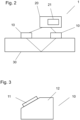
- Fig. 2 1 outlines an exemplary clamp-on ultrasonic measuring device 1 according to the invention with two ultrasonic transducers 10 mounted on the outside of a measuring tube 30, as well as an electronic measuring/operating circuit 20 for operating the ultrasonic transducers and for providing measured values of at least one property of a medium located in the measuring tube.
- the medium property can, for example, be one of the following measured variables: sound velocity, flow velocity, volume flow, and others.
- the electronic measuring/operating circuit has a memory unit 21 in which at least one specification value is stored so that the method according to the invention can be carried out.
- clamp-on ultrasonic measuring devices The functionality of clamp-on ultrasonic measuring devices is known to those skilled in the art.
- Fig. 3 shows an exemplary ultrasonic transducer 10, which has a transducer element 11, in particular a piezo element, which is arranged on a coupling element/ultrasound transmitter 12.
- the coupling element/ultrasound transmitter is contacted with the measuring tube 30 via a side facing away from the transducer element and is configured to transmit ultrasonic signals between the transducer element and the measuring tube and vice versa.
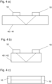
- Fig. 4 b) to c) outline exemplary standard measuring sections 40 by means of which the clamp-on ultrasonic measuring device and in particular the ultrasonic transducers of the clamp-on ultrasonic measuring device can be verified in accordance with the method according to the invention.
- Fig. 4 a shows a standard measuring section not according to the invention with a measuring tube 41 to which the ultrasonic transducers 10 are attached.
- the arrangement can be be designed such that an ultrasonic signal is simply reflected on a wall of the measuring tube 41 on a side of the measuring tube opposite the ultrasonic transducer. Since the measuring tube is used exclusively for verification purposes, it retains its properties and can therefore be used repeatedly for verification.
- the measuring tube can be at least partially filled with a liquid medium for verification.
- Ultrasonic signal reflections can be used.
- Fig. 4 b shows a standard measuring section with a measuring block 42.
- ultrasonic signal reflection occurs primarily at interfaces between the surroundings of the measuring block and the measuring block. This results in a clearer and less noisy ultrasonic signal for a receiving ultrasonic transducer.
- Fig. 4 c sketches a standard measuring section with a measuring rod 43, with the ultrasonic transducers arranged at opposite ends of the measuring rod.
- the ultrasonic signal is not reflected, but is transmitted directly via the measuring rod, i.e., without deflection between the ultrasonic transducers.
Landscapes
- Physics & Mathematics (AREA)
- Fluid Mechanics (AREA)
- General Physics & Mathematics (AREA)
- Electromagnetism (AREA)
- Measuring Volume Flow (AREA)
- Investigating Or Analyzing Materials By The Use Of Ultrasonic Waves (AREA)
- Ultra Sonic Daignosis Equipment (AREA)
Description
- Die Erfindung betrifft ein Verfahren zur Verifikation eines Clamp-On-Ultraschall-Messgeräts der Mess- und Automatisierungstechnik, um einen Zustand des Messgeräts festzustellen.
- Bei Clamp-On-Ultraschall-Messgeräten, wie in der
DE102018133476A1 gezeigt, verändern sich im Laufe des Betriebs wie bei allen anderen Messgeräten auch Eigenschaften des Messgeräts an sich. Dies hat negative Eigenschaften auf eine Messleistung von solchen Messgeräten, weshalb die Messgeräte von Zeit zu Zeit eine Zustandsüberprüfung durchlaufen. - Die
EP2607864B1 beschreibt ein Verfahren zur In-Line-Überprüfung eines Durchflussmessgeräts, bei welchem ein kalibriertes Clamp-On-Ultraschall-Messgerät in Reihe zu einem zu kalibrierenden Durchflussmessgerät angeordnet wird. -
DE 10 2015 106 897 A1 beschreibt auch Verfahren zur Überprüfung eines Ultraschall-Durchflussmessers auf der Grundlage der Laufzeitdifferenz. - Für eine Zustandsüberprüfung wird das Clamp-On-Ultraschall-Messgerät an eine Norm-Messstrecke angebracht und Messergebnisse von Messgrößen werden ausgewertet.
- Dabei wird geprüft, ob die Messwerte innerhalb eines Gültigkeitsbereichs liegen.
- Die Überprüfung ist dabei zeitaufwändig, da die Messwerte zunächst auf ein Auswertegerät übertragen werden müssen, um dann die eigentliche Analyse zu starten.
- Aufgabe der Erfindung ist es, eine einfache und robuste Verifikation eines Clamp-On-Ultraschall-Messgeräts vorzuschlagen.
- Die Aufgabe wird gelöst durch ein Verfahren gemäß dem unabhängigen Anspruch 1 sowie durch ein Clamp-On-Ultraschall-Messgerät gemäß dem unabhängigen Anspruch 6.
- Bei einem erfindungsgemäßen Verfahren zur Verifikation eines Clamp-On-Ultraschall-Messgeräts,
wobei das Messgerät umfasst: - zumindest zwei Ultraschallwandler eingerichtet zum Aussenden und Empfangen von Ultraschallsignalen,
- eine elektronische Mess-/Betriebsschaltung eingerichtet zum Betreiben des mindestens einen Ultraschallwandlers sowie zum Bereitstellen von Messwerten mindestens einer Messgröße sowie zum Durchführen der Verifikation,
- wobei die elektronische Mess-/Betriebsschaltung einen Speicher aufweist,
- wobei das Verfahren folgende Schritte aufweist:
- Montieren des Messgeräts an einer Norm-Messstrecke; wobei die Norm-Messstrecke eine aus folgender Liste ist: Messblock, Messstab;
- Einschalten eines Verifikationsmodus der elektronischen Mess-/Betriebsschaltung; Aussenden von mindestens einem Ultraschallsignal mit mindestens einem Ultraschallwandler und Empfangen des Ultraschallsignals mit mindestens einem Ultraschallwandler;
- Erfassen von mindestens einem Messwert von mindestens einer Verifikationsgröße des Ultraschallsignals und Abgleich des Messwerts mit einem im Speicher hinterlegten Spezifikationswert der Verifikationsgröße;
- Ausgeben eines Verifikationsergebnisses;
- Beenden des Verifikationsmodus.
- Auf diese Weise kann die Verifikation sehr viel schneller und einfacher erfolgen als bisher.
- In einer Ausgestaltung des Verfahrens ist die Verifikationsgröße eine Messgröße aus folgender Liste:
- Signalamplitude eines empfangenen Ultraschallsignals;
- Signallaufzeit eines Ultraschallsignals;
- Schallgeschwindigkeit;
- Laufzeitdifferenz zweier Ultraschallsignale, welche von zwei Ultraschallwandlern paarweise ausgesendet und empfangen werden, insbesondere ohne Vorliegen eines fließenden Mediums;
- Signal-Rausch-Abstand;
- Signalform gegeben beispielsweise durch eine Anstiegszeit, Abfallzeit, Amplitude, Frequenz;
- Korrelation zwischen einem empfangenen Ultraschallsignal und einem erwarteten Ultraschallsignal.
- Ein Messrohr kann dabei ohne Flüssigkeit, teilgefüllt oder vollständig mit einer Flüssigkeit gefüllt sein. Mit einem Messblock oder Messstab können sehr einfach das Einhalten von Sollwerten überprüft werden.
- In einer Ausgestaltung des Verfahrens ist die Messstrecke zumindest aus einem der folgenden Materialien gefertigt ist:
Kunststoff, Metall. - Durch Wahl eines geeigneten Materials können die Messstrecke und die Ultraschallwandler aufeinander abgestimmt werden. Somit können beispielsweise Übertragungsverluste durch Grenzflächenreflektionen gemindert werden.
- In einer Ausgestaltung des Verfahrens umfasst das Verifikationsergebnis einen Verlauf von Messwerten bezüglich einer Spezifikationsgröße.
- Somit kann eine Aussage über eine Stabilität eines Zustands des Messgeräts getroffen werden.
- In einer Ausgestaltung des Verfahrens beinhaltet das Verifikationsergebnis eine Vorhersage bezüglich einer Mindestbetriebszeit bis zu einem Verlassen eines Sollzustands.
- Auf diese Weise kann eine erneute Verifikation des Messgeräts vorausgeplant werden. Im Folgenden wird die Erfindung anhand von Ausführungsbeispielen beschrieben.
-
Fig. 1 beschreibt einen Ablauf eines beispielhaften erfindungsgemäßen Verfahrens zur Verifikation des Clamp-On-Ultraschall-Messgeräts; -
Fig. 2 zeigt ein beispielhaftes erfindungsgemäßes Clamp-On-Ultraschall-Messgerät; -
Fig. 3 zeigt einen beispielhaften Ultraschallwandler; -
Figs. 4 b) bis c) zeigen beispielhafte Norm-Messstrecken zur Umsetzung des Verfahrens. -
Fig. 1 beschreibt einen Ablauf eines beispielhaften erfindungsgemäßen Verfahrens 100, bei welchem in einem ersten Verfahrensschritt 101 das Clamp-On-Ultraschall-Messgerät (1) an einer Norm-Messstrecke 40 montiert wird, welche Norm-Messstrecke beispielsweise durch ein Messrohr 41, einen Messblock 42 oder einen Messstab 43 ausgebildet sein kann, sieheFigs. 4 b) bis c) . - In einem zweiten Verfahrensschritt 102 wird bei einer elektronischen Mess-/Betriebsschaltung 20 des Clamp-On-Ultraschall-Messgeräts (siehe
Fig. 2 ) ein Verifikationsmodus eingeschaltet. Dabei können beispielsweise Parameter einer letztgenutzten Messstelle abgespeichert werden, damit das Clamp-On-Ultraschall-Messgerät im Falle eines positiven Verifikationsergebnisses ohne Aufwand bei dieser Messstelle neu eingerichtet werden kann. - In einem dritten Verfahrensschritt 103 wird mindestens Ultraschallwandler 10 des Clamp-On-Ultraschall-Messgeräts dazu veranlasst, mindestens ein Ultraschallsignal auszusenden und mindestens ein Ultraschallwandler dazu veranlasst, das mindestens eine Ultraschallsignal zu empfangen.
- In einem vierten Verfahrensschritt 104 wird das empfangene Ultraschallsignal durch die elektronische Mess-/Betriebsschaltung ausgewertet, um einen mindestens einen Messwert mindestens einer Verifikationsgröße des Ultraschallsignals zu bestimmen.
- Eine Verifikationsgröße zum Bestimmen eines Zustands des Clamp-On-Ultraschall-Messgeräts ist eine Messgröße beispielsweise aus folgender Liste:
- Signalamplitude eines empfangenen Ultraschallsignals;
- Signallaufzeit eines Ultraschallsignals;
- Schallgeschwindigkeit;
- Laufzeitdifferenz zweier Ultraschallsignale, welche von zwei Ultraschallwandlern paarweise ausgesendet und empfangen werden, insbesondere ohne Vorliegen eines fließenden Mediums;
- Signal-Rausch-Abstand;
- Signalform gegeben beispielsweise durch eine Anstiegszeit, Abfallzeit, Amplitude, Frequenz;
- Korrelation zwischen einem empfangenen Ultraschallsignal und einem erwarteten Ultraschallsignal.
- Der Fachmann ist nicht auf diese Liste beschränkt und kann auch weitere Verifikationsgrößen heranziehen.
- Es wird dann überprüft, ob der mindestens eine Messwert innerhalb eines Sollbereichs liegt. Bei einer Bestimmung von Messwerten mehrerer Verifikationsgrößen wird entsprechend geprüft, ob alle Messwerte innerhalb zugehöriger Sollbereiche liegen. Dabei wird auf mindestens einen in einem Speicher / in einer Speichereinheit der elektronischen Mess-/Betriebsschaltung hinterlegten Spezifikationswert zurückgegriffen.
- Mit Abschluss der Überprüfung wird in einem fünften Verfahrensschritt 105 ein Verifikationsergebnis ausgegeben. Das Verifikationsergebnis kann beispielweise wiedergeben, ob das Clamp-On-Ultraschall-Messgerät weiter eingesetzt werden kann oder nicht. In einer Ausgestaltung des Verfahrens kann hierbei durch eine erweiterte Auswertung des mindestens einen Messwerts eine Mindestbetriebszeit des Clamp-On-Ultraschall-Messgeräts bestimmt werden, so dass eine neue Verifikation des Clamp-On-Ultraschall-Messgeräts im Voraus geplant werden kann. Die erweiterte Auswertung kann dabei beispielsweise auf Abstände der Messwerte von Grenzwerten der zugehörigen Sollbereiche basieren. Falls mehrere Verifikationsgrößen zur Verifikation herangezogen werden, kann ein Verifikationsergebnis beispielsweise mittels eines trainierten neuronalen Netzes bestimmt werden, wobei ein Training des Netzes mittels Eingabe von bekannten Messwerten von Verifikationsgrößen sowie zugehörigem Zustand / Status des Clamp-On-Ultraschall-Messgeräts durchführbar ist.
- In einem sechsten Verfahrensschritt 106 wird der Verifikationsmodus beendet und bei positivem Resultat das Clamp-On-Ultraschall-Messgerät für den erneuten Einsatz bei einer Messstelle vorbereitet.
-
Fig. 2 skizziert ein beispielhaftes erfindungsgemäßes Clamp-On-Ultraschall-Messgerät 1 mit zwei Ultraschallwandlern 10, welche an einer Außenseite eines Messrohrs 30 montiert sind, sowie einer elektronischen Mess-/Betriebsschaltung 20 zum Betreiben der Ultraschallwandler und zum Bereitstellen von Messwerten von mindestens einer Eigenschaft eines im Messrohr befindlichen Mediums. Die Medieneigenschaft kann dabei beispielsweise eine der folgenden Messgrößen sein: Schallgeschwindigkeit, Durchflussgeschwindigkeit, Volumendurchfluss, weiteres. - Die elektronische Mess-/Betriebsschaltung weist dabei erfindungsgemäß eine Speichereinheit 21 auf, in welcher zumindest ein Spezifikationswert abgelegt ist, so dass das erfindungsgemäße Verfahren durchgeführt werden kann.
- Die Funktionsweise von Clamp-On-Ultraschall-Messgeräten an sich ist dem Fachmann bekannt.
-
Fig. 3 zeigt einen beispielhaften Ultraschallwandler 10, welcher ein Wandlerelement 11, insbesondere ein Piezoelement aufweist, welches an einem Koppelelement / Ultraschallübertrager 12 angeordnet ist. Das Koppelelement / der Ultraschallübertrager wird dabei über einer dem Wandlerelement abgewandten Seite mit dem Messrohr 30 kontaktiert und ist dazu eingerichtet Ultraschallsignale zwischen Wandlerelement und Messrohr und umgekehrt zu übertragen. -
Figs. 4 b) bis c) skizzieren beispielhafte Norm-Messstrecken 40, mittels welchen das Clamp-On-Ultraschall-Messgerät und insbesondere die Ultraschallwandler des Clamp-On-Ultraschall-Messgeräts im Sinne des erfindungsgemäßen Verfahrens verifiziert werden können. -
Fig. 4 a) zeigt eine nicht erfindungsgemäße Norm-Messstrecke mit einem Messrohr 41, an welchem die Ultraschallwandler 10 angebracht sind. Wie hier skizziert kann die Anordnung so ausgestaltet sein, dass ein Ultraschallsignal auf einer den Ultraschallwandler gegenüberliegenden Seite des Messrohrs 41 an einer Wandung des Messrohrs einfach reflektiert wird. Da das Messrohr ausschließlich zu Verifikationszwecken benutzt wird, behält es seine Eigenschaften bei und kann daher wiederholt zur Verifikation herangezogen werden. Das Messrohr kann dabei zur Verifikation mit einem flüssigen Medium zumindest teilgefüllt werden. Bei einem Messrohr als Norm-Messtrecke finden mehrere Ultraschallsignalreflektionen an verschiedenen Grenzflächen zweier verschiedener Medien statt, so dass zur Verifikation mehrere - Ultraschallsignalreflektionen herangezogen werden können.
-
Fig. 4 b) zeigt eine Norm-Messtrecke mit einem Messblock 42. Bei einem Messblock findet eine Ultraschallsignalreflektion hauptsächlich an Grenzflächen zwischen einer Umgebung des Messblocks und dem Messblock statt. Dies führt zu einer deutlicheren und weniger verrauschten Ultraschallsignal bei einem empfangenden Ultraschallwandler. -
Fig. 4 c) skizziert eine Normmessstrecke mit einem Messstab 43, wobei die Ultraschallwandler an entgegengesetzten Enden des Messstabs angeordnet sind. In diesem Fall erfährt das Ultraschallsignal keine Reflektion, sondern wird über den Messstab direkt, also ohne Umlenkung zwischen den Ultraschallwandlern übertragen. -
- 1
- Clamp-On-Ultraschall-Messgerät
- 10
- Ultraschallwandler
- 11
- Wandlerelement
- 12
- Koppelkörper
- 20
- elektronische Mess-Betriebsschaltung
- 21
- Speichereinheit
- 30
- Messrohr
- 40
- Norm-Messstrecke
- 41
- Messrohr
- 42
- Messblock
- 43
- Messstab
- 100
- Verfahren
- 101
- erster Verfahrensschritt
- 102
- zweiter Verfahrensschritt
- 103
- dritter Verfahrensschritt
- 104
- vierter Verfahrensschritt
- 105
- fünfter Verfahrensschritt
- 106
- sechster Verfahrensschritt
Claims (6)
- Verfahren (100) zur Verifikation eines Clamp-On-Ultraschall-Messgeräts (1),
wobei das Messgerät umfasst:zumindest zwei Ultraschallwandler (10) eingerichtet zum Aussenden und Empfangen von Ultraschallsignalen,eine elektronische Mess-/Betriebsschaltung (20) eingerichtet zum Betreiben des mindestens einen Ultraschallwandlers sowie zum Bereitstellen von Messwerten mindestens einer Messgröße sowie zum Durchführen der Verifikation,wobei die elektronische Mess-/Betriebsschaltung eine Speichereinheit (21) aufweist,wobei das Verfahren folgende Schritte aufweist:Montieren des Messgeräts an einer Norm-Messstrecke (30) in einem ersten Verfahrensschritt (101),wobei die Norm-Messstrecke (40) eine aus folgender Liste ist:Messblock (42), Messstab (43);Einschalten eines Verifikationsmodus der elektronischen Mess-/Betriebsschaltung in einem zweiten Verfahrensschritt (102);Aussenden von mindestens einem Ultraschallsignal mit mindestens einem Ultraschallwandler und Empfangen des Ultraschallsignals mit mindestens einem Ultraschallwandler in einem dritten Verfahrensschritt (103);Bestimmen von mindestens einem Messwert von mindestens einer Verifikationsgröße des Ultraschallsignals und Abgleich des Messwerts mit mindestens einem in der Speichereinheit hinterlegten Spezifikationswert der Verifikationsgröße in einem vierten Verfahrensschritt (104);Ausgeben eines Verifikationsergebnisses in einem fünften Verfahrensschritt (105);Beenden des Verifikationsmodus in einem sechsten Verfahrensschritt (106). - Verfahren nach Anspruch 1,
wobei die Verifikationsgröße eine Größe aus folgender Liste ist:Signalamplitude eines empfangenen Ultraschallsignals;Signallaufzeit eines Ultraschallsignals;Schallgeschwindigkeit;Laufzeitdifferenz zweier Ultraschallsignale, welche von zwei Ultraschallwandlern paarweise ausgesendet und empfangen werden, insbesondere ohne Vorliegen eines fließenden Mediums;Signal-Rausch-Abstand;Signalform gegeben beispielsweise durch eine Anstiegszeit, Abfallzeit, Amplitude, Frequenz;Korrelation zwischen einem empfangenen Ultraschallsignal und einem erwarteten Ultraschallsignal. - Verfahren nach Anspruch 1 oder 2,
wobei die Norm-Messstrecke (40) zumindest aus einem der folgenden Materialien gefertigt ist:
Kunststoff, Metall. - Verfahren nach einem der vorigen Ansprüche,
wobei das Verifikationsergebnis einen Verlauf von Messwerten bezüglich einer Spezifikationsgröße umfasst. - Verfahren nach einem der vorigen Ansprüche,
wobei das Verifikationsergebnis eine Vorhersage bezüglich einer Mindestbetriebszeit bis zu einem Verlassen eines Sollzustands beinhaltet. - Clamp-On-Ultraschall-Messgerät (1) eingerichtet zur Umsetzung des Verfahrens nach einem der vorigen Ansprüche umfassend:zumindest zwei Ultraschallwandler (10) eingerichtet zum Aussenden und Empfangen von Ultraschallsignalen, welche an einem Messrohr montiert oder montierbar sind,eine elektronische Mess-/Betriebsschaltung (20) eingerichtet zum Betreiben des mindestens einen Ultraschallwandlers sowie zum Bereitstellen von Messwerten mindestens einer Messgröße sowie zum Durchführen der Verifikation,wobei die elektronische Mess-/Betriebsschaltung eine Speichereinheit (21) aufweist, in welcher mindestens ein Spezifikationswert abgespeichert ist.
Applications Claiming Priority (2)
| Application Number | Priority Date | Filing Date | Title |
|---|---|---|---|
| DE102020127360.6A DE102020127360A1 (de) | 2020-10-16 | 2020-10-16 | Verfahren zur Verifikation eines Clamp-On-Ultraschall-Messgeräts |
| PCT/EP2021/075129 WO2022078686A1 (de) | 2020-10-16 | 2021-09-13 | Verfahren zur verifikation eines clamp-on-ultraschall-messgeräts |
Publications (2)
| Publication Number | Publication Date |
|---|---|
| EP4229366A1 EP4229366A1 (de) | 2023-08-23 |
| EP4229366B1 true EP4229366B1 (de) | 2025-06-11 |
Family
ID=77914308
Family Applications (1)
| Application Number | Title | Priority Date | Filing Date |
|---|---|---|---|
| EP21777676.4A Active EP4229366B1 (de) | 2020-10-16 | 2021-09-13 | Verfahren zur verifikation eines clamp-on-ultraschall-messgeräts |
Country Status (5)
| Country | Link |
|---|---|
| US (1) | US12492931B2 (de) |
| EP (1) | EP4229366B1 (de) |
| CN (1) | CN116391110A (de) |
| DE (1) | DE102020127360A1 (de) |
| WO (1) | WO2022078686A1 (de) |
Citations (2)
| Publication number | Priority date | Publication date | Assignee | Title |
|---|---|---|---|---|
| DE102015107750A1 (de) * | 2015-05-18 | 2016-11-24 | Endress + Hauser Flowtec Ag | Meßsystem zum Messen wenigstens eines Parameters eines Fluids |
| WO2020126281A1 (de) * | 2018-12-21 | 2020-06-25 | Endress+Hauser Flowtec Ag | Verfahren zur inbetriebnahme und/oder überprüfung einer ultraschall-durchflussmessstelle |
Family Cites Families (7)
| Publication number | Priority date | Publication date | Assignee | Title |
|---|---|---|---|---|
| EP2607864B8 (de) | 2011-12-19 | 2017-08-02 | Endress+Hauser Consult AG | Verfahren zur In-Line-Prüfung eines Flussmessers |
| DE102012112516A1 (de) | 2012-12-18 | 2014-06-18 | Endress + Hauser Flowtec Ag | Verfahren zur Verifizierung der Zuverlässigkeit von ermittelten Messdaten einer Ultraschall-Durchflussmessung nach der Laufzeitdifferenz-Methode und Ultraschalldurchflussmessgerät |
| US9625305B2 (en) * | 2014-03-17 | 2017-04-18 | Siemens Aktiengesellschaft | Ultrasonic transit-time flowmeter and method for detecting a failure in an ultrasonic transit-time flowmeter |
| DE102014119512A1 (de) * | 2014-12-23 | 2016-06-23 | Endress + Hauser Flowtec Ag | Durchflussmessgerät |
| DE102015106897B4 (de) | 2015-05-04 | 2021-12-02 | Endress+Hauser Flowtec Ag | Verfahren und Vorrichtung zur Verifikation des Betriebs eines Ultraschall-Durchflussmessgeräts basierend auf dem Laufzeitdifferenzenverfahren |
| WO2018162340A1 (en) | 2017-03-07 | 2018-09-13 | Abb Schweiz Ag | Apparatus and method for measuring the flow velocity of a fluid in a pipe |
| DE102017130976A1 (de) * | 2017-12-21 | 2019-06-27 | Endress+Hauser Flowtec Ag | Clamp-On-Ultraschall-Durchflussmessgerät und Verfahren zum Justieren des Clamp-On-Ultraschall-Durchflussmessgeräts |
-
2020
- 2020-10-16 DE DE102020127360.6A patent/DE102020127360A1/de active Pending
-
2021
- 2021-09-13 WO PCT/EP2021/075129 patent/WO2022078686A1/de not_active Ceased
- 2021-09-13 CN CN202180070564.0A patent/CN116391110A/zh active Pending
- 2021-09-13 US US18/249,361 patent/US12492931B2/en active Active
- 2021-09-13 EP EP21777676.4A patent/EP4229366B1/de active Active
Patent Citations (2)
| Publication number | Priority date | Publication date | Assignee | Title |
|---|---|---|---|---|
| DE102015107750A1 (de) * | 2015-05-18 | 2016-11-24 | Endress + Hauser Flowtec Ag | Meßsystem zum Messen wenigstens eines Parameters eines Fluids |
| WO2020126281A1 (de) * | 2018-12-21 | 2020-06-25 | Endress+Hauser Flowtec Ag | Verfahren zur inbetriebnahme und/oder überprüfung einer ultraschall-durchflussmessstelle |
Also Published As
| Publication number | Publication date |
|---|---|
| CN116391110A (zh) | 2023-07-04 |
| US12492931B2 (en) | 2025-12-09 |
| EP4229366A1 (de) | 2023-08-23 |
| DE102020127360A1 (de) | 2022-04-21 |
| WO2022078686A1 (de) | 2022-04-21 |
| US20250027805A1 (en) | 2025-01-23 |
Similar Documents
| Publication | Publication Date | Title |
|---|---|---|
| DE19606083B4 (de) | Verzögerungsleitung für einen Ultraschallmeßfühler und Verfahren zur Verwendung desselben | |
| EP3298360B1 (de) | Verfahren, computerprogrammprodukt und vorrichtung zur ermittlung einer charakteristischen grösse zur bewertung einer messanordnung umfassend ein clamp-on-ultraschall-durchflussmessgerät und ein messrohr | |
| EP3298359B1 (de) | Verfahren zur ermittlung einer rohrwandresonanzfrequenz, sowie clamp-on-ultraschall-durchflussmessgerät | |
| DE3822138A1 (de) | Fluessigkeitsstand-ueberwachung | |
| EP2656017B1 (de) | Koppelelement eines ultraschallwandlers für ein ultraschall-durchflussmessgerät | |
| WO2004088252A2 (de) | Vorrichtung zur bestimmung und/oder überwachung des volumen- und/oder massenstroms eines mediums | |
| DE102005022048A1 (de) | Vorrichtung zur Bestimmung und/oder Überwachung des Volumen- und/oder Massendurchflusses eines Messmediums | |
| DE10244772A1 (de) | Akustisches Fluidmesssystem | |
| DE102012022376A1 (de) | Druck- und Durchflussmessung mittels akustischer Wellen | |
| DE102016111133A1 (de) | Vorrichtung zur Bestimmung oder Überwachung des Volumen- und/oder Massendurchflusses eines fluiden Mediums in einer Rohrleitung | |
| EP3314210B1 (de) | Feldgerät mit kompensationsschaltung zur eliminierung von umgebungseinflüssen | |
| EP4229366B1 (de) | Verfahren zur verifikation eines clamp-on-ultraschall-messgeräts | |
| EP3517946B1 (de) | Verfahren zur ermittlung eines korrigierten werts für die viskositätsabhängige schallgeschwindigkeit in einem zu untersuchenden fluid | |
| DE19535848C1 (de) | Vorrichtung zur Messung der akustischen Impedanz von flüssigen Medien | |
| DE102004035715B4 (de) | Schalllaufzeitmessvorrichtung | |
| EP3894799B1 (de) | Ultraschallwandleranordnung einer clamp-on-ultraschall-durchflussmessstelle, und eine clamp-on-ultraschall-durchflussmessstelle sowie verfahren zur inbetriebnahme der clamp-on-ultraschall-durchflussmessstelle | |
| EP3492878A1 (de) | Verfahren zur bestimmung der laufzeit eines ultraschallsignals in einem strömenden medium sowie ultraschalldurchflussmesser | |
| DE102008044738B4 (de) | Sensoranordnung und Detektionsverfahren zur Messung einer Eisschicht | |
| EP4356078B1 (de) | Anordnung von ultraschallwandlern, clamp-on-ultraschall-messgerät mit einer solchen anordnung und verfahren zum einstellen des ultraschallmessgeräts | |
| EP3405781B1 (de) | Vorrichtung zur bestimmung von eigenschaften eines mediums mit dämpfungselement und/oder offenem leitelement | |
| WO2005114112A2 (de) | Bestimmung des empfangszeitpunkts eines ultraschallsingals mittels pulsformerfassung | |
| WO2003098166A1 (de) | Ultraschallwandler für ein ultraschall-durchflussmessgerät | |
| EP4405642B1 (de) | Verfahren zum betreiben eines ultraschall-messgeräts und ultraschall-messgerät | |
| DE3209838A1 (de) | Verfahren und vorrichtung zur bestimmung der wanddicke mit hilfe von ultraschallimpulsen | |
| DE202021103867U1 (de) | Fluidmesseinrichtung |
Legal Events
| Date | Code | Title | Description |
|---|---|---|---|
| STAA | Information on the status of an ep patent application or granted ep patent |
Free format text: STATUS: UNKNOWN |
|
| STAA | Information on the status of an ep patent application or granted ep patent |
Free format text: STATUS: THE INTERNATIONAL PUBLICATION HAS BEEN MADE |
|
| PUAI | Public reference made under article 153(3) epc to a published international application that has entered the european phase |
Free format text: ORIGINAL CODE: 0009012 |
|
| STAA | Information on the status of an ep patent application or granted ep patent |
Free format text: STATUS: REQUEST FOR EXAMINATION WAS MADE |
|
| 17P | Request for examination filed |
Effective date: 20230406 |
|
| AK | Designated contracting states |
Kind code of ref document: A1 Designated state(s): AL AT BE BG CH CY CZ DE DK EE ES FI FR GB GR HR HU IE IS IT LI LT LU LV MC MK MT NL NO PL PT RO RS SE SI SK SM TR |
|
| DAV | Request for validation of the european patent (deleted) | ||
| DAX | Request for extension of the european patent (deleted) | ||
| RAP3 | Party data changed (applicant data changed or rights of an application transferred) |
Owner name: ENDRESS+HAUSER FLOWTEC AG |
|
| REG | Reference to a national code |
Ref country code: DE Free format text: PREVIOUS MAIN CLASS: G01F0025000000 Ref country code: DE Ref legal event code: R079 Ref document number: 502021007726 Country of ref document: DE Free format text: PREVIOUS MAIN CLASS: G01F0025000000 Ipc: G01F0025100000 |
|
| GRAP | Despatch of communication of intention to grant a patent |
Free format text: ORIGINAL CODE: EPIDOSNIGR1 |
|
| STAA | Information on the status of an ep patent application or granted ep patent |
Free format text: STATUS: GRANT OF PATENT IS INTENDED |
|
| RIC1 | Information provided on ipc code assigned before grant |
Ipc: G01F 1/66 20220101ALI20250219BHEP Ipc: G01F 25/10 20220101AFI20250219BHEP |
|
| INTG | Intention to grant announced |
Effective date: 20250311 |
|
| GRAS | Grant fee paid |
Free format text: ORIGINAL CODE: EPIDOSNIGR3 |
|
| GRAA | (expected) grant |
Free format text: ORIGINAL CODE: 0009210 |
|
| STAA | Information on the status of an ep patent application or granted ep patent |
Free format text: STATUS: THE PATENT HAS BEEN GRANTED |
|
| AK | Designated contracting states |
Kind code of ref document: B1 Designated state(s): AL AT BE BG CH CY CZ DE DK EE ES FI FR GB GR HR HU IE IS IT LI LT LU LV MC MK MT NL NO PL PT RO RS SE SI SK SM TR |
|
| REG | Reference to a national code |
Ref country code: GB Ref legal event code: FG4D Free format text: NOT ENGLISH |
|
| REG | Reference to a national code |
Ref country code: CH Ref legal event code: EP |
|
| REG | Reference to a national code |
Ref country code: DE Ref legal event code: R096 Ref document number: 502021007726 Country of ref document: DE |
|
| REG | Reference to a national code |
Ref country code: IE Ref legal event code: FG4D Free format text: LANGUAGE OF EP DOCUMENT: GERMAN |
|
| P01 | Opt-out of the competence of the unified patent court (upc) registered |
Free format text: CASE NUMBER: APP_26476/2025 Effective date: 20250604 |
|
| REG | Reference to a national code |
Ref country code: NL Ref legal event code: FP |
|
| PG25 | Lapsed in a contracting state [announced via postgrant information from national office to epo] |
Ref country code: FI Free format text: LAPSE BECAUSE OF FAILURE TO SUBMIT A TRANSLATION OF THE DESCRIPTION OR TO PAY THE FEE WITHIN THE PRESCRIBED TIME-LIMIT Effective date: 20250611 Ref country code: ES Free format text: LAPSE BECAUSE OF FAILURE TO SUBMIT A TRANSLATION OF THE DESCRIPTION OR TO PAY THE FEE WITHIN THE PRESCRIBED TIME-LIMIT Effective date: 20250611 |
|
| PGFP | Annual fee paid to national office [announced via postgrant information from national office to epo] |
Ref country code: DE Payment date: 20250919 Year of fee payment: 5 |
|
| REG | Reference to a national code |
Ref country code: LT Ref legal event code: MG9D |
|
| PG25 | Lapsed in a contracting state [announced via postgrant information from national office to epo] |
Ref country code: GR Free format text: LAPSE BECAUSE OF FAILURE TO SUBMIT A TRANSLATION OF THE DESCRIPTION OR TO PAY THE FEE WITHIN THE PRESCRIBED TIME-LIMIT Effective date: 20250912 Ref country code: NO Free format text: LAPSE BECAUSE OF FAILURE TO SUBMIT A TRANSLATION OF THE DESCRIPTION OR TO PAY THE FEE WITHIN THE PRESCRIBED TIME-LIMIT Effective date: 20250911 |
|
| PGFP | Annual fee paid to national office [announced via postgrant information from national office to epo] |
Ref country code: NL Payment date: 20250918 Year of fee payment: 5 |
|
| PG25 | Lapsed in a contracting state [announced via postgrant information from national office to epo] |
Ref country code: BG Free format text: LAPSE BECAUSE OF FAILURE TO SUBMIT A TRANSLATION OF THE DESCRIPTION OR TO PAY THE FEE WITHIN THE PRESCRIBED TIME-LIMIT Effective date: 20250611 |
|
| PGFP | Annual fee paid to national office [announced via postgrant information from national office to epo] |
Ref country code: GB Payment date: 20250919 Year of fee payment: 5 |
|
| PG25 | Lapsed in a contracting state [announced via postgrant information from national office to epo] |
Ref country code: HR Free format text: LAPSE BECAUSE OF FAILURE TO SUBMIT A TRANSLATION OF THE DESCRIPTION OR TO PAY THE FEE WITHIN THE PRESCRIBED TIME-LIMIT Effective date: 20250611 |
|
| PGFP | Annual fee paid to national office [announced via postgrant information from national office to epo] |
Ref country code: AT Payment date: 20251020 Year of fee payment: 5 Ref country code: FR Payment date: 20250922 Year of fee payment: 5 |
|
| PG25 | Lapsed in a contracting state [announced via postgrant information from national office to epo] |
Ref country code: RS Free format text: LAPSE BECAUSE OF FAILURE TO SUBMIT A TRANSLATION OF THE DESCRIPTION OR TO PAY THE FEE WITHIN THE PRESCRIBED TIME-LIMIT Effective date: 20250911 |
|
| PGFP | Annual fee paid to national office [announced via postgrant information from national office to epo] |
Ref country code: CZ Payment date: 20250908 Year of fee payment: 5 |
|
| PG25 | Lapsed in a contracting state [announced via postgrant information from national office to epo] |
Ref country code: LV Free format text: LAPSE BECAUSE OF FAILURE TO SUBMIT A TRANSLATION OF THE DESCRIPTION OR TO PAY THE FEE WITHIN THE PRESCRIBED TIME-LIMIT Effective date: 20250611 |
|
| PG25 | Lapsed in a contracting state [announced via postgrant information from national office to epo] |
Ref country code: PT Free format text: LAPSE BECAUSE OF FAILURE TO SUBMIT A TRANSLATION OF THE DESCRIPTION OR TO PAY THE FEE WITHIN THE PRESCRIBED TIME-LIMIT Effective date: 20251013 |
|
| PG25 | Lapsed in a contracting state [announced via postgrant information from national office to epo] |
Ref country code: IS Free format text: LAPSE BECAUSE OF FAILURE TO SUBMIT A TRANSLATION OF THE DESCRIPTION OR TO PAY THE FEE WITHIN THE PRESCRIBED TIME-LIMIT Effective date: 20251011 |
|
| PG25 | Lapsed in a contracting state [announced via postgrant information from national office to epo] |
Ref country code: SM Free format text: LAPSE BECAUSE OF FAILURE TO SUBMIT A TRANSLATION OF THE DESCRIPTION OR TO PAY THE FEE WITHIN THE PRESCRIBED TIME-LIMIT Effective date: 20250611 |
|
| PG25 | Lapsed in a contracting state [announced via postgrant information from national office to epo] |
Ref country code: PL Free format text: LAPSE BECAUSE OF FAILURE TO SUBMIT A TRANSLATION OF THE DESCRIPTION OR TO PAY THE FEE WITHIN THE PRESCRIBED TIME-LIMIT Effective date: 20250611 |
|
| PG25 | Lapsed in a contracting state [announced via postgrant information from national office to epo] |
Ref country code: EE Free format text: LAPSE BECAUSE OF FAILURE TO SUBMIT A TRANSLATION OF THE DESCRIPTION OR TO PAY THE FEE WITHIN THE PRESCRIBED TIME-LIMIT Effective date: 20250611 |
|
| PG25 | Lapsed in a contracting state [announced via postgrant information from national office to epo] |
Ref country code: SK Free format text: LAPSE BECAUSE OF FAILURE TO SUBMIT A TRANSLATION OF THE DESCRIPTION OR TO PAY THE FEE WITHIN THE PRESCRIBED TIME-LIMIT Effective date: 20250611 |
|
| PG25 | Lapsed in a contracting state [announced via postgrant information from national office to epo] |
Ref country code: RO Free format text: LAPSE BECAUSE OF FAILURE TO SUBMIT A TRANSLATION OF THE DESCRIPTION OR TO PAY THE FEE WITHIN THE PRESCRIBED TIME-LIMIT Effective date: 20250611 |
|
| PG25 | Lapsed in a contracting state [announced via postgrant information from national office to epo] |
Ref country code: DK Free format text: LAPSE BECAUSE OF FAILURE TO SUBMIT A TRANSLATION OF THE DESCRIPTION OR TO PAY THE FEE WITHIN THE PRESCRIBED TIME-LIMIT Effective date: 20250611 |
|
| PG25 | Lapsed in a contracting state [announced via postgrant information from national office to epo] |
Ref country code: IT Free format text: LAPSE BECAUSE OF FAILURE TO SUBMIT A TRANSLATION OF THE DESCRIPTION OR TO PAY THE FEE WITHIN THE PRESCRIBED TIME-LIMIT Effective date: 20250611 |
|
| PLBE | No opposition filed within time limit |
Free format text: ORIGINAL CODE: 0009261 |
|
| STAA | Information on the status of an ep patent application or granted ep patent |
Free format text: STATUS: NO OPPOSITION FILED WITHIN TIME LIMIT |
|
| REG | Reference to a national code |
Ref country code: CH Ref legal event code: L10 Free format text: ST27 STATUS EVENT CODE: U-0-0-L10-L00 (AS PROVIDED BY THE NATIONAL OFFICE) Effective date: 20260423 |