EP4229366B1 - Procédé de vérification d'un dispositif clamp-on de mesure ultrasonique - Google Patents
Procédé de vérification d'un dispositif clamp-on de mesure ultrasonique Download PDFInfo
- Publication number
- EP4229366B1 EP4229366B1 EP21777676.4A EP21777676A EP4229366B1 EP 4229366 B1 EP4229366 B1 EP 4229366B1 EP 21777676 A EP21777676 A EP 21777676A EP 4229366 B1 EP4229366 B1 EP 4229366B1
- Authority
- EP
- European Patent Office
- Prior art keywords
- ultrasonic
- measuring
- verification
- signal
- variable
- Prior art date
- Legal status (The legal status is an assumption and is not a legal conclusion. Google has not performed a legal analysis and makes no representation as to the accuracy of the status listed.)
- Active
Links
Images

Classifications
-
- G—PHYSICS
- G01—MEASURING; TESTING
- G01F—MEASURING VOLUME, VOLUME FLOW, MASS FLOW OR LIQUID LEVEL; METERING BY VOLUME
- G01F1/00—Measuring the volume flow or mass flow of fluid or fluent solid material wherein the fluid passes through a meter in a continuous flow
- G01F1/66—Measuring the volume flow or mass flow of fluid or fluent solid material wherein the fluid passes through a meter in a continuous flow by measuring frequency, phase shift or propagation time of electromagnetic or other waves, e.g. using ultrasonic flowmeters
- G01F1/667—Arrangements of transducers for ultrasonic flowmeters; Circuits for operating ultrasonic flowmeters
-
- G—PHYSICS
- G01—MEASURING; TESTING
- G01F—MEASURING VOLUME, VOLUME FLOW, MASS FLOW OR LIQUID LEVEL; METERING BY VOLUME
- G01F25/00—Testing or calibration of apparatus for measuring volume, volume flow or liquid level or for metering by volume
- G01F25/10—Testing or calibration of apparatus for measuring volume, volume flow or liquid level or for metering by volume of flowmeters
-
- G—PHYSICS
- G01—MEASURING; TESTING
- G01F—MEASURING VOLUME, VOLUME FLOW, MASS FLOW OR LIQUID LEVEL; METERING BY VOLUME
- G01F1/00—Measuring the volume flow or mass flow of fluid or fluent solid material wherein the fluid passes through a meter in a continuous flow
- G01F1/66—Measuring the volume flow or mass flow of fluid or fluent solid material wherein the fluid passes through a meter in a continuous flow by measuring frequency, phase shift or propagation time of electromagnetic or other waves, e.g. using ultrasonic flowmeters
Definitions
- the invention relates to a method for verifying a clamp-on ultrasonic measuring device in measurement and automation technology in order to determine a condition of the measuring device.
- the EP2607864B1 describes a method for in-line testing of a flowmeter in which a calibrated clamp-on ultrasonic measuring device is arranged in series with a flowmeter to be calibrated.
- the clamp-on ultrasonic measuring device is attached to a standard measuring section and measurement results of measured quantities are evaluated.
- the verification is time-consuming because the measured values must first be transferred to an evaluation device in order to then start the actual analysis.
- the object of the invention is to propose a simple and robust verification of a clamp-on ultrasonic measuring device.
- the object is achieved by a method according to independent claim 1 and by a clamp-on ultrasonic measuring device according to independent claim 6.
- a measuring tube can be empty, partially filled, or completely filled with a liquid.
- a measuring block or measuring rod can be used to easily check whether the set values are being met.
- the measuring section is made of at least one of the following materials: Plastic, metal.
- the measuring section and the ultrasonic transducers can be matched to each other. This can, for example, reduce transmission losses due to interface reflections.
- the verification result comprises a history of measured values with respect to a specification variable.
- the verification result includes a prediction regarding a minimum operating time until a target state is left.
- Fig. 1 describes a sequence of an exemplary method 100 according to the invention, in which in a first method step 101 the clamp-on ultrasonic measuring device (1) is mounted on a standard measuring section 40, which standard measuring section can be formed, for example, by a measuring tube 41, a measuring block 42 or a measuring rod 43, see Figs. 4 b) to c) .
- a verification mode is activated. For example, parameters of a last-used measuring point can be saved so that the clamp-on ultrasonic measuring device can be easily reconfigured for this measuring point in the event of a positive verification result.
- a third method step 103 at least one ultrasonic transducer 10 of the clamp-on ultrasonic measuring device is caused to emit at least one ultrasonic signal and at least one ultrasonic transducer is caused to receive the at least one ultrasonic signal.
- a fourth method step 104 the received ultrasonic signal is evaluated by the electronic measuring/operating circuit in order to determine at least one measured value of at least one verification variable of the ultrasonic signal.
- the expert is not limited to this list and can also use other verification parameters.
- a check is then made to determine whether at least one measured value lies within a target range.
- a check is made to determine whether all measured values lie within the corresponding target ranges. This involves accessing at least one specification value stored in a memory/storage unit of the electronic measuring/operating circuit.
- a verification result is output in a fifth method step 105.
- the verification result can, for example, indicate whether the clamp-on ultrasonic measuring device can be used further or not.
- a minimum operating time of the clamp-on ultrasonic measuring device can be determined by an extended evaluation of the at least one measured value, so that a new verification of the clamp-on ultrasonic measuring device can be planned in advance.
- the extended evaluation can, for example, be based on distances between the measured values and limit values of the associated target ranges.
- a verification result can, for example, be determined using a trained neural network, wherein training of the network is carried out using Input of known measured values of verification quantities as well as the associated condition/status of the clamp-on ultrasonic measuring device is possible.
- a sixth method step 106 the verification mode is terminated and, if the result is positive, the clamp-on ultrasonic measuring device is prepared for reuse at a measuring point.
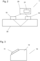
- Fig. 2 1 outlines an exemplary clamp-on ultrasonic measuring device 1 according to the invention with two ultrasonic transducers 10 mounted on the outside of a measuring tube 30, as well as an electronic measuring/operating circuit 20 for operating the ultrasonic transducers and for providing measured values of at least one property of a medium located in the measuring tube.
- the medium property can, for example, be one of the following measured variables: sound velocity, flow velocity, volume flow, and others.
- the electronic measuring/operating circuit has a memory unit 21 in which at least one specification value is stored so that the method according to the invention can be carried out.
- clamp-on ultrasonic measuring devices The functionality of clamp-on ultrasonic measuring devices is known to those skilled in the art.
- Fig. 3 shows an exemplary ultrasonic transducer 10, which has a transducer element 11, in particular a piezo element, which is arranged on a coupling element/ultrasound transmitter 12.
- the coupling element/ultrasound transmitter is contacted with the measuring tube 30 via a side facing away from the transducer element and is configured to transmit ultrasonic signals between the transducer element and the measuring tube and vice versa.
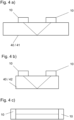
- Fig. 4 b) to c) outline exemplary standard measuring sections 40 by means of which the clamp-on ultrasonic measuring device and in particular the ultrasonic transducers of the clamp-on ultrasonic measuring device can be verified in accordance with the method according to the invention.
- Fig. 4 a shows a standard measuring section not according to the invention with a measuring tube 41 to which the ultrasonic transducers 10 are attached.
- the arrangement can be be designed such that an ultrasonic signal is simply reflected on a wall of the measuring tube 41 on a side of the measuring tube opposite the ultrasonic transducer. Since the measuring tube is used exclusively for verification purposes, it retains its properties and can therefore be used repeatedly for verification.
- the measuring tube can be at least partially filled with a liquid medium for verification.
- Ultrasonic signal reflections can be used.
- Fig. 4 b shows a standard measuring section with a measuring block 42.
- ultrasonic signal reflection occurs primarily at interfaces between the surroundings of the measuring block and the measuring block. This results in a clearer and less noisy ultrasonic signal for a receiving ultrasonic transducer.
- Fig. 4 c sketches a standard measuring section with a measuring rod 43, with the ultrasonic transducers arranged at opposite ends of the measuring rod.
- the ultrasonic signal is not reflected, but is transmitted directly via the measuring rod, i.e., without deflection between the ultrasonic transducers.
Landscapes
- Physics & Mathematics (AREA)
- Fluid Mechanics (AREA)
- General Physics & Mathematics (AREA)
- Electromagnetism (AREA)
- Measuring Volume Flow (AREA)
- Investigating Or Analyzing Materials By The Use Of Ultrasonic Waves (AREA)
- Ultra Sonic Daignosis Equipment (AREA)
Claims (6)
- Procédé (100) de vérification d'un appareil de mesure à ultrasons de type "clamp-on" (1),dans lequel l'instrument de mesure comprendau moins deux transducteurs d'ultrasons (10) aménagés pour émettre et recevoir des signaux ultrasonores,un circuit électronique de mesure/d'exploitation (20) aménagé pour exploiter le au moins un transducteur à ultrasons ainsi que pour fournir des valeurs de mesure d'au moins une grandeur de mesure ainsi que pour effectuer la vérification,dans lequel le circuit électronique de mesure/fonctionnement comprend une unité de mémoire (21),le procédé comprenant les étapes suivantes :le montage de l'appareil de mesure sur une section de mesure normalisée (30) dans une première étape de procédé (101),la distance de mesure normalisée (40) étant une distance choisie dans la liste suivante :bloc de mesure (42), jauge (43) ;activation d'un mode de vérification du circuit électronique de mesure/fonctionnement au cours d'une deuxième étape du procédé (102) ;émission d'au moins un signal ultrasonore avec au moins un transducteur ultrasonore et la réception du signal ultrasonore avec au moins un transducteur ultrasonore dans une troisième étape de procédé (103) ;détermination d'au moins une valeur de mesure d'au moins une grandeur de vérification du signal ultrasonore et la comparaison de la valeur de mesure avec au moins une valeur de spécification de la grandeur de vérification stockée dans l'unité de mémoire dans une quatrième étape de procédé (104) ;émettre un résultat de vérification dans une cinquième étape de procédé (105);sortie du mode de vérification dans une sixième étape de procédé (106).
- Procédé selon la revendication 1,
où la grandeur de vérification est une grandeur de la liste suivante :Amplitude d'un signal ultrasonore reçu ;Temps de propagation d'un signal ultrasonore ;Vitesse du son ;Différence de temps de propagation de deux signaux ultrasonores émis et reçus par paires par deux transducteurs ultrasonores, notamment en l'absence d'un milieu fluide ;Rapport signal-bruit ;Forme du signal donnée par exemple par un temps de montée, un temps de descente, une amplitude, une fréquence ;Corrélation entre un signal ultrasonore reçu et un signal ultrasonore attendu. - Procédé selon la revendication 1 ou 2,
la distance de mesure normalisée (40) étant fabriquée à partir d'au moins l'un des matériaux suivants :
Plastique, métal. - Procédé selon l'une quelconque des revendications précédentes,
dans lequel le résultat de la vérification comprend un historique de valeurs mesurées par rapport à une grandeur de spécification. - Procédé selon l'une des revendications précédentes,
dans lequel le résultat de la vérification comprend une prédiction concernant un temps de fonctionnement minimum avant de quitter un état cible. - Appareil de mesure à ultrasons Clamp-On (1) aménagé pour la mise en œuvre du procédé selon l'une des revendications précédentes comprenant :au moins deux transducteurs ultrasonores (10) aménagés pour émettre et recevoir des signaux ultrasonores, qui sont montés ou peuvent être montés sur un tube de mesure,un circuit électronique de mesure/d'exploitation (20) aménagé pour exploiter le au moins un transducteur à ultrasons ainsi que pour fournir des valeurs de mesure d'au moins une grandeur de mesure ainsi que pour effectuer la vérification,dans lequel le circuit électronique de mesure/fonctionnement présente une unité de mémoire (21) dans laquelle au moins une valeur de spécification est mémorisée.
Applications Claiming Priority (2)
| Application Number | Priority Date | Filing Date | Title |
|---|---|---|---|
| DE102020127360.6A DE102020127360A1 (de) | 2020-10-16 | 2020-10-16 | Verfahren zur Verifikation eines Clamp-On-Ultraschall-Messgeräts |
| PCT/EP2021/075129 WO2022078686A1 (fr) | 2020-10-16 | 2021-09-13 | Procédé de vérification d'un dispositif de mesure ultrasonique enfichable |
Publications (2)
| Publication Number | Publication Date |
|---|---|
| EP4229366A1 EP4229366A1 (fr) | 2023-08-23 |
| EP4229366B1 true EP4229366B1 (fr) | 2025-06-11 |
Family
ID=77914308
Family Applications (1)
| Application Number | Title | Priority Date | Filing Date |
|---|---|---|---|
| EP21777676.4A Active EP4229366B1 (fr) | 2020-10-16 | 2021-09-13 | Procédé de vérification d'un dispositif clamp-on de mesure ultrasonique |
Country Status (5)
| Country | Link |
|---|---|
| US (1) | US12492931B2 (fr) |
| EP (1) | EP4229366B1 (fr) |
| CN (1) | CN116391110A (fr) |
| DE (1) | DE102020127360A1 (fr) |
| WO (1) | WO2022078686A1 (fr) |
Citations (2)
| Publication number | Priority date | Publication date | Assignee | Title |
|---|---|---|---|---|
| DE102015107750A1 (de) * | 2015-05-18 | 2016-11-24 | Endress + Hauser Flowtec Ag | Meßsystem zum Messen wenigstens eines Parameters eines Fluids |
| WO2020126281A1 (fr) * | 2018-12-21 | 2020-06-25 | Endress+Hauser Flowtec Ag | Procédé de mise en service et/ou de contrôle d'un point de mesure de débit par ultrasons |
Family Cites Families (7)
| Publication number | Priority date | Publication date | Assignee | Title |
|---|---|---|---|---|
| EP2607864B8 (fr) | 2011-12-19 | 2017-08-02 | Endress+Hauser Consult AG | Procédé pour la vérification en ligne d'un débitmètre |
| DE102012112516A1 (de) | 2012-12-18 | 2014-06-18 | Endress + Hauser Flowtec Ag | Verfahren zur Verifizierung der Zuverlässigkeit von ermittelten Messdaten einer Ultraschall-Durchflussmessung nach der Laufzeitdifferenz-Methode und Ultraschalldurchflussmessgerät |
| US9625305B2 (en) * | 2014-03-17 | 2017-04-18 | Siemens Aktiengesellschaft | Ultrasonic transit-time flowmeter and method for detecting a failure in an ultrasonic transit-time flowmeter |
| DE102014119512A1 (de) * | 2014-12-23 | 2016-06-23 | Endress + Hauser Flowtec Ag | Durchflussmessgerät |
| DE102015106897B4 (de) | 2015-05-04 | 2021-12-02 | Endress+Hauser Flowtec Ag | Verfahren und Vorrichtung zur Verifikation des Betriebs eines Ultraschall-Durchflussmessgeräts basierend auf dem Laufzeitdifferenzenverfahren |
| WO2018162340A1 (fr) | 2017-03-07 | 2018-09-13 | Abb Schweiz Ag | Appareil et procédé de mesure de la vitesse d'écoulement d'un fluide dans un tuyau |
| DE102017130976A1 (de) * | 2017-12-21 | 2019-06-27 | Endress+Hauser Flowtec Ag | Clamp-On-Ultraschall-Durchflussmessgerät und Verfahren zum Justieren des Clamp-On-Ultraschall-Durchflussmessgeräts |
-
2020
- 2020-10-16 DE DE102020127360.6A patent/DE102020127360A1/de active Pending
-
2021
- 2021-09-13 WO PCT/EP2021/075129 patent/WO2022078686A1/fr not_active Ceased
- 2021-09-13 CN CN202180070564.0A patent/CN116391110A/zh active Pending
- 2021-09-13 US US18/249,361 patent/US12492931B2/en active Active
- 2021-09-13 EP EP21777676.4A patent/EP4229366B1/fr active Active
Patent Citations (2)
| Publication number | Priority date | Publication date | Assignee | Title |
|---|---|---|---|---|
| DE102015107750A1 (de) * | 2015-05-18 | 2016-11-24 | Endress + Hauser Flowtec Ag | Meßsystem zum Messen wenigstens eines Parameters eines Fluids |
| WO2020126281A1 (fr) * | 2018-12-21 | 2020-06-25 | Endress+Hauser Flowtec Ag | Procédé de mise en service et/ou de contrôle d'un point de mesure de débit par ultrasons |
Also Published As
| Publication number | Publication date |
|---|---|
| CN116391110A (zh) | 2023-07-04 |
| US12492931B2 (en) | 2025-12-09 |
| EP4229366A1 (fr) | 2023-08-23 |
| DE102020127360A1 (de) | 2022-04-21 |
| WO2022078686A1 (fr) | 2022-04-21 |
| US20250027805A1 (en) | 2025-01-23 |
Similar Documents
| Publication | Publication Date | Title |
|---|---|---|
| DE19606083B4 (de) | Verzögerungsleitung für einen Ultraschallmeßfühler und Verfahren zur Verwendung desselben | |
| EP3298360B1 (fr) | Procédé, produit de logiciel d'ordinateur et appareil pour déterminer un paramètre caractéristique pour évaluer un dispositif de mesure comprenant un débitmètre ultrasonore du type clamp-on et une conduite de mesure | |
| EP3298359B1 (fr) | Procédé de détermination d'une fréquence de résonance de la paroi d'une conduite, et débitmètre ultrasonore serre-tube | |
| DE3822138A1 (de) | Fluessigkeitsstand-ueberwachung | |
| EP2656017B1 (fr) | Élément de couplage d'un transducteur ultrasonique pour un débitmètre à ultrasons | |
| WO2004088252A2 (fr) | Dispositif permettant de determiner et/ou de surveiller le debit volumetrique et/ou massique d'un milieu | |
| DE102005022048A1 (de) | Vorrichtung zur Bestimmung und/oder Überwachung des Volumen- und/oder Massendurchflusses eines Messmediums | |
| DE10244772A1 (de) | Akustisches Fluidmesssystem | |
| DE102012022376A1 (de) | Druck- und Durchflussmessung mittels akustischer Wellen | |
| DE102016111133A1 (de) | Vorrichtung zur Bestimmung oder Überwachung des Volumen- und/oder Massendurchflusses eines fluiden Mediums in einer Rohrleitung | |
| EP3314210B1 (fr) | Appareil émetteur de champs doté d'un circuit de compensation pour l'élimination des impacts environnementaux | |
| EP4229366B1 (fr) | Procédé de vérification d'un dispositif clamp-on de mesure ultrasonique | |
| EP3517946B1 (fr) | Procédé de détermination d'une valeur corrigée de la vitesse sonique dépendant de la viscosité dans un fluide à analyser | |
| DE19535848C1 (de) | Vorrichtung zur Messung der akustischen Impedanz von flüssigen Medien | |
| DE102004035715B4 (de) | Schalllaufzeitmessvorrichtung | |
| EP3894799B1 (fr) | Agencement de transducteurs ultrasonores d'un appareil de mesure de debit a ultrasons a pinces, et appareil de mesure de debit a ultrasons a pinces et procede de mise en marche de l'appareil de mesure de debit a ultrasons a pinces | |
| EP3492878A1 (fr) | Procédé de détermination du temps de transit d'un signal ultrasonore dans un milieu fluide ainsi que débitmètre ultrasonore | |
| DE102008044738B4 (de) | Sensoranordnung und Detektionsverfahren zur Messung einer Eisschicht | |
| EP4356078B1 (fr) | Agencement de transducteurs ultrasonores, dispositif de mesure par ultrasons à serrage doté d'un tel agencement, et procédé de réglage du dispositif de mesure par ultrasons | |
| EP3405781B1 (fr) | Dispositif de détermination de caractéristiques d'un milieu, comprenant un élément d'amortissement et/ou un élément de guidage ouvert | |
| WO2005114112A2 (fr) | Determination de l'instant de reception d'un signal ultrasonore par detection de forme d'impulsion | |
| WO2003098166A1 (fr) | Transducteur d'ultrasons pour un debitmetre a ultrasons | |
| EP4405642B1 (fr) | Procédé de fonctionnement d'un dispositif de mesure à ultrasons et dispositif de mesure à ultrasons | |
| DE3209838A1 (de) | Verfahren und vorrichtung zur bestimmung der wanddicke mit hilfe von ultraschallimpulsen | |
| DE202021103867U1 (de) | Fluidmesseinrichtung |
Legal Events
| Date | Code | Title | Description |
|---|---|---|---|
| STAA | Information on the status of an ep patent application or granted ep patent |
Free format text: STATUS: UNKNOWN |
|
| STAA | Information on the status of an ep patent application or granted ep patent |
Free format text: STATUS: THE INTERNATIONAL PUBLICATION HAS BEEN MADE |
|
| PUAI | Public reference made under article 153(3) epc to a published international application that has entered the european phase |
Free format text: ORIGINAL CODE: 0009012 |
|
| STAA | Information on the status of an ep patent application or granted ep patent |
Free format text: STATUS: REQUEST FOR EXAMINATION WAS MADE |
|
| 17P | Request for examination filed |
Effective date: 20230406 |
|
| AK | Designated contracting states |
Kind code of ref document: A1 Designated state(s): AL AT BE BG CH CY CZ DE DK EE ES FI FR GB GR HR HU IE IS IT LI LT LU LV MC MK MT NL NO PL PT RO RS SE SI SK SM TR |
|
| DAV | Request for validation of the european patent (deleted) | ||
| DAX | Request for extension of the european patent (deleted) | ||
| RAP3 | Party data changed (applicant data changed or rights of an application transferred) |
Owner name: ENDRESS+HAUSER FLOWTEC AG |
|
| REG | Reference to a national code |
Ref country code: DE Free format text: PREVIOUS MAIN CLASS: G01F0025000000 Ref country code: DE Ref legal event code: R079 Ref document number: 502021007726 Country of ref document: DE Free format text: PREVIOUS MAIN CLASS: G01F0025000000 Ipc: G01F0025100000 |
|
| GRAP | Despatch of communication of intention to grant a patent |
Free format text: ORIGINAL CODE: EPIDOSNIGR1 |
|
| STAA | Information on the status of an ep patent application or granted ep patent |
Free format text: STATUS: GRANT OF PATENT IS INTENDED |
|
| RIC1 | Information provided on ipc code assigned before grant |
Ipc: G01F 1/66 20220101ALI20250219BHEP Ipc: G01F 25/10 20220101AFI20250219BHEP |
|
| INTG | Intention to grant announced |
Effective date: 20250311 |
|
| GRAS | Grant fee paid |
Free format text: ORIGINAL CODE: EPIDOSNIGR3 |
|
| GRAA | (expected) grant |
Free format text: ORIGINAL CODE: 0009210 |
|
| STAA | Information on the status of an ep patent application or granted ep patent |
Free format text: STATUS: THE PATENT HAS BEEN GRANTED |
|
| AK | Designated contracting states |
Kind code of ref document: B1 Designated state(s): AL AT BE BG CH CY CZ DE DK EE ES FI FR GB GR HR HU IE IS IT LI LT LU LV MC MK MT NL NO PL PT RO RS SE SI SK SM TR |
|
| REG | Reference to a national code |
Ref country code: GB Ref legal event code: FG4D Free format text: NOT ENGLISH |
|
| REG | Reference to a national code |
Ref country code: CH Ref legal event code: EP |
|
| REG | Reference to a national code |
Ref country code: DE Ref legal event code: R096 Ref document number: 502021007726 Country of ref document: DE |
|
| REG | Reference to a national code |
Ref country code: IE Ref legal event code: FG4D Free format text: LANGUAGE OF EP DOCUMENT: GERMAN |
|
| P01 | Opt-out of the competence of the unified patent court (upc) registered |
Free format text: CASE NUMBER: APP_26476/2025 Effective date: 20250604 |
|
| REG | Reference to a national code |
Ref country code: NL Ref legal event code: FP |
|
| PG25 | Lapsed in a contracting state [announced via postgrant information from national office to epo] |
Ref country code: FI Free format text: LAPSE BECAUSE OF FAILURE TO SUBMIT A TRANSLATION OF THE DESCRIPTION OR TO PAY THE FEE WITHIN THE PRESCRIBED TIME-LIMIT Effective date: 20250611 Ref country code: ES Free format text: LAPSE BECAUSE OF FAILURE TO SUBMIT A TRANSLATION OF THE DESCRIPTION OR TO PAY THE FEE WITHIN THE PRESCRIBED TIME-LIMIT Effective date: 20250611 |
|
| PGFP | Annual fee paid to national office [announced via postgrant information from national office to epo] |
Ref country code: DE Payment date: 20250919 Year of fee payment: 5 |
|
| REG | Reference to a national code |
Ref country code: LT Ref legal event code: MG9D |
|
| PG25 | Lapsed in a contracting state [announced via postgrant information from national office to epo] |
Ref country code: GR Free format text: LAPSE BECAUSE OF FAILURE TO SUBMIT A TRANSLATION OF THE DESCRIPTION OR TO PAY THE FEE WITHIN THE PRESCRIBED TIME-LIMIT Effective date: 20250912 Ref country code: NO Free format text: LAPSE BECAUSE OF FAILURE TO SUBMIT A TRANSLATION OF THE DESCRIPTION OR TO PAY THE FEE WITHIN THE PRESCRIBED TIME-LIMIT Effective date: 20250911 |
|
| PGFP | Annual fee paid to national office [announced via postgrant information from national office to epo] |
Ref country code: NL Payment date: 20250918 Year of fee payment: 5 |
|
| PG25 | Lapsed in a contracting state [announced via postgrant information from national office to epo] |
Ref country code: BG Free format text: LAPSE BECAUSE OF FAILURE TO SUBMIT A TRANSLATION OF THE DESCRIPTION OR TO PAY THE FEE WITHIN THE PRESCRIBED TIME-LIMIT Effective date: 20250611 |
|
| PGFP | Annual fee paid to national office [announced via postgrant information from national office to epo] |
Ref country code: GB Payment date: 20250919 Year of fee payment: 5 |
|
| PG25 | Lapsed in a contracting state [announced via postgrant information from national office to epo] |
Ref country code: HR Free format text: LAPSE BECAUSE OF FAILURE TO SUBMIT A TRANSLATION OF THE DESCRIPTION OR TO PAY THE FEE WITHIN THE PRESCRIBED TIME-LIMIT Effective date: 20250611 |
|
| PGFP | Annual fee paid to national office [announced via postgrant information from national office to epo] |
Ref country code: AT Payment date: 20251020 Year of fee payment: 5 Ref country code: FR Payment date: 20250922 Year of fee payment: 5 |
|
| PG25 | Lapsed in a contracting state [announced via postgrant information from national office to epo] |
Ref country code: RS Free format text: LAPSE BECAUSE OF FAILURE TO SUBMIT A TRANSLATION OF THE DESCRIPTION OR TO PAY THE FEE WITHIN THE PRESCRIBED TIME-LIMIT Effective date: 20250911 |
|
| PGFP | Annual fee paid to national office [announced via postgrant information from national office to epo] |
Ref country code: CZ Payment date: 20250908 Year of fee payment: 5 |
|
| PG25 | Lapsed in a contracting state [announced via postgrant information from national office to epo] |
Ref country code: LV Free format text: LAPSE BECAUSE OF FAILURE TO SUBMIT A TRANSLATION OF THE DESCRIPTION OR TO PAY THE FEE WITHIN THE PRESCRIBED TIME-LIMIT Effective date: 20250611 |
|
| PG25 | Lapsed in a contracting state [announced via postgrant information from national office to epo] |
Ref country code: PT Free format text: LAPSE BECAUSE OF FAILURE TO SUBMIT A TRANSLATION OF THE DESCRIPTION OR TO PAY THE FEE WITHIN THE PRESCRIBED TIME-LIMIT Effective date: 20251013 |
|
| PG25 | Lapsed in a contracting state [announced via postgrant information from national office to epo] |
Ref country code: IS Free format text: LAPSE BECAUSE OF FAILURE TO SUBMIT A TRANSLATION OF THE DESCRIPTION OR TO PAY THE FEE WITHIN THE PRESCRIBED TIME-LIMIT Effective date: 20251011 |
|
| PG25 | Lapsed in a contracting state [announced via postgrant information from national office to epo] |
Ref country code: SM Free format text: LAPSE BECAUSE OF FAILURE TO SUBMIT A TRANSLATION OF THE DESCRIPTION OR TO PAY THE FEE WITHIN THE PRESCRIBED TIME-LIMIT Effective date: 20250611 |
|
| PG25 | Lapsed in a contracting state [announced via postgrant information from national office to epo] |
Ref country code: PL Free format text: LAPSE BECAUSE OF FAILURE TO SUBMIT A TRANSLATION OF THE DESCRIPTION OR TO PAY THE FEE WITHIN THE PRESCRIBED TIME-LIMIT Effective date: 20250611 |
|
| PG25 | Lapsed in a contracting state [announced via postgrant information from national office to epo] |
Ref country code: EE Free format text: LAPSE BECAUSE OF FAILURE TO SUBMIT A TRANSLATION OF THE DESCRIPTION OR TO PAY THE FEE WITHIN THE PRESCRIBED TIME-LIMIT Effective date: 20250611 |
|
| PG25 | Lapsed in a contracting state [announced via postgrant information from national office to epo] |
Ref country code: SK Free format text: LAPSE BECAUSE OF FAILURE TO SUBMIT A TRANSLATION OF THE DESCRIPTION OR TO PAY THE FEE WITHIN THE PRESCRIBED TIME-LIMIT Effective date: 20250611 |
|
| PG25 | Lapsed in a contracting state [announced via postgrant information from national office to epo] |
Ref country code: RO Free format text: LAPSE BECAUSE OF FAILURE TO SUBMIT A TRANSLATION OF THE DESCRIPTION OR TO PAY THE FEE WITHIN THE PRESCRIBED TIME-LIMIT Effective date: 20250611 |
|
| PG25 | Lapsed in a contracting state [announced via postgrant information from national office to epo] |
Ref country code: DK Free format text: LAPSE BECAUSE OF FAILURE TO SUBMIT A TRANSLATION OF THE DESCRIPTION OR TO PAY THE FEE WITHIN THE PRESCRIBED TIME-LIMIT Effective date: 20250611 |
|
| PG25 | Lapsed in a contracting state [announced via postgrant information from national office to epo] |
Ref country code: IT Free format text: LAPSE BECAUSE OF FAILURE TO SUBMIT A TRANSLATION OF THE DESCRIPTION OR TO PAY THE FEE WITHIN THE PRESCRIBED TIME-LIMIT Effective date: 20250611 |
|
| PLBE | No opposition filed within time limit |
Free format text: ORIGINAL CODE: 0009261 |
|
| STAA | Information on the status of an ep patent application or granted ep patent |
Free format text: STATUS: NO OPPOSITION FILED WITHIN TIME LIMIT |
|
| REG | Reference to a national code |
Ref country code: CH Ref legal event code: L10 Free format text: ST27 STATUS EVENT CODE: U-0-0-L10-L00 (AS PROVIDED BY THE NATIONAL OFFICE) Effective date: 20260423 |