EP4225569B1 - Einstellsystem zum einstellen des führungsspiels einer gleitführung für bewegbare teile einer presse sowie verfahren zum einstellen der position wenigstens eines gleitblocks einer gleitführung an einer presse - Google Patents
Einstellsystem zum einstellen des führungsspiels einer gleitführung für bewegbare teile einer presse sowie verfahren zum einstellen der position wenigstens eines gleitblocks einer gleitführung an einer presse Download PDFInfo
- Publication number
- EP4225569B1 EP4225569B1 EP21791291.4A EP21791291A EP4225569B1 EP 4225569 B1 EP4225569 B1 EP 4225569B1 EP 21791291 A EP21791291 A EP 21791291A EP 4225569 B1 EP4225569 B1 EP 4225569B1
- Authority
- EP
- European Patent Office
- Prior art keywords
- guide
- press
- adjustment system
- wedge
- spindle
- Prior art date
- Legal status (The legal status is an assumption and is not a legal conclusion. Google has not performed a legal analysis and makes no representation as to the accuracy of the status listed.)
- Active
Links
Images

Classifications
-
- B—PERFORMING OPERATIONS; TRANSPORTING
- B30—PRESSES
- B30B—PRESSES IN GENERAL
- B30B15/00—Details of, or accessories for, presses; Auxiliary measures in connection with pressing
- B30B15/04—Frames; Guides
- B30B15/041—Guides
Definitions
- the invention relates to an adjustment system for adjusting the guide play of a sliding guide for movable parts of a press, with at least one adjustable guide element, comprising at least one sliding block adjustable transversely to the direction of movement of the part of the press to be guided, at least one adjusting wedge and at least one guide wedge, the adjustment of which is relative to one another causes the sliding block to shift transversely to the direction of movement of the movable part of the press.
- a press in the sense of the present invention is, for example, a metal extruder as a lying or standing extruder with a press frame and at least one running bar or pickup holder which is slidably guided within the press frame, for example on guide columns.
- a generic adjustment system is, for example, from EP 3 003 701 B1 known.
- the EP 3 003 701 B1 relates to a system and method for adjusting slides of a movable cross member of a press with respect to a column of the press on which the slide block can slide.
- the adjustment system includes a first wedge configured to be integral with the movable crosspiece, a second wedge to which the slide block is fixed, a pin defining an axis and having a first end eccentric with respect to is arranged on the axle, the first end being received in a cavity provided in the second wedge and a first actuating means for actuating the pin, which is designed so that by rotating the pin the first end causes the second wedge to slide on the first Wedge caused along a direction transverse to the axis.
- the pin is moved between a locked and an unlocked position by means of a second actuating means, which is designed as a hydraulic cylinder.
- the pin In order to change the position of the movable wedge and thus the position of the sliding block, the pin must first be moved into the unlocked position. After that the game becomes over a Rotation of the pin is adjusted with its eccentric end. After the adjustment has been completed, the pin is moved back into the locked position.
- JP 2013-220 474 A discloses in particular the preamble of claim 1.
- the invention is based on the object of providing an adjustment system of the type mentioned, which is structurally simple and can be operated automatically.
- the object is further solved by a method for adjusting the position of at least one sliding block of a sliding guide on a press with such an adjustment system with the features of claim 10.
- an adjustment system for adjusting the guide play of a sliding guide for movable parts of a press, the adjustment system having at least one adjustable guide element which has at least one sliding block adjustable transversely to the direction of movement of the part of the press to be guided, at least one adjusting wedge and comprises at least one guide wedge, the adjustment of which relative to one another causes a displacement of the sliding block transversely to the direction of movement of the movable part, the adjustment system according to the invention being characterized in that the adjusting wedge is infinitely adjustable by means of at least one spindle drive.
- the adjustment system according to the invention can be an integral part of a press, but this can also be designed as a correspondingly prefabricated separate structural unit.
- Movable parts of a press are, for example, running bars, pickup holders and the like, which can be moved, for example, between cross bars or yokes of a press frame on guide columns or the like.
- the adjustment system according to the invention can preferably be installed in an open-die forging, drop-die, isothermal forging, ring blank, hole, drawing, deep-drawing and/or extrusion press.
- the adjustment system according to the invention can be implemented very easily, particularly in terms of construction.
- the continuous adjustment by means of a spindle drive makes it possible to achieve an automated adjustment of the guide play of the sliding guide relatively easily.
- the essence of the invention is that the adjustability is achieved via a pair of wedges comprising an adjusting wedge and a guide wedge that interacts with it, the adjusting wedge being continuously displaceable in the direction of the spindle axis via a spindle connected to it and thus extending the guide wedge perpendicular to the spindle axis. or let it enter.
- the adjusting wedge and the guide wedge rest against each other, with the adjusting wedge being movable parallel to the spindle axis by actuating the spindle drive and thereby displacing the guide wedge transversely to the spindle axis.
- the spindle drive comprises at least one spindle driven by a servomotor, which cooperates with a movement thread of the adjusting wedge.
- the adjusting wedge can be designed with a corresponding threaded hole.
- a servomotor in the sense of the invention can also have a gear and / or act on more than one spindle.
- At least one measuring sensor is provided which detects the guide play of the sliding guide and outputs this to a control and/or regulating device for automatically adjusting the guide play.
- the spindle, the adjusting wedge and the guide wedge can be arranged in a common housing and form a structural unit with the sliding block as an adjustable guide element.
- the spindle is expediently rotatably mounted in a socket in the housing. Furthermore, the sliding block is expediently attached to the guide wedge in a replaceable manner.
- a press is provided with an adjustment system of the type described above.
- the press can include a press frame and at least one running bar and/or pickup holder that can be moved within the press frame, as well as sliding guides for the running bar and/or the pickup holder.
- the sliding guides can be provided, for example, on guide columns of the press frame, each of which interacts with a sliding block of an adjustment system according to the invention.
- the press can be designed, for example, as a 2 or 4 column press.
- a method for adjusting the position of at least one slide block of a slide guide on a press with an adjustment system of the type described above is characterized in that the guide play between the sliding block and a sliding surface of the part of the press to be moved is measured and compared with a predetermined guide play as a target value, whereby if necessary the spindle of the adjustment system is adjusted or rotated until this actual guidance play (actual play) matches the specified or predetermined required guidance play (target play).
- the adjustment system When starting up for the first time, it is advantageous if the adjustment system is calibrated and the measurement data recorded is saved. In comparison with later measurement data, forecasts can be derived about the further development of the press or maintenance intervals.
- the recorded measurement data is preferably recorded in a data storage device and prepared for later evaluation. This makes it possible, for example, to compare and/or explain later quality fluctuations in the product with the measurement data from the press. Furthermore, it is advantageous if the measurement data is visualized for the system operator and deviations from the target value are highlighted in color.
- the spindle can be automatically adjusted via an actuator depending on a measured value of the guide play recorded by a sensor.
- a stepper motor for example, can be provided as the actuator.
- the adjustment of the spindle is detected by means of at least one control value transmitter and a time for the necessary replacement of the sliding block is calculated from the adjustment path completed.
- the adjustment path that has already been completed can, for example, be summed up in a control and/or regulating device.
- the adjustment system comprises at least one guide element 1 of the type described below.
- the adjustment system can comprise a plurality of guide elements of the type described below as well as means for controlling and/or automatically actuating the guide element 1 or a plurality of guide elements.
- the guide element 1 shown in the figures comprises a housing 2, in which a spindle 3 extends, which is rotatably mounted in a bushing 4.
- the spindle 3 extends through first and second threaded bores 6, 7 of an adjusting wedge 5, which can be displaced within the housing 2 by rotating the spindle 3.
- the thread of the threaded holes 6, 7 is a movement thread that is complementary to the thread of the spindle 3.
- the adjusting wedge 5 rests with a sliding bevel against a sliding bevel of a guide wedge 8, which is connected to a sliding block 9 or a sliding plate.
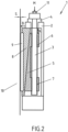
- the sliding block 9 is designed as a wearing part and is like this Figure 2 can be seen, in the installed position of the guide element 1 parallel and at a predetermined distance S to a guide column 10, not shown Press arranged.
- the distance S of the sliding block 9 to the guide roller 10 defines the guiding play of the sliding guide.
- the spindle 3 is provided at its end protruding from the housing 2 with an engagement 11 for a tool or for the drive axle of a motor, not shown.
- the spindle 3 is rotated either by hand or with a motor.
- the rotational movement causes the adjusting wedge 5 to move in or against the direction of the in Figure 2 arrow A shown, whereby the guide wedge moves in or against the direction of the also in Figure 2 Arrow B shown slides and the distance S between the guide columns 10 and the sliding block 9 either increases or decreases.
Landscapes
- Engineering & Computer Science (AREA)
- Mechanical Engineering (AREA)
- Presses And Accessory Devices Thereof (AREA)
- Press Drives And Press Lines (AREA)
Description
- Die Erfindung betrifft ein Einstellsystem zum Einstellen des Führungsspiels einer Gleitführung für bewegbare Teile einer Presse, mit wenigstens einem einstellbaren Führungselement, umfassend wenigstens einen quer zur Bewegungsrichtung des zu führenden Teils der Presse verstellbaren Gleitblock, wenigstens einen Stellkeil und wenigstens einen Führungskeil, deren Verstellung relativ zueinander eine Verlagerung des Gleitblocks quer zur Bewegungsrichtung des bewegbaren Teils der Presse bewirkt. Eine Presse im Sinne der vorliegenden Erfindung ist beispielsweise eine Metall-Strangpresse als liegende oder stehende Strangpresse mit einem Pressenrahmen und wenigstens einem innerhalb des Pressenrahmens beispielsweise an Führungssäulen gleitend geführten Laufholm oder Aufnehmerhalter.
- Ein gattungsgemäßes Einstellsystem ist beispielsweise aus der
EP 3 003 701 B1 bekannt. DieEP 3 003 701 B1 betrifft ein System und Verfahren zur Einstellung von Gleitstücken eines beweglichen Querträgers einer Presse in Bezug auf eine Säule der Presse, an der der Gleitblock gleiten kann. Das Einstellsystem umfasst einen ersten Keil, der so ausgebildet ist, dass er einteilig mit dem bewegbaren Querstück ausgebildet ist, einen zweiten Keil, an dem der Gleitblock fixiert ist, einen Stift, der eine Achse definiert und ein erstes Ende aufweist, das exzentrisch in Bezug auf die Achse angeordnet ist, wobei das erste Ende in einem in dem zweiten Keil vorgesehenen Hohlraum aufgenommen wird und ein erstes Betätigungsmittel zur Betätigung des Stiftes, das so ausgebildet ist, dass durch Drehen des Stiftes das erste Ende ein Gleiten des zweiten Keils an dem ersten Keil entlang einer Richtung quer zur Achse bewirkt. Der Stift wird mittels eines zweiten Betätigungmittels, welches als Hydraulikzylinder ausgebildet ist, zwischen einer verriegelten und einer entriegelten Stellung bewegt. Um die Lage des bewegbaren Keiles und damit die Stellung des Gleitblocks zu verändern, muss der Stift zunächst in die entriegelte Stellung bewegt werden. Danach wird das Spiel über eine Drehung des Stifts mit dessen exzentrischem Ende eingestellt. Nach vollzogener Einstellung wird der Stift wieder in die verriegelte Stellung bewegt. - Dieser Mechanismus ist verhältnismäßig aufwendig. Die Verstellung ist zeitintensiv und eine Automatisierung dieser ist schwierig.
- Weiterer Stand der Technik ist beispielsweise aus dem Dokument
CN 107243586 A bekannt. Dort ist ebenfalls ein Einstellsystem mit gegeneinander verstellbaren Keilen beschrieben, bei welchem eine Justierung des Spiels mittels Unterlegscheiben bzw. mittels Shims vorgenommen wird. - Weiterer Stand der Technik ist aus den Dokumenten
CN 201669364 U ,DE 39 01 961 A1 ,JP 2525281 JP H04 141 337 DE 197 28 893 A1 ,DE 27 58 340 A1 ,CN 201 046 513 Y ,WO 2011/047881 A1 undUS 5, 775, 212 bekannt. - Ein anderes gattungsgemäßes Einstellsystem ist jeweils aus den Druckschriften
JP 2013-220 474 A JP 2011-152 553 A JP 2011 152553 A - Der Erfindung liegt die Aufgabe zugrunde, ein Einstellsystem der eingangs genannten Art bereitzustellen, welches konstruktiv einfach ist und automatisch betrieben werden kann.
- Die Aufgabe wird gelöst durch ein Einstellsystem mit den Merkmalen des Anspruchs 1.
- Die Aufgabe wird weiterhin gelöst durch ein Verfahren zum Einstellen der Position wenigstens eines Gleitblocks einer Gleitführung an einer Presse mit einem solchen Einstellsystem mit den Merkmalen des Anspruchs 10.
- Vorteilhafte Ausgestaltungen der Erfindung ergeben sich aus den Unteransprüchen.
- Nach einem ersten Gesichtspunkt der Erfindung ist ein Einstellsystem zum Einstellen des Führungsspiels einer Gleitführung für bewegbare Teile einer Presse vorgesehen, wobei das Einstellsystem wenigstens ein einstellbares Führungselement aufweist, das wenigstens einen quer zur Bewegungsrichtung des zu führenden Teils der Presse verstellbaren Gleitblock, wenigstens einen Stellkeil und wenigstens einen Führungskeil umfasst, deren Verstellung relativ zueinander eine Verlagerung des Gleitblocks quer zur Bewegungsrichtung des bewegbaren Teils bewirken, wobei sich das Einstellsystem gemäß der Erfindung dadurch auszeichnet, dass der Stellkeil stufenlos mittels wenigstens eines Spindeltriebs verstellbar ist. Das Einstellsystem gemäß der Erfindung kann fester Bestandteil einer Presse sein, dieses kann jedoch auch als entsprechend vorkonfektionierte separate Baueinheit ausgebildet sein. Bewegbare Teile einer Presse sind beispielsweise Laufholme, Aufnehmerhalter und dergleichen, welche beispielsweise zwischen Querholmen oder Jochen eines Pressenrahmens an Führungssäulen oder dergleichen verfahrbar sind. Bevorzugt ist das erfindungsgemäße Einstellsystem bei einer Freiformschmiede-, Gesenk-, Isothermschmiede, Ring-Rohling-, Loch-, Zieh-, Tiefzieh- und / oder Strangpresse einbaubar.
- Das Einstellsystem gemäß der Erfindung ist insbesondere konstruktiv sehr einfach realisierbar. Die stufenlose Verstellung mittels eines Spindeltriebes ermöglicht es, verhältnismäßig einfach eine automatisierte Einstellung des Führungsspiels der Gleitführung zu bewerkstelligen.
- Der Kern der Erfindung besteht darin, dass die Einstellbarkeit über ein Keilpaar umfassend einen Stellkeil und einen mit diesem zusammenwirkenden Führungskeil bewerkstelligt wird, wobei der Stellkeil über eine mit ihm verbundene Spindel in Richtung der Spindelachse stufenlos verlagerbar ist und somit den Führungskeil senkrecht zur Spindelachse aus- oder einfahren lässt. Der Stellkeil und der Führungskeil liegen aneinander an, wobei der Stellkeil durch Betätigung des Spindeltriebs parallel zur Spindelachse bewegbar ist und dabei den Führungskeil quer zur Spindelachse verlagert.
- Bei dem Einstellsystem gemäß der Erfindung ist vorgesehen, dass der Spindeltrieb wenigstens eine mit einem Stellmotor angetriebene Spindel umfasst, die mit einem Bewegungsgewinde des Stellkeils zusammenwirkt. Der Stellkeil kann mit einer entsprechenden Gewindebohrung ausgebildet sein. Alternativ ist es möglich, dass der Stellkeil an einer Spindelmutter befestigt ist, in welche die Spindel eingreift. Ein Stellmotor im erfindungsgemäßen Sinne kann auch ein Getriebe aufweisen und / oder auf mehr als eine Spindel wirken.
- Weiterhin erfindungsgemäß ist wenigstens ein Messwertgeber vorgesehen, der das Führungsspiel der Gleitführung erfasst und dieses an eine Steuer- und oder Regeleinrichtung zur automatischen Nachstellung des Führungsspiels ausgibt.
- Die Spindel, der Stellkeil und der Führungskeil können in einem gemeinsamen Gehäuse angeordnet sein und mit dem Gleitblock eine Baueinheit als einstellbares Führungselement bilden.
- Zweckmäßigerweise ist die Spindel drehbar in einer Buchse des Gehäuses gelagert. Weiterhin zweckmäßigerweise ist der Gleitblock auswechselbar an dem Führungskeil befestigt.
- Nach einem weiteren Gesichtspunkt der Erfindung wird eine Presse mit einem Einstellsystem der vorstehend beschriebenen Art bereitgestellt. Die Presse kann einen Pressenrahmen und wenigstens einen innerhalb des Pressenrahmens verfahrbaren Laufholm und/oder Aufnehmerhalter sowie Gleitführungen für den Laufholm und/oder den Aufnehmerhalter umfassen. Die Gleitführungen können beispielsweise an Führungssäulen des Pressenrahmens vorgesehen sein, die jeweils mit einem Gleitblock eines Einstellsystems gemäß der Erfindung zusammenwirken. Die Presse kann beispielsweise als 2 oder 4 Säulenpresse ausgebildet sein.
- Nach einem weiteren Gesichtspunkt der Erfindung wird ein Verfahren zum Einstellen der Position wenigstens eines Gleitblocks einer Gleitführung an einer Presse mit einem Einstellsystem der vorstehend beschriebenen Art bereitgestellt. Das Verfahren zeichnet sich dadurch aus, dass das Führungsspiel zwischen dem Gleitblock und einer Gleitfläche des zu bewegenden Teils der Presse gemessen und mit einem vorgegebenen Führungsspiel als Sollwert verglichen wird, wobei gegebenenfalls die Spindel des Einstellsystems solange verstellt bzw. so lange gedreht wird, bis das tatsächliche Führungsspiel (Ist-Spiel) mit dem vorgegebenen bzw. vorbestimmten erforderlichen Führungsspiel (Soll-Spiel) übereinstimmt.
- Bei der ersten Inbetriebnahme ist es vorteilhaft, wenn das Einstellsystem kalibriert wird und die hierbei erfassten Messdaten gesichert werden. Im Vergleich mit späteren Messdaten können dadurch beispielsweise Prognosen über die weitere Entwicklung der Presse oder Wartungsintervalle abgeleitet werden. Die erfassten Messdaten werden bevorzugt auf einem Datenspeicher erfasst und für eine spätere Auswertung aufbereitet. Hierdurch können beispielsweise spätere Qualitätsschwankungen des Produktes mit den Messdaten der Presse verglichen und / oder erklärt werden. Weiterhin ist es vorteilhaft, wenn die Messdaten dem Anlagenbediener visualisiert werden und Abweichungen vom Sollwert farblich hervorgehoben werden. Die Spindel kann bei dem Verfahren gemäß der Erfindung über einen Stellantrieb automatisch in Abhängigkeit eines von einem Messwertgeber erfassten Messwerts des Führungsspiels verstellt werden. Als Stellantrieb kann beispielsweise ein Schrittmotor vorgesehen sein.
- Bei einer besonders bevorzugten Variante des Verfahrens gemäß der Erfindung ist vorgesehen, dass die Verstellung der Spindel mittels wenigstens eines Stellwertgebers erfasst wird und aus dem vollzogenen Verstellweg ein Zeitpunkt für den notwendigen Austausch des Gleitblocks errechnet wird. Der bereits vollzogene Verstellweg kann beispielsweise in einer Steuer- und/oder Regeleinrichtung aufsummiert werden.
- Die Erfindung wird nachstehend unter Bezugnahme auf ein in den beigefügten Zeichnungen dargestelltes Ausführungsbeispiel erläutert.
- Es zeigen:
- Figur 1
- eine Schnittansicht eines einstellbaren Führungselements des Einstellsystems gemäß der Erfindung und
- Figur 2
- eine der
Figur 1 entsprechende Schnittansicht des einstellbaren Führungselements in Einbaulage an einer Presse. - Das erfindungsgemäße Einstellsystem umfasst wenigstens ein Führungselement 1 der nachstehend beschriebenen Art. Das Einstellsystem kann eine Vielzahl von Führungselementen der nachstehend beschriebenen Art sowie Mittel zur Steuerung und/oder automatischen Betätigung des Führungselements 1 oder einer Vielzahl von Führungselementen umfassen.
- Das in den Figuren dargestellte Führungselement 1 umfasst ein Gehäuse 2, in welchem sich eine Spindel 3 erstreckt, die drehbar in einer Buchse 4 gelagert ist. Die Spindel 3 erstreckt sich durch erste und zweite Gewindebohrungen 6, 7 eines Stellkeils 5, der durch Drehen der Spindel 3 innerhalb des Gehäuses 2 verlagerbar ist. Das Gewinde der Gewindebohrungen 6, 7 ist ein komplementär zu dem Gewinde der Spindel 3 ausgebildetes Bewegungsgewinde. Der Stellkeil 5 liegt mit einer Gleitschrägen gegen eine Gleitschräge eines Führungskeils 8 an, der mit einem Gleitblock 9 bzw. einer Gleitplatte verbunden ist. Der Gleitblock 9 ist als Verschleißteil ausgebildet und ist, wie dies aus
Figur 2 ersichtlich ist, in Einbaulage des Führungselements 1 parallel und mit einem vorgegebenen Abstand S zu einer Führungssäule 10 einer nicht dargestellten Presse angeordnet. Der Abstand S des Gleitblocks 9 zu der Führungsrolle 10 definiert das Führungsspiel der Gleitführung. - Die Spindel 3 ist an ihrem aus dem Gehäuse 2 hervortretenden Ende mit einem Eingriff 11 für ein Werkzeug oder für die Antriebsachse eines nicht dargestellten Motors versehen. Um das Spiel S einzustellen, wird die Spindel 3 entweder von Hand oder mit einem Motor gedreht. Die Drehbewegung lässt den Stellkeil 5 in oder gegen die Richtung des in
Figur 2 eingezeichneten Pfeiles A gleiten, wobei der Führungskeil dadurch in oder gegen die Richtung des ebenfalls inFigur 2 dargestellten Pfeiles B gleitet und den Abstand S zwischen der Führungssäulen 10 und dem Gleitblock 9 entweder vergrößert oder verringert. -
- 1
- Führungselement
- 2
- Gehäuse
- 3
- Spindel
- 4
- Buchse
- 5
- Stellkeil
- 6
- erste Gewindebohrung
- 7
- zweite Gewindebohrung
- 8
- Führungskeil
- 9
- Gleitblock
- 10
- Führungssäulen
- 11
- Eingriff
- A
- Pfeil
- B
- Pfeil
- S
- Abstand
Claims (10)
- Einstellsystem zum Einstellen des Führungsspiels einer Gleitführung für bewegbare Teile einer Presse, mit wenigstens einem einstellbaren Führungselement (1), umfassend wenigstens einen quer zur Bewegungsrichtung des zu führenden Teils der Presse verstellbaren Gleitblock (9), wenigstens einen Stellkeil (5) und wenigstens einen mit dem Stellkeil (5) zusammenwirkenden Führungskeil (8), deren Verstellung relativ zueinander eine Verlagerung des Gleitblocks (9) quer zur Bewegungsrichtung des bewegbaren Teils bewirkt, wobei der Stellkeil (5) stufenlos verstellbar ist dadurch gekennzeichnet, dass der Stellkeil (5) mittels wenigstens eines Spindeltriebs verstellt wird, dass der Spindeltrieb wenigstens eine mit einem Stellmotor angetriebene Spindel (3) umfasst, die mit einem Bewegungsgewinde des Stellkeils (5) zusammenwirkt und dass wenigstens ein Messwertgeber vorgesehen ist, der das Führungsspiel der Gleitführung erfasst und dieses an eine Steuer- und/oder Regeleinrichtung zur automatischen Nachstellung des Führungsspiels ausgibt.
- Einstellsystem nach Anspruch 1, dadurch gekennzeichnet, dass die Spindel (3), der Stellkeil (5) und der Führungskeil (8) in einem gemeinsamen Gehäuse (2) angeordnet sind und mit dem Gleitblock (9) eine Baueinheit bilden.
- Einstellsystem nach Anspruch 2, dadurch gekennzeichnet, dass die Spindel (3) drehbar in einer Buchse (4) des Gehäuses (2) gelagert ist.
- Einstellsystem nach einem der Ansprüche 1 bis 3, dadurch gekennzeichnet, dass der Gleitblock (9) auswechselbar an dem Führungskeil (8) befestigt ist
- Einstellsystem nach einem der Ansprüche 1 bis 4, dadurch gekennzeichnet, dass das bewegbare Teil der Presse einen Stößel aufweist oder teilweise als Stößel ausgebildet ist.
- Presse mit einem Einstellsystem nach einem der Ansprüche 1 bis 5.
- Presse nach Anspruch 6 mit wenigstens einem Pressenrahmen und mit wenigstens einem innerhalb des Pressenrahmens verfahrbaren Laufholm und/oder mit wenigstens einem Aufnehmerhalter sowie mit Gleitführungen für den Laufholm und/oder den Aufnehmerhalter.
- Verfahren zum Einstellen der Position wenigstens eines Gleitblocks einer Gleitführung an einer Presse mit einem Einstellsystem nach einem der Ansprüche 1 bis 5, dadurch gekennzeichnet, dass das Führungsspiel zwischen dem Gleitblock und einer Gleitfläche des zu bewegenden Teils der Presse gemessen und mit einem vorgegebenen Führungsspiel (Sollwert) verglichen wird und die Spindel des Einstellsystems solange verdreht wird, bis das tatsächliche Führungsspiel mit dem vorgegebenen Führungsspiel übereinstimmt.
- Verfahren nach Anspruch 8, dadurch gekennzeichnet, dass die Spindel über einen Stellantrieb automatisch in Abhängigkeit eines von einem Messwertgeber erfassten Messwertes verstellt wird.
- Verfahren nach einem der Ansprüche 8 oder 9, dadurch gekennzeichnet, dass die Verstellung der Spindel mittels wenigstens eines Stellweggebers erfasst wird und aus dem vollzogenen Verstellweg ein Zeitpunkt für den notwendigen Austausch des Gleitblocks errechnet wird.
Applications Claiming Priority (2)
| Application Number | Priority Date | Filing Date | Title |
|---|---|---|---|
| DE102020212830.8A DE102020212830B4 (de) | 2020-10-12 | 2020-10-12 | Einstellsystem zum Einstellen des Führungsspiels einer Gleitführung für bewegbare Teile einer Presse sowie Verfahren zum Einstellen der Position wenigstens eines Gleitblocks einer Gleitführung an einer Presse |
| PCT/EP2021/077881 WO2022078903A1 (de) | 2020-10-12 | 2021-10-08 | Einstellsystem zum einstellen des führungsspiels einer gleitführung für bewegbare teile einer presse sowie verfahren zum einstellen der position wenigstens eines gleitblocks einer gleitführung an einer presse |
Publications (2)
| Publication Number | Publication Date |
|---|---|
| EP4225569A1 EP4225569A1 (de) | 2023-08-16 |
| EP4225569B1 true EP4225569B1 (de) | 2024-02-14 |
Family
ID=78179374
Family Applications (1)
| Application Number | Title | Priority Date | Filing Date |
|---|---|---|---|
| EP21791291.4A Active EP4225569B1 (de) | 2020-10-12 | 2021-10-08 | Einstellsystem zum einstellen des führungsspiels einer gleitführung für bewegbare teile einer presse sowie verfahren zum einstellen der position wenigstens eines gleitblocks einer gleitführung an einer presse |
Country Status (6)
| Country | Link |
|---|---|
| US (1) | US12391017B2 (de) |
| EP (1) | EP4225569B1 (de) |
| JP (1) | JP2023544631A (de) |
| CN (1) | CN116615330B (de) |
| DE (1) | DE102020212830B4 (de) |
| WO (1) | WO2022078903A1 (de) |
Families Citing this family (1)
| Publication number | Priority date | Publication date | Assignee | Title |
|---|---|---|---|---|
| CN117259538B (zh) * | 2023-10-31 | 2024-04-05 | 武汉卫亚汽车零部件有限公司 | 一种汽车配件冲压设备及冲压方法 |
Family Cites Families (24)
| Publication number | Priority date | Publication date | Assignee | Title |
|---|---|---|---|---|
| JPS5255937U (de) * | 1975-10-14 | 1977-04-22 | ||
| DE2758340A1 (de) | 1977-12-27 | 1979-07-05 | Pfister Waagen Gmbh | Hydrostatische stellvorrichtung |
| DE3817722A1 (de) | 1988-05-25 | 1989-12-14 | Raschig Ag | Verwendung von 2-substituierten ethansulfon-verbindungen als galvanotechnische hilfsstoffe |
| DE3901961A1 (de) | 1989-01-24 | 1990-08-02 | Hasenclever Maschf Sms | Liegende strangpresse |
| JPH0347619A (ja) * | 1989-07-12 | 1991-02-28 | Mitsui Eng & Shipbuild Co Ltd | 押出しプレスのプレス芯測定装置 |
| DE3935787A1 (de) * | 1989-10-27 | 1991-05-02 | Beche & Grohs Gmbh | Presse, insbesondere spindelpresse, und verfahren zum betreiben einer presse |
| JPH0414137A (ja) | 1990-05-07 | 1992-01-20 | Sanyo Electric Co Ltd | ファジィ推論制御方法 |
| JP2525281Y2 (ja) | 1990-08-09 | 1997-02-05 | 範郎 門前 | ローラシャフトの圧入装置 |
| JP2525281B2 (ja) | 1990-10-01 | 1996-08-14 | オークマ株式会社 | マシニングセンタの横桁クランプ方法 |
| EP0741001B1 (de) * | 1995-05-04 | 2002-02-06 | Gietz AG | Präge-Druck- und Stanzmaschine |
| JPH0966399A (ja) | 1995-08-31 | 1997-03-11 | Asahi Seiki Kogyo Kk | 金属プレス機用スライドガイドのジブ構造 |
| US5909705A (en) | 1996-07-08 | 1999-06-08 | The Minster Machine Company | Vacuum seal for slide guiding |
| DE19857744B4 (de) * | 1998-12-15 | 2007-05-16 | Schuler Pressen Gmbh & Co | Presse mit Stempelverstellung, insbesondere zur Massivumformung |
| DE102007012638A1 (de) * | 2007-03-16 | 2008-09-18 | Heidelberger Druckmaschinen Ag | Bogenstanz- und -prägemaschine |
| CN201046513Y (zh) | 2007-04-18 | 2008-04-16 | 邯郸钢铁股份有限公司 | 一种下剪刀位移式剪刃间隙调节装置 |
| AT509074B1 (de) | 2009-10-23 | 2011-06-15 | Rw Sollinger Huette Gmbh | Bauwerklager |
| JP2011152553A (ja) | 2010-01-27 | 2011-08-11 | Sumitomo Heavy Industries Techno-Fort Co Ltd | プレスのギブクリアランス調整装置 |
| CN201669364U (zh) | 2010-04-09 | 2010-12-15 | 太原重工股份有限公司 | 一种自由锻造液压机抗偏载的加载系统 |
| CN102555274A (zh) * | 2011-12-09 | 2012-07-11 | 苏州工业园区高登威科技有限公司 | 液压机 |
| JP5920776B2 (ja) | 2012-04-17 | 2016-05-18 | 株式会社阪村ホットアート | 横型多段式熱間フォーマー。 |
| ITMI20130898A1 (it) * | 2013-05-31 | 2014-12-01 | Danieli Off Mecc | Sistema di regolazione pattini di una traversa mobile di una pressa |
| CN107243586A (zh) | 2017-08-03 | 2017-10-13 | 南通大力锻压机床有限公司 | 一种大型偏负载多功能锻造液压机 |
| DE102018111366B4 (de) * | 2018-05-14 | 2024-03-07 | F I B R O Gmbh | Keiltrieb mit justierbarer Führungsvorrichtung |
| CN210706218U (zh) * | 2019-07-31 | 2020-06-09 | 安徽省华夏机床制造有限公司 | 一种伺服液压机滑块导向机构 |
-
2020
- 2020-10-12 DE DE102020212830.8A patent/DE102020212830B4/de active Active
-
2021
- 2021-10-08 CN CN202180077504.1A patent/CN116615330B/zh active Active
- 2021-10-08 US US18/031,050 patent/US12391017B2/en active Active
- 2021-10-08 JP JP2023521730A patent/JP2023544631A/ja active Pending
- 2021-10-08 EP EP21791291.4A patent/EP4225569B1/de active Active
- 2021-10-08 WO PCT/EP2021/077881 patent/WO2022078903A1/de not_active Ceased
Also Published As
| Publication number | Publication date |
|---|---|
| CN116615330B (zh) | 2025-11-14 |
| EP4225569A1 (de) | 2023-08-16 |
| CN116615330A (zh) | 2023-08-18 |
| US20230364878A1 (en) | 2023-11-16 |
| US12391017B2 (en) | 2025-08-19 |
| JP2023544631A (ja) | 2023-10-24 |
| DE102020212830A1 (de) | 2022-04-14 |
| DE102020212830B4 (de) | 2022-08-18 |
| WO2022078903A1 (de) | 2022-04-21 |
Similar Documents
| Publication | Publication Date | Title |
|---|---|---|
| EP4025359B1 (de) | Schrägwalzaggregat sowie verfahren zum anstellen des walzkalibers eines schrägwalzaggregats | |
| DE3033449C2 (de) | Zweistufiger scherenstromabnehmer | |
| EP3409391B1 (de) | Werkzeugeinheit für eine strangpressmaschine zum kontinuierlichen herstellen eines profils aus einem umformbaren strangpressgut | |
| DE102008025351A1 (de) | Umformmaschine | |
| DE10028165A1 (de) | Kaltwalzmaschine | |
| DE102020212830B4 (de) | Einstellsystem zum Einstellen des Führungsspiels einer Gleitführung für bewegbare Teile einer Presse sowie Verfahren zum Einstellen der Position wenigstens eines Gleitblocks einer Gleitführung an einer Presse | |
| EP3370890B1 (de) | Vorrichtung zum anstellen einer stauchwalze eines stauchgerüsts | |
| EP1648626B1 (de) | Walzvorrichtung | |
| EP1729037B1 (de) | Kegelringgetriebe | |
| DE3238630A1 (de) | Maschine zum zerkleinern von gut, insbesondere von keramischem oder aehnlichem mahlgut | |
| DE3428948A1 (de) | Numerisch gesteuerte kreisschere und verfahren zur einstellung der dazugehoerenden messereinheiten | |
| EP3251788B1 (de) | Vorrichtung zum abstützen eines zu bearbeitenden werkstücks | |
| DE19611782C2 (de) | Verfahren und Vorrichtung zum Herstellen eines Hohlkörpers aus massivem Rundstahl | |
| DE2832049C2 (de) | Walzgerüst | |
| EP3544750B1 (de) | Stauchgerüst mit einer anstellzylinderschnellverstellung | |
| EP1943032B1 (de) | Vorrichtung zum angleichen von arbeitswalzen an die walzlinie | |
| EP1310309B1 (de) | Tangential-Rollkopf | |
| WO2025251099A1 (de) | Stellvorrichtung für gussformen | |
| DE10063560C2 (de) | Einrichtung zur Werkzeughöheneinstellung an Stanzpressen sowie Stanzpresse | |
| EP3706933B1 (de) | Strangführungssegment und stranggiessanlage | |
| EP1862234A2 (de) | Vorrichtung zum Formen von Hohlprofilen | |
| EP0495054A1 (de) | Schneid- und umformmaschine mit einer in einem bewegten maschinenteil befindlichen justiervorrichtung | |
| DE4018103A1 (de) | Vorrichtung zum einspannen und vorschub einer luppe in einem rohrkaltwalzwerk | |
| EP2047974B1 (de) | Walzenanordnung | |
| EP1316370A2 (de) | Walzenanordnung |
Legal Events
| Date | Code | Title | Description |
|---|---|---|---|
| STAA | Information on the status of an ep patent application or granted ep patent |
Free format text: STATUS: UNKNOWN |
|
| STAA | Information on the status of an ep patent application or granted ep patent |
Free format text: STATUS: THE INTERNATIONAL PUBLICATION HAS BEEN MADE |
|
| PUAI | Public reference made under article 153(3) epc to a published international application that has entered the european phase |
Free format text: ORIGINAL CODE: 0009012 |
|
| STAA | Information on the status of an ep patent application or granted ep patent |
Free format text: STATUS: REQUEST FOR EXAMINATION WAS MADE |
|
| 17P | Request for examination filed |
Effective date: 20230512 |
|
| AK | Designated contracting states |
Kind code of ref document: A1 Designated state(s): AL AT BE BG CH CY CZ DE DK EE ES FI FR GB GR HR HU IE IS IT LI LT LU LV MC MK MT NL NO PL PT RO RS SE SI SK SM TR |
|
| GRAP | Despatch of communication of intention to grant a patent |
Free format text: ORIGINAL CODE: EPIDOSNIGR1 |
|
| STAA | Information on the status of an ep patent application or granted ep patent |
Free format text: STATUS: GRANT OF PATENT IS INTENDED |
|
| P01 | Opt-out of the competence of the unified patent court (upc) registered |
Effective date: 20230823 |
|
| INTG | Intention to grant announced |
Effective date: 20230905 |
|
| GRAS | Grant fee paid |
Free format text: ORIGINAL CODE: EPIDOSNIGR3 |
|
| GRAA | (expected) grant |
Free format text: ORIGINAL CODE: 0009210 |
|
| STAA | Information on the status of an ep patent application or granted ep patent |
Free format text: STATUS: THE PATENT HAS BEEN GRANTED |
|
| DAV | Request for validation of the european patent (deleted) | ||
| DAX | Request for extension of the european patent (deleted) | ||
| AK | Designated contracting states |
Kind code of ref document: B1 Designated state(s): AL AT BE BG CH CY CZ DE DK EE ES FI FR GB GR HR HU IE IS IT LI LT LU LV MC MK MT NL NO PL PT RO RS SE SI SK SM TR |
|
| REG | Reference to a national code |
Ref country code: GB Ref legal event code: FG4D Free format text: NOT ENGLISH |
|
| REG | Reference to a national code |
Ref country code: CH Ref legal event code: EP |
|
| REG | Reference to a national code |
Ref country code: DE Ref legal event code: R096 Ref document number: 502021002717 Country of ref document: DE |
|
| REG | Reference to a national code |
Ref country code: IE Ref legal event code: FG4D Free format text: LANGUAGE OF EP DOCUMENT: GERMAN |
|
| REG | Reference to a national code |
Ref country code: LT Ref legal event code: MG9D |
|
| REG | Reference to a national code |
Ref country code: NL Ref legal event code: MP Effective date: 20240214 |
|
| PG25 | Lapsed in a contracting state [announced via postgrant information from national office to epo] |
Ref country code: IS Free format text: LAPSE BECAUSE OF FAILURE TO SUBMIT A TRANSLATION OF THE DESCRIPTION OR TO PAY THE FEE WITHIN THE PRESCRIBED TIME-LIMIT Effective date: 20240614 |
|
| PG25 | Lapsed in a contracting state [announced via postgrant information from national office to epo] |
Ref country code: LT Free format text: LAPSE BECAUSE OF FAILURE TO SUBMIT A TRANSLATION OF THE DESCRIPTION OR TO PAY THE FEE WITHIN THE PRESCRIBED TIME-LIMIT Effective date: 20240214 |
|
| PG25 | Lapsed in a contracting state [announced via postgrant information from national office to epo] |
Ref country code: GR Free format text: LAPSE BECAUSE OF FAILURE TO SUBMIT A TRANSLATION OF THE DESCRIPTION OR TO PAY THE FEE WITHIN THE PRESCRIBED TIME-LIMIT Effective date: 20240515 |
|
| PG25 | Lapsed in a contracting state [announced via postgrant information from national office to epo] |
Ref country code: NL Free format text: LAPSE BECAUSE OF FAILURE TO SUBMIT A TRANSLATION OF THE DESCRIPTION OR TO PAY THE FEE WITHIN THE PRESCRIBED TIME-LIMIT Effective date: 20240214 Ref country code: HR Free format text: LAPSE BECAUSE OF FAILURE TO SUBMIT A TRANSLATION OF THE DESCRIPTION OR TO PAY THE FEE WITHIN THE PRESCRIBED TIME-LIMIT Effective date: 20240214 Ref country code: RS Free format text: LAPSE BECAUSE OF FAILURE TO SUBMIT A TRANSLATION OF THE DESCRIPTION OR TO PAY THE FEE WITHIN THE PRESCRIBED TIME-LIMIT Effective date: 20240514 |
|
| PG25 | Lapsed in a contracting state [announced via postgrant information from national office to epo] |
Ref country code: ES Free format text: LAPSE BECAUSE OF FAILURE TO SUBMIT A TRANSLATION OF THE DESCRIPTION OR TO PAY THE FEE WITHIN THE PRESCRIBED TIME-LIMIT Effective date: 20240214 |
|
| PG25 | Lapsed in a contracting state [announced via postgrant information from national office to epo] |
Ref country code: RS Free format text: LAPSE BECAUSE OF FAILURE TO SUBMIT A TRANSLATION OF THE DESCRIPTION OR TO PAY THE FEE WITHIN THE PRESCRIBED TIME-LIMIT Effective date: 20240514 Ref country code: NO Free format text: LAPSE BECAUSE OF FAILURE TO SUBMIT A TRANSLATION OF THE DESCRIPTION OR TO PAY THE FEE WITHIN THE PRESCRIBED TIME-LIMIT Effective date: 20240514 Ref country code: NL Free format text: LAPSE BECAUSE OF FAILURE TO SUBMIT A TRANSLATION OF THE DESCRIPTION OR TO PAY THE FEE WITHIN THE PRESCRIBED TIME-LIMIT Effective date: 20240214 Ref country code: LT Free format text: LAPSE BECAUSE OF FAILURE TO SUBMIT A TRANSLATION OF THE DESCRIPTION OR TO PAY THE FEE WITHIN THE PRESCRIBED TIME-LIMIT Effective date: 20240214 Ref country code: IS Free format text: LAPSE BECAUSE OF FAILURE TO SUBMIT A TRANSLATION OF THE DESCRIPTION OR TO PAY THE FEE WITHIN THE PRESCRIBED TIME-LIMIT Effective date: 20240614 Ref country code: HR Free format text: LAPSE BECAUSE OF FAILURE TO SUBMIT A TRANSLATION OF THE DESCRIPTION OR TO PAY THE FEE WITHIN THE PRESCRIBED TIME-LIMIT Effective date: 20240214 Ref country code: GR Free format text: LAPSE BECAUSE OF FAILURE TO SUBMIT A TRANSLATION OF THE DESCRIPTION OR TO PAY THE FEE WITHIN THE PRESCRIBED TIME-LIMIT Effective date: 20240515 Ref country code: FI Free format text: LAPSE BECAUSE OF FAILURE TO SUBMIT A TRANSLATION OF THE DESCRIPTION OR TO PAY THE FEE WITHIN THE PRESCRIBED TIME-LIMIT Effective date: 20240214 Ref country code: ES Free format text: LAPSE BECAUSE OF FAILURE TO SUBMIT A TRANSLATION OF THE DESCRIPTION OR TO PAY THE FEE WITHIN THE PRESCRIBED TIME-LIMIT Effective date: 20240214 Ref country code: BG Free format text: LAPSE BECAUSE OF FAILURE TO SUBMIT A TRANSLATION OF THE DESCRIPTION OR TO PAY THE FEE WITHIN THE PRESCRIBED TIME-LIMIT Effective date: 20240214 |
|
| PG25 | Lapsed in a contracting state [announced via postgrant information from national office to epo] |
Ref country code: PT Free format text: LAPSE BECAUSE OF FAILURE TO SUBMIT A TRANSLATION OF THE DESCRIPTION OR TO PAY THE FEE WITHIN THE PRESCRIBED TIME-LIMIT Effective date: 20240614 Ref country code: PL Free format text: LAPSE BECAUSE OF FAILURE TO SUBMIT A TRANSLATION OF THE DESCRIPTION OR TO PAY THE FEE WITHIN THE PRESCRIBED TIME-LIMIT Effective date: 20240214 |
|
| PG25 | Lapsed in a contracting state [announced via postgrant information from national office to epo] |
Ref country code: SE Free format text: LAPSE BECAUSE OF FAILURE TO SUBMIT A TRANSLATION OF THE DESCRIPTION OR TO PAY THE FEE WITHIN THE PRESCRIBED TIME-LIMIT Effective date: 20240214 Ref country code: PT Free format text: LAPSE BECAUSE OF FAILURE TO SUBMIT A TRANSLATION OF THE DESCRIPTION OR TO PAY THE FEE WITHIN THE PRESCRIBED TIME-LIMIT Effective date: 20240614 Ref country code: PL Free format text: LAPSE BECAUSE OF FAILURE TO SUBMIT A TRANSLATION OF THE DESCRIPTION OR TO PAY THE FEE WITHIN THE PRESCRIBED TIME-LIMIT Effective date: 20240214 Ref country code: LV Free format text: LAPSE BECAUSE OF FAILURE TO SUBMIT A TRANSLATION OF THE DESCRIPTION OR TO PAY THE FEE WITHIN THE PRESCRIBED TIME-LIMIT Effective date: 20240214 |
|
| RAP4 | Party data changed (patent owner data changed or rights of a patent transferred) |
Owner name: SMS GROUP GMBH |
|
| PG25 | Lapsed in a contracting state [announced via postgrant information from national office to epo] |
Ref country code: DK Free format text: LAPSE BECAUSE OF FAILURE TO SUBMIT A TRANSLATION OF THE DESCRIPTION OR TO PAY THE FEE WITHIN THE PRESCRIBED TIME-LIMIT Effective date: 20240214 |
|
| PG25 | Lapsed in a contracting state [announced via postgrant information from national office to epo] |
Ref country code: SM Free format text: LAPSE BECAUSE OF FAILURE TO SUBMIT A TRANSLATION OF THE DESCRIPTION OR TO PAY THE FEE WITHIN THE PRESCRIBED TIME-LIMIT Effective date: 20240214 |
|
| PG25 | Lapsed in a contracting state [announced via postgrant information from national office to epo] |
Ref country code: EE Free format text: LAPSE BECAUSE OF FAILURE TO SUBMIT A TRANSLATION OF THE DESCRIPTION OR TO PAY THE FEE WITHIN THE PRESCRIBED TIME-LIMIT Effective date: 20240214 |
|
| PG25 | Lapsed in a contracting state [announced via postgrant information from national office to epo] |
Ref country code: SK Free format text: LAPSE BECAUSE OF FAILURE TO SUBMIT A TRANSLATION OF THE DESCRIPTION OR TO PAY THE FEE WITHIN THE PRESCRIBED TIME-LIMIT Effective date: 20240214 |
|
| PG25 | Lapsed in a contracting state [announced via postgrant information from national office to epo] |
Ref country code: SM Free format text: LAPSE BECAUSE OF FAILURE TO SUBMIT A TRANSLATION OF THE DESCRIPTION OR TO PAY THE FEE WITHIN THE PRESCRIBED TIME-LIMIT Effective date: 20240214 Ref country code: SK Free format text: LAPSE BECAUSE OF FAILURE TO SUBMIT A TRANSLATION OF THE DESCRIPTION OR TO PAY THE FEE WITHIN THE PRESCRIBED TIME-LIMIT Effective date: 20240214 Ref country code: RO Free format text: LAPSE BECAUSE OF FAILURE TO SUBMIT A TRANSLATION OF THE DESCRIPTION OR TO PAY THE FEE WITHIN THE PRESCRIBED TIME-LIMIT Effective date: 20240214 Ref country code: EE Free format text: LAPSE BECAUSE OF FAILURE TO SUBMIT A TRANSLATION OF THE DESCRIPTION OR TO PAY THE FEE WITHIN THE PRESCRIBED TIME-LIMIT Effective date: 20240214 Ref country code: DK Free format text: LAPSE BECAUSE OF FAILURE TO SUBMIT A TRANSLATION OF THE DESCRIPTION OR TO PAY THE FEE WITHIN THE PRESCRIBED TIME-LIMIT Effective date: 20240214 |
|
| REG | Reference to a national code |
Ref country code: DE Ref legal event code: R097 Ref document number: 502021002717 Country of ref document: DE |
|
| PLBE | No opposition filed within time limit |
Free format text: ORIGINAL CODE: 0009261 |
|
| STAA | Information on the status of an ep patent application or granted ep patent |
Free format text: STATUS: NO OPPOSITION FILED WITHIN TIME LIMIT |
|
| 26N | No opposition filed |
Effective date: 20241115 |
|
| PG25 | Lapsed in a contracting state [announced via postgrant information from national office to epo] |
Ref country code: SI Free format text: LAPSE BECAUSE OF FAILURE TO SUBMIT A TRANSLATION OF THE DESCRIPTION OR TO PAY THE FEE WITHIN THE PRESCRIBED TIME-LIMIT Effective date: 20240214 |
|
| REG | Reference to a national code |
Ref country code: CH Ref legal event code: PL |
|
| PG25 | Lapsed in a contracting state [announced via postgrant information from national office to epo] |
Ref country code: MC Free format text: LAPSE BECAUSE OF FAILURE TO SUBMIT A TRANSLATION OF THE DESCRIPTION OR TO PAY THE FEE WITHIN THE PRESCRIBED TIME-LIMIT Effective date: 20240214 |
|
| PG25 | Lapsed in a contracting state [announced via postgrant information from national office to epo] |
Ref country code: BE Free format text: LAPSE BECAUSE OF NON-PAYMENT OF DUE FEES Effective date: 20241031 Ref country code: LU Free format text: LAPSE BECAUSE OF NON-PAYMENT OF DUE FEES Effective date: 20241008 |
|
| PG25 | Lapsed in a contracting state [announced via postgrant information from national office to epo] |
Ref country code: FR Free format text: LAPSE BECAUSE OF NON-PAYMENT OF DUE FEES Effective date: 20241031 |
|
| PG25 | Lapsed in a contracting state [announced via postgrant information from national office to epo] |
Ref country code: CH Free format text: LAPSE BECAUSE OF NON-PAYMENT OF DUE FEES Effective date: 20241031 |
|
| REG | Reference to a national code |
Ref country code: BE Ref legal event code: MM Effective date: 20241031 |
|
| PG25 | Lapsed in a contracting state [announced via postgrant information from national office to epo] |
Ref country code: IE Free format text: LAPSE BECAUSE OF NON-PAYMENT OF DUE FEES Effective date: 20241008 |
|
| PGFP | Annual fee paid to national office [announced via postgrant information from national office to epo] |
Ref country code: DE Payment date: 20251021 Year of fee payment: 5 |
|
| PGFP | Annual fee paid to national office [announced via postgrant information from national office to epo] |
Ref country code: AT Payment date: 20260113 Year of fee payment: 5 |
|
| PGFP | Annual fee paid to national office [announced via postgrant information from national office to epo] |
Ref country code: IT Payment date: 20251024 Year of fee payment: 5 |
|
| PGFP | Annual fee paid to national office [announced via postgrant information from national office to epo] |
Ref country code: CZ Payment date: 20250930 Year of fee payment: 5 |
|
| PG25 | Lapsed in a contracting state [announced via postgrant information from national office to epo] |
Ref country code: CY Free format text: LAPSE BECAUSE OF FAILURE TO SUBMIT A TRANSLATION OF THE DESCRIPTION OR TO PAY THE FEE WITHIN THE PRESCRIBED TIME-LIMIT; INVALID AB INITIO Effective date: 20211008 |
|
| PG25 | Lapsed in a contracting state [announced via postgrant information from national office to epo] |
Ref country code: HU Free format text: LAPSE BECAUSE OF FAILURE TO SUBMIT A TRANSLATION OF THE DESCRIPTION OR TO PAY THE FEE WITHIN THE PRESCRIBED TIME-LIMIT; INVALID AB INITIO Effective date: 20211008 |
|
| PG25 | Lapsed in a contracting state [announced via postgrant information from national office to epo] |
Ref country code: TR Free format text: LAPSE BECAUSE OF FAILURE TO SUBMIT A TRANSLATION OF THE DESCRIPTION OR TO PAY THE FEE WITHIN THE PRESCRIBED TIME-LIMIT Effective date: 20240214 |
|
| GBPC | Gb: european patent ceased through non-payment of renewal fee |
Effective date: 20251008 |
|
| PG25 | Lapsed in a contracting state [announced via postgrant information from national office to epo] |
Ref country code: GB Free format text: LAPSE BECAUSE OF NON-PAYMENT OF DUE FEES Effective date: 20251008 |