EP4215724B1 - Lower link of internal combustion engine - Google Patents
Lower link of internal combustion engine Download PDFInfo
- Publication number
- EP4215724B1 EP4215724B1 EP20954022.8A EP20954022A EP4215724B1 EP 4215724 B1 EP4215724 B1 EP 4215724B1 EP 20954022 A EP20954022 A EP 20954022A EP 4215724 B1 EP4215724 B1 EP 4215724B1
- Authority
- EP
- European Patent Office
- Prior art keywords
- pin
- oil hole
- lower link
- oil
- hole
- Prior art date
- Legal status (The legal status is an assumption and is not a legal conclusion. Google has not performed a legal analysis and makes no representation as to the accuracy of the status listed.)
- Active
Links
Images


Classifications
-
- F—MECHANICAL ENGINEERING; LIGHTING; HEATING; WEAPONS; BLASTING
- F01—MACHINES OR ENGINES IN GENERAL; ENGINE PLANTS IN GENERAL; STEAM ENGINES
- F01M—LUBRICATING OF MACHINES OR ENGINES IN GENERAL; LUBRICATING INTERNAL COMBUSTION ENGINES; CRANKCASE VENTILATING
- F01M1/00—Pressure lubrication
- F01M1/06—Lubricating systems characterised by the provision therein of crankshafts or connecting rods with lubricant passageways, e.g. bores
-
- F—MECHANICAL ENGINEERING; LIGHTING; HEATING; WEAPONS; BLASTING
- F02—COMBUSTION ENGINES; HOT-GAS OR COMBUSTION-PRODUCT ENGINE PLANTS
- F02B—INTERNAL-COMBUSTION PISTON ENGINES; COMBUSTION ENGINES IN GENERAL
- F02B75/00—Other engines
- F02B75/32—Engines characterised by connections between pistons and main shafts and not specific to preceding main groups
-
- F—MECHANICAL ENGINEERING; LIGHTING; HEATING; WEAPONS; BLASTING
- F01—MACHINES OR ENGINES IN GENERAL; ENGINE PLANTS IN GENERAL; STEAM ENGINES
- F01M—LUBRICATING OF MACHINES OR ENGINES IN GENERAL; LUBRICATING INTERNAL COMBUSTION ENGINES; CRANKCASE VENTILATING
- F01M1/00—Pressure lubrication
- F01M1/06—Lubricating systems characterised by the provision therein of crankshafts or connecting rods with lubricant passageways, e.g. bores
- F01M2001/066—Connecting rod with passageways
-
- F—MECHANICAL ENGINEERING; LIGHTING; HEATING; WEAPONS; BLASTING
- F02—COMBUSTION ENGINES; HOT-GAS OR COMBUSTION-PRODUCT ENGINE PLANTS
- F02B—INTERNAL-COMBUSTION PISTON ENGINES; COMBUSTION ENGINES IN GENERAL
- F02B75/00—Other engines
- F02B75/04—Engines with variable distances between pistons at top dead-centre positions and cylinder heads
- F02B75/045—Engines with variable distances between pistons at top dead-centre positions and cylinder heads by means of a variable connecting rod length
Definitions
- the present invention relates to the improvement of a lower link composing a multi-link piston crank mechanism for an internal combustion engine.
- This multi-link piston crank mechanism includes an upper link connected to a piston pin of a piston, a lower link which connects the upper link with a crank pin of a crankshaft, and a control link of which one end is swingably supported on the engine body side and the other end is connected to the lower link. Then, the upper link and the lower link are rotatably connected to each other via an upper pin, and the control link and the lower link are rotatably connected to each other via a control pin.
- Such a lower link in the multi-link piston crank mechanism receives combustion pressure, which is received by the piston, from the upper pin via the upper link, and transmits force to the crank pin by motion like leverage with the control pin as a fulcrum.
- Patent Document 1 Japanese Patent Application Publication JP 2016- 196 888 A
- Prior art document EP 2 463 498 A1 refers to a multi-link piston-crank mechanism of an internal combustion engine wherein a crank throw is shortened by the use of a multi-link mechanism, a stress concentration caused by a torsional torque in the vicinity of a pin-side opening of an oil passage, which is open at the outer peripheral surface of a crankpin, is alleviated.
- the crank throw from the axis of a main journal to the axis of the crankpin is set shorter than one-half of a piston stroke.
- the oil passage is formed to supply lubricating oil to a bearing portion of the crankpin.
- the pin-side opening of the oil passage which is open at the outer peripheral surface of the crankpin, is formed in ranges other than angular ranges of 0°, 90°, 180°, and 270° with respect to a reference line extending from the axis of the main journal toward the axis of the crankpin in a decentering direction of the crankpin.
- Prior art document US 2014 / 053 797 A1 shows a lubricating mechanism of a multilink piston-crank mechanism for an internal combustion engine.
- the pin boss portion is disposed as the lubricating object.
- a recess portion is provided on the axial side of the pin boss portion.
- Prior art document JP 2016- 196 888 A describes a lubricating structure that is configured to ensure hardness of a pin boss portion and to improve lubrication performance to a pin shaft bearing part, with a structure which injects and supplies lubricant from a lower link to the pin boss portion of an upper link.
- a lower link oil passage penetrating a pin boss opposite surface opposing to a pin boss portion of an upper link, and a bearing surface of a crank pin is formed.
- a crank pin oil passage formed on the crank pin and the lower link oil passage are communicated to inject and supply lubricant to the pin boss portion.
- the pin boss portion to be supplied the lubricant is disposed on a straight line connecting a rotation center of a crank shaft and an end portion on the pin boss opposite surface side of the lower link oil passage.
- a recessed portion depressed in an axial direction is provided on an axial side surface of the pin boss portion.
- Prior art document EP 3 037 642 A1 discloses a double-link piston crank mechanism, wherein an opening on one end side of a pin-boss oil passage opens to an inner circumferential surface of a pin boss part of an upper link, while an opening on the other end side thereof opens to the outer circumferential surface of the pin boss part of the upper link.
- a lower-link oil passage has a one-end-side opening structured to open to a pin-boss-facing surface of the lower link facing the outer circumferential surface of the pin boss part of the upper link and its other-end-side opening structured to open to a crankpin bearing surface.
- the lower-link oil passage is configured to point, at a prescribed crank angle, to a specified end edge of end edges of the other-end-side opening of the pin-boss oil passage, the specified end edge facing one end side of the upper link.
- a lower link according to the present invention is provided with an oil hole for supplying lubricating oil from an oil supply hole of a crank pin toward the connecting portion between an upper pin and a upper link, and the oil hole is composed of a first oil hole linearly extending from the inner peripheral surface of a crank pin bearing portion outwardly in the radial direction, and a second oil hole linearly extending so as to intersect a distal end portion of the first oil hole and having one end opened to the outer surface of the lower link as an oil outlet.
- the oil hole of the lower link is formed in a substantially L shape formed by combining the first oil hole and the second oil hole each having a liner shape.
- the lubricating oil supplied from the crank pin is injected and supplied to the connecting portion between the upper pin and the upper link, which is a lubrication object, through the first oil hole and the second oil hole.
- the angle of the inclination of the first oil hole opened to the inner peripheral surface of the crank pin bearing portion can be relatively small (that is, it is inclined in the direction away from a piston).
- the circumferential distribution of stress generated at the crank pin bearing portion by the above-mentioned load input becomes mostly large in an area in a direction from the center of the crank pin toward the piston, and by reducing the inclination angle of the first oil hole, the opening position of the first oil hole becomes a part at which stress is relatively small.
- the stress concentration at the opening edge of the oil hole in the crank pin bearing portion that becomes a weak point in the strength of the lower link is alleviated, with advantageous for securing the strength of the lower link and for increasing in output of the internal combustion engine.
- FIG. 1 there is shown a component element of a multi-link piston crank mechanism to which the present invention is applied.
- This multi-link piston crank mechanism itself has been publicly known, for example, by the above-mentioned patent document 1, and is provided with an upper link 3 having one end connected to a piston 1 via a piston pin 2, a lower link 6 connected to the other end of upper link 3 via an upper pin 4 and connected to a crank pin 5 of a crankshaft, and a control link 7 for regulating the freedom degree of lower link 6.
- One end of control link 7 is swingably supported on a supporting pin 8 on the engine body side, and the other end is connected to lower link 6 via a control pin 9.
- the multi-link piston crank mechanism can be configured as a variable compression ratio mechanism by making the position of supporting pin 8 variable.
- lower link 6 includes, in the middle thereof, a cylindrical crank pin bearing portion 11 which is fitted to crank pin 5, and a pin boss portion 12 for an upper pin and a pin boss portion 13 for a control pin, and upper-pin pin boss portion 12 is disposed at a position on the side opposite to control-pin pin boss portion 13 by approximately 180° with crank pin bearing portion 11 sandwiched therebetween.
- Lower link 6 as a whole has a shape of a parallelogram similar to a rhombus, and is formed of two parts of a lower link upper 6A having upper-pin pin boss portion 12 and a lower link lower 6B having control-pin pin boss portion 13 by being divided at a divided surface 14 passing through the center of crank pin bearing portion 11.
- lower link upper 6A and lower link lower 6B are fastened to each other by two bolts 21 and 22 positioned at respective both sides of crank pin bearing portion 11, after crank pin bearing portion 11 is fitted to crank pin 5 via the after-mentioned bearing metal 16.
- Two bolts 21 and 22 each extend in the direction orthogonal to divided surface 14, and bolt center lines of bolts 21 and 22 are parallel to each other.
- bolt 21 positioned on the upper-pin pin boss portion 12 side passes through a bolt hole 23 on the lower link lower 6B side, and is screwed to a screw hole 24 on the lower link upper 6A side.
- Bolt 22 positioned on the control-pin pin boss portion 13 side passes through a bolt hole 25 on the lower link upper 6A side, and is screwed to a screw hole 26 on the lower link lower 6B side.
- Upper-pin pin boss portion 12 and control-pin pin boss portion 13 are formed in bifurcated shapes so as to sandwich upper link 3 and control link 7 in the middle part in the axial direction, and a pair of bearing flange portions 12a and a pair of bearing flange portions 13a respectively supporting upper pin 4 and control pin 9 extend along the end surfaces in the axial direction of lower link 6. That is, bearing flange portions 12a and 13a respectively forming pin boss portions 12 and 13 are connected to the end portions in the axial direction of crank pin bearing portion 11 having a cylindrical shape. Bearing flange portions 12a and 13a have circular through holes 12b and 13b respectively, and cylindrical end portions of upper pin 4 and control pin 9 are press-fitted into through holes 12b and 13b respectively. Then, upper link 3 and control link 7 are swingably moved in groove portions 17 and 18 respectively which are formed between a pair of bearing flange portions 12a and between a pair of bearing flange portions 13a respectively.
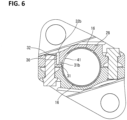
- Crank pin bearing portion 11 is fitted to crank pin 5 via a pair of semicylindrical bearing metals 16 (see FIG. 5 and FIG. 6 ).
- Crank pin 5 is provided with, in the inside thereof, a lubrication oil passage to which pressurized lubricating oil is supplied, and a distal end portion of the lubrication oil passage extending in the radial direction is opened to the outer peripheral surface of crank pin 5 as an oil supply hole 29 (see FIG. 1 ).
- an oil hole 30 is formed through crank pin bearing portion 11, and when oil hole 30 meets oil supply hole 29 on the crank pin 5 side, lubricating oil is injected from oil hole 30 as oil jet.
- Combustion load acts on upper-pin pin boss portion 12 from upper link 3 via upper pin 4, and lower link 6 swings with control pin 9 as a fulcrum so as to transmit force to crank pin 5 by motion like leverage. Consequently, the combustion load acts on upper-pin pin boss portion 12 in the lower direction in FIG. 1 and combustion reaction force acts on control-pin pin boss portion 13 in the lower direction in FIG. 1 similarly.
- reaction force from crank pin 5 acts on the vicinity of the center of crank pin bearing portion 11 in the upper direction in FIG. 1 , and consequently, a large stress is generated around crank pin bearing portion 11 of lower link upper 6A.
- crank pin bearing portion 11 becomes maximum in an area in a direction from the center of crank pin 5 toward piston 1, more specifically, in an area in a direction slightly close to upper pin 4. On the other hand, in an area close to divided surface 14 of crank pin bearing portion 11, stress becomes relatively small.
- FIG. 4 there is shown a sectional view of lower link upper 6A (sectional view along a surface orthogonal to the axial direction of crank pin 5) in which an oil hole 30 in a first embodiment is provided to crank pin bearing portion 11.
- Oil hole 30 is formed to lubricate the connecting portion of upper link 3 connected to lower link 6 in upper-pin pin boss portion 12, namely, the sliding surface between upper link 4 and upper link 3, and is formed in a substantially L shape by a first oil hole 31 and a second oil hole 32.
- First oil hole 31 is a non-through hole (that is, a distal end 31a is sealed) linearly extending from an inner peripheral surface 11a of crank pin bearing portion 11 outwardly in the radial direction, and the base end is opened to inner peripheral surface 11a of crank pin bearing portion 11 as an oil inlet 31b.
- first oil hole 31 is obliquely inclined with respect to divided surface 14, and is formed along the radial line of crank pin bearing portion 11. In this way, by arranging first oil hole 31 along the radial line of crank pin bearing portion 11, oil inlet 31b is opened in a form of substantially true circle.
- first oil hole 31 (for example, an inclination angle ⁇ of first oil hole 31 with divided surface 14 set as a reference) in lower link 6 is set so as to be relatively small, to avoid being positioned in an area where stress is high in the above-mentioned circumferential distribution of stress of crankpin pin bearing portion 11.
- inclination angle ⁇ of first oil hole 31 with divided surface 14 set as a reference is 10°.
- first oil hole 31 is formed such that the extension line of the center line of first oil hole 31 extends in a direction not intersecting the outer peripheral surface of upper pin 4. Specifically, the extension line of the center line of first oil hole 31 passes through the lower side of upper pin 4 (opposite side of piston 1).
- Second oil hole 32 is a non-through hole (that is, a distal end 32a is sealed) linearly extending from the outer surface of lower link 6 to the inside of lower link 6. Specifically, it extends from a bottom surface 17a of a groove portion 17 facing upper pin 4 to the inside of lower link 6, and the base end of second oil hole 32 is opened to bottom surface 17a as an oil outlet 32b.
- the distal end portion of second oil hole 32 that is, a portion on the distal end 32a side
- first oil hole 31 that is, a portion on the distal end 31a side
- Second oil hole 32 is formed such that the extension line of the center line of second oil hole 32 extends in a direction intersecting the outer peripheral surface of upper pin 4, and, in the illustration, it is directed to the vicinity of the center of upper pin 4.
- second oil hole 32 extends along the direction orthogonal to divided surface 14, so as to be parallel to the center axial line of bolt 21 adjacent thereto and screw hole 24 corresponding to bolt 21. In this way, since second oil hole 32 extends parallel to screw hole 24 adjacent thereto, the thickness therebetween is fixed in the axial direction, and it is possible to suppress the occurrence of partial thinning and partially lowering of strength.
- First oil hole 31 and second oil hole 32 are formed along one plane orthogonal to the axial direction of crank pin 5.
- first oil hole 31 and second oil hole 32 are positioned on the plane passing through the middle of the dimension in the axial direction of crank pin bearing portion 11.
- first and second oil holes 31 and 32 may be formed in an oblique direction so as to have angles to the plane slightly, it is desirable to formed them along the plane in order to secure the strength in oil inlet 31b of first oil hole 31 .
- first oil hole 31 and second oil hole 32 intersecting each other is larger than 90°.
- inclination angle ⁇ of first oil hole 31 with divided surface 14 set as a reference is 10°
- second oil hole 32 intersects first oil hole 31 at the angle of 100°.
- first oil hole 31 intersects second oil hole 32 at an obtuse angle, and consequently, the loss of flow of lubricating oil at the intersection becomes small.
- First oil hole 31 and second oil hole 32 are each formed, for example, by secondary machining with a drill after forming lower link upper 6A by forging.
- carburization treatment (carburization quench hardening) is conducted to lower link upper 6A for increasing surface hardness, it is desirable to perform drilling before the carburization treatment.
- the diameter of second oil hole 32 is set to be larger than that of first oil hole 31.
- the rigidity around second oil hole 32 is lowered, and a relatively large deformation occurs, as a result of which stress around first oil hole 31 (in particular, around oil inlet 31b of first oil hole 31) where stress concentration as the largest problem arises is lowered. That is, as compared with case where the diameter of first oil hole 31 is the same as that of second oil hole 32, or case where the diameter of first oil hole 31 is smaller than that of second oil hole 32, stress at oil inlet 31b is alleviated.
- distal end 32a of second oil hole 32 passes through and slightly extends from first oil hole 31 further due to drilling, such an excess passage part is not necessary if working can be performed.
- oil supply hole 29 on the crank pin 5 side meets oil inlet 31b of first oil hole 31, and, as oil jet, pressurized lubricating oil is injected from oil outlet 32b toward upper pin 4 through first oil hole 31 and second oil hole 32.
- oil jet pressurized lubricating oil is injected from oil outlet 32b toward upper pin 4 through first oil hole 31 and second oil hole 32.
- inclination angle ⁇ of first oil hole 31 with respect to divided surface 14 is relatively small and oil inlet 31b is opened at a position close to divided surface 14, the stress concentration at the opening edge of oil inlet 31b is alleviated.
- inclination angle ⁇ with respect to divided surface 14 would be approximately 40°. In this angle direction, the oil hole passes through an area where stress is high in the stress distribution in the circumferential direction of crank pin bearing portion 11.
- oil inlet 31b is located at a position close to divided surface 14, and it is advantages in suppressing stress concentration.
- a communicating hole 41 of bearing metal 16 is formed in a long hole shape which is circumferentially long.
- bearing metal 16 is formed by being divided into two parts by 180° so as to have a cylindrical shape as a whole, and they are assembled to respective lower link upper 6A and lower link lower 6B in a non-rotation state.
- Bearing metal 16 is formed with communicating hole 41 located at a position corresponding to inlet 31b, in order to communicate oil supply hole 29 on the crank pin 5 side and oil inlet 31b of lower link 6 with each other.
- communicating hole 41 has a long hole shape extending in the circumferential direction. Accordingly, oil supply hole 29 on the crank pin 5 side and oil inlet 31b of lower link 6 are kept in a communication state over a predetermined angle range. In other words, the time during which oil supply hole 29 on the crank pin 5 side and oil hole 31b of lower link 6 communicate with each other becomes long. Consequently, a sufficient amount of lubricating oil can be secured.
- one end of communicating hole 41 having a long hole shape is located at a position corresponding to oil inlet 31b, and the other end extends to a position at which inclination angle ⁇ with divided surface 14 set as a reference becomes larger.
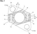
- FIG. 7 to FIG. 9 show lower link 6 in a second embodiment in which inclination angle ⁇ of first oil hole 31 along the radial line of crank pin bearing portion 11 is set, for example, to 24°.
- First oil hole 31 is also formed such that the extension line of the center line of first oil hole 31 is directed in a direction not intersecting upper pin 4, and lubricating oil is guided toward the upper pin 4 side via second oil hole 32.
- the intersecting angle at the intersection portion between first oil hole 31 and second oil hole 32 is larger than that of the first embodiment, and pressure loss caused by a change in a flow direction is small.
- the passage length of second oil hole 32 becomes shorter than that in the first embodiment, as a result of which pressure loss also becomes small.
- oil inlet 31b of first oil hole 31 is positioned close to the area where stress is high. It is therefore preferable to set inclination angle ⁇ while considering these matters.
- communicating hole 41 of bearing metal 16 is also formed in a long hole shape
- inclination angle ⁇ of first oil hole 31 is large as compared with the first embodiment, and oil inlet 31b of first oil hole 31 is positioned in the vicinity of the middle in the circumferential direction of communicating hole 41 having a long hole shape (see FIG. 9 ).
- lower link upper 6A (lower link 6) of the first embodiment and the second embodiment is provided with, in addition to oil hole 30, an oil hole 28 for supplying oil jet toward piston 1 (see FIG. 1 ) or the inner wall surface of a cylinder.
- Oil hole 28 is positioned closer to control pin 9 than the position at which the maximum combustion load reaction in the circumference of crank pin bearing portion 11 acts. Consequently, the stress concentration at the opening edge of oil hole 28 by the combustion load and combustion load reaction mentioned above is relatively small. Oil hole 28 is therefore formed so as to simply extend linearly.
- An communicating hole 42 of bearing metal 16 which corresponds to oil hole 28 is formed in a true circle (see FIG. 5 , FIG. 6 and FIG. 9 ).
- first oil hole 31 is formed along the radial line of crank pin bearing portion 11, it may be slightly inclined with respect to the radial line of crank pin bearing portion 11 or may be arranged so as to be slightly displaced in parallel with respect to the radial line.
- second oil hole 32 may not be accurately arranged along the direction orthogonal to divided surface 14 (that is, the direction parallel to bolt 21).
Landscapes
- Engineering & Computer Science (AREA)
- Mechanical Engineering (AREA)
- General Engineering & Computer Science (AREA)
- Chemical & Material Sciences (AREA)
- Combustion & Propulsion (AREA)
- Shafts, Cranks, Connecting Bars, And Related Bearings (AREA)
- Lubrication Of Internal Combustion Engines (AREA)
Applications Claiming Priority (1)
| Application Number | Priority Date | Filing Date | Title |
|---|---|---|---|
| PCT/IB2020/000771 WO2022058766A1 (ja) | 2020-09-15 | 2020-09-15 | 内燃機関ロアリンク |
Publications (3)
| Publication Number | Publication Date |
|---|---|
| EP4215724A1 EP4215724A1 (en) | 2023-07-26 |
| EP4215724A4 EP4215724A4 (en) | 2023-11-01 |
| EP4215724B1 true EP4215724B1 (en) | 2025-03-05 |
Family
ID=80776637
Family Applications (1)
| Application Number | Title | Priority Date | Filing Date |
|---|---|---|---|
| EP20954022.8A Active EP4215724B1 (en) | 2020-09-15 | 2020-09-15 | Lower link of internal combustion engine |
Country Status (5)
| Country | Link |
|---|---|
| US (1) | US11994046B2 (https=) |
| EP (1) | EP4215724B1 (https=) |
| JP (1) | JP7338796B2 (https=) |
| CN (1) | CN116034215B (https=) |
| WO (1) | WO2022058766A1 (https=) |
Family Cites Families (10)
| Publication number | Priority date | Publication date | Assignee | Title |
|---|---|---|---|---|
| JP4646879B2 (ja) * | 2006-09-08 | 2011-03-09 | 本田技研工業株式会社 | ストローク特性可変エンジン |
| JP5298911B2 (ja) * | 2009-02-12 | 2013-09-25 | 日産自動車株式会社 | 内燃機関の複リンク式ピストンクランク機構 |
| US20120111143A1 (en) * | 2009-07-17 | 2012-05-10 | Nissan Motor Co., Ltd. | Crankshaft of internal combustion engine provided with multi link-type piston-crank mechanism and multi link-type piston-crank mechanism of internal combustion engine |
| JP6036006B2 (ja) * | 2012-08-24 | 2016-11-30 | 日産自動車株式会社 | 内燃機関の複リンク式ピストン−クランク機構の潤滑構造 |
| BR112016003572B1 (pt) | 2013-08-22 | 2021-09-14 | Nissan Motor Co. Ltd | Mecanismo de manivela de pistão de ligação dupla para motor de combustão interna |
| US10273841B2 (en) * | 2014-09-17 | 2019-04-30 | Nissan Motor Co., Ltd. | Internal combustion engine |
| WO2017037935A1 (ja) * | 2015-09-04 | 2017-03-09 | 日産自動車株式会社 | 内燃機関のピストンクランク機構におけるアッパピンの潤滑構造および潤滑方法 |
| JP6132057B2 (ja) * | 2016-06-27 | 2017-05-24 | 日産自動車株式会社 | 内燃機関の複リンク式ピストン−クランク機構の潤滑構造 |
| MX2020007290A (es) * | 2018-01-31 | 2020-09-10 | Nissan Motor | Componente de acoplamiento con orificio de aceite. |
| JP6961514B2 (ja) | 2018-02-28 | 2021-11-05 | 日産自動車株式会社 | 内燃機関の複リンク式ピストンクランク機構 |
-
2020
- 2020-09-15 US US18/026,307 patent/US11994046B2/en active Active
- 2020-09-15 JP JP2022550046A patent/JP7338796B2/ja active Active
- 2020-09-15 CN CN202080105133.9A patent/CN116034215B/zh active Active
- 2020-09-15 EP EP20954022.8A patent/EP4215724B1/en active Active
- 2020-09-15 WO PCT/IB2020/000771 patent/WO2022058766A1/ja not_active Ceased
Also Published As
| Publication number | Publication date |
|---|---|
| US11994046B2 (en) | 2024-05-28 |
| CN116034215B (zh) | 2026-01-02 |
| EP4215724A4 (en) | 2023-11-01 |
| WO2022058766A1 (ja) | 2022-03-24 |
| CN116034215A (zh) | 2023-04-28 |
| JP7338796B2 (ja) | 2023-09-05 |
| JPWO2022058766A1 (https=) | 2022-03-24 |
| EP4215724A1 (en) | 2023-07-26 |
| US20240035401A1 (en) | 2024-02-01 |
Similar Documents
| Publication | Publication Date | Title |
|---|---|---|
| EP2463498B1 (en) | Multi-link piston-crank mechanism | |
| JP3882643B2 (ja) | 内燃機関の可変圧縮比機構 | |
| JP5298911B2 (ja) | 内燃機関の複リンク式ピストンクランク機構 | |
| EP1835146B1 (en) | Piston crank mechanism | |
| EP3037642B1 (en) | Double-link piston crank mechanism for internal combustion engine | |
| US8826882B2 (en) | Lubricating structure of multi-link piston-crank mechanism for internal combustion engine | |
| JP6132057B2 (ja) | 内燃機関の複リンク式ピストン−クランク機構の潤滑構造 | |
| EP1801387A1 (en) | Lower link for piston crank mechanism of internal combustion engine | |
| JP5577913B2 (ja) | リンク機構の連結ピン軸受構造 | |
| JP5810675B2 (ja) | 内燃機関の複リンク式ピストン−クランク機構 | |
| JP5251576B2 (ja) | 内燃機関の複リンク式ピストンクランク機構 | |
| EP4215724B1 (en) | Lower link of internal combustion engine | |
| JP2008208783A (ja) | リンク機構の軸受構造 | |
| JP5205991B2 (ja) | リンク機構の軸受構造 | |
| JP7335195B2 (ja) | 内燃機関のロアリンク | |
| JP2013032853A (ja) | リンク機構の軸受構造 | |
| JP2014194208A (ja) | 可変圧縮比内燃機関の潤滑構造 | |
| JP5321148B2 (ja) | 複リンク式可変圧縮比内燃機関 | |
| JP2006241980A (ja) | カムシャフトのエンドピースおよびカムシャフト | |
| JP2007231886A (ja) | 内燃機関のピストンクランク機構におけるロアリンク |
Legal Events
| Date | Code | Title | Description |
|---|---|---|---|
| STAA | Information on the status of an ep patent application or granted ep patent |
Free format text: STATUS: THE INTERNATIONAL PUBLICATION HAS BEEN MADE |
|
| PUAI | Public reference made under article 153(3) epc to a published international application that has entered the european phase |
Free format text: ORIGINAL CODE: 0009012 |
|
| STAA | Information on the status of an ep patent application or granted ep patent |
Free format text: STATUS: REQUEST FOR EXAMINATION WAS MADE |
|
| 17P | Request for examination filed |
Effective date: 20230321 |
|
| AK | Designated contracting states |
Kind code of ref document: A1 Designated state(s): AL AT BE BG CH CY CZ DE DK EE ES FI FR GB GR HR HU IE IS IT LI LT LU LV MC MK MT NL NO PL PT RO RS SE SI SK SM TR |
|
| A4 | Supplementary search report drawn up and despatched |
Effective date: 20230928 |
|
| RIC1 | Information provided on ipc code assigned before grant |
Ipc: F02B 75/32 20060101ALI20230922BHEP Ipc: F02B 75/04 20060101ALI20230922BHEP Ipc: F01M 1/06 20060101AFI20230922BHEP |
|
| DAV | Request for validation of the european patent (deleted) | ||
| DAX | Request for extension of the european patent (deleted) | ||
| GRAP | Despatch of communication of intention to grant a patent |
Free format text: ORIGINAL CODE: EPIDOSNIGR1 |
|
| STAA | Information on the status of an ep patent application or granted ep patent |
Free format text: STATUS: GRANT OF PATENT IS INTENDED |
|
| GRAS | Grant fee paid |
Free format text: ORIGINAL CODE: EPIDOSNIGR3 |
|
| INTG | Intention to grant announced |
Effective date: 20250103 |
|
| GRAA | (expected) grant |
Free format text: ORIGINAL CODE: 0009210 |
|
| STAA | Information on the status of an ep patent application or granted ep patent |
Free format text: STATUS: THE PATENT HAS BEEN GRANTED |
|
| AK | Designated contracting states |
Kind code of ref document: B1 Designated state(s): AL AT BE BG CH CY CZ DE DK EE ES FI FR GB GR HR HU IE IS IT LI LT LU LV MC MK MT NL NO PL PT RO RS SE SI SK SM TR |
|
| REG | Reference to a national code |
Ref country code: GB Ref legal event code: FG4D |
|
| REG | Reference to a national code |
Ref country code: CH Ref legal event code: EP |
|
| REG | Reference to a national code |
Ref country code: DE Ref legal event code: R096 Ref document number: 602020047463 Country of ref document: DE |
|
| REG | Reference to a national code |
Ref country code: IE Ref legal event code: FG4D |
|
| PG25 | Lapsed in a contracting state [announced via postgrant information from national office to epo] |
Ref country code: RS Free format text: LAPSE BECAUSE OF FAILURE TO SUBMIT A TRANSLATION OF THE DESCRIPTION OR TO PAY THE FEE WITHIN THE PRESCRIBED TIME-LIMIT Effective date: 20250605 |
|
| PG25 | Lapsed in a contracting state [announced via postgrant information from national office to epo] |
Ref country code: FI Free format text: LAPSE BECAUSE OF FAILURE TO SUBMIT A TRANSLATION OF THE DESCRIPTION OR TO PAY THE FEE WITHIN THE PRESCRIBED TIME-LIMIT Effective date: 20250305 |
|
| REG | Reference to a national code |
Ref country code: NL Ref legal event code: MP Effective date: 20250305 |
|
| PG25 | Lapsed in a contracting state [announced via postgrant information from national office to epo] |
Ref country code: ES Free format text: LAPSE BECAUSE OF FAILURE TO SUBMIT A TRANSLATION OF THE DESCRIPTION OR TO PAY THE FEE WITHIN THE PRESCRIBED TIME-LIMIT Effective date: 20250305 |
|
| REG | Reference to a national code |
Ref country code: LT Ref legal event code: MG9D |
|
| PG25 | Lapsed in a contracting state [announced via postgrant information from national office to epo] |
Ref country code: NO Free format text: LAPSE BECAUSE OF FAILURE TO SUBMIT A TRANSLATION OF THE DESCRIPTION OR TO PAY THE FEE WITHIN THE PRESCRIBED TIME-LIMIT Effective date: 20250605 |
|
| PG25 | Lapsed in a contracting state [announced via postgrant information from national office to epo] |
Ref country code: HR Free format text: LAPSE BECAUSE OF FAILURE TO SUBMIT A TRANSLATION OF THE DESCRIPTION OR TO PAY THE FEE WITHIN THE PRESCRIBED TIME-LIMIT Effective date: 20250305 |
|
| PG25 | Lapsed in a contracting state [announced via postgrant information from national office to epo] |
Ref country code: LV Free format text: LAPSE BECAUSE OF FAILURE TO SUBMIT A TRANSLATION OF THE DESCRIPTION OR TO PAY THE FEE WITHIN THE PRESCRIBED TIME-LIMIT Effective date: 20250305 |
|
| PG25 | Lapsed in a contracting state [announced via postgrant information from national office to epo] |
Ref country code: GR Free format text: LAPSE BECAUSE OF FAILURE TO SUBMIT A TRANSLATION OF THE DESCRIPTION OR TO PAY THE FEE WITHIN THE PRESCRIBED TIME-LIMIT Effective date: 20250606 Ref country code: BG Free format text: LAPSE BECAUSE OF FAILURE TO SUBMIT A TRANSLATION OF THE DESCRIPTION OR TO PAY THE FEE WITHIN THE PRESCRIBED TIME-LIMIT Effective date: 20250305 |
|
| REG | Reference to a national code |
Ref country code: AT Ref legal event code: MK05 Ref document number: 1773106 Country of ref document: AT Kind code of ref document: T Effective date: 20250305 |
|
| PG25 | Lapsed in a contracting state [announced via postgrant information from national office to epo] |
Ref country code: NL Free format text: LAPSE BECAUSE OF FAILURE TO SUBMIT A TRANSLATION OF THE DESCRIPTION OR TO PAY THE FEE WITHIN THE PRESCRIBED TIME-LIMIT Effective date: 20250305 |
|
| PG25 | Lapsed in a contracting state [announced via postgrant information from national office to epo] |
Ref country code: SE Free format text: LAPSE BECAUSE OF FAILURE TO SUBMIT A TRANSLATION OF THE DESCRIPTION OR TO PAY THE FEE WITHIN THE PRESCRIBED TIME-LIMIT Effective date: 20250305 |
|
| PG25 | Lapsed in a contracting state [announced via postgrant information from national office to epo] |
Ref country code: SM Free format text: LAPSE BECAUSE OF FAILURE TO SUBMIT A TRANSLATION OF THE DESCRIPTION OR TO PAY THE FEE WITHIN THE PRESCRIBED TIME-LIMIT Effective date: 20250305 |
|
| PG25 | Lapsed in a contracting state [announced via postgrant information from national office to epo] |
Ref country code: PT Free format text: LAPSE BECAUSE OF FAILURE TO SUBMIT A TRANSLATION OF THE DESCRIPTION OR TO PAY THE FEE WITHIN THE PRESCRIBED TIME-LIMIT Effective date: 20250707 |
|
| PG25 | Lapsed in a contracting state [announced via postgrant information from national office to epo] |
Ref country code: IT Free format text: LAPSE BECAUSE OF FAILURE TO SUBMIT A TRANSLATION OF THE DESCRIPTION OR TO PAY THE FEE WITHIN THE PRESCRIBED TIME-LIMIT Effective date: 20250305 Ref country code: PL Free format text: LAPSE BECAUSE OF FAILURE TO SUBMIT A TRANSLATION OF THE DESCRIPTION OR TO PAY THE FEE WITHIN THE PRESCRIBED TIME-LIMIT Effective date: 20250305 |
|
| PG25 | Lapsed in a contracting state [announced via postgrant information from national office to epo] |
Ref country code: AT Free format text: LAPSE BECAUSE OF FAILURE TO SUBMIT A TRANSLATION OF THE DESCRIPTION OR TO PAY THE FEE WITHIN THE PRESCRIBED TIME-LIMIT Effective date: 20250305 |
|
| PGFP | Annual fee paid to national office [announced via postgrant information from national office to epo] |
Ref country code: FR Payment date: 20250929 Year of fee payment: 6 |
|
| PG25 | Lapsed in a contracting state [announced via postgrant information from national office to epo] |
Ref country code: CZ Free format text: LAPSE BECAUSE OF FAILURE TO SUBMIT A TRANSLATION OF THE DESCRIPTION OR TO PAY THE FEE WITHIN THE PRESCRIBED TIME-LIMIT Effective date: 20250305 Ref country code: EE Free format text: LAPSE BECAUSE OF FAILURE TO SUBMIT A TRANSLATION OF THE DESCRIPTION OR TO PAY THE FEE WITHIN THE PRESCRIBED TIME-LIMIT Effective date: 20250305 |
|
| PG25 | Lapsed in a contracting state [announced via postgrant information from national office to epo] |
Ref country code: RO Free format text: LAPSE BECAUSE OF FAILURE TO SUBMIT A TRANSLATION OF THE DESCRIPTION OR TO PAY THE FEE WITHIN THE PRESCRIBED TIME-LIMIT Effective date: 20250305 |
|
| PG25 | Lapsed in a contracting state [announced via postgrant information from national office to epo] |
Ref country code: SK Free format text: LAPSE BECAUSE OF FAILURE TO SUBMIT A TRANSLATION OF THE DESCRIPTION OR TO PAY THE FEE WITHIN THE PRESCRIBED TIME-LIMIT Effective date: 20250305 |
|
| PG25 | Lapsed in a contracting state [announced via postgrant information from national office to epo] |
Ref country code: IS Free format text: LAPSE BECAUSE OF FAILURE TO SUBMIT A TRANSLATION OF THE DESCRIPTION OR TO PAY THE FEE WITHIN THE PRESCRIBED TIME-LIMIT Effective date: 20250705 |
|
| REG | Reference to a national code |
Ref country code: DE Ref legal event code: R097 Ref document number: 602020047463 Country of ref document: DE |
|
| PGFP | Annual fee paid to national office [announced via postgrant information from national office to epo] |
Ref country code: DE Payment date: 20250925 Year of fee payment: 6 |
|
| PGFP | Annual fee paid to national office [announced via postgrant information from national office to epo] |
Ref country code: GB Payment date: 20251024 Year of fee payment: 6 |
|
| PLBE | No opposition filed within time limit |
Free format text: ORIGINAL CODE: 0009261 |
|
| STAA | Information on the status of an ep patent application or granted ep patent |
Free format text: STATUS: NO OPPOSITION FILED WITHIN TIME LIMIT |
|
| PG25 | Lapsed in a contracting state [announced via postgrant information from national office to epo] |
Ref country code: DK Free format text: LAPSE BECAUSE OF FAILURE TO SUBMIT A TRANSLATION OF THE DESCRIPTION OR TO PAY THE FEE WITHIN THE PRESCRIBED TIME-LIMIT Effective date: 20250305 |
|
| REG | Reference to a national code |
Ref country code: CH Ref legal event code: L10 Free format text: ST27 STATUS EVENT CODE: U-0-0-L10-L00 (AS PROVIDED BY THE NATIONAL OFFICE) Effective date: 20260114 |
|
| 26N | No opposition filed |
Effective date: 20251208 |