EP4212223A1 - Hybride vergnügungsrutsche - Google Patents
Hybride vergnügungsrutsche Download PDFInfo
- Publication number
- EP4212223A1 EP4212223A1 EP22151168.6A EP22151168A EP4212223A1 EP 4212223 A1 EP4212223 A1 EP 4212223A1 EP 22151168 A EP22151168 A EP 22151168A EP 4212223 A1 EP4212223 A1 EP 4212223A1
- Authority
- EP
- European Patent Office
- Prior art keywords
- user
- hybrid
- slide
- section
- amusement slide
- Prior art date
- Legal status (The legal status is an assumption and is not a legal conclusion. Google has not performed a legal analysis and makes no representation as to the accuracy of the status listed.)
- Pending
Links
- 238000012986 modification Methods 0.000 description 19
- 230000004048 modification Effects 0.000 description 19
- 230000007704 transition Effects 0.000 description 8
- XLYOFNOQVPJJNP-UHFFFAOYSA-N water Substances O XLYOFNOQVPJJNP-UHFFFAOYSA-N 0.000 description 6
- 230000005484 gravity Effects 0.000 description 3
- 238000005096 rolling process Methods 0.000 description 3
- 230000035807 sensation Effects 0.000 description 3
- 230000001174 ascending effect Effects 0.000 description 2
- 206010048744 Fear of falling Diseases 0.000 description 1
- 238000013459 approach Methods 0.000 description 1
- 238000013016 damping Methods 0.000 description 1
- 230000007423 decrease Effects 0.000 description 1
- 230000003247 decreasing effect Effects 0.000 description 1
- 230000001419 dependent effect Effects 0.000 description 1
- 238000011161 development Methods 0.000 description 1
- 230000018109 developmental process Effects 0.000 description 1
- 239000000463 material Substances 0.000 description 1
- 238000011144 upstream manufacturing Methods 0.000 description 1
Images


Classifications
-
- A—HUMAN NECESSITIES
- A63—SPORTS; GAMES; AMUSEMENTS
- A63G—MERRY-GO-ROUNDS; SWINGS; ROCKING-HORSES; CHUTES; SWITCHBACKS; SIMILAR DEVICES FOR PUBLIC AMUSEMENT
- A63G21/00—Chutes; Helter-skelters
- A63G21/22—Suspended slideways
-
- A—HUMAN NECESSITIES
- A63—SPORTS; GAMES; AMUSEMENTS
- A63G—MERRY-GO-ROUNDS; SWINGS; ROCKING-HORSES; CHUTES; SWITCHBACKS; SIMILAR DEVICES FOR PUBLIC AMUSEMENT
- A63G21/00—Chutes; Helter-skelters
- A63G21/02—Chutes; Helter-skelters without rails
-
- A—HUMAN NECESSITIES
- A63—SPORTS; GAMES; AMUSEMENTS
- A63G—MERRY-GO-ROUNDS; SWINGS; ROCKING-HORSES; CHUTES; SWITCHBACKS; SIMILAR DEVICES FOR PUBLIC AMUSEMENT
- A63G21/00—Chutes; Helter-skelters
- A63G21/16—Chutes; Helter-skelters with forced removal of the passenger from the seat
-
- A—HUMAN NECESSITIES
- A63—SPORTS; GAMES; AMUSEMENTS
- A63G—MERRY-GO-ROUNDS; SWINGS; ROCKING-HORSES; CHUTES; SWITCHBACKS; SIMILAR DEVICES FOR PUBLIC AMUSEMENT
- A63G21/00—Chutes; Helter-skelters
- A63G21/18—Water-chutes
-
- A—HUMAN NECESSITIES
- A63—SPORTS; GAMES; AMUSEMENTS
- A63G—MERRY-GO-ROUNDS; SWINGS; ROCKING-HORSES; CHUTES; SWITCHBACKS; SIMILAR DEVICES FOR PUBLIC AMUSEMENT
- A63G21/00—Chutes; Helter-skelters
- A63G21/20—Slideways with movably suspended cars, or with cars moving on ropes, or the like
Definitions
- Attachment means are used as means which attach the user to the running gear.
- the attachment means can include the harness or the vehicle and any components connecting the running gear and the harness or the vehicle.
- the attachment means can be understood as a part of the vehicle.
- the running gear might be understood as a part of the vehicle.
- the advantage of the hybrid amusement slide according to the present invention is the enhanced experience for the user because the combination of the sliding trail and the gliding system enables movement paths which are not possible with one of the two components alone.
- the movement path has at least one of the sliding trail and the gliding system.
- One design of the hybrid amusement slide involves that the user first slides on the sliding trail while being suspended by the gliding system. The sliding trail then ends and the user is then only held by the gliding system. Then the user is released from the gliding system and the gliding system also ends.
- the hybrid amusement slide is configured such that the user can disengage from the gliding system. Once the user is disengaged from the gliding system, he is only supported by the sliding trail from below.
- the hybrid amusement slide further comprises a drive system configured to drive the user.
- the drive system can be part of the sliding trail, of the gliding system or a combination thereof.
- the drive system generates water jets or an (electro)magnetic field acting on the vehicle which accommodates the user.
- the drive system acts on the running gear to which the user is attached.
- the track switch can be part of the sliding trail, of the gliding system or of a combination of both. If the track switch is part of the gliding system, this means that the guide means splits into two or more sub-means.
- the movement path has a section in which the sliding trail splits into a left part and a right part.
- the gliding system does not comprise a track switch in this section, such that the user remains attached to the guide means and follows either the left or the right part of the sliding trail. It is also possible to disengage the user from the gliding system before the sliding trail splits.
- the sliding trail does not comprise a track switch, but the gliding system has a track switch, such that there is a section of the movement path having two or more guide means to one of which the user can be attached.
- one of the guide means maintains its vertical distance to the sliding trail, while the other guide means increases its vertical distance from the sliding trail, thus raising the user and giving the experience of a jump.
- both the sliding trail and the gliding system include a track switch, resulting in two or more potentially independent movement sub-paths in this section.
- the hybrid amusement slide comprises a control system for controlling the track switch.
- the control system receives user input by the user to control the track switch. The user input can be given before the user starts its slide or during the slide.
- the hybrid amusement slide comprises a vehicle for accommodating the user.
- the vehicle can be connected to the running gear which runs, rolls or glides on or in the guide means, for example via attachment means.
- the vehicle can for example a boat, a raft, a ring, a mat or a sack.
- the vehicle comprises the running gear for running along the guide means.
- the running gear can also run on the outside of the guide means.
- the guide means can or cannot have a hollow core.
- the vehicle comprises a contact part configured to be in contact with the sliding trail and being releasable from the rest of the vehicle.
- the rest of the vehicle might include a seat for accommodating the user.
- the contact part can for example be a ring.
- the contact part When the contact part is released from the rest of the vehicle, the user remains accommodated by the rest of the vehicle and for example remains suspended by the gliding system through the rest of the vehicle. However, the contact part separates from the rest of the vehicle, thus giving the user the impression that the vehicle is broken or a part of the vehicle got loose.
- the sliding trail ends, such that the contact part releases from the rest of the vehicle and falls down while the user remains suspended by the gliding system.
- the hybrid amusement slide comprises a harness for accommodating the user.
- the harness comprises an arrangement of straps or ropes and at least one locking device, like a carabiner, to ensure that it does not detach from the user unintentionally.
- An example is a five point harness.
- the harness can comprise the running gear.
- the harness comprises a hook and the gliding system comprises a rope as the guide means to which the hook of the harness is engageable.
- the hook glides along the rope to suspend the user from above.
- the hook is an example of the running gear.
- the harness comprises a running gear comprising one or more wheels rolling on or in the guide means.
- the hybrid amusement slide does, along the movement path, first comprise a section with a guide means only and then a section with a sliding trail only as explained above.
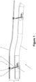
- Figure 1 shows a schematic side view of a hybrid amusement slide 1.
- the hybrid amusement slide is also simply referred to as slide 1.
- Figure 2 shows a schematic sectional view of the slide 1 of Figure 1 .
- the slide 1 comprises a sliding trail 2 for supporting the user U from below.
- the sliding trail 2 can be a body slide or a slide used with a vehicle, such as a ring, a boat, a mat or a sack.
- the vehicle is a ring 7.
- the sliding trail 2 can be a dry slide or a water slide in which a film of water propagates along the sliding trail 2 to reduce friction.
- the sliding trail 2 typically utilizes gravity to accelerate the user U while sliding.
- the slide 1 further comprises a gliding system 3 including guide means 4 for suspending the user U from above.
- the guide means 4 is a pipe or tube for guiding a running gear 5.
- the running gear 5 comprises a plurality of wheels 5a to roll along the guide means 4.
- the gliding system 3 comprises attachment means 6 for attaching the user U to the running gear 5.
- the attachment means 6 comprises a seat 6a for accommodating the user. Not shown in the Figures is an optional restraint system for securing the user U in the seat 6a.
- the bottom of the seat 6a rests in the ring 7, which is intended to slide along the sliding trail 2. It shall be noted that the ring 4 is optional and the seat 6a could be intended for gliding on the sliding trail 2.
- the sliding trail 2 has a U-shaped cross section to accommodate the user U, for example via the ring 4.
- the shape of the sliding trail 2 enables a lateral movement of the user U depending on the forces acting during the slide.
- Figure 2 further indicates a vertical direction v and a horizontal direction h. Those directions are defined relative to the sliding trail 2.
- the horizontal direction h is parallel to the bottom of the sliding trail 2 and perpendicular to the sliding direction of the user U.
- the vertical direction is perpendicular to the bottom of the sliding trail 2, and is thus perpendicular to both the horizontal direction h and the sliding direction of the user U.
- a vertical distance d between the sliding trail 2 and the guide means 3 is given in the vertical direction and determines whether the user U is supported only from below via the sliding trail 2, only suspended from above via the gliding system 3 or a combination of both.
- the guide means 4 typically runs parallel to the sliding trail 2. For example, it is located centrally above the sliding trail 2 in the horizontal direction h.
- the hybrid amusement slide 1 defines a movement path of the user U from a first point to a second point. If the hybrid amusement slide 1 is a pure gravity slide, the first point is higher than the second point and the movement path typically continuously descends from the first to the second point.
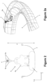
- Figure 2a shows a perspective view onto a hybrid amusement slide 1.
- Figure 2a shows the guide means 4 located centrally above the sliding trail 2.
- the movement path of the user U makes a righthand curve. This causes centrifugal forces acting on the user U, the ring 7 and the attachment means 6 in the horizontal direction h. Those forces let the user U swing up the left wall of the sliding trail 2.
- the gliding system 3 enables this movement, for example by enabling a rotation of the running gear 5 about the guide means 4 or a rotation of the attachment means 6 relative to the running gear 5.
- Figure 3 shows a modification of the slide 1 of Figure 1 .
- the part of the movement path of the slide 1 shown in Figure 3 is divided into three sections S1, S2 and S3.
- the user U is supported by the sliding trail 2 from below and is suspended by the gliding system 3 from above.
- section S2 there is no sliding trail 2 for supporting the user U from below and the user U is only suspended by the gliding system 3.
- the sliding trail 2 descends downwards such that the vertical distance h between the sliding trail 2 and the guide means 4 increases.
- the user U thus loses contact to the sliding trail 2 and hovers by use of the gliding system 3.
- the sliding trail 2 sets in again, with a short part having an ascending slope to smoothly accept the user U on the sliding trail 2.
- the vertical distance between the guide means 4 and the sliding trail 2 increases at the transition from section S2 to section S3.
- the user U is again both supported by the sliding trail 2 from below and suspended from above via the gliding system 3.
- the ring 4 stays attached to the attachment means 6 such that the ring is in contact with the sliding trail 2 both in section S1 and section S3.
- the ring 4 detaches from the attachment means 6 in the transition from section S1 to section S2. This increases the sensation experienced by the user U.
- the attachment means 6 are in contact with the sliding trail 2.
- the ring 4 is also optional in section S1. In this case, no ring is present and the seat 6a is in contact with the sliding trail 2 both in section S1 and section S3.
- the slope of the guide means 4 in section S2 is larger than in sections S1 and S3. This gives the user U the impression of dropping in section S2.
- section S1 of the slide 1 can be omitted, which means that the movement path starts with the gliding system 3 only, not having a sliding trail 2 for supporting the user U from below. However, the transition from section S2 to S3 remains.
- Figure 4 shows a modification of the modification shown in Figure 3 .
- both the sliding trail 2 and the gliding system 3 are present in section S4, only the gliding system 3 is present in section S5 and there is a transition between sections S4 and S5.
- section S6 does not contain a sliding trail 2, but rather a brake run 8 for braking the user U at the end of the slide.
- the ring 7 detaches from the attachment means 6 in section S5 as described above. In another implementation, the ring 7 is not present at all as described above, which means that already in section S4 the attachment means 6 are in contact with the sliding trail 2.
- Figure 5 shows another modification of the hybrid amusement slide 1.
- Sections S7 and S8 correspond to sections S1 and S2 shown in Figure 3 .
- the ring 7 detaches from the attachment means 6.
- section S9 another ring 7 is waiting for the user U accommodated by the attachment means 6, in particular the seat 6a.
- the attachment means 6 engage with the new ring 7 at the transition from section S8 to section S9 and the slide continues with the new ring 7.
- vehicle transport means which collect the vehicle, in the present example the ring 7, detached from the attachment means 6 in section S8 and transporting the collected ring 7 to the transition from section S8 to section S9.
- Figure 6 shows another modification of the hybrid amusement slide 1.
- the movement path has section S10 and a section S11, wherein section S10 corresponds to section S2 of Figure 2 or section S8 of Figure 5 .
- Section S11 corresponds to section S3 of Figure 3 or section S9 of Figure 5 , but comprises an uphill section having an ascending slope. This means that the movement path of the hybrid amusement slide 1 moves upwards in the uphill section.
- the user U can accomplish the uphill section based on remaining kinetic energy or there can be a drive system for delivering additional energy to the user U in the uphill section.
- the drive system can act on the running gear 5, the attachment means 6, the ring 7 or a combination thereof.
- the ring 7 is not present. This means that, in section S11, the attachment means 6a are in contact with the sliding trail 2.
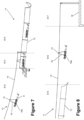
- Figure 7 shows another embodiment of a hybrid amusement slide 11.
- the slide 11 comprises a sliding trail 12 similar to the sliding trail 2 of the previous embodiment and a gliding system 13 comprising a rope 14 as the guide means and a harness 16a for accommodating the user U.
- the harness 16a is attached to a running gear 15, which runs along the rope 14, via the attachment means 16.
- the part of the movement path of the slide 11 shown in Figure 7 has three sections S12, S13 and S14.
- section S12 only the gliding system 13, but not the sliding trail 12 is present.
- the user U slides or glides along the rope 14 only.
- section S13 both the sliding trail 12 and the gliding system 13 are present.
- the vertical distance between the rope 14 and the sliding trail 12 gradually decreases until the user U is in contact with the sliding trail 12.
- the user U is both supported from below by the sliding trail 12 and suspended from above by the gliding system 13.
- the harness 16a detaches from the attachment means 16 such that, in section S14 of the movement path of the slide 11, the user U is only supported from below by the sliding trail 12.
- the rope 14 ends shortly after the harness 16a is detached from the attachment means 16.
- the harness 16a might remain attached to the attachment means 16, and thus to the guide means 14, in section 14, such that the user U is supported from below and suspended from above in this section.
- the running gear 15 can have at least one wheel for rolling along the rope 14, at least one gliding surface for gliding along the rope 14 or a combination thereof.
- Figure 8 shows a modification of the slide 11 of Figure 7 in terms of other sections S15, S16 and S17 of the movement path of the hybrid amusement slide 11.
- section S15 both the sliding trail 12 and the gliding system 13 are present, such that the user U is both supported from below and suspended from above.
- section S16 only the gliding system 13 is present, but not the sliding trail 12, such that the user is only suspended from above in section S16.
- Section S17 is a brake section in which, like in section S16, only the gliding system 13 is present, but not the sliding trail 12.
- the user U is slowed down in a brake run 18, in particular to a complete stop, for example by braking the running gear 15.
- the attachment means 16 are detached from the running gear 15 or the harness 16a is detached from the attachment means 16, such that the user U can leave the hybrid amusement slide 11.
- Figure 10 shows a third embodiment of a hybrid amusement slide 21 comprising a sliding trail 22 and a gliding system 23.
- the gliding system 23 comprises a rope 24, a running gear 25 gliding or rolling along the rope 24, attachment means 26 connected to the running gear 25 and a harness 26a attached to the attachment means 26.
- the user U is attached to the harness 26a and rests on a ring 27 as an embodiment of the vehicle.
- the movement path of the slide 21 shown in Figure 10 has three sections S18, S19 and S20.
- section S18 the gliding system 23 is present, but not the sliding trail 22.
- section S19 both the sliding trail 22 and the gliding system 23 are present.
- section S20 only the sliding trail S22 is present, but not the gliding system 23.
- section S18 the user U slides along the rope 24 suspended from above.
- section S19 the sliding trail S22 sets in, for example with a decreasing vertical distance d between the sliding trail 22 and the rope 24.
- section S19 the ring 27 starts to get in contact with the sliding trail 22.
- section S19 the ring 27 detaches from the attachment means 26 and the rope 24 ends.
- the user U then proceeds to section S20 where he slides along the sliding trail 22 on the ring 27.
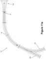
- Figure 11a shows a top view of a gliding system 33.
- the guide means of the gliding system 33 is a hollow tube 34 in which a running gear 35 can glide or roll. At its lower end pointing towards the sliding trail, the tube 34 has a slit through which the running gear 35 can be connected to the attachment means.
- the pipe 34 has a funnel-shaped opening 34a at which the running gear 35 can inter into the hollow core of the tube 34.
- the pipe 34 has an optional track switch at which the tube diverts into a first tube 34b and a second tube 34c.
- the track switch comprises diverting means (not shown) which determine into which of the tubes 34b and 34c the running gear 35 moves at the track switch.
- the diverting means can be driven by a drive system controlled by a control system of the hybrid amusement slide.
- the setting of the diverting means can be controlled randomly, in a predetermined pattern or set by the user, either before starting the slide or during the slide.
- Figure 11b shows a perspective view onto the gliding system 33.
- the funnel-shaped opening 34a of the tube 34 can be identified in more detail.
- Figure 11c shows a sectional view of the tube 34.
- the running gear 35 comprises a spherical member gliding inside the hollow core of the tube 34.
- a part of the inner surface of the tube 34 which comes into contact with the running gear 35 has an anti-friction surface to enable smooth gliding of the running gear 35 inside the tube 34.
- the longitudinal slit can be seen through which the running gear 35 extends towards the outside of the tube 34.
- the attachment means are connected to the part of the running gear 35 which protrudes through the longitudinal slit to the outside.
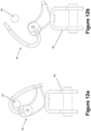
- FIG 12a shows another example of a gliding system 43 in a first state.
- the gliding system 43 comprises a rope 44, a running gear 45 for gliding along the rope 44 and attachment means 46 attached to the running gear 45.
- the running gear 45 is a hook shown in its closed state in Figure 12a . In this state, the running gear 45 is securely attached to the rope 44.
- Figure 12b shows another state of the gliding system 43 of Figure 12a in which the hook of the running gear 45 is released and opens by means of the weight of the running gear 45, the attachment means 46 or a user being held by the attachment means 46.
- Figure 13 shows another example of a hybrid amusement slide 51.
- the slide 51 comprises a sliding trail 52 and a gliding system 53.
- the gliding system 53 comprises a rope 54, a running gear 55 and attachment means 56.
- the running gear 55 is a loop wound about the rope 54 and connected to the attachment means 56.
- the attachment means 56 can be a non-bendable or rigid member, such as a pipe or a rod.
- a ring 57 for accommodating the user U is attached to the attachment means 56.
- the gliding system might enable a rocking or swinging movement of the user about an axis perpendicular to the guide means.
- the rocking or swinging movement is in particular back and forth. This can be achieved by an articulated joint, for example between the running gear and the attachment means.
- the swinging or rocking movement is enabled by the running gear 35, 45, 55 pivoting about or inside the guide means.
Landscapes
- Electric Propulsion And Braking For Vehicles (AREA)
Priority Applications (1)
| Application Number | Priority Date | Filing Date | Title |
|---|---|---|---|
| EP22151168.6A EP4212223A1 (de) | 2022-01-12 | 2022-01-12 | Hybride vergnügungsrutsche |
Applications Claiming Priority (1)
| Application Number | Priority Date | Filing Date | Title |
|---|---|---|---|
| EP22151168.6A EP4212223A1 (de) | 2022-01-12 | 2022-01-12 | Hybride vergnügungsrutsche |
Publications (1)
| Publication Number | Publication Date |
|---|---|
| EP4212223A1 true EP4212223A1 (de) | 2023-07-19 |
Family
ID=79317190
Family Applications (1)
| Application Number | Title | Priority Date | Filing Date |
|---|---|---|---|
| EP22151168.6A Pending EP4212223A1 (de) | 2022-01-12 | 2022-01-12 | Hybride vergnügungsrutsche |
Country Status (1)
| Country | Link |
|---|---|
| EP (1) | EP4212223A1 (de) |
Citations (6)
| Publication number | Priority date | Publication date | Assignee | Title |
|---|---|---|---|---|
| US5853331A (en) * | 1998-05-06 | 1998-12-29 | Bungee Japan, Inc. | Amusement ride |
| NL1009494C2 (nl) * | 1998-06-25 | 2000-01-04 | Caripro Holding B V | Amusementsinrichting alsmede werkwijze voor het bedienen van een dergelijke amusementsinrichting. |
| US20160361660A1 (en) * | 2014-12-11 | 2016-12-15 | Buttercup Business, Inc. | High Angle Tethered Slide with Freefall Drop and Variable Radius Swing |
| US20200108324A1 (en) * | 2018-10-05 | 2020-04-09 | Universal City Studios Llc | Hybrid ride vehicle systems and methods |
| WO2021094005A1 (de) * | 2019-11-15 | 2021-05-20 | Mack Rides Gmbh & Co. Kg | Fahrgeschäft, insbesondere wasserfahrgeschäft, sowie verfahren zum betreiben eines solchen fahrgeschäfts |
| WO2021262104A1 (en) * | 2020-06-23 | 2021-12-30 | Polin Su Parklari Ve Havuz Sistemleri Anonim Sirketi | A waterslide with a zip line |
-
2022
- 2022-01-12 EP EP22151168.6A patent/EP4212223A1/de active Pending
Patent Citations (6)
| Publication number | Priority date | Publication date | Assignee | Title |
|---|---|---|---|---|
| US5853331A (en) * | 1998-05-06 | 1998-12-29 | Bungee Japan, Inc. | Amusement ride |
| NL1009494C2 (nl) * | 1998-06-25 | 2000-01-04 | Caripro Holding B V | Amusementsinrichting alsmede werkwijze voor het bedienen van een dergelijke amusementsinrichting. |
| US20160361660A1 (en) * | 2014-12-11 | 2016-12-15 | Buttercup Business, Inc. | High Angle Tethered Slide with Freefall Drop and Variable Radius Swing |
| US20200108324A1 (en) * | 2018-10-05 | 2020-04-09 | Universal City Studios Llc | Hybrid ride vehicle systems and methods |
| WO2021094005A1 (de) * | 2019-11-15 | 2021-05-20 | Mack Rides Gmbh & Co. Kg | Fahrgeschäft, insbesondere wasserfahrgeschäft, sowie verfahren zum betreiben eines solchen fahrgeschäfts |
| WO2021262104A1 (en) * | 2020-06-23 | 2021-12-30 | Polin Su Parklari Ve Havuz Sistemleri Anonim Sirketi | A waterslide with a zip line |
Similar Documents
| Publication | Publication Date | Title |
|---|---|---|
| EP3577354B1 (de) | Karabiner mit doppelverriegelung | |
| US10046745B2 (en) | Cable-traversing trolley adapted for use with impact braking | |
| US10246105B2 (en) | Multidirectional transport system | |
| US8499696B2 (en) | Cable transport system | |
| EP0656801B1 (de) | Vergnügungsanlage | |
| US5853331A (en) | Amusement ride | |
| EP1391227A1 (de) | Seilrutsche mit statisch vorgespanntem Seil | |
| US20090255436A1 (en) | Ricky braking system for zipline riders | |
| US20090078148A1 (en) | Suspended coaster rail apparatus and method | |
| US10376798B2 (en) | High angle tethered slide with freefall drop and variable radius swing | |
| US5660113A (en) | Aerial cable support system for snow ski jumping | |
| KR20200083602A (ko) | 트롤리 시스템과 연관된 레일들 및 선로들 | |
| JP2004505738A (ja) | 乗車して落下する娯楽用装置 | |
| EP4212223A1 (de) | Hybride vergnügungsrutsche | |
| KR102281015B1 (ko) | 짚라인 트롤리 | |
| KR101571367B1 (ko) | 낙하형 레포츠 체험장치 | |
| US20050288109A1 (en) | Fun-ride and a method for the operation of a fun-ride | |
| CN100402112C (zh) | 高层建筑的降落伞援救系统 | |
| CN112601591B (zh) | 用于水滑道的加速段 | |
| KR20210073406A (ko) | 병렬삭도를 이용한 다인승 활강놀이기구 | |
| JPH1133238A (ja) | 滑走飛行遊戯装置 | |
| KR102252844B1 (ko) | 공중활강이동장치용 주행기의 활강속도 감속장치 | |
| KR102252838B1 (ko) | 안전도착 유도를 위한 보조 감속장치가 구비된 공중활강이동장치 | |
| EP1389148A1 (de) | Fahrgeschäft | |
| CN106422155A (zh) | 热气球蹦极安全装备系统 |
Legal Events
| Date | Code | Title | Description |
|---|---|---|---|
| PUAI | Public reference made under article 153(3) epc to a published international application that has entered the european phase |
Free format text: ORIGINAL CODE: 0009012 |
|
| STAA | Information on the status of an ep patent application or granted ep patent |
Free format text: STATUS: THE APPLICATION HAS BEEN PUBLISHED |
|
| AK | Designated contracting states |
Kind code of ref document: A1 Designated state(s): AL AT BE BG CH CY CZ DE DK EE ES FI FR GB GR HR HU IE IS IT LI LT LU LV MC MK MT NL NO PL PT RO RS SE SI SK SM TR |
|
| STAA | Information on the status of an ep patent application or granted ep patent |
Free format text: STATUS: THE APPLICATION IS DEEMED TO BE WITHDRAWN |