EP4211367B1 - Oberwellenreduzierungsvorrichtung und industrieroboter - Google Patents
Oberwellenreduzierungsvorrichtung und industrieroboter Download PDFInfo
- Publication number
- EP4211367B1 EP4211367B1 EP20952699.5A EP20952699A EP4211367B1 EP 4211367 B1 EP4211367 B1 EP 4211367B1 EP 20952699 A EP20952699 A EP 20952699A EP 4211367 B1 EP4211367 B1 EP 4211367B1
- Authority
- EP
- European Patent Office
- Prior art keywords
- harmonic reducer
- shaft
- sealing
- hole
- cavity
- Prior art date
- Legal status (The legal status is an assumption and is not a legal conclusion. Google has not performed a legal analysis and makes no representation as to the accuracy of the status listed.)
- Active
Links
Images






Classifications
-
- F—MECHANICAL ENGINEERING; LIGHTING; HEATING; WEAPONS; BLASTING
- F16—ENGINEERING ELEMENTS AND UNITS; GENERAL MEASURES FOR PRODUCING AND MAINTAINING EFFECTIVE FUNCTIONING OF MACHINES OR INSTALLATIONS; THERMAL INSULATION IN GENERAL
- F16H—GEARING
- F16H57/00—General details of gearing
- F16H57/02—Gearboxes; Mounting gearing therein
- F16H57/027—Gearboxes; Mounting gearing therein characterised by means for venting gearboxes, e.g. air breathers
-
- B—PERFORMING OPERATIONS; TRANSPORTING
- B25—HAND TOOLS; PORTABLE POWER-DRIVEN TOOLS; MANIPULATORS
- B25J—MANIPULATORS; CHAMBERS PROVIDED WITH MANIPULATION DEVICES
- B25J9/00—Program-controlled manipulators
- B25J9/10—Program-controlled manipulators characterised by positioning means for manipulator elements
- B25J9/102—Gears specially adapted therefor, e.g. reduction gears
- B25J9/1025—Harmonic drives
-
- F—MECHANICAL ENGINEERING; LIGHTING; HEATING; WEAPONS; BLASTING
- F16—ENGINEERING ELEMENTS AND UNITS; GENERAL MEASURES FOR PRODUCING AND MAINTAINING EFFECTIVE FUNCTIONING OF MACHINES OR INSTALLATIONS; THERMAL INSULATION IN GENERAL
- F16H—GEARING
- F16H19/00—Gearings comprising essentially only toothed gears or friction members and not capable of conveying indefinitely-continuing rotary motion
- F16H19/08—Gearings comprising essentially only toothed gears or friction members and not capable of conveying indefinitely-continuing rotary motion for interconverting rotary motion and oscillating motion
-
- F—MECHANICAL ENGINEERING; LIGHTING; HEATING; WEAPONS; BLASTING
- F16—ENGINEERING ELEMENTS AND UNITS; GENERAL MEASURES FOR PRODUCING AND MAINTAINING EFFECTIVE FUNCTIONING OF MACHINES OR INSTALLATIONS; THERMAL INSULATION IN GENERAL
- F16H—GEARING
- F16H49/00—Other gearings
- F16H49/001—Wave gearings, e.g. harmonic drive transmissions
-
- F—MECHANICAL ENGINEERING; LIGHTING; HEATING; WEAPONS; BLASTING
- F16—ENGINEERING ELEMENTS AND UNITS; GENERAL MEASURES FOR PRODUCING AND MAINTAINING EFFECTIVE FUNCTIONING OF MACHINES OR INSTALLATIONS; THERMAL INSULATION IN GENERAL
- F16H—GEARING
- F16H57/00—General details of gearing
- F16H57/02—Gearboxes; Mounting gearing therein
- F16H57/029—Gearboxes; Mounting gearing therein characterised by means for sealing the gearboxes, e.g. to improve airtightness
-
- F—MECHANICAL ENGINEERING; LIGHTING; HEATING; WEAPONS; BLASTING
- F16—ENGINEERING ELEMENTS AND UNITS; GENERAL MEASURES FOR PRODUCING AND MAINTAINING EFFECTIVE FUNCTIONING OF MACHINES OR INSTALLATIONS; THERMAL INSULATION IN GENERAL
- F16H—GEARING
- F16H57/00—General details of gearing
- F16H57/04—Features relating to lubrication or cooling or heating
- F16H57/042—Guidance of lubricant
- F16H57/043—Guidance of lubricant within rotary parts, e.g. axial channels or radial openings in shafts
-
- F—MECHANICAL ENGINEERING; LIGHTING; HEATING; WEAPONS; BLASTING
- F16—ENGINEERING ELEMENTS AND UNITS; GENERAL MEASURES FOR PRODUCING AND MAINTAINING EFFECTIVE FUNCTIONING OF MACHINES OR INSTALLATIONS; THERMAL INSULATION IN GENERAL
- F16H—GEARING
- F16H57/00—General details of gearing
- F16H57/04—Features relating to lubrication or cooling or heating
- F16H57/045—Lubricant storage reservoirs, e.g. reservoirs in addition to a gear sump for collecting lubricant in the upper part of a gear case
- F16H57/0454—Sealings between different partitions of a gearing or to a reservoir
-
- F—MECHANICAL ENGINEERING; LIGHTING; HEATING; WEAPONS; BLASTING
- F16—ENGINEERING ELEMENTS AND UNITS; GENERAL MEASURES FOR PRODUCING AND MAINTAINING EFFECTIVE FUNCTIONING OF MACHINES OR INSTALLATIONS; THERMAL INSULATION IN GENERAL
- F16H—GEARING
- F16H19/00—Gearings comprising essentially only toothed gears or friction members and not capable of conveying indefinitely-continuing rotary motion
- F16H19/08—Gearings comprising essentially only toothed gears or friction members and not capable of conveying indefinitely-continuing rotary motion for interconverting rotary motion and oscillating motion
- F16H2019/085—Gearings comprising essentially only toothed gears or friction members and not capable of conveying indefinitely-continuing rotary motion for interconverting rotary motion and oscillating motion by using flexible members
-
- Y—GENERAL TAGGING OF NEW TECHNOLOGICAL DEVELOPMENTS; GENERAL TAGGING OF CROSS-SECTIONAL TECHNOLOGIES SPANNING OVER SEVERAL SECTIONS OF THE IPC; TECHNICAL SUBJECTS COVERED BY FORMER USPC CROSS-REFERENCE ART COLLECTIONS [XRACs] AND DIGESTS
- Y02—TECHNOLOGIES OR APPLICATIONS FOR MITIGATION OR ADAPTATION AGAINST CLIMATE CHANGE
- Y02P—CLIMATE CHANGE MITIGATION TECHNOLOGIES IN THE PRODUCTION OR PROCESSING OF GOODS
- Y02P70/00—Climate change mitigation technologies in the production process for final industrial or consumer products
- Y02P70/10—Greenhouse gas [GHG] capture, material saving, heat recovery or other energy efficient measures, e.g. motor control, characterised by manufacturing processes, e.g. for rolling metal or metal working
Definitions
- Embodiments of the present invention generally relate to the field of reducers, and more particularly, to a harmonic reducer and an industrial robot.
- Harmonic reducers are widely used for driving various devices or machines, such as industrial robots, electric tools, automobiles and the like, due to small size, light weight and high precision thereof.
- a conventional harmonic reducer includes three basic components, i.e., a flexible spline, a circular spline, and a wave generator.
- the wave generator may be rotated so as to cause the flexible spline to produce controllable elastic deformation and mesh with the circular spline. In this way, the harmonic reducer may achieve the transferring of motion and power.
- Lubricant is typically provided inside the harmonic reducer so as to reduce the friction between various components of the harmonic reducer.
- a high pressure may be built up in an internal space of the harmonic reducer due to various causes, such as temperature rising and vaporization of the lubricant caused by the temperature rising.
- the internal pressure buildup may cause the lubricant to leak out of the harmonic reducer through oil seals of the harmonic reducer.
- the leakage of the lubricant would degrade the lubricating performance of the harmonic reducer and contaminate the robot and work objects processed by the robot.
- various example embodiments of the present disclosure provide a harmonic reducer that can prevent both internal pressure buildup and lubricant leakage.
- the sealing mechanism comprises: a base element coupled to the first end of the shaft and comprising a second through hole in fluid communication with the first through hole; a first sealing element arranged on the base element and comprising one or more openings and a sealing surface surrounding the one or more openings, the one or more openings being configured to communicate the cavity with the second through hole; and a second sealing element arranged between the first sealing element and the base element, and comprising an elastic sealing lip configured to contact the sealing surface of the first sealing element to block the communication between the cavity and the second through hole when the internal pressure of the cavity is below a pressure threshold and configured to be pushed away from the sealing surface of the first sealing element to communicate the cavity with the second through hole when the internal pressure of the cavity is above the pressure threshold.
- the base element comprises: a mounting part inserted into the first through hole at the first end of the shaft, the second through hole being provided on the mounting part; and a receiving part comprising a first receiving space, a second receiving space, and a step between the first receiving space and the second receiving space, the second receiving space being closer to the mounting part than the first receiving space.
- the first sealing element further comprises: a sealing part arranged in the first receiving space and supported by the step, the one or more openings and the sealing surface being provided on the sealing part; and a mounting pillar coupled to the sealing part and configured to mount the second sealing element.
- the second sealing element further comprises: a supporting part configured to support the elastic sealing lip and comprising a mounting hole into which the mounting pillar of the first sealing element is inserted.
- the base element further comprises a groove at its outer surface.
- the sealing mechanism comprises: a second sealing element arranged at the second end of the shaft and comprising an elastic sealing lip configured to contact the second end of the shaft to block the communication between the first through hole and the external environment when the internal pressure of the cavity is below a pressure threshold and configured to be pushed away from the second end of the shaft to communicate the first through hole with the external environment when the internal pressure of the cavity is above the pressure threshold.
- the second sealing element further comprises: a supporting part configured to support the elastic sealing lip and comprising a mounting hole.
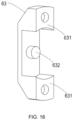
- the harmonic reducer further comprises a pulley arranged on the shaft near to the second end of the shaft and being rotatable together with the shaft, wherein the sealing mechanism further comprises a second base element configured to support the second sealing element and comprising: a pair of mounting parts coupled to the pulley; and a second mounting pillar inserted into the mounting hole of the second sealing element to fix the supporting part of the second sealing element.
- the harmonic reducer further comprises one or more channels arranged between the one of the first and second flanges and corresponding one of the first and second bearings.
- the harmonic reducer further comprises a bearing sleeve arranged around the corresponding one of the first and second bearings.
- example embodiments of the present disclosure provide an industrial robot comprising a harmonic reducer according to the first aspect of the present disclosure.
- a sealing mechanism is provided in the harmonic reducer so as to selectively allow the cavity to be in fluid communication with the external environment via the first through hole.
- the sealing mechanism When the internal pressure of the cavity is below the pressure threshold, the sealing mechanism would block the communication between the cavity and the external environment. When the internal pressure of the cavity is above the pressure threshold, the sealing mechanism would allow the cavity to be in communication with the external environment. In this way, the internal pressure of the harmonic reducer could be maintained at a low level.
- the lubricant may be further prevented from leaking out of the harmonic reducer via the first through hole of the shaft.
- the sealing mechanism could prevent debris in the external environment from entering the harmonic reducer via the first through hole.
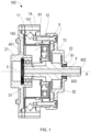
- the first flange 21 is coupled to the shaft 4 via a first bearing 31.
- the second flange 22 is coupled to the shaft 4 via a second bearing 32.
- the shaft 4 may be supported by the first flange 21 and the second flange 22.
- the first flange 21 is further coupled to the flexible spline 11 and the second flange 22 is further coupled to the circular spline 12.
- the flexible spline 11 may rotate in synchronization with the first flange 21 at a low speed, and the circular spline 12 and the second flange 22 would not rotate.
- the first end 401 of the shaft 4 is arranged inside the harmonic reducer 100 and near to the first flange 21.
- a cavity 5 is provided between the first flange 21 and the first end 401 of the shaft 4.
- the cavity 5 is in fluid communication with internal spaces 9 of the harmonic reducer 100 via for example gaps on the first bearing 31.
- the cavity 5 and the internal spaces 9 of the harmonic reducer 100 may be at substantially the same pressure.
- the cavity 5 is in fluid communication with the external environment via the first through hole 403. If the pressure inside the harmonic reducer 100 is increased due to for example the temperature rising, the gas inside the harmonic reducer 100 may be released into the external environment via the first through hole 403.
- lubricant is typically provided in the internal spaces 9 of the harmonic reducer 100.
- the gas in the internal spaces 9 may be released into the cavity 5 and then into the external environment via the first through hole 403, such that the pressure of the internal spaces 9 could be maintained at a low level. In this way, the lubricant leakage via oil seals 81 of the harmonic reducer 100 could be prevented effectively.
- the harmonic reducer 100 further includes a cross roller bearing 14.
- the cross roller bearing 14 includes an outer ring 141 coupled to the flexible spline 11 and an inner ring 142 coupled to the circular spline 12.
- the cross roller bearing 14 may be replaced by other types of bearings. The scope of the present invention is not intended to be limited in this respect.
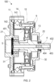
- Fig. 2 illustrates a cross-sectional view of a harmonic reducer in accordance with a second embodiment of the present disclosure.
- the construction of the harmonic reducer 100 as shown in Fig. 2 is similar to that of the harmonic reducer 100 as shown in Fig. 1 , except that the harmonic reducer 100 as shown in Fig. 2 further includes a porous material 404 arranged in the first through hole 403.
- the porous material 404 is permeable to the gas and non-permeable to the lubricant.
- the porous material 404 may adsorb the lubricant mixed in the gas from the cavity 5 on one hand, and may prevent debris in the external environment from entering the cavity 5 via the first through hole 403 on the other hand.
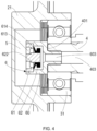
- Fig. 3 illustrates a cross-sectional view of a harmonic reducer in accordance with a third embodiment of the present disclosure.
- the construction of the harmonic reducer 100 as shown in Fig. 3 is similar to that of the harmonic reducer 100 as shown in Fig. 1 , except that the harmonic reducer 100 as shown in Fig. 3 further includes a sealing mechanism 6.
- the sealing mechanism 6 is configured to selectively allow the cavity 5 to be in fluid communication with the external environment in accordance with an internal pressure of the cavity 5.
- the sealing mechanism 6 may allow the cavity 5 to be in communication with the external environment.
- the sealing mechanism 6 may block the communication between the cavity 5 and the external environment.
- the base element 60 is arranged at the first end 401 of the shaft 4 and adapted to support the first and second sealing elements 61, 62.
- the base element 60 may be detachably mounted onto the shaft 4, for example through screws or in other manners.
- the base element 60 may be soldered on the first end 401 of the shaft 4 or even formed as a part of the shaft 4.
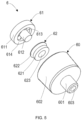
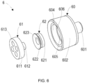
- the base element 60 includes a mounting part 601 adapted to be mounted onto the shaft 4 and a receiving part 602 adapted to receive the first and second sealing elements 61, 62.
- the mounting part 601 is provided with a second through hole 603 in fluid communication with the first through hole 403.
- the mounting part 601 may be inserted into the first through hole 403 of the shaft 4, and coupled to the shaft 4 through screws or interference fit, or in various other manners.
- the receiving part 602 includes a first receiving space 604, a second receiving space 605, and a step 606 between the first receiving space 604 and the second receiving space 605.
- the second receiving space 605 is in fluid communication with the second through hole 603, and in turn, in fluid communication with the first through hole 403.
- the second receiving space 605 is closer to the mounting part 601 than the first receiving space 604. That is, the second receiving space 605 is disposed at a lower portion of the receiving part 602, and the first receiving space 604 is disposed at an upper portion of the receiving part 602.
- the first and second sealing elements 61, 62 are arranged in the first and second receiving spaces 604, 605, as will be described in detail hereinafter.
- the first sealing element 61 is arranged on the base element 60 and includes one or more openings 613 and a sealing surface 614 surrounding the one or more openings 613.
- the one or more openings 613 are configured to communicate the cavity 5 with the second through hole 603.
- the sealing surface 614 is configured to cooperate with the second sealing element 62. When the sealing surface 614 is in contact with the second sealing element 62, the one or more openings 613 would be closed, and when the sealing surface 614 is not in contact with the second sealing element 62, the one or more openings 613 would be opened.
- the second sealing element 62 is arranged between the first sealing element 61 and the base element 60 so as to selectively allow or block the fluid communication between the cavity 5 and the first through hole 403 of the shaft 4.
- the second sealing element 62 is generally located in the second receiving space 605.
- the second sealing element 62 includes an elastic sealing lip 622.
- Fig. 7 illustrates a cross-sectional view of a harmonic reducer in accordance with a fourth embodiment of the present disclosure.
- the construction of the harmonic reducer 100 as shown in Fig. 7 is similar to that of the harmonic reducer 100 as shown in Fig. 3 , except that the base element 60 further includes a groove 607 at its outer surface.
- Figs. 8 and 9 illustrate details of the groove 607.
- the groove 607 is arranged at an outer surface of the receiving part 602 of the base element 60.
- the groove 607 includes a bottom surface and two oblique sidewalls. The oblique sidewalls of the groove 607 would cause the lubricant adhered on the base element 60 to fly away from the base element 60 more easily.
- a large amount of lubricant would probably accumulate in the cavity 5.
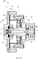
- one or more channels may be provided between the cavity 5 and the internal spaces 9.
- Figs. 11-13 illustrate an example approach for removing the lubricant in the cavity 5.
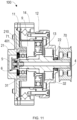
- Fig. 11 illustrates a cross-sectional view of a harmonic reducer in accordance with a sixth embodiment of the present disclosure
- Fig. 12 is a perspective view of the first flange of the harmonic reducer as shown in Fig. 11
- Fig. 13 illustrates a relative arrangement between the first flange and the first bearing of the harmonic reducer as shown in Fig. 11
- the construction of the harmonic reducer 100 as shown in Fig. 11 is similar to that of the harmonic reducer 100 as shown in Fig. 10 , except that the harmonic reducer 100 further includes one or more channels 210 arranged between the first flange 21 and the first bearing 31. Through the channels 210, the lubricant in the cavity 5 may flow back into the internal spaces 9.
- the harmonic reducer 100 further includes a bearing sleeve 71 arranged around the first bearing 31.
- the bearing sleeve 71 may protect the first bearing 31 from being worn by the first flange 21.
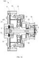
- the harmonic reducer 100 further includes a third base element 72 arranged at the first end 401 of the shaft 4.
- the construction of the third base element 72 is similar to that of the base element 60 as shown in Fig. 7 . It is to be understood that in other embodiments, the third base element 72 may be removed, as that shown in Figs. 1 and 2 .
- the harmonic reducer 100 may be used in various devices or machines, such as industrial robots, electric tools, and automobiles.
- the harmonic reducer 100 may be used for driving a joint of an industrial robot.
Landscapes
- Engineering & Computer Science (AREA)
- General Engineering & Computer Science (AREA)
- Mechanical Engineering (AREA)
- Robotics (AREA)
- General Details Of Gearings (AREA)
- Manipulator (AREA)
- Retarders (AREA)
Claims (15)
- Oberwellen-Reduzierer (100), umfassend:ein Schaft (4), umfassend ein erstes Durchgangsloch (403), das sich von einem ersten Ende (401) zu einem zweiten Ende (402) des Schafts (4) in einer axialen Richtung (X) des Schafts (4) erstreckt;einen Wellengenerator (13), der auf dem Schaft (4) angeordnet ist und zusammen mit dem Schaft (4) drehbar ist;eine flexible Kerbverzahnung (11), die um den Wellengenerator (13) herum angeordnet ist;eine kreisförmige Kerbverzahnung (12), die um die flexible Kerbverzahnung (11) herum angeordnet ist; dadurch gekennzeichnet, dassein erster Flansch (21) über ein erstes Lager (31) mit dem Schaft (4) gekoppelt ist und mit der flexiblen Kerbverzahnung (11) gekoppelt ist; undein zweiter Flansch (22) über ein zweites Lager (32) mit dem Schaft (4) gekoppelt ist und mit der kreisförmigen Kerbverzahnung (12) gekoppelt ist,wobei einer der ersten und zweiten Flansche (21, 22) in der Nähe des ersten Endes (401) des Schafts (4) angeordnet ist, undwobei zwischen dem einen des ersten oder zweiten Flansches (21, 22) und dem ersten Ende (401) des Schafts (4) ein Hohlraum (5) vorgesehen ist, der über das erste Durchgangsloch (403) in Fluidverbindung mit einer äußeren Umgebung steht.
- Oberwellen-Reduzierer (100) gemäß Anspruch 1, der ferner ein poröses Material (404) umfasst, das in dem ersten Durchgangsloch (403) angeordnet ist.
- Oberwellen-Reduzierer (100) gemäß Anspruch 1, der ferner einen Dichtungsmechanismus (6) umfasst, der so konfiguriert ist, dass er es dem Hohlraum (5) selektiv ermöglicht, über das erste Durchgangsloch (403) in Fluidverbindung mit der äußeren Umgebung zu stehen, und zwar in Übereinstimmung mit einem Innendruck des Hohlraums (5).
- Oberwellen-Reduzierer (100) gemäß Anspruch 3, wobei der Dichtungsmechanismus (6) umfasst:ein Basiselement (60), das mit dem ersten Ende (401) des Schafts (4) verbunden ist und ein zweites Durchgangsloch (603) aufweist, das in Fluidverbindung mit dem ersten Durchgangsloch (403) steht;ein erstes Dichtungselement (61), das auf dem Basiselement (60) angeordnet ist und eine oder mehrere Öffnungen (613) und eine Dichtungsfläche (614) umfasst, die die eine oder mehreren Öffnungen (613) umgibt, wobei die eine oder mehreren Öffnungen (613) so konfiguriert sind, dass sie den Hohlraum (5) mit dem zweiten Durchgangsloch (603) verbinden; undein zweites Dichtungselement (62), das zwischen dem ersten Dichtungselement (61) und dem Basiselement (60) angeordnet ist und eine elastische Dichtlippe (622) umfasst, die so konfiguriert ist, dass sie die Dichtfläche (614) des ersten Dichtelements (61) berührt, um die Verbindung zwischen dem Hohlraum (5) und dem zweiten Durchgangsloch (603) zu blockieren, wenn der Innendruck des Hohlraums (5) unter einem Druckschwellenwert liegt, und so konfiguriert ist, dass sie von der Dichtfläche (614) des ersten Dichtelements (61) weggedrückt wird, um den Hohlraum (5) mit dem zweiten Durchgangsloch (603) zu verbinden, wenn der Innendruck des Hohlraums (5) über dem Druckschwellenwert liegt.
- Oberwellen-Reduzierer (100) nach Anspruch 4, wobei das Basiselement (60) umfasst:ein Montageteil (601), das in das erste Durchgangsloch (403) am ersten Ende (401) des Schafts (4) eingesetzt ist, wobei das zweite Durchgangsloch (603) am Montageteil (601) vorgesehen ist; undein Aufnahmeteil (602), das einen ersten Aufnahmeraum (604), einen zweiten Aufnahmeraum (605) und eine Stufe (606) zwischen dem ersten Aufnahmeraum (604) und dem zweiten Aufnahmeraum (605) umfasst, wobei der zweite Aufnahmeraum (605) näher am Montageteil (601) liegt als der erste Aufnahmeraum (604).
- Oberwellen-Reduzierer (100) gemäß Anspruch 5, wobei das erste Dichtungselement (61) ferner umfasst:ein Dichtungsteil (611), das in dem ersten Aufnahmeraum (604) angeordnet ist und von der Stufe (606) getragen wird, wobei die eine oder mehreren Öffnungen (613) und die Dichtungsfläche (614) an dem Dichtungsteil (611) vorgesehen sind; undeine Montagesäule (612), die mit dem Dichtungsteil (611) verbunden ist und so konfiguriert ist, dass sie das zweite Dichtungselement (62) befestigt.
- Oberwellen-Reduzierer (100) gemäß Anspruch 6, wobei das zweite Dichtungselement (62) ferner umfasst:
ein Stützteil (621), das so konfiguriert ist, dass es die elastische Dichtlippe (622) stützt, und das ein Montageloch (623) umfasst, in das die Montagesäule (612) des ersten Dichtelements (61) eingesetzt wird. - Oberwellen-Reduzierer (100) gemäß Anspruch 4, wobei das Basiselement (60) ferner eine Nut (607) an seiner Außenfläche umfasst.
- Oberwellen-Reduzierer (100) gemäß Anspruch 3, wobei der Dichtungsmechanismus (6) umfasst:
ein zweites Dichtungselement (62), das am zweiten Ende (402) des Schaft (4) angeordnet ist und eine elastische Dichtlippe (622) umfasst, die so konfiguriert ist, dass sie das zweite Ende (402) des Schafs (4) berührt, um die Verbindung zwischen dem ersten Durchgangsloch (403) und der äußeren Umgebung zu blockieren, wenn der Innendruck des Hohlraums (5) unter einem Druckschwellenwert liegt, und so konfiguriert ist, dass sie vom zweiten Ende (402) des Schafts (4) weggedrückt wird, um das erste Durchgangsloch (403) mit der äußeren Umgebung zu verbinden, wenn der Innendruck des Hohlraums (5) über dem Druckschwellenwert liegt. - Oberwellen-Reduzierer (100) nach Anspruch 9, wobei das zweite Dichtelement (62) ferner umfasst:
ein Stützteil (621), das so konfiguriert ist, dass es die elastische Dichtlippe (622) stützt, und ein Montageloch (623) umfasst. - Oberwellen-Reduzierer (100) gemäß Anspruch 10, der ferner eine Riemenscheibe (70) umfasst, die auf dem Schaft (4) in der Nähe des zweiten Endes (402) des Schafts (4) angeordnet ist und zusammen mit dem Schaft (4) drehbar ist, wobei der Dichtungsmechanismus (6) ferner ein zweites Basiselement (63) umfasst, das so konfiguriert ist, dass es das zweite Dichtungselement (62) trägt, und umfassend:ein Paar Montageteile (631), die mit der Riemenscheibe (70) verbunden sind; undeine zweite Montagesäule (632), die in das Montageloch (623) des zweiten Dichtungselements (62) eingesetzt ist, um das Stützteil (621) des zweiten Dichtungselements (62) zu befestigen.
- Oberwellen-Reduzierer (100) gemäß Anspruch 1, der ferner einen oder mehrere Kanäle (210) umfasst, die zwischen dem ersten oder zweiten Flansch (21, 22) und dem entsprechenden ersten oder zweiten Lager (31, 32) angeordnet sind.
- Oberwellen-Reduzierer (100) nach Anspruch 12, der ferner eine Lagerhülse (71) umfasst, die um das entsprechende eine des ersten und zweiten Lagers (31, 32) angeordnet ist.
- Oberwellen-Reduzierer (100) nach Anspruch 1, der ferner umfasst:
ein Kreuzrollenlager (14), das einen mit der flexiblen Kerbverzahnung (11) gekoppelten Außenring (141) und einen mit der kreisförmigen Kerbverzahnung (12) gekoppelten Innenring (142) umfasst. - Industrieroboter, der ein Oberwellen-Reduzierer (100) gemäß einem der Ansprüche 1 bis 14 umfasst.
Applications Claiming Priority (1)
| Application Number | Priority Date | Filing Date | Title |
|---|---|---|---|
| PCT/CN2020/114056 WO2022051910A1 (en) | 2020-09-08 | 2020-09-08 | Harmonic reducer and industrial robot |
Publications (3)
| Publication Number | Publication Date |
|---|---|
| EP4211367A1 EP4211367A1 (de) | 2023-07-19 |
| EP4211367A4 EP4211367A4 (de) | 2024-05-15 |
| EP4211367B1 true EP4211367B1 (de) | 2025-04-16 |
Family
ID=80632425
Family Applications (1)
| Application Number | Title | Priority Date | Filing Date |
|---|---|---|---|
| EP20952699.5A Active EP4211367B1 (de) | 2020-09-08 | 2020-09-08 | Oberwellenreduzierungsvorrichtung und industrieroboter |
Country Status (4)
| Country | Link |
|---|---|
| US (1) | US12104687B2 (de) |
| EP (1) | EP4211367B1 (de) |
| CN (1) | CN116209844B (de) |
| WO (1) | WO2022051910A1 (de) |
Families Citing this family (6)
| Publication number | Priority date | Publication date | Assignee | Title |
|---|---|---|---|---|
| CN115111341B (zh) * | 2022-07-11 | 2024-04-12 | 深圳市大族机器人有限公司 | 减速器 |
| JP7847926B2 (ja) * | 2022-08-02 | 2026-04-20 | 株式会社ハーモニック・ドライブ・システムズ | 波動歯車装置 |
| EP4386234B1 (de) * | 2022-12-16 | 2026-03-11 | Goodrich Actuation Systems Limited | Spannungswellengetriebesystem |
| CN116576235B (zh) * | 2023-05-15 | 2026-02-06 | 广东天太机器人有限公司 | 一种用于顶升关节的模块化拼装谐波减速器及拼装方法 |
| CN121569129A (zh) * | 2023-09-22 | 2026-02-24 | Abb瑞士股份有限公司 | 谐波减速器 |
| CN117047822A (zh) * | 2023-10-12 | 2023-11-14 | 贵州航天控制技术有限公司 | 一种大通径一体化回转关节 |
Family Cites Families (17)
| Publication number | Priority date | Publication date | Assignee | Title |
|---|---|---|---|---|
| JP4650913B2 (ja) * | 2000-04-27 | 2011-03-16 | 株式会社ハーモニック・ドライブ・システムズ | 中空型波動歯車装置の潤滑剤漏れ防止機構 |
| JP4232795B2 (ja) * | 2005-10-19 | 2009-03-04 | セイコーエプソン株式会社 | 平行リンク機構及び産業用ロボット |
| CN102085667B (zh) * | 2009-12-04 | 2013-10-09 | 鸿富锦精密工业(深圳)有限公司 | 机器人臂部件 |
| TWI608183B (zh) | 2013-03-19 | 2017-12-11 | 和諧驅動系統股份有限公司 | 諧波齒輪裝置及中空型旋轉致動器 |
| JP6052835B2 (ja) | 2014-05-16 | 2016-12-27 | 株式会社ハーモニック・ドライブ・システムズ | 中空波動歯車装置および中空アクチュエータ |
| DE102014212738A1 (de) * | 2014-07-01 | 2016-01-07 | Volkswagen Aktiengesellschaft | Hohlwellenabschlussschraube, Wellenanordnung und Kraftfahrzeuggetriebe |
| JP6028055B2 (ja) | 2015-03-04 | 2016-11-16 | 上銀科技股▲分▼有限公司 | モーターを有する減速機 |
| JP6602189B2 (ja) | 2015-12-03 | 2019-11-06 | 株式会社ハーモニック・ドライブ・システムズ | アクチュエータ |
| JP6658877B2 (ja) | 2016-05-27 | 2020-03-04 | 日本電産株式会社 | アクチュエータ |
| JP6790648B2 (ja) | 2016-09-21 | 2020-11-25 | セイコーエプソン株式会社 | ロボット、歯車装置および歯車装置の製造方法 |
| WO2018157910A1 (de) * | 2017-02-28 | 2018-09-07 | Harmonic Drive Ag | Spannungswellengetriebe mit innendichtung |
| CN107061694A (zh) * | 2017-05-27 | 2017-08-18 | 中国航发湖南动力机械研究所 | 附件齿轮箱及其集成齿轮轴 |
| CN206874779U (zh) | 2017-06-16 | 2018-01-12 | 杨庆华 | 谐波减速器及机械手 |
| CN207715679U (zh) | 2017-12-22 | 2018-08-10 | 众合天成智能装备(廊坊)有限公司 | 一种新型谐波减速器 |
| JP7175084B2 (ja) | 2018-01-30 | 2022-11-18 | 住友重機械工業株式会社 | 撓み噛合い式歯車装置 |
| CN110159728A (zh) * | 2019-06-24 | 2019-08-23 | 杨庆华 | 一种谐波减速器 |
| CN114555983B (zh) * | 2019-10-31 | 2025-01-28 | Abb瑞士股份有限公司 | 减速机和工业机器人 |
-
2020
- 2020-09-08 EP EP20952699.5A patent/EP4211367B1/de active Active
- 2020-09-08 WO PCT/CN2020/114056 patent/WO2022051910A1/en not_active Ceased
- 2020-09-08 CN CN202080104704.7A patent/CN116209844B/zh active Active
- 2020-09-08 US US18/007,158 patent/US12104687B2/en active Active
Also Published As
| Publication number | Publication date |
|---|---|
| CN116209844A (zh) | 2023-06-02 |
| US12104687B2 (en) | 2024-10-01 |
| US20230235815A1 (en) | 2023-07-27 |
| CN116209844B (zh) | 2025-05-27 |
| WO2022051910A1 (en) | 2022-03-17 |
| EP4211367A1 (de) | 2023-07-19 |
| EP4211367A4 (de) | 2024-05-15 |
Similar Documents
| Publication | Publication Date | Title |
|---|---|---|
| EP4211367B1 (de) | Oberwellenreduzierungsvorrichtung und industrieroboter | |
| KR101757154B1 (ko) | 중공 파동기어장치 및 중공 액추에이터 | |
| JP6573631B2 (ja) | メカニカルシール装置 | |
| JP6208665B2 (ja) | 密封装置 | |
| JP2009103142A (ja) | シール装置 | |
| EP4119818A1 (de) | Dichtungsvorrichtung und untersetzungsgetriebe | |
| JP4471079B2 (ja) | 密封装置 | |
| CN101490453B (zh) | 机械密封 | |
| US20080251344A1 (en) | Electromagnetic clutch | |
| EP1890057A1 (de) | Dichtungsvorrichtung | |
| CA2462052A1 (en) | Resilient mount and shaft seal for motor | |
| WO2021081864A1 (en) | A reducer and an industrial robot | |
| EP3234417B1 (de) | Lagerisolatordichtung mit verbesserter rotorantriebskupplung | |
| JP2005282711A (ja) | 回転軸の防塵接続構造 | |
| JP6164108B2 (ja) | シール装置 | |
| KR102200572B1 (ko) | 스프링이 생략된 회전용 오일씰 | |
| JP2017089788A (ja) | 密封構造体 | |
| JP5066787B2 (ja) | 密封構造 | |
| KR101215001B1 (ko) | 오일 씰 및 회전장치 | |
| KR200220611Y1 (ko) | 감속기용 누유방지구조 | |
| CN224214667U (zh) | 一种防漏油减速机 | |
| KR20190117392A (ko) | 시일 기구 및 당해 시일 기구를 구비한 장치 | |
| CN216867489U (zh) | 密封盖及包括其的驱动装置 | |
| EP3907319B1 (de) | Übertragungsvorrichtung für ein elektrisches haushaltsgerät | |
| KR101348725B1 (ko) | 가공장비의 이송펌프 내부에 장착되는 밀봉장치 구조 |
Legal Events
| Date | Code | Title | Description |
|---|---|---|---|
| STAA | Information on the status of an ep patent application or granted ep patent |
Free format text: STATUS: THE INTERNATIONAL PUBLICATION HAS BEEN MADE |
|
| PUAI | Public reference made under article 153(3) epc to a published international application that has entered the european phase |
Free format text: ORIGINAL CODE: 0009012 |
|
| STAA | Information on the status of an ep patent application or granted ep patent |
Free format text: STATUS: REQUEST FOR EXAMINATION WAS MADE |
|
| 17P | Request for examination filed |
Effective date: 20230118 |
|
| AK | Designated contracting states |
Kind code of ref document: A1 Designated state(s): AL AT BE BG CH CY CZ DE DK EE ES FI FR GB GR HR HU IE IS IT LI LT LU LV MC MK MT NL NO PL PT RO RS SE SI SK SM TR |
|
| DAV | Request for validation of the european patent (deleted) | ||
| DAX | Request for extension of the european patent (deleted) | ||
| A4 | Supplementary search report drawn up and despatched |
Effective date: 20240417 |
|
| RIC1 | Information provided on ipc code assigned before grant |
Ipc: F16H 57/04 20100101ALI20240411BHEP Ipc: F16H 49/00 20060101AFI20240411BHEP |
|
| GRAP | Despatch of communication of intention to grant a patent |
Free format text: ORIGINAL CODE: EPIDOSNIGR1 |
|
| STAA | Information on the status of an ep patent application or granted ep patent |
Free format text: STATUS: GRANT OF PATENT IS INTENDED |
|
| INTG | Intention to grant announced |
Effective date: 20250115 |
|
| GRAS | Grant fee paid |
Free format text: ORIGINAL CODE: EPIDOSNIGR3 |
|
| GRAA | (expected) grant |
Free format text: ORIGINAL CODE: 0009210 |
|
| STAA | Information on the status of an ep patent application or granted ep patent |
Free format text: STATUS: THE PATENT HAS BEEN GRANTED |
|
| AK | Designated contracting states |
Kind code of ref document: B1 Designated state(s): AL AT BE BG CH CY CZ DE DK EE ES FI FR GB GR HR HU IE IS IT LI LT LU LV MC MK MT NL NO PL PT RO RS SE SI SK SM TR |
|
| REG | Reference to a national code |
Ref country code: GB Ref legal event code: FG4D |
|
| REG | Reference to a national code |
Ref country code: CH Ref legal event code: EP |
|
| REG | Reference to a national code |
Ref country code: IE Ref legal event code: FG4D |
|
| REG | Reference to a national code |
Ref country code: DE Ref legal event code: R096 Ref document number: 602020049769 Country of ref document: DE |
|
| REG | Reference to a national code |
Ref country code: NL Ref legal event code: MP Effective date: 20250416 |
|
| PG25 | Lapsed in a contracting state [announced via postgrant information from national office to epo] |
Ref country code: NL Free format text: LAPSE BECAUSE OF FAILURE TO SUBMIT A TRANSLATION OF THE DESCRIPTION OR TO PAY THE FEE WITHIN THE PRESCRIBED TIME-LIMIT Effective date: 20250416 |
|
| REG | Reference to a national code |
Ref country code: AT Ref legal event code: MK05 Ref document number: 1785876 Country of ref document: AT Kind code of ref document: T Effective date: 20250416 |
|
| PG25 | Lapsed in a contracting state [announced via postgrant information from national office to epo] |
Ref country code: FI Free format text: LAPSE BECAUSE OF FAILURE TO SUBMIT A TRANSLATION OF THE DESCRIPTION OR TO PAY THE FEE WITHIN THE PRESCRIBED TIME-LIMIT Effective date: 20250416 Ref country code: ES Free format text: LAPSE BECAUSE OF FAILURE TO SUBMIT A TRANSLATION OF THE DESCRIPTION OR TO PAY THE FEE WITHIN THE PRESCRIBED TIME-LIMIT Effective date: 20250416 Ref country code: PT Free format text: LAPSE BECAUSE OF FAILURE TO SUBMIT A TRANSLATION OF THE DESCRIPTION OR TO PAY THE FEE WITHIN THE PRESCRIBED TIME-LIMIT Effective date: 20250818 |
|
| PGFP | Annual fee paid to national office [announced via postgrant information from national office to epo] |
Ref country code: DE Payment date: 20250919 Year of fee payment: 6 |
|
| REG | Reference to a national code |
Ref country code: LT Ref legal event code: MG9D |
|
| PG25 | Lapsed in a contracting state [announced via postgrant information from national office to epo] |
Ref country code: NO Free format text: LAPSE BECAUSE OF FAILURE TO SUBMIT A TRANSLATION OF THE DESCRIPTION OR TO PAY THE FEE WITHIN THE PRESCRIBED TIME-LIMIT Effective date: 20250716 Ref country code: GR Free format text: LAPSE BECAUSE OF FAILURE TO SUBMIT A TRANSLATION OF THE DESCRIPTION OR TO PAY THE FEE WITHIN THE PRESCRIBED TIME-LIMIT Effective date: 20250717 |
|
| PG25 | Lapsed in a contracting state [announced via postgrant information from national office to epo] |
Ref country code: PL Free format text: LAPSE BECAUSE OF FAILURE TO SUBMIT A TRANSLATION OF THE DESCRIPTION OR TO PAY THE FEE WITHIN THE PRESCRIBED TIME-LIMIT Effective date: 20250416 |
|
| PG25 | Lapsed in a contracting state [announced via postgrant information from national office to epo] |
Ref country code: BG Free format text: LAPSE BECAUSE OF FAILURE TO SUBMIT A TRANSLATION OF THE DESCRIPTION OR TO PAY THE FEE WITHIN THE PRESCRIBED TIME-LIMIT Effective date: 20250416 |
|
| PG25 | Lapsed in a contracting state [announced via postgrant information from national office to epo] |
Ref country code: HR Free format text: LAPSE BECAUSE OF FAILURE TO SUBMIT A TRANSLATION OF THE DESCRIPTION OR TO PAY THE FEE WITHIN THE PRESCRIBED TIME-LIMIT Effective date: 20250416 |
|
| PG25 | Lapsed in a contracting state [announced via postgrant information from national office to epo] |
Ref country code: AT Free format text: LAPSE BECAUSE OF FAILURE TO SUBMIT A TRANSLATION OF THE DESCRIPTION OR TO PAY THE FEE WITHIN THE PRESCRIBED TIME-LIMIT Effective date: 20250416 |
|
| PG25 | Lapsed in a contracting state [announced via postgrant information from national office to epo] |
Ref country code: RS Free format text: LAPSE BECAUSE OF FAILURE TO SUBMIT A TRANSLATION OF THE DESCRIPTION OR TO PAY THE FEE WITHIN THE PRESCRIBED TIME-LIMIT Effective date: 20250716 |
|
| PG25 | Lapsed in a contracting state [announced via postgrant information from national office to epo] |
Ref country code: IS Free format text: LAPSE BECAUSE OF FAILURE TO SUBMIT A TRANSLATION OF THE DESCRIPTION OR TO PAY THE FEE WITHIN THE PRESCRIBED TIME-LIMIT Effective date: 20250816 |
|
| PG25 | Lapsed in a contracting state [announced via postgrant information from national office to epo] |
Ref country code: LV Free format text: LAPSE BECAUSE OF FAILURE TO SUBMIT A TRANSLATION OF THE DESCRIPTION OR TO PAY THE FEE WITHIN THE PRESCRIBED TIME-LIMIT Effective date: 20250416 |
|
| PG25 | Lapsed in a contracting state [announced via postgrant information from national office to epo] |
Ref country code: SM Free format text: LAPSE BECAUSE OF FAILURE TO SUBMIT A TRANSLATION OF THE DESCRIPTION OR TO PAY THE FEE WITHIN THE PRESCRIBED TIME-LIMIT Effective date: 20250416 Ref country code: DK Free format text: LAPSE BECAUSE OF FAILURE TO SUBMIT A TRANSLATION OF THE DESCRIPTION OR TO PAY THE FEE WITHIN THE PRESCRIBED TIME-LIMIT Effective date: 20250416 |
|
| REG | Reference to a national code |
Ref country code: DE Ref legal event code: R097 Ref document number: 602020049769 Country of ref document: DE |
|
| PG25 | Lapsed in a contracting state [announced via postgrant information from national office to epo] |
Ref country code: CZ Free format text: LAPSE BECAUSE OF FAILURE TO SUBMIT A TRANSLATION OF THE DESCRIPTION OR TO PAY THE FEE WITHIN THE PRESCRIBED TIME-LIMIT Effective date: 20250416 |
|
| PG25 | Lapsed in a contracting state [announced via postgrant information from national office to epo] |
Ref country code: EE Free format text: LAPSE BECAUSE OF FAILURE TO SUBMIT A TRANSLATION OF THE DESCRIPTION OR TO PAY THE FEE WITHIN THE PRESCRIBED TIME-LIMIT Effective date: 20250416 |
|
| PG25 | Lapsed in a contracting state [announced via postgrant information from national office to epo] |
Ref country code: SK Free format text: LAPSE BECAUSE OF FAILURE TO SUBMIT A TRANSLATION OF THE DESCRIPTION OR TO PAY THE FEE WITHIN THE PRESCRIBED TIME-LIMIT Effective date: 20250416 |
|
| PG25 | Lapsed in a contracting state [announced via postgrant information from national office to epo] |
Ref country code: IT Free format text: LAPSE BECAUSE OF FAILURE TO SUBMIT A TRANSLATION OF THE DESCRIPTION OR TO PAY THE FEE WITHIN THE PRESCRIBED TIME-LIMIT Effective date: 20250416 |
|
| PLBE | No opposition filed within time limit |
Free format text: ORIGINAL CODE: 0009261 |
|
| STAA | Information on the status of an ep patent application or granted ep patent |
Free format text: STATUS: NO OPPOSITION FILED WITHIN TIME LIMIT |
|
| REG | Reference to a national code |
Ref country code: CH Ref legal event code: L10 Free format text: ST27 STATUS EVENT CODE: U-0-0-L10-L00 (AS PROVIDED BY THE NATIONAL OFFICE) Effective date: 20260225 |
|
| PG25 | Lapsed in a contracting state [announced via postgrant information from national office to epo] |
Ref country code: RO Free format text: LAPSE BECAUSE OF FAILURE TO SUBMIT A TRANSLATION OF THE DESCRIPTION OR TO PAY THE FEE WITHIN THE PRESCRIBED TIME-LIMIT Effective date: 20250416 |
|
| 26N | No opposition filed |
Effective date: 20260119 |