EP4210033B1 - Flexible anzeigetafel, anzeigebildschirm und elektronische vorrichtung - Google Patents
Flexible anzeigetafel, anzeigebildschirm und elektronische vorrichtung Download PDFInfo
- Publication number
- EP4210033B1 EP4210033B1 EP22838620.7A EP22838620A EP4210033B1 EP 4210033 B1 EP4210033 B1 EP 4210033B1 EP 22838620 A EP22838620 A EP 22838620A EP 4210033 B1 EP4210033 B1 EP 4210033B1
- Authority
- EP
- European Patent Office
- Prior art keywords
- arc sheet
- view
- display panel
- flat plate
- edge
- Prior art date
- Legal status (The legal status is an assumption and is not a legal conclusion. Google has not performed a legal analysis and makes no representation as to the accuracy of the status listed.)
- Active
Links
Images








Classifications
-
- G—PHYSICS
- G09—EDUCATION; CRYPTOGRAPHY; DISPLAY; ADVERTISING; SEALS
- G09F—DISPLAYING; ADVERTISING; SIGNS; LABELS OR NAME-PLATES; SEALS
- G09F9/00—Indicating arrangements for variable information in which the information is built-up on a support by selection or combination of individual elements
- G09F9/30—Indicating arrangements for variable information in which the information is built-up on a support by selection or combination of individual elements in which the desired character or characters are formed by combining individual elements
- G09F9/301—Indicating arrangements for variable information in which the information is built-up on a support by selection or combination of individual elements in which the desired character or characters are formed by combining individual elements flexible foldable or roll-able electronic displays, e.g. thin LCD, OLED
-
- G—PHYSICS
- G06—COMPUTING OR CALCULATING; COUNTING
- G06F—ELECTRIC DIGITAL DATA PROCESSING
- G06F1/00—Details not covered by groups G06F3/00 - G06F13/00 and G06F21/00
- G06F1/16—Constructional details or arrangements
- G06F1/1613—Constructional details or arrangements for portable computers
- G06F1/1626—Constructional details or arrangements for portable computers with a single-body enclosure integrating a flat display, e.g. Personal Digital Assistants [PDAs]
-
- G—PHYSICS
- G06—COMPUTING OR CALCULATING; COUNTING
- G06F—ELECTRIC DIGITAL DATA PROCESSING
- G06F1/00—Details not covered by groups G06F3/00 - G06F13/00 and G06F21/00
- G06F1/16—Constructional details or arrangements
- G06F1/1613—Constructional details or arrangements for portable computers
- G06F1/1633—Constructional details or arrangements of portable computers not specific to the type of enclosures covered by groups G06F1/1615 - G06F1/1626
- G06F1/1637—Details related to the display arrangement, including those related to the mounting of the display in the housing
-
- G—PHYSICS
- G06—COMPUTING OR CALCULATING; COUNTING
- G06F—ELECTRIC DIGITAL DATA PROCESSING
- G06F1/00—Details not covered by groups G06F3/00 - G06F13/00 and G06F21/00
- G06F1/16—Constructional details or arrangements
- G06F1/1613—Constructional details or arrangements for portable computers
- G06F1/1633—Constructional details or arrangements of portable computers not specific to the type of enclosures covered by groups G06F1/1615 - G06F1/1626
- G06F1/1637—Details related to the display arrangement, including those related to the mounting of the display in the housing
- G06F1/1652—Details related to the display arrangement, including those related to the mounting of the display in the housing the display being flexible, e.g. mimicking a sheet of paper, or rollable
-
- G—PHYSICS
- G09—EDUCATION; CRYPTOGRAPHY; DISPLAY; ADVERTISING; SEALS
- G09F—DISPLAYING; ADVERTISING; SIGNS; LABELS OR NAME-PLATES; SEALS
- G09F9/00—Indicating arrangements for variable information in which the information is built-up on a support by selection or combination of individual elements
- G09F9/30—Indicating arrangements for variable information in which the information is built-up on a support by selection or combination of individual elements in which the desired character or characters are formed by combining individual elements
- G09F9/33—Indicating arrangements for variable information in which the information is built-up on a support by selection or combination of individual elements in which the desired character or characters are formed by combining individual elements being semiconductor devices, e.g. diodes
-
- G—PHYSICS
- G09—EDUCATION; CRYPTOGRAPHY; DISPLAY; ADVERTISING; SEALS
- G09F—DISPLAYING; ADVERTISING; SIGNS; LABELS OR NAME-PLATES; SEALS
- G09F9/00—Indicating arrangements for variable information in which the information is built-up on a support by selection or combination of individual elements
- G09F9/30—Indicating arrangements for variable information in which the information is built-up on a support by selection or combination of individual elements in which the desired character or characters are formed by combining individual elements
- G09F9/33—Indicating arrangements for variable information in which the information is built-up on a support by selection or combination of individual elements in which the desired character or characters are formed by combining individual elements being semiconductor devices, e.g. diodes
- G09F9/335—Indicating arrangements for variable information in which the information is built-up on a support by selection or combination of individual elements in which the desired character or characters are formed by combining individual elements being semiconductor devices, e.g. diodes being organic light emitting diodes [OLED]
-
- H—ELECTRICITY
- H10—SEMICONDUCTOR DEVICES; ELECTRIC SOLID-STATE DEVICES NOT OTHERWISE PROVIDED FOR
- H10K—ORGANIC ELECTRIC SOLID-STATE DEVICES
- H10K2102/00—Constructional details relating to the organic devices covered by this subclass
- H10K2102/301—Details of OLEDs
- H10K2102/311—Flexible OLED
-
- H—ELECTRICITY
- H10—SEMICONDUCTOR DEVICES; ELECTRIC SOLID-STATE DEVICES NOT OTHERWISE PROVIDED FOR
- H10K—ORGANIC ELECTRIC SOLID-STATE DEVICES
- H10K59/00—Integrated devices, or assemblies of multiple devices, comprising at least one organic light-emitting element covered by group H10K50/00
- H10K59/80—Constructional details
- H10K59/87—Passivation; Containers; Encapsulations
- H10K59/871—Self-supporting sealing arrangements
- H10K59/872—Containers
-
- H—ELECTRICITY
- H10—SEMICONDUCTOR DEVICES; ELECTRIC SOLID-STATE DEVICES NOT OTHERWISE PROVIDED FOR
- H10K—ORGANIC ELECTRIC SOLID-STATE DEVICES
- H10K77/00—Constructional details of devices covered by this subclass and not covered by groups H10K10/80, H10K30/80, H10K50/80 or H10K59/80
- H10K77/10—Substrates, e.g. flexible substrates
- H10K77/111—Flexible substrates
-
- Y—GENERAL TAGGING OF NEW TECHNOLOGICAL DEVELOPMENTS; GENERAL TAGGING OF CROSS-SECTIONAL TECHNOLOGIES SPANNING OVER SEVERAL SECTIONS OF THE IPC; TECHNICAL SUBJECTS COVERED BY FORMER USPC CROSS-REFERENCE ART COLLECTIONS [XRACs] AND DIGESTS
- Y02—TECHNOLOGIES OR APPLICATIONS FOR MITIGATION OR ADAPTATION AGAINST CLIMATE CHANGE
- Y02E—REDUCTION OF GREENHOUSE GAS [GHG] EMISSIONS, RELATED TO ENERGY GENERATION, TRANSMISSION OR DISTRIBUTION
- Y02E10/00—Energy generation through renewable energy sources
- Y02E10/50—Photovoltaic [PV] energy
- Y02E10/549—Organic PV cells
Definitions
- This application relates to the field of display technologies, and in particular, to a flexible display panel, a display, and an electronic device.
- a display (also referred to as a screen) is an important part of an electronic device, and a different shape of the display is an important factor that distinguishes the electronic device from other brands of products.
- users have a growing demand for increased screen-to-body ratios of displays.
- CN 112 311 967 A discloses an electronic equipment which comprises a display screen, a transparent cover plate and a camera module.
- the display screen comprises a first display part and a second display part which are of an integrated structure, and the second display part is bent towards the direction of a first surface of the display screen; a through hole is formed in the display screen; the transparent cover plate is attached to the second surface of the display screen; the transparent cover plate comprises a bearing part and a bending part which are of an integrated structure.
- CN 112 565 485 A discloses a display module, a manufacturing method thereof and electronic equipment.
- This application provides a flexible display panel, a display, and an electronic device, as defined in the appended set of claims, to address an issue about how to increase a screen-to-body ratio and product competitiveness of the electronic device.
- the flexible display panel is not only provided with a curved shape on the side, the top, or the bottom, but also provided with a curved shape at an edge corner.
- the flexible display panel is disposed in the curved shape on the side, the top, or the bottom of a light-transmitting cover plate, and is also disposed in a curved shape at a corner of an edge of the light-transmitting cover plate.
- a black edge width of a corner of a front face of the electronic device is consistent with a black edge width of the side, the top, or the bottom, ensuring that the front face of the electronic device looks good.
- the screen-to-body ratio of the electronic device can be further increased, improving information carrying efficiency of a display region and enhancing product competitiveness.
- two ends of an outer contour of the third side view portion respectively connect to an outer contour of the first side view portion and an outer contour of the second side view portion, and a middle portion of the outer contour of the third side view portion upwarps toward the main view portion in a direction perpendicular to the main view portion.
- a part located between an upwarp part in the middle portion of the outer contour of the third side view portion and the corner section forms a redundant part at the edge corner of the flexible display panel.
- the redundant part is in an unfolded state without any wrinkles.
- an orthographic projection of the outer contour of the first side view portion on the display face is a first projection.
- An orthographic projection of the outer contour of the second side view portion on the display face is a second projection.
- An orthographic projection of the outer contour of the third side view portion on the display face is a third projection.
- the third projection is a transition arc connected between the first projection and the second projection.
- an orthographic projection of the third side view portion on the display face is a fourth projection, and an intersection of an extending line of the first section and an extending line of the second section is located within the fourth projection.
- the third side view portion has a large area, and therefore has a large orthographic projection on the display face, which can further improve the screen-to-body ratio of the electronic device.
- a height of the third side view portion in the direction perpendicular to the main view portion is greater than or equal to 0.05 mm and less than or equal to 0.25 mm. In this way, the flexible display panel has a moderate redundancy on the third side view portion, preventing the flexible display panel from generating wrinkles as far as possible while maintaining the curved shape of the flexible display panel.
- both the first section and the second section are straight sections, and the first section is perpendicular to the second section.
- the corner section is a transition arc connected between the first section and the second section.
- the edge of the main view portion has a smooth transition; and the first side view portion, the third side view portion, and the second side view portion that are disposed at the edge of the main view portion can transit smoothly in sequence, preventing damage to the flexible display panel caused by an excessively large bent angle between the first side view portion and the third side view portion, between the third side view portion and the second side view portion, and inside the third side view portion.
- the display provided in this application includes the flexible display panel described above.
- the flat plate portion, the first arc sheet portion, the second arc sheet portion, and the third arc sheet portion of the light-transmitting cover plate are respectively stacked with the main view portion, the first side view portion, the second side view portion, and the third side view portion of the flexible display panel, so that a curved display can be formed.
- the curved display is also provided with a curved shape at the edge corner. The curved shape at the edge corner may be used to display images or information, improving a screen-to-body ratio and product competitiveness.
- two ends of an outer contour of the third arc sheet portion respectively connect to an outer contour of the first arc sheet portion and an outer contour of the second arc sheet portion, and a middle portion of the outer contour of the third arc sheet portion upwarps toward the flat plate portion in a direction perpendicular to the flat plate portion.
- the third arc sheet portion fits with the third side view portion of the flexible display panel, ensuring that they can be fitted together.
- an orthographic projection of the outer contour of the first arc sheet portion on an outer surface of the flat plate portion is a fifth projection; an orthographic projection of the outer contour of the second arc sheet portion on the outer surface of the flat plate portion is a sixth projection; and an orthographic projection of the outer contour of the third arc sheet portion on the outer surface of the flat plate portion is a seventh projection.
- the seventh projection is a transition arc connected between the fifth projection and the sixth projection.
- an orthographic projection of the third arc sheet portion on the outer surface of the flat plate portion is an eighth projection, and an intersection of an extending line of the first edge and an extending line of the second edge is located in the eighth projection.
- the third arc sheet portion has a relatively large area and can cover the third side view portion to effectively protect the third side view portion.
- the first arc sheet portion, the second arc sheet portion, and the third arc sheet portion each have a decreasing thickness from an end connecting to the flat plate portion to the outer contour.
- an inner surface of the first arc sheet portion, an inner surface of the second arc sheet portion, and an inner surface of the third arc sheet portion respectively fitting with the first side view portion, the second side view portion, and the third side view portion of the flexible display panel an outer surface of the first arc sheet portion, an outer surface of the second arc sheet portion, and an outer surface of the third arc sheet portion each have a larger radian, allowing a user to enjoy pictures with a more-3D effect.
- a length of the first arc sheet portion in a direction parallel to the flat plate portion and perpendicular to the first edge is less than or equal to 6 mm.
- the length may be 2 mm, 2.5 mm, 3 mm, 3.5 mm, 4 mm, 4.5 mm, 5 mm, 5.5 mm, 6 mm, or the like.
- a length of the second arc sheet portion in a direction parallel to the flat plate portion and perpendicular to the second edge is less than or equal to 6 mm.
- the length may be 1 mm, 1.5 mm, 2 mm, 2.5 mm, 3 mm, 3.5 mm, 4 mm, or the like.
- a height of the first arc sheet portion in a direction perpendicular to the flat plate portion is less than or equal to 3.5 mm.
- the height may be 1 mm, 1.5 mm, 2 mm, 2.5 mm, 3 mm, 3.5 mm, or the like.
- a height of the second arc sheet portion in the direction perpendicular to the flat plate portion is less than or equal to 1.5 mm.
- the height may be 0.5 mm, 0.8 mm, 1 mm, 1.1 mm, 1.2 mm, 1.3 mm, 1.4 mm, 1.5 mm, or the like.
- an outer edge of the second arc sheet portion covers a top edge or a bottom edge of the middle frame.
- the height of the second arc sheet portion is less than or equal to 1.5 mm.
- a given thickness of the electronic device such a small height allows the middle frame to be designed thicker, facilitating arrangement of structures such as a USB interface, a speaker sound output hole, and an earphone jack on the top edge and the bottom edge of the frame.
- an included angle between a tangent plane at an outer edge of the inner surface of the first arc sheet portion and the outer surface of the flat plate portion and an included angle between a tangent plane at an outer edge of the inner surface of the second arc sheet portion and the outer surface of the flat plate portion both are less than or equal to 89°. In this way, a user can enjoy pictures with a more-3D effect.
- a curvature radius of the inner surface of the first arc sheet portion and a curvature radius of the inner surface of the second arc sheet portion both are greater than or equal to 2.5 mm.
- each of the two curvature radii may be 2.5 mm, 3 mm, 3.5 mm, 4 mm, or the like.
- the inner surface of the first arc sheet portion and the inner surface of the second arc sheet portion have a large curvature radius, so that a bent angle is small in the case of bending a planar light-transmitting cover plate by hot pressing or other methods to form the first arc sheet portion and the second arc sheet portion. This can guarantee the forming yield of the first arc sheet portion and the second arc sheet portion.
- All parts of the inner surface of the first arc sheet portion and the inner surface of the second arc sheet portion may have the same or different curvature radii, which is not specifically limited in this embodiment of this application.
- a height of the third arc sheet portion in the direction perpendicular to the flat plate portion is greater than or equal to 1 mm and less than or equal to 2 mm. In this way, the height of the third arc sheet portion is moderate, avoiding impact on a 3D display effect of an electronic device caused by a large upwarp in the middle of an outer edge of the third arc sheet portion.
- the electronic device provided in this application includes the display described above, the electronic device can implement four-curved display with a high screen-to-body ratio, making the product more competitive.
- first”, “second”, “third”, “fourth”, “fifth”, “sixth”, “seventh”, and “eighth” are merely intended for a purpose of description, and should not be understood as an indication or implication of relative importance or an implicit indication of a quantity of the indicated technical features. Therefore, a feature defined by “first”, “second”, “third”, “fourth”, “fifth”, “sixth”, “seventh”, or “eighth” may explicitly or implicitly include one or more features.
- the term "comprise”, “include”, or any of their variants are intended to cover a non-exclusive inclusion, so that a process, a method, an article, or an apparatus that includes a list of elements not only includes those elements but also includes other elements that are not expressly listed, or further includes elements inherent to such process, method, article, or apparatus.
- an element defined by “including a " does not exclude another same element in a process, method, article, or apparatus that includes the element.
- the term "and/or" is only an associative relationship for describing associated objects, indicating that three relationships may be present.
- a and/or B may indicate three cases: presence of only A; presence of both A and B; and presence of only B.
- the character "/" in this specification generally represents an "or" relationship between the associated objects.
- curved shapes can be additionally provided at the top and the bottom of the display, so as to form a four-curved screen shape.
- frame widths at the top and the bottom of the electronic device are further reduced on the basis of reducing frame widths on two sides, increasing the screen-to-body ratio of the electronic device and improving user experience of slide-up and pull-down operations on the display, thereby enhancing product competitiveness.
- the display in an electronic device with a four-curved screen, generally includes a light-transmitting cover plate (for example, CG) and a flexible display panel.
- the light-transmitting cover plate has a four-curved shape.
- the flexible display panel is attached to an inner surface of the light-transmitting cover plate.
- the flexible display panel As the flexible display panel is in a planar sheet shape before being attached to the inner surface of the light-transmitting cover plate, the flexible display panel has redundancy at an edge corner of the inner surface after being attached to the inner surface of the light-transmitting cover plate, which tends to generate wrinkles, and thus leads to poor appearance.
- a part of the flexible display panel at the edge corner of the light-transmitting cover plate can be cut off.
- FIG. 1a is a three-dimensional diagram of an electronic device 100 according to some embodiments of this application.
- the embodiment of this application and the following embodiments are all described by using an example in which the electronic device 100 is a curved-screen mobile phone, but this should not be considered as a specific limitation on this application.
- the electronic device 100 is in an approximately rectangular flat plate shape.
- an XYZ coordinate system is established.
- a width direction of the electronic device 100 is defined as an X-axis direction
- a length direction of the electronic device 100 is defined as a Y-axis direction
- a thickness direction of the electronic device 100 is defined as a Z-axis direction.
- the coordinate system of the electronic device 100 can be flexibly set based on actual needs, which is not specifically limited herein.
- the electronic device 100 may alternatively be in a square flat plate shape, a circular flat plate shape, an elliptical flat plate shape, or the like.
- the electronic device 100 has a front face 100a and a back face 100b that are approximately perpendicular to the Z-axis direction.
- the front face 100a of the electronic device 100 has a display screen for displaying images or information.
- the front face 100a of the electronic device 100 faces toward a user to display images or information to the user.
- the back face 100b of the electronic device 100 is back to the front face 100a of the electronic device 100.
- the back face 100b may be provided with structures such as a light-transmitting window of a rear-facing camera and a camera decoration part.
- the electronic device 100 also has a top portion a and a bottom portion b that are opposite each other, and a side portion c and a side portion d that are opposite each other.
- the top portion a and the bottom portion b are two end portions of the electronic device 100 in the Y-axis direction.
- the side portion c and the side portion d are two end portions of the electronic device 100 in the X-axis direction.
- the top portion a is on the upper part of a field of view of the user
- the bottom portion b is located on the lower part of the field of view of the user
- the side portion c and the side portion d are respectively located on two sides of the field of view of the user.
- the top portion a is generally provided with structures such as a front-facing camera, an earphone, and an earphone jack.
- the bottom portion b is generally provided with structures such as a speaker sound output hole and a universal serial bus (universal serial bus, USB) interface.
- the side portion d is generally provided with a side button.
- top portion used for describing the components of the electronic device 100 is a portion constituting the top portion a of the electronic device 100 when the component described is applied to the electronic device 100 shown in FIG. 1a ;
- bottom portion is a portion constituting the bottom portion b of the electronic device 100 when the component described is applied to the electronic device 100 shown in FIG. 1a ;
- side portion is a portion constituting the side portion c or the side portion d of the electronic device 100 when the component described is applied to the electronic device 100 shown in FIG. 1a .
- This does not indicate or imply that the apparatuses or components necessarily have specified orientations or are necessarily constructed and operated in the specified orientations, and therefore should not be understood as a limitation on this application.
- the flexible display panel 1 may be an organic light-emitting diode (organic light-emitting diode, OLED) display panel, an active-matrix organic light emitting diode or active-matrix organic light-emitting diode (active-matrix organic light-emitting diode, AMOLED) display panel, a mini light-emitting diode (mini organic light-emitting diode) display panel, a micro light-emitting diode (micro organic light-emitting diode) display panel, a micro organic light-emitting diode (micro organic light-emitting diode) display panel, a quantum dot light-emitting diode (quantum dot light emitting diodes, QLED), or the like.
- OLED organic light-emitting diode
- AMOLED active-matrix organic light-emitting diode
- mini light-emitting diode mini organic light-emitting diode
- the back cover 30 is located on a side of the middle frame 20 further away from the display 10, and the back cover 30 is connected to the middle frame 20.
- An inner accommodating space of the electronic device 100 is formed between the middle frame 20 and the back cover 30.
- inner side used describing the components of the electronic device 100 is a side of the described component closer to the inner accommodating space of the electronic device 100;
- inner surface is a surface of the described component closer to the inner accommodating space of the electronic device 100;
- outer side is a side of the described component further away from the inner accommodating space of the electronic device 100; and
- outer surface is a surface of the component described further away from the inner accommodating space of the electronic device 100.
- the circuit board 40 is disposed in the inner accommodating space of the electronic device 100.
- the circuit board 40 may be a primary circuit board or a secondary circuit board.
- the circuit board 40 is electrically connected to the flexible display panel 1 of the display 10 to transmit images or information to the flexible display panel 1.
- FIG. 2 is a schematic structural diagram of the flexible display panel 1 of the electronic device 100 shown in FIG. 1a and FIG. 1b .
- a coordinate system in FIG. 2 and the following accompanying drawings showing the flexible display panel are a same coordinate system as in FIG. 1a and FIG. 1b .
- orientation relationships of all parts of the flexible display panel 1 in the coordinate system in FIG. 2 and the following accompanying drawings showing the flexible display panel are the same as orientation relationships of all parts in the flexible display panel 1 in the coordinate system in FIG. 1a and FIG. 1b when the flexible display panel 1 is applied to the electronic device 100 shown in FIG. 1a and FIG. 1b .
- the flexible display panel 1 includes a main view portion 11, and a first side view portion 12 and a second side view portion 13 that are disposed surrounding an edge of the main view portion 11.
- the main view portion 11 is provided with a middle portion and an edge, and the first side view portion 12 extends from an edge of an end of the main view portion 11 in the X-axis direction in a direction leaving the middle portion of the main view portion 11 and bends toward a back face side of the main view portion 11.
- the back face side of the main view portion 11 is a side of the main view portion 11 closer to the back face 100b of the electronic device 100 when the flexible display panel 1 is applied to the electronic device 100 shown in FIG. 1a and FIG. 1b .
- the second side view portion 13 extends from an edge of an end of the main view portion 11 in the Y-axis direction in a direction leaving the middle portion of the main view portion 11 and bends toward the back face side of the main view portion 11. In this way, when the flexible display panel 1 is applied to the display 10 of the electronic device 100 shown in FIG. 1a and FIG. 1b , the display 10 can present a four-curved shape.
- An outer contour of the main view portion 11 includes a corner section 111. One end of the corner section 111 connects to an outer contour of the first side view portion 12, and another end connects to an outer contour of the second side view portion 13.
- the corner section 111, the outer contour of the first side view portion 12, and the outer contour of the second side view portion 13 form an outer contour of the flexible display panel 1. In this way, an unfilled corner is formed at an edge corner of the flexible display panel 1, so that wrinkles are not generated at the corner when the flexible display panel 1 is attached to the inner surface of the four-curved light-transmitting cover plate.
- an unfilled corner may also be formed at an edge corner of the light-transmitting cover plate 2.
- the light-transmitting cover plate 2 may alternatively keep a complete four-curved shape.
- two sides, the top, the bottom, and the edge corners of the light-transmitting cover plate each are provided with a curved shape.
- FIG. 1a and FIG. 1b show an example in which an unfilled corner is formed at an edge corner of the light-transmitting cover plate 2, which should not be considered as a specific limitation on a structure of the light-transmitting cover plate 2.
- the flexible display panel 1 and the light-transmitting cover plate 2 each are provided with an unfilled corner at an edge corner, and at the unfilled corner, the middle frame 20 needs to fill the unfilled corner, so that an upwarp corner A is formed on the middle frame 20, increasing processing difficulty of the middle frame 20.
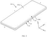
- FIG. 3 is a three-dimensional diagram of another electronic device 100 including the flexible display panel 1 shown in FIG. 2 .
- an unfilled corner is formed at an edge corner of the flexible display panel 1
- the light-transmitting cover plate 2 keeps the complete four-curved shape
- the edge corners of the flexible display panel 1 stay out of the edge corners of the light-transmitting cover plate 2.
- a black light shielding layer may be disposed on the inner surface of the edge corner of the light-transmitting cover plate 2 to shield an internal structure of the electronic device 100, thereby ensuring appearance consistency of the electronic device 100.
- a black edge at the edge corner of the light-transmitting cover plate 2 is wider than black edges of two sides, the top, and the bottom of the light-transmitting cover plate 2.
- a round corner at the edge of the light-transmitting cover plate does not match a round corner of a display region, affecting appearance of the electronic device 100.
- FIG. 4 is a main view of the electronic device 100 shown in FIG. 1a .
- FIG. 5 is a local enlarged view of region I of the electronic device 100 shown in FIG. 4 .
- FIG. 6 is a main view of the electronic device 100 shown in FIG. 3 .
- FIG. 7 is a local enlarged view of region II of the electronic device 100 shown in FIG. 6 . It can be seen from FIG. 4 to FIG.
- FIG. 8 is a three-dimensional diagram of a flexible display panel 1 according to some embodiments of this application.
- FIG. 9 is a cross-sectional view along line A-A of the flexible display panel 1 shown in FIG. 8 .
- line A-A is a plane on which line A-A and arrows of two ends of the line A-A are located.
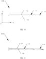
- FIG. 10 is a cross-sectional view along line B-B of the flexible display panel 1 shown in FIG. 8 .
- FIG. 11 is a cross-sectional view along line C-C of the flexible display panel 1 shown in FIG.
- the flexible display panel 1 shown in this embodiment differs from the flexible display panel 1 shown in FIG. 1 in that in this embodiment, the flexible display panel 1 further includes a third side view portion 14, in addition to the main view portion 11, the first side view portion 12, and the second side view portion 13.
- the main view portion 11 is a main portion for a user to view the flexible display panel 1. Based on this, the main view portion 11 is located at the middle of the flexible display panel 1. Compared with the first side view portion 12, the second side view portion 13, and the third side view portion 14, the main view portion 11 has a larger area for the user to obtain images and information that are displayed on the flexible display panel 1.
- the main view portion 11 is in a planar sheet shape, and the main view portion 11 is roughly rectangular in shape.
- the main view portion 11 may alternatively be square, triangular, prismatic, polygonal, or of other shapes.
- an example in which the main view portion 11 is roughly rectangular in shape is used for description, which should not be considered as a special limitation on this application.
- the main view portion 11 includes a display face 11a and a back face 11b.
- the display face 11a is a surface for the main view portion 11 to display images and information.
- the back face 11b is back to the display face 11a.
- the first side view portion 12, the second side view portion 13, and the third side view portion 14 are secondary portions for the user to view the flexible display panel 1.
- the first side view portion 12, the second side view portion 13, and the third side view portion 14 are disposed at an edge of the main view portion 11.
- the main view portion 11 is provided with a middle portion and an edge, where the edge of the main view portion 11 includes a first section 112, a second section 113, and a corner section 111.
- the first section 112 extends in the Y-axis direction
- the second section 113 extends in the X-axis direction
- the first section 112 and the second section 113 are two straight sections perpendicular to each other, meaning that an included angle between an extending line of the first section 112 and an extending line of the second section 113 is approximately equal to 90°.
- the included angle between the extending line of the first section 112 and the extending line of the second section 113 may alternatively be less than 90° or greater than 90°.
- an example in which the included angle between the extending line of the first section 112 and the extending line of the second section 113 is approximately equal to 90° is used for description, which should not be considered as a special limitation on this application.
- a length of the first section 112 may be greater than a length of the second section 113.
- the first section 112 is a long side of the main view portion 11, and the second section 113 is a short side of the main view portion 11.
- the length of the first section 112 may alternatively be less than or equal to the length of the second section 113.
- an example in which the length of the first section 112 is greater than the length of the second section 113 is used for description, which should not be considered as a special limitation on this application.
- the corner section 111 is connected between the first section 112 and the second section 113.
- the corner section 111 may be a transition arc connected between the first section 112 and the second section 113.
- the edge of the main view portion 11 has a smooth transition; and the first side view portion 12, the third side view portion 14, and the second side view portion 13 that are disposed at the edge of the main view portion 11 can transit smoothly in sequence, preventing damage to the flexible display panel 1 caused by an excessively large bent angle between the first side view portion 12 and the third side view portion 14, between the third side view portion 14 and the second side view portion 13, and inside the third side view portion 14.
- the first side view portion 12, the second side view portion 13, and the third side view portion 14 are all bent relative to the main view portion 11 and are entirely in a curved surface shape with smooth transition. Specifically, as shown in FIG. 8 to FIG. 11 , the first side view portion 12 extends from the first section 112 of the edge of the main view portion 11 in a direction leaving the middle portion of the main view portion 11 and bends toward a back face side of the main view portion 11.
- the back face side of the main view portion 11 is a side of the back face 11b of the main view portion 11 further away from the display face 11a.
- the first side view portion 12 bends toward the back face side, to be specific, normal directions of all parts of the first side view portion 12 gradually tilt toward the back face side of the main view portion 11 from an end closer to the main view portion 11 to an end further away from the main view portion 11.
- the second side view portion 13 extends from the second section 113 of the edge of the main view portion 11 in a direction leaving the middle portion of the main view portion 11 and bends toward the back face side of the main view portion 11.
- the third side view portion 14 is connected between the first side view portion 12 and the second side view portion 13, and the third side view portion 14 extends from the corner section 111 of the edge of the main view portion 11 in a direction leaving the middle portion of the main view portion 11 and bends toward the back face side of the main view portion 11.
- the flexible display panel 1 is not only provided with a curved shape on the side, the top, or the bottom, but also provided with a curved shape at an edge corner.
- the flexible display panel 1 is not only disposed in the curved shape on the side, the top, or the bottom of a light-transmitting cover plate 2, but also disposed in a curved shape at an edge corner of the light-transmitting cover plate 2.
- a black edge width of a corner of a front face of the electronic device 100 is consistent with a black edge width of the side, the top, or the bottom, ensuring that the front face of the electronic device 100 looks good.
- the screen-to-body ratio of the electronic device 100 can be further increased, improving information carrying efficiency of the display region and enhancing product competitiveness.
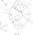
- FIG. 12 is a local enlarged view of region III of the flexible display panel 1 shown in FIG. 8 .
- FIG. 13 is a schematic structural diagram of the flexible display panel 1 shown in FIG. 12 when viewed from direction D.
- An edge of the first side view portion 12 further away from the main view portion 11 is an outer contour of the first side view portion 12, denoted as E2 in FIG. 12 and FIG. 13 .
- An edge of the second side view portion 13 further away from the main view portion 11 is an outer contour of the second side view portion 13, denoted as E3 in FIG. 12 and FIG. 13 .
- one end of the outer contour E1 of the third side view portion 14 connects to the outer contour E2 of the first side view portion 12, with an intersection of a1.
- the other end of the outer contour E1 of the third side view portion 14 connects to the outer contour E3 of the second side view portion 13, with an intersection of a2.
- the part of the outer contour E1 that upwarps toward the main view portion 11 has an apex a3.
- the middle portion of the outer contour E1 of the third side view portion 14 upwarps toward the main view portion 11 in a direction perpendicular to the main view portion 11 (that is, the Z-axis direction).
- At least a perpendicular distance from the apex a3 of the outer contour E1 to the display face 11a of the main view portion 11 is greater than a perpendicular distance from the intersection a1 to the display face 11a of the main view portion 11; and the perpendicular distance from the apex a3 to the display face 11a of the main view portion 11 is also greater than a perpendicular distance from the intersection a2 to the display face 11a of the main view portion 11.
- a part located between an upwarp part in the middle portion of the outer contour E1 of the third side view portion 14 and the corner section 111 forms a redundant part of the edge corner of the flexible display panel 1.
- the redundant part is in an unfolded state without generating any wrinkle.
- the flexible display panel 1 in the embodiments of this application implements smooth transition between the outer contour E1 and the outer contour E2, between the outer contour E1 and the outer contour E3, and between all parts in the outer contour E1. Therefore, when such flexible display panel 1 is applied to the electronic device 100, regions of the front face of the electronic device 100 at the corners have no notch or depression with unnatural transition, better meeting use habits of users.
- FIG. 14 is a schematic diagram of orthographic projections of the first side view portion 12, the second side view portion 13, and the third side view portion 14 of the flexible display panel 1 shown in FIG. 13 on the display face 11a of the main view portion 11.
- the orthographic projection of the outer contour E2 of the first side view portion 12 on the display face 11a of the main view portion 11 is a first projection E21.
- the orthographic projection of the outer contour E3 of the second side view portion 13 on the display face 11a of the main view portion 11 is a second projection E31.
- the orthographic projection of the outer contour E1 of the third side view portion 14 on the display face 11a of the main view portion 11 is a third projection E11.
- the third projection E11 is a transition arc connected between the first projection E21 and the second projection E31, and the center of the transition arc is O.
- the orthographic projection of the third side view portion 14 on the display face 11a of the main view portion 11 is a fourth projection E.
- An intersection K of an extending line of the first section 112 and an extending line of the second section 113 is located within the fourth projection E.
- the third side view portion 14 has a larger area, and therefore has a larger orthographic projection on the display face 11a, which can increase the screen-to-body ratio of the electronic device 100.
- FIG. 15 is a cross-sectional view at section L of the flexible display panel 1 shown in FIG. 14 .
- the section L is a plane that passes through the apex a3 of the outer contour E1 and the center O of the third projection E11 and that is perpendicular to the main view portion 11.
- a height of the third side view portion 14 in a direction perpendicular to the main view portion 11 is h, where h is greater than 0 millimeters (mm). Specifically, h is greater than or equal to 0.05 mm and less than or equal to 0.25 mm. In this way, the flexible display panel 1 has a moderate redundancy on the third side view portion 14, preventing the flexible display panel 1 from generating wrinkles as far as possible while maintaining the curved shape of the flexible display panel 1.
- FIG. 16 is a schematic structural diagram of the flexible display 1 shown in FIG.8 .
- two first side view portions 12 and two second side view portions 13 are provided.
- the two first side view portions 12 are respectively disposed on two opposite sides of the main view portion 11.
- the two second side view portions 13 are respectively disposed on another two opposite sides of the main view portion 11.
- Four third side view portions 14 are provided.
- the four third side view portions 14 are respectively disposed on four corner sections of the edge of the main view portion 11, with each being connected between the corresponding adjacent first side view portion 12 and second side view portion 13.
- the flexible display panel 1 is in a four-curved shape and can match a four-curved light-transmitting cover plate to form a four-curved screen, so that an electronic device with such four-curved screen can be formed, thereby improving a screen-to-body ratio and product competitiveness of the electronic device.
- the flexible display panel 1 is also provided with a camera hole 15.
- the camera hole 15 is opposite a camera of the electronic device, so that external ambient light can pass through the camera hole 15 to enter the camera, implementing picture or video shooting.
- the flexible display panel 1 is also provided with a circuit connecting terminal 16 at an outer edge of the second side view portion 13.
- the circuit connecting terminal 16 is configured to be electrically connected to a flexible printed circuit board (flexible printed circuit, FPC) 17, to transmit images and information to the flexible display panel 1 through the FPC 17.
- FPC flexible printed circuit
- the circuit connecting terminal 16 may alternatively be disposed at an outer edge of the first side view portion 12 or an outer edge of the third side view portion 14.
- the display is a display including the flexible display panel 1 provided in any one of the foregoing embodiments.
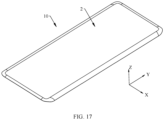
- FIG. 17 is a schematic structural diagram of a display 10 according to some embodiments of this application.
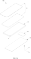
- FIG. 18 is an exploded view of the display 10 shown in FIG. 17 .
- the display 10 further includes a light-transmitting cover plate 2.
- a material of the light-transmitting cover plate 2 includes but is not limited to glass and plastic.
- the light-transmitting cover plate 2 has an outer surface m1 and an inner surface m2 that is back to the outer surface m1.
- FIG. 19 and FIG. 20 is a schematic structural diagram of the outer surface m1 of the light-transmitting cover plate 2 of the display 10 shown in FIG. 17 and FIG. 18 .
- FIG. 19 is a schematic structural diagram of the outer surface m1 of the light-transmitting cover plate 2 of the display 10 shown in FIG. 17 and FIG. 18 .
- FIG. 19 is a schematic structural diagram of the outer surface m1 of the light-transmitting cover plate 2 of the display 10 shown in FIG. 17 and FIG. 18 .
- FIG. 20 is a schematic structural diagram of the inner surface m2 of the light-transmitting cover plate 2 of the display 10 shown in FIG. 17 and FIG. 18 .
- the outer surface m1 of the light-transmitting cover plate 2 faces toward the outside of the electronic device
- the inner surface m2 of the light-transmitting cover plate 2 faces toward the inside of the electronic device.
- the flexible display panel 1 is disposed on an inner side of the light-transmitting cover plate 2 through stacking.
- the light-transmitting cover plate 2 is configured to protect the flexible display panel 1.
- the light-transmitting cover plate 2 includes a flat plate portion 21, and a first arc sheet portion 22, a second arc sheet portion 23, and a third arc sheet portion 24 that are disposed at an edge of the flat plate portion 21.
- the flat plate portion 21 is roughly rectangular in shape. In some other embodiments, the flat plate portion 21 may alternatively be square, triangular, prismatic, polygonal, or of other shapes. In this embodiment of this application, an example in which the flat plate portion 21 is roughly rectangular in shape is used for description, which should not be considered as a special limitation on this application.
- the flat plate portion 21 includes a middle portion and an edge, where the edge of the flat plate portion 21 includes a first edge 212, a second edge 213, and a corner edge 211.
- the first arc sheet portion 22, the second arc sheet portion 23, and the third arc sheet portion 24 each bend relative to the flat plate portion 21 and are entirely in an arc sheet shape with smooth transition.
- the first arc sheet portion 22 extends from the first edge 212 of the flat plate portion 21 in a direction leaving the middle portion of the flat plate portion 21 and bends toward an inner side of the flat plate portion 21.
- the second arc sheet portion 23 extends from the second edge 213 of the flat plate portion 21 in a direction leaving the middle portion of the flat plate portion 21 and bends toward the inner side of the flat plate portion 21.
- the third arc sheet portion 24 is connected between the first arc sheet portion 22 and the second arc sheet portion 23, and the third arc sheet portion 24 extends from the corner edge 211 of the flat plate portion 21 in a direction leaving the middle portion of the flat plate portion 21 and bends toward the inner side of the flat plate portion 21.
- the light-transmitting cover plate 2 is not only provided with an arc shape on the side, the top, or the bottom of an inner surface 22, but also provided with an arc shape at an edge corner to fit the flexible display panel 1.
- the main view portion 11 of the flexible display panel 1 and the flat plate portion 21 of the light-transmitting cover plate 2 are stacked, the display face 11a of the main view portion 11 faces toward the flat plate portion 21, and the flat plate portion 21 fits the main view portion 11.
- the first side view portion 12 of the flexible display panel 1 and the first arc sheet portion 22 of the light-transmitting cover plate 2 are stacked, and the first arc sheet portion 22 fits the first side view portion 12.
- the second side view portion 13 of the flexible display panel 1 and the second arc sheet portion 23 of the light-transmitting cover plate 2 are stacked, and the second arc sheet portion 23 fits the second side view portion 13.
- the third side view portion 14 of the flexible display panel 1 and the third arc sheet portion 24 of the light-transmitting cover plate 2 are stacked, and the third arc sheet portion 24 fits the third side view portion 14. In this way, the light-transmitting cover plate 2 fits the flexible display panel 1.
- the flexible display panel 1 can be attached to the inner surface 22 of the light-transmitting cover plate 2 to form curved shapes on two sides, the top, or the bottom of the flexible display panel 1.
- FIG. 21 is a schematic structural diagram of the light-transmitting cover plate 2 shown in FIG. 19 when viewed from direction F.
- An edge of the first arc sheet portion 22 further away from the flat plate portion 21 is an outer contour of the first arc sheet portion 22, denoted as e2 in FIG. 21 .
- An edge of the second arc sheet portion 23 further away from the flat plate portion 21 is an outer contour of the second arc sheet portion 23, denoted as e3 in FIG. 21 .
- An edge of the third arc sheet portion 24 further away from the flat plate portion 21 is an outer contour of the third arc sheet portion 24, denoted as e1 in FIG. 21 .
- Two ends of the outer contour e1 of the third arc sheet portion 24 respectively connect to the outer contour e2 of the first arc sheet portion 22 and the outer contour e3 of the second arc sheet portion 23.
- a middle portion of the outer contour e1 of the third arc sheet portion 24 upwarps toward the flat plate portion 21 in a direction perpendicular to the flat plate portion 21.
- one end of the outer contour e1 of the third arc sheet portion 24 connects to the outer contour e2 of the first arc sheet portion 22, with an intersection of A1.
- the other end of the outer contour e1 of the third arc sheet portion 24 connects to the outer contour e3 of the second arc sheet portion 23, with an intersection of A2.
- the part of the outer contour e1 that upwarps toward the flat plate portion 21 has an apex A3.
- the middle portion of the outer contour e1 of the third arc sheet portion 24 upwarps toward the flat plate portion 21 in the direction perpendicular to the flat plate portion 21.
- At least a perpendicular distance from the apex A3 of the outer contour e1 to an outer surface of the flat plate portion 21 is greater than a perpendicular distance from the intersection A1 to the outer surface of the flat plate portion 21; and the perpendicular distance from the apex A3 to the outer surface of the flat plate portion 21 is also greater than a perpendicular distance from the intersection A2 to the outer surface of the flat plate portion 21.
- the third arc sheet portion 24 fits the third side view portion 14, ensuring that they can be fitted together.
- the outer contour e1 may alternatively have no upwarp part.
- the third arc sheet portion 24 does not fit the third side view portion 14, and distances from all parts in the third arc sheet portion 24 to the third side view portion 14 are unequal.
- a gap between the third arc sheet portion 24 and the third side view portion 14 may be filled through a liquid light-transmitting adhesive (such as an OCA adhesive) with an unfixed shape.
- the liquid light-transmitting adhesive has fluidity and can flow from a region with a small gap to a region with a large gap to keep respective shapes of the third arc sheet portion 24 and the third side view portion 14.
- smooth transition is present between the outer contour e1 and the outer contour e2, between the outer contour e1 and the outer contour e3, and between all parts in the outer contour e1. In this way, smooth transition at an edge of the light-transmitting cover plate 2 prevents generation of unnatural notches or depressions, better meeting use habits of users.
- an orthographic projection of the outer contour e2 on the outer surface of the flat plate portion 21 is a fifth projection; an orthographic projection of the outer contour e3 on the outer surface of the flat plate portion 21 is a sixth projection; and an orthographic projection of the outer contour e1 on the outer surface of the flat plate portion 21 is a seventh projection.
- the seventh projection is a transition arc connected between the fifth projection and the sixth projection.
- an orthographic projection of the third arc sheet portion 24 on the outer surface of the flat plate portion 21 is an eighth projection, and an intersection of an extending line of the first edge 212 and an extending line of the second edge 213 is located within the eight projection.
- the third arc sheet portion 24 has a relatively large area and can cover the third side view portion 14 to effectively protect the third side view portion 14.
- two first arc sheet portions 22 and two second arc sheet portions 23 are provided.
- the two first arc sheet portions 22 are respectively disposed on two opposite sides of the flat plate portion 21.
- the two second arc sheet portions 23 are respectively disposed on another two opposite sides of the flat plate portion 21.
- Two first side view portions 12 of the flexible display panel 1 are respectively stacked with the two first arc sheet portions 22, and the two first arc sheet portions 22 respectively fit the two first side view portions 12 of the flexible display panel 1.
- Two second side view portions 13 of the flexible display panel 1 are respectively stacked with the two second arc sheet portions 23, and the two arc sheet portions 23 respectively fit the two second side view portions 13 of the flexible display panel 1.
- Four third arc sheet portions 24 are provided.
- the four third arc sheet portions 24 are respectively disposed at four corner edges of the edge of the flat plate portion 21, with each being connected between the corresponding adjacent first arc sheet portion 22 and second arc sheet portion 23.
- Four third side view portions 14 of the flexible display panel 1 are respectively stacked with the four third arc sheet portions 24, and the four third arc sheet portions 24 respectively fit the four third side view portions 14 of the flexible display panel 1.
- the light-transmitting cover plate 2 can cover the two first side view portions 12, the two second side view portions 13, and the four third side view portions 14 of the flexible display 1 to effectively protect the flexible display 1.
- FIG. 22 is a cross-sectional view along line D-D of the light-transmitting cover plate 2 shown in FIG. 19 .
- the first arc sheet portion 22 has a decreasing thickness from one end connecting to the flat plate portion 21 to the outer contour of the first arc sheet portion 22. It should be noted that a thickness of each part of an arc sheet portion (such as the first arc sheet portion 22) described in this embodiment and the following embodiments is a distance from an inner surface of that part of the arc sheet portion to an outer surface along a normal direction of the inner surface.
- an outer surface of the first arc sheet portion 22 has a larger radian, allowing a user to enjoy pictures with a more-3D effect.
- the inner surface of the first arc sheet portion 22 is a surface of the first arc sheet portion 22 facing toward the inside of an electronic device when the light-transmitting cover plate 2 is applied to the electronic device.
- the outer surface of the first arc sheet portion 22 is a surface of the first arc sheet portion 22 facing toward the outside of an electronic device when the light-transmitting cover plate 2 is applied to the electronic device.
- a processing procedure of the first arc sheet portion 22 described in the foregoing embodiments may be as follows: First, an edge portion of a planar light-transmitting cover plate is bent through hot pressing to form an equally thick arc sheet portion; and then part of a material of an outer surface of the equally thick arc sheet portion is removed through a computerised numerical control machine (computerised numerical control machine, CNC) to form the first arc sheet portion 22 with a decreasing thickness.
- CNC computerised numerical control machine
- a length L1 of the first arc sheet portion 22 in a direction parallel to the flat plate portion 21 and perpendicular to the first edge 212 of the flat plate portion 21 is less than or equal to 6 mm.
- L1 may be 2 mm, 2.5 mm, 3 mm, 3.5 mm, 4 mm, 4.5 mm, 5 mm, 5.5 mm, 6 mm, or the like.
- the first arc sheet portion 22 occupies a small area on a front face of the electronic device. With a given display region, an area of the flat plate portion 21 can be set larger, so that a user can view more images or information displayed on the flexible display panel 1 from the flat plate portion 21, thereby reducing visual errors.
- a height H1 of the first arc sheet portion 22 in a direction perpendicular to the flat plate portion 21 is less than or equal to 3.5 mm.
- H1 may be 1 mm, 1.5 mm, 2 mm, 2.5 mm, 3 mm, 3.5 mm, or the like.
- the height H1 of the first arc sheet portion 22 affects height of the light-transmitting cover plate 2
- the height of the light-transmitting cover plate 2 affects thickness of the electronic device. Therefore, when the height H1 of the first arc sheet portion 22 is less than or equal to 3.5 mm, such a small height H1 allows the electronic device to be thinner.
- an edge of the inner surface of the first arc sheet portion 22 further away from the inner surface of the flat plate portion 21 is an outer edge of the inner surface of the first arc sheet portion 22.
- An included angle ⁇ 1 between a tangent plane at the outer edge of the inner surface of the first arc sheet portion 22 and the outer surface of the flat plate portion 21 is less than or equal to 89°.
- the included angle ⁇ 1 may be 50°, 55°, 60°, 65°, 70°, 75°, 80°, 85°, 89°, or the like. In this way, a user can enjoy pictures with a more-3D effect.
- a curvature radius R1 of the inner surface of the first arc sheet portion 22 is greater than or equal to 2.5 mm.
- the curvature radius R1 may be 2.5 mm, 3 mm, 3.5 mm, 4 mm, or the like. In this way, the curvature radius R1 of the inner surface of the first arc sheet portion 22 is large, so that a bent angle is small in the case of bending a planar light-transmitting cover plate through hot pressing to form the first arc sheet portion 22, guaranteeing forming yield of the first arc sheet portion 22.
- Curvature radii R1 of all parts of the inner surface of the first arc sheet portion 22 may be the same or different, which is not specifically limited in this embodiment of this application.
- FIG. 23 is a cross-sectional view along line E-E of the light-transmitting cover plate 2 shown in FIG. 19 .
- the second arc sheet portion 23 has a decreasing thickness from one end connecting to the flat plate portion 21 to the outer contour of the second arc sheet portion 23. In this way, on a basis that an inner surface of the second arc sheet portion 23 fits the second side view portion 13 of the flexible display panel 1, an outer surface of the second arc sheet portion 23 has a larger radian, allowing a user to view a more-3D picture.
- the inner surface of the second arc sheet portion 23 is a surface of the second arc sheet portion 23 facing toward the inside of an electronic device when the light-transmitting cover plate 2 is applied to the electronic device.
- the outer surface of the second arc sheet portion 23 is a surface of the second arc sheet portion 23 facing toward the outside of an electronic device when the light-transmitting cover plate 2 is applied to the electronic device.
- the second arc sheet portion 23 may alternatively be formed through a combination of hot pressing and CNC, so as to reduce forming difficulty and processing cost of the second arc sheet portion 23.
- a length L2 of the second arc sheet portion 23 in a direction parallel to the flat plate portion 21 and perpendicular to the second edge 213 of the flat plate portion 21 is less than or equal to 6 mm.
- L2 may be 1 mm, 1.5 mm, 2 mm, 2.5 mm, 3 mm, 3.5 mm, 4 mm, or the like.
- the second arc sheet portion 23 occupies a small area on a front face of the electronic device. With a given display region, an area of the flat plate portion can be set larger, so that a user can view more information or images displayed on the flexible display panel 1 from the flat plate portion, thereby reducing visual errors.
- a height H2 of the second arc sheet portion 23 in the direction perpendicular to the flat plate portion 21 is less than or equal to 1.5 mm.
- H2 may be 0.5 mm, 0.8 mm, 1 mm, 1.1 mm, 1.2 mm, 1.3 mm, 1.4 mm, 1.5 mm, or the like.
- the height H2 of the second arc sheet portion 23 is less than or equal to 1.5 mm, under a given thickness of the electronic device, such a small height H2 allows the middle frame to be designed thicker, facilitating arrangement of structures such as a USB interface, a speaker sound output hole, and an earphone jack on the top edge and the bottom edge of the frame.
- an edge of the inner surface of the second arc sheet portion 23 further away from the inner surface of the flat plate portion 21 is an outer edge of the inner surface of the second arc sheet portion 23.
- An included angle ⁇ 2 between a tangent plane at the outer edge of the inner surface of the second arc sheet portion 23 and the outer surface of the flat plate portion 21 is less than or equal to 89°.
- the included angle ⁇ 2 may be 10°, 20°, 25°, 30°, 35°, 40°, 45°, 50°, or the like. In this way, a user can enjoy pictures with a more-3D effect.
- a curvature radius R2 of the inner surface of the second arc sheet portion 23 is greater than or equal to 2.5 mm.
- the curvature radius R2 may be 2.5 mm, 3 mm, 3.5 mm, 4 mm, or the like. In this way, the curvature radius R2 of the inner surface of the second arc sheet portion 23 is large, so that a bent angle is small in the case of bending a planar light-transmitting cover plate by hot pressing or other methods to form the second arc sheet portion 23, guaranteeing forming yield of the second arc sheet portion 23.
- Curvature radii R2 of all parts of the inner surface of the second arc sheet portion 23 may be the same or different, which is not specifically limited in this embodiment of this application.
- FIG. 24 is a cross-sectional view along line G-G of the light-transmitting cover plate 2 shown in FIG. 19 .
- the third arc sheet portion 24 has a decreasing thickness from one end connecting to the flat plate portion 21 to the outer contour of the third arc sheet portion 24. In this way, on a basis that an inner surface of the third arc sheet portion 24 fits the third side view portion 14 of the flexible display panel 1, an outer surface of the third arc sheet portion 24 has a larger radian, allowing a user to enjoy pictures with a more-3D effect.
- the third arc sheet portion 24 may alternatively be formed through a combination of hot pressing and CNC, so as to reduce forming difficulty and processing cost of the third arc sheet portion 24.
- a height H3 of the third arc sheet portion 24 in the direction perpendicular to the flat plate portion 21 is greater than or equal to 1 mm and less than or equal to 2 mm. In this way, the height H3 of the third arc sheet portion is moderate, avoiding a large upwarp on the middle portion of the outer edge of the third arc sheet portion from affecting a 3D display effect of an electronic device.
- the display 10 further includes a polarizer 3.
- the polarizer 3 is disposed on the display face of the flexible display panel 1.
- the polarizer 3 is made into the same shape as the surface of the flexible display panel 1 and fits the flexible display panel 1 without gaps or wrinkles, so as to form a display panel with the polarizer.
- the display 10 further includes a light-transmitting adhesive layer 4.
- the light-transmitting adhesive layer 4 is disposed between the polarizer 3 and the light-transmitting cover plate 2.
- the light-transmitting adhesive layer 4 includes but is not limited to clear adhesives such as an optionally clear adhesive (optically clear adhesive, OCA) and is configured to bond the display panel with the polarizer to the inner surface 22 of the light-transmitting cover plate 2.
- OCA optical clear adhesive
- the light-transmitting adhesive layer 4 has fluidity, so when the display panel with the polarizer is being bonded to the inner surface 22 of the light-transmitting cover plate 2, bonding pressure can be adjusted to enable the light-transmitting adhesive layer 4 to flow from a position with a small gap to a position with a large gap, so that the flexible display panel 1 can be formed as a four-curved shape without wrinkles.
- the electronic device is a type of electronic device with a display function.
- the electronic device includes but is not limited to a mobile phone, a tablet personal computer (tablet personal computer), a laptop computer (laptop computer), a personal digital assistant (personal digital assistant, PDA), a personal computer, a notebook computer, a vehicle-mounted device, and a wearable device (such as a watch).
- FIG. 25 is a schematic diagram of an electronic device 100 according to some embodiments of this application.
- the electronic device 100 is a mobile phone.
- the electronic 100 includes a display 10, a middle frame 20, a back cover (not shown in the figure) and a circuit board (not shown in the figure).
- the display 10 is the display 10 described in the foregoing embodiments.
- the display 10, the middle frame 20, and the back cover are connected in sequence.
- An inner accommodating space of the electronic device 100 is formed between the middle frame 20 and the back cover, and the circuit board is disposed in the inner accommodating space.
- the circuit board is a main board of the mobile phone.
- the circuit board may alternatively be a secondary board of the mobile phone.
- the circuit board is electrically connected to the flexible display panel of the display 10 to transmit images or information to the flexible display panel.
- the electronic device provided in this embodiment of this application includes the display 10 described in the foregoing embodiment, the electronic device can implement four-curved display with a high screen-to-body ratio, making the product more competitive.
Landscapes
- Engineering & Computer Science (AREA)
- Theoretical Computer Science (AREA)
- Physics & Mathematics (AREA)
- Computer Hardware Design (AREA)
- General Physics & Mathematics (AREA)
- Human Computer Interaction (AREA)
- General Engineering & Computer Science (AREA)
- Microelectronics & Electronic Packaging (AREA)
- Optics & Photonics (AREA)
- Devices For Indicating Variable Information By Combining Individual Elements (AREA)
Claims (15)
- Eine flexible Anzeigetafel (1), bestehend aus einem Hauptansichtsbereich (11) und einem ersten Seitenansichtsbereich (12), einem zweiten Seitenansichtsbereich (13) und einem dritten Seitenansichtsbereich (14), die an einem Rand des Hauptansichtsbereichs (11) angeordnet sind; wobeider Hauptansichtsbereich (11) umfasst einen mittleren Bereich und eine Kante, wobei die Kante des Hauptansichtsbereichs einen ersten Abschnitt (112), einen zweiten Abschnitt (113) und einen Eckabschnitt (111) umfasst, der zwischen dem ersten Abschnitt (112) und dem zweiten Abschnitt (113) verbunden ist; und der Hauptansichtsbereich (11) umfasst eine Anzeigefläche (11a) und eine Rückseite (11b), die der Anzeigefläche (11a) gegenüberliegt; undder erste Seitenansichtsabschnitt (12) erstreckt sich vom ersten Abschnitt (112) in eine Richtung, die den mittleren Teil des Hauptansichtsabschnitts (11) verlässt und sich zur Rückseite hin biegt; der zweite Seitenansichtsabschnitt (13) erstreckt sich vom zweiten Abschnitt (113) in eine Richtung, die den mittleren Teil des Hauptansichtsabschnitts (11) verlässt und sich zur Rückseite hin biegt; und der dritte Seitenansichtsabschnitt (14) ist zwischen dem ersten Seitenansichtsabschnitt (11) und dem zweiten Seitenansichtsabschnitt (13) verbunden, und der dritte Seitenansichtsabschnitt (14) erstreckt sich vom Eckabschnitt (111) in eine Richtung, die den mittleren Teil des Hauptansichtsabschnitts (11) verlässt und sich zur Rückseite hin biegt,wobei zwei Enden einer Außenkontur (E1) des dritten Seitenansichtsabschnitts (14) jeweils mit einer Außenkontur (E2) des ersten Seitenansichtsabschnitts (12) und einer Außenkontur (E3) des zweiten Seitenansichtsabschnitts (13) verbunden sind, und ein mittlerer Abschnitt der Außenkontur des dritten Seitenansichtsabschnitts (14) sich in einer Richtung senkrecht zum Hauptansichtsabschnitt (11) zum Hauptansichtsabschnitt (11) hin aufwölbt, wobei ein Ende der Außenkontur (E1) des dritten Seitenansichtsabschnitts (14) an einem ersten Schnittpunkt (a1) mit der Außenkontur (E2) des ersten Seitenansichtsabschnitts (12) verbunden ist, und das andere Ende der Außenkontur (E1) des dritten Seitenansichtsabschnitts (14) an einem zweiten Schnittpunkt (a2) mit der Außenkontur (E3) des zweiten Seitenansichtsabschnitts (13) verbunden ist,dadurch gekennzeichnet, dass der mittlere Teil der Außenkontur (E1) des dritten Seitenansichtsabschnitts (14), der sich zum Hauptansichtsabschnitt (11) hin aufwölbt, einen Scheitelpunkt (a3) umfasst, wobei mindestens ein senkrechter Abstand vom Scheitelpunkt (a3) zur Anzeigefläche (11a) des Hauptansichtsabschnitts (11) größer ist als ein senkrechter Abstand vom ersten Schnittpunkt (a1) zur Anzeigefläche (11a) des Hauptansichtsabschnitts (11), und der senkrechte Abstand vom Scheitelpunkt (a3) zur Anzeigefläche (11a) des Hauptansichtsabschnitts (11) ebenfalls größer ist als ein senkrechter Abstand vom zweiten Schnittpunkt (a2) zur Anzeigefläche (11a) des Hauptansichtsabschnitts (11).
- Das flexible Anzeigefeld nach Anspruch 1, wobei eine orthografische Projektion der Außenkontur des ersten Seitenansichtsabschnitts auf der Anzeigefläche eine erste Projektion (E21) ist; eine orthografische Projektion der Außenkontur des zweiten Seitenansichtsabschnitts auf der Anzeigefläche eine zweite Projektion (E31) ist; und eine orthografische Projektion der Außenkontur des dritten Seitenansichtsabschnitts auf der Anzeigefläche eine dritte Projektion (E11) ist, wobei die dritte Projektion (E11) ein Übergangsbogen ist, der zwischen der ersten Projektion (E21) und der zweiten Projektion (E31) verbunden ist.
- Das flexible Anzeigefeld nach Anspruch 1 oder 2, wobei eine orthografische Projektion des dritten Seitenansichtsabschnitts auf die Anzeigefläche eine vierte Projektion (E) ist, und ein Schnittpunkt (K) einer Verlängerungslinie des ersten Abschnitts und einer Verlängerungslinie des zweiten Abschnitts innerhalb der vierten Projektion (E) liegt.
- Das flexible Anzeigefeld nach einem der Ansprüche 1 bis 3, wobei eine Höhe des dritten Seitenansichtsabschnitts in der Richtung senkrecht zum Hauptansichtsabschnitt größer oder gleich 0,05 mm und kleiner oder gleich 0,25 mm ist.
- Das flexible Anzeigepanel nach einem der Ansprüche 1 bis 4, wobei sowohl der erste Abschnitt als auch der zweite Abschnitt gerade Abschnitte sind und der erste Abschnitt senkrecht zum zweiten Abschnitt steht.
- Das flexible Anzeigefeld nach einem der Ansprüche 1 bis 5, wobei der Eckabschnitt ein Übergangsbogen ist, der zwischen dem ersten Abschnitt und dem zweiten Abschnitt verbunden ist.
- Das flexible Anzeigefeld gemäß einem der Ansprüche 1 bis 6, wobei eine Länge des ersten Abschnitts größer ist als eine Länge des zweiten Abschnitts.
- Eine Anzeige (10), umfassend eine lichtdurchlässige Abdeckplatte (2) und das flexible Anzeigepanel (1) gemäß einem der Ansprüche 1 bis 7, wobeiDie lichtdurchlässige Abdeckplatte (2) umfasst einen flachen Plattenteil (21) sowie einen ersten Bogenblechteil (22), einen zweiten Bogenblechteil (23) und einen dritten Bogenblechteil (24), die an einem Rand des flachen Plattenteils (21) angeordnet sind, wobei der flache Plattenteil (21) einen Mittelteil und einen Rand umfasst, und der Rand des flachen Plattenteils (21) einen ersten Rand (212), einen zweiten Rand (213) und einen Eckrand (211) umfasst, der zwischen dem ersten Rand (212) und dem zweiten Rand (213) verbunden ist;der erste Bogenblechteil (22) erstreckt sich von der ersten Kante (212) in eine Richtung, die den mittleren Teil des Flachblechteils (21) verlässt, und biegt sich zur Innenseite des Flachblechteils (21); der zweite Bogenblechteil (23) erstreckt sich von der zweiten Kante (213) in eine Richtung, die den mittleren Teil des Flachblechteils (21) verlässt, und biegt sich zur Innenseite des Flachblechteils (21); und der dritte Bogenblechteil (24) ist zwischen dem ersten Bogenblechteil (22) und dem zweiten Bogenblechteil (23) verbunden, und der dritte Bogenblechteil (24) erstreckt sich von der Eckkante (211) in eine Richtung, die den mittleren Teil des Flachblechteils (21) verlässt, und biegt sich zur Innenseite des Flachblechteils (21); undDas flexible Anzeigefeld (1) ist auf der Innenseite der lichtdurchlässigen Abdeckplatte (2) angeordnet; der Hauptansichtsbereich (11) des flexiblen Anzeigefelds (1) und der Flachplattenbereich (21) sind gestapelt, und die Anzeigefläche (11a) des Hauptansichtsbereichs (11) ist zum Flachplattenbereich (21) hin ausgerichtet; der erste Seitenansichtsbereich (12) des flexiblen Anzeigefelds (1) und der erste Bogenblechbereich (22) sind gestapelt; der zweite Seitenansichtsbereich (13) des flexiblen Anzeigefelds (1) und der zweite Bogenblechbereich (23) sind gestapelt; und der dritte Seitenansichtsbereich (14) des flexiblen Anzeigefelds (1) und der dritte Bogenblechbereich (24) sind gestapelt.
- Die Anzeige gemäß Anspruch 8, wobei zwei Enden einer Außenkontur (e1) des dritten Bogenblechteils jeweils mit einer Außenkontur (e2) des ersten Bogenblechteils und einer Außenkontur (e3) des zweiten Bogenblechteils verbunden sind, und ein mittlerer Teil der Außenkontur (e1) des dritten Bogenblechteils sich in einer Richtung senkrecht zur Flachplattenportion zur Flachplattenportion hin aufwölbt.
- Die Anzeige nach Anspruch 8 oder 9, wobei der erste Bogenabschnitt, der zweite Bogenabschnitt und der dritte Bogenabschnitt jeweils eine abnehmende Dicke von einem Ende, das mit dem Flachplattenabschnitt verbunden ist, bis zur Außenkontur aufweisen.
- Die Anzeige gemäß einem der Ansprüche 8 bis 10, wobei eine Länge des ersten Bogenblechteils in einer Richtung parallel zum Flachblechteil und senkrecht zur ersten Kante und eine Länge des zweiten Bogenblechteils in einer Richtung parallel zum Flachblechteil und senkrecht zur zweiten Kante beide kleiner oder gleich 6 mm sind.
- Die Anzeige nach einem der Ansprüche 8 bis 11, wobei eine Höhe des ersten Bogenblattabschnitts in der Richtung senkrecht zur Flachplattenportion kleiner oder gleich 3,5 mm ist.
- Die Anzeige nach einem der Ansprüche 8 bis 12, wobei eine Höhe des zweiten Bogenblattabschnitts in der Richtung senkrecht zum Flachplattenabschnitt kleiner oder gleich 1,5 mm ist.
- Die Anzeige gemäß einem der Ansprüche 8 bis 13, wobei ein eingeschlossener Winkel (θ1) zwischen einer Tangentialebene an einem Außenrand einer inneren Oberfläche des ersten Bogenblechteils und einer äußeren Oberfläche des Flachplattenabschnitts und ein eingeschlossener Winkel (θ2) zwischen einer Tangentialebene an einem Außenrand einer inneren Oberfläche des zweiten Bogenblechteils und der äußeren Oberfläche des Flachplattenabschnitts beide kleiner oder gleich 89° sind.
- Ein elektronisches Gerät (100), umfassend das Display (10) gemäß einem der Ansprüche 8 bis 14, einen Mittelrahmen (20), eine Rückabdeckung und eine Leiterplatte, wobei
Das Display (10), der Mittelrahmen (20) und die Leiterplatte sind nacheinander verbunden, ein innerer Aufnahmeraum des elektronischen Geräts (100) wird zwischen dem Mittelrahmen (20) und der Rückabdeckung gebildet, die Leiterplatte ist im inneren Aufnahmeraum angeordnet und die Leiterplatte ist elektrisch mit dem flexiblen Anzeigefeld (1) des Displays (10) verbunden.
Applications Claiming Priority (3)
| Application Number | Priority Date | Filing Date | Title |
|---|---|---|---|
| CN202111436962 | 2021-11-29 | ||
| CN202210113128.3A CN115019641B (zh) | 2021-11-29 | 2022-01-29 | 一种柔性显示面板、显示屏和电子设备 |
| PCT/CN2022/116905 WO2023093195A1 (zh) | 2021-11-29 | 2022-09-02 | 一种柔性显示面板、显示屏和电子设备 |
Publications (3)
| Publication Number | Publication Date |
|---|---|
| EP4210033A1 EP4210033A1 (de) | 2023-07-12 |
| EP4210033A4 EP4210033A4 (de) | 2024-01-03 |
| EP4210033B1 true EP4210033B1 (de) | 2025-02-26 |
Family
ID=83067144
Family Applications (1)
| Application Number | Title | Priority Date | Filing Date |
|---|---|---|---|
| EP22838620.7A Active EP4210033B1 (de) | 2021-11-29 | 2022-09-02 | Flexible anzeigetafel, anzeigebildschirm und elektronische vorrichtung |
Country Status (4)
| Country | Link |
|---|---|
| US (1) | US12373005B2 (de) |
| EP (1) | EP4210033B1 (de) |
| CN (2) | CN115019641B (de) |
| WO (1) | WO2023093195A1 (de) |
Families Citing this family (2)
| Publication number | Priority date | Publication date | Assignee | Title |
|---|---|---|---|---|
| CN117794158B (zh) * | 2022-09-28 | 2026-01-02 | 荣耀终端股份有限公司 | 一种散热器和电子设备 |
| CN117789603A (zh) * | 2024-01-08 | 2024-03-29 | 武汉华星光电半导体显示技术有限公司 | 显示模组和显示装置 |
Family Cites Families (31)
| Publication number | Priority date | Publication date | Assignee | Title |
|---|---|---|---|---|
| CN100356498C (zh) * | 2003-01-17 | 2007-12-19 | 松下电器产业株式会社 | 等离子体显示面板 |
| US9137918B2 (en) * | 2012-09-28 | 2015-09-15 | Htc Corporation | Electronic apparatus and method for assembling the same |
| KR20150007872A (ko) * | 2013-07-12 | 2015-01-21 | 삼성디스플레이 주식회사 | 곡면 형상을 갖는 표시 장치 |
| KR102091030B1 (ko) * | 2013-10-18 | 2020-03-19 | 삼성디스플레이 주식회사 | 표시장치 |
| EP3537694B1 (de) * | 2015-02-06 | 2023-08-02 | Samsung Electronics Co., Ltd. | Elektronische vorrichtung mit anzeige mit gebogenem bereich |
| KR102367971B1 (ko) * | 2017-06-16 | 2022-02-25 | 삼성디스플레이 주식회사 | 커버 윈도우 및 커버 윈도우를 포함하는 표시 장치 |
| KR102385727B1 (ko) * | 2017-09-14 | 2022-04-13 | 삼성디스플레이 주식회사 | 표시 장치 |
| US10444795B2 (en) * | 2018-03-16 | 2019-10-15 | Wuhan China Star Optoelectronics Semiconductor Display Technology Co., Ltd. | Glass cover plate for a display assembly, display assembly, and terminal |
| CN208471912U (zh) * | 2018-04-12 | 2019-02-05 | 深圳市东丽华科技有限公司 | 一种玻璃盖板 |
| US11054861B2 (en) * | 2018-06-11 | 2021-07-06 | Apple Inc. | Electronic devices having displays with expanded edges |
| CN110661906A (zh) * | 2018-06-28 | 2020-01-07 | 华为技术有限公司 | 一种曲面盖板、曲面盖板的加工方法和终端 |
| US11175769B2 (en) * | 2018-08-16 | 2021-11-16 | Apple Inc. | Electronic device with glass enclosure |
| CN111048699A (zh) * | 2018-10-15 | 2020-04-21 | Oppo(重庆)智能科技有限公司 | 一种oled显示面板的制作方法、显示屏模组和电子设备 |
| KR102713989B1 (ko) * | 2018-11-19 | 2024-10-07 | 삼성디스플레이 주식회사 | 표시 장치 및 그 제조 방법 |
| CN111385390A (zh) * | 2018-12-29 | 2020-07-07 | 中兴通讯股份有限公司 | 曲面屏结构及其制造方法以及终端设备 |
| KR102628165B1 (ko) * | 2019-04-23 | 2024-01-23 | 삼성디스플레이 주식회사 | 표시 장치 |
| CN111899640B (zh) * | 2019-05-06 | 2021-10-26 | 华为技术有限公司 | 具有曲面显示屏的电子设备 |
| KR102797660B1 (ko) * | 2019-06-21 | 2025-04-18 | 삼성디스플레이 주식회사 | 표시 장치 및 그 제조 방법 |
| CN112311967B (zh) * | 2019-07-26 | 2022-04-01 | Oppo广东移动通信有限公司 | 电子设备 |
| CN112311914A (zh) * | 2019-07-30 | 2021-02-02 | Oppo广东移动通信有限公司 | 曲面盖板、显示屏及电子设备 |
| CN112445275A (zh) * | 2019-08-30 | 2021-03-05 | Oppo广东移动通信有限公司 | 电子设备、显示屏组件、显示屏盖板以及贴合方法 |
| CN112565485A (zh) * | 2019-09-26 | 2021-03-26 | Oppo广东移动通信有限公司 | 显示模组及其制作方法、电子设备 |
| CN112732013A (zh) * | 2019-10-29 | 2021-04-30 | Oppo广东移动通信有限公司 | 电子设备、显示屏组件及其显示屏盖板 |
| CN112909040B (zh) | 2019-11-19 | 2023-07-04 | Oppo广东移动通信有限公司 | 显示模组及其制作方法、显示屏组件、电子设备 |
| CN110992831B (zh) * | 2019-12-13 | 2021-06-29 | 华为技术有限公司 | 柔性显示面板及电子设备 |
| CN210927685U (zh) * | 2020-02-24 | 2020-07-03 | Oppo广东移动通信有限公司 | 电子设备、显示屏组件及其显示屏盖板 |
| CN113497840B (zh) * | 2020-04-03 | 2022-10-04 | Oppo广东移动通信有限公司 | 电子设备、显示屏组件及显示屏盖板 |
| CN111710245B (zh) | 2020-07-17 | 2022-05-20 | 京东方科技集团股份有限公司 | 柔性显示面板及其制备方法、显示装置、显示模组 |
| KR102830849B1 (ko) * | 2020-11-26 | 2025-07-04 | 엘지디스플레이 주식회사 | 표시장치 |
| WO2022178664A1 (zh) * | 2021-02-23 | 2022-09-01 | 京东方科技集团股份有限公司 | 显示模组及其制造方法、显示装置 |
| CN113053236B (zh) * | 2021-03-02 | 2022-11-29 | Oppo广东移动通信有限公司 | 电子设备、显示模组及盖板 |
-
2022
- 2022-01-29 CN CN202210113128.3A patent/CN115019641B/zh active Active
- 2022-01-29 CN CN202310261037.9A patent/CN116580637B/zh active Active
- 2022-09-02 WO PCT/CN2022/116905 patent/WO2023093195A1/zh not_active Ceased
- 2022-09-02 US US18/017,183 patent/US12373005B2/en active Active
- 2022-09-02 EP EP22838620.7A patent/EP4210033B1/de active Active
Also Published As
| Publication number | Publication date |
|---|---|
| CN116580637A (zh) | 2023-08-11 |
| EP4210033A1 (de) | 2023-07-12 |
| US12373005B2 (en) | 2025-07-29 |
| US20240231435A1 (en) | 2024-07-11 |
| CN115019641B (zh) | 2023-03-24 |
| EP4210033A4 (de) | 2024-01-03 |
| WO2023093195A1 (zh) | 2023-06-01 |
| CN116580637B (zh) | 2026-02-13 |
| CN115019641A (zh) | 2022-09-06 |
Similar Documents
| Publication | Publication Date | Title |
|---|---|---|
| EP4210033B1 (de) | Flexible anzeigetafel, anzeigebildschirm und elektronische vorrichtung | |
| EP4271151B1 (de) | Elektronische vorrichtung mit wasserdichter struktur | |
| CN110225159A (zh) | 显示装置、电子设备及显示装置制备方法 | |
| CN218455965U (zh) | 显示模组及电子设备 | |
| KR20210130474A (ko) | 글라스를 포함하는 투명 커버 및 이와 결합된 폴더블 디스플레이를 포함하는 전자 장치 | |
| WO2023077950A1 (zh) | 可折叠终端 | |
| KR20240008224A (ko) | 플렉서블 디스플레이를 포함하는 전자 장치 | |
| CN114694493A (zh) | 折叠显示终端 | |
| CN115346434B (zh) | 一种透光盖板、柔性显示面板、显示屏和电子设备 | |
| US20230263004A1 (en) | Electronic Devices Having Curved Displays With Supporting Frames | |
| KR20220099047A (ko) | 글라스의 손상을 줄일 수 있는 전자 장치 | |
| KR102950779B1 (ko) | 커버 윈도우 및 표시 장치 | |
| US12556626B2 (en) | Foldable electronic apparatus | |
| KR102809418B1 (ko) | 폴더블 디스플레이 장치 | |
| CN216391092U (zh) | 盖板和显示装置 | |
| CN214043707U (zh) | 显示装置及电子设备 | |
| CN116052544A (zh) | 显示模组、支撑膜和显示装置 | |
| HK40077093A (en) | Flexible display panel, display screen and electronic device | |
| CN118414651A (zh) | 显示模组及显示装置 | |
| HK40077093B (en) | Flexible display panel, display screen and electronic device | |
| CN113851046A (zh) | 一种电子设备 | |
| CN112927622A (zh) | 可折叠显示屏和显示装置 | |
| EP4535339A1 (de) | Elektronische vorrichtung mit flexibler anzeige | |
| CN222786007U (zh) | 电子设备 | |
| US20250072259A1 (en) | Display device |
Legal Events
| Date | Code | Title | Description |
|---|---|---|---|
| STAA | Information on the status of an ep patent application or granted ep patent |
Free format text: STATUS: UNKNOWN |
|
| STAA | Information on the status of an ep patent application or granted ep patent |
Free format text: STATUS: THE INTERNATIONAL PUBLICATION HAS BEEN MADE |
|
| PUAI | Public reference made under article 153(3) epc to a published international application that has entered the european phase |
Free format text: ORIGINAL CODE: 0009012 |
|
| STAA | Information on the status of an ep patent application or granted ep patent |
Free format text: STATUS: REQUEST FOR EXAMINATION WAS MADE |
|
| 17P | Request for examination filed |
Effective date: 20230116 |
|
| AK | Designated contracting states |
Kind code of ref document: A1 Designated state(s): AL AT BE BG CH CY CZ DE DK EE ES FI FR GB GR HR HU IE IS IT LI LT LU LV MC MK MT NL NO PL PT RO RS SE SI SK SM TR |
|
| REG | Reference to a national code |
Ref country code: DE Ref legal event code: R079 Free format text: PREVIOUS MAIN CLASS: G09F0009300000 Ipc: G06F0001160000 Ref country code: DE Ref legal event code: R079 Ref document number: 602022011245 Country of ref document: DE Free format text: PREVIOUS MAIN CLASS: G09F0009300000 Ipc: G06F0001160000 |
|
| A4 | Supplementary search report drawn up and despatched |
Effective date: 20231204 |
|
| RIC1 | Information provided on ipc code assigned before grant |
Ipc: G06F 1/16 20060101AFI20231128BHEP |
|
| STAA | Information on the status of an ep patent application or granted ep patent |
Free format text: STATUS: EXAMINATION IS IN PROGRESS |
|
| 17Q | First examination report despatched |
Effective date: 20240619 |
|
| 17Q | First examination report despatched |
Effective date: 20240626 |
|
| GRAP | Despatch of communication of intention to grant a patent |
Free format text: ORIGINAL CODE: EPIDOSNIGR1 |
|
| STAA | Information on the status of an ep patent application or granted ep patent |
Free format text: STATUS: GRANT OF PATENT IS INTENDED |
|
| DAV | Request for validation of the european patent (deleted) | ||
| DAX | Request for extension of the european patent (deleted) | ||
| INTG | Intention to grant announced |
Effective date: 20241001 |
|
| GRAS | Grant fee paid |
Free format text: ORIGINAL CODE: EPIDOSNIGR3 |
|
| GRAA | (expected) grant |
Free format text: ORIGINAL CODE: 0009210 |
|
| STAA | Information on the status of an ep patent application or granted ep patent |
Free format text: STATUS: THE PATENT HAS BEEN GRANTED |
|
| AK | Designated contracting states |
Kind code of ref document: B1 Designated state(s): AL AT BE BG CH CY CZ DE DK EE ES FI FR GB GR HR HU IE IS IT LI LT LU LV MC MK MT NL NO PL PT RO RS SE SI SK SM TR |
|
| REG | Reference to a national code |
Ref country code: GB Ref legal event code: FG4D |
|
| REG | Reference to a national code |
Ref country code: CH Ref legal event code: EP |
|
| REG | Reference to a national code |
Ref country code: DE Ref legal event code: R096 Ref document number: 602022011245 Country of ref document: DE |
|
| REG | Reference to a national code |
Ref country code: IE Ref legal event code: FG4D |
|
| REG | Reference to a national code |
Ref country code: NL Ref legal event code: FP |
|
| PG25 | Lapsed in a contracting state [announced via postgrant information from national office to epo] |
Ref country code: RS Free format text: LAPSE BECAUSE OF FAILURE TO SUBMIT A TRANSLATION OF THE DESCRIPTION OR TO PAY THE FEE WITHIN THE PRESCRIBED TIME-LIMIT Effective date: 20250526 |
|
| PG25 | Lapsed in a contracting state [announced via postgrant information from national office to epo] |
Ref country code: FI Free format text: LAPSE BECAUSE OF FAILURE TO SUBMIT A TRANSLATION OF THE DESCRIPTION OR TO PAY THE FEE WITHIN THE PRESCRIBED TIME-LIMIT Effective date: 20250226 |
|
| PG25 | Lapsed in a contracting state [announced via postgrant information from national office to epo] |
Ref country code: PL Free format text: LAPSE BECAUSE OF FAILURE TO SUBMIT A TRANSLATION OF THE DESCRIPTION OR TO PAY THE FEE WITHIN THE PRESCRIBED TIME-LIMIT Effective date: 20250226 |
|
| PG25 | Lapsed in a contracting state [announced via postgrant information from national office to epo] |
Ref country code: ES Free format text: LAPSE BECAUSE OF FAILURE TO SUBMIT A TRANSLATION OF THE DESCRIPTION OR TO PAY THE FEE WITHIN THE PRESCRIBED TIME-LIMIT Effective date: 20250226 |
|
| REG | Reference to a national code |
Ref country code: LT Ref legal event code: MG9D |
|
| PG25 | Lapsed in a contracting state [announced via postgrant information from national office to epo] |
Ref country code: IS Free format text: LAPSE BECAUSE OF FAILURE TO SUBMIT A TRANSLATION OF THE DESCRIPTION OR TO PAY THE FEE WITHIN THE PRESCRIBED TIME-LIMIT Effective date: 20250626 Ref country code: NO Free format text: LAPSE BECAUSE OF FAILURE TO SUBMIT A TRANSLATION OF THE DESCRIPTION OR TO PAY THE FEE WITHIN THE PRESCRIBED TIME-LIMIT Effective date: 20250526 |
|
| PG25 | Lapsed in a contracting state [announced via postgrant information from national office to epo] |
Ref country code: HR Free format text: LAPSE BECAUSE OF FAILURE TO SUBMIT A TRANSLATION OF THE DESCRIPTION OR TO PAY THE FEE WITHIN THE PRESCRIBED TIME-LIMIT Effective date: 20250226 |
|
| PG25 | Lapsed in a contracting state [announced via postgrant information from national office to epo] |
Ref country code: LV Free format text: LAPSE BECAUSE OF FAILURE TO SUBMIT A TRANSLATION OF THE DESCRIPTION OR TO PAY THE FEE WITHIN THE PRESCRIBED TIME-LIMIT Effective date: 20250226 Ref country code: PT Free format text: LAPSE BECAUSE OF FAILURE TO SUBMIT A TRANSLATION OF THE DESCRIPTION OR TO PAY THE FEE WITHIN THE PRESCRIBED TIME-LIMIT Effective date: 20250626 |
|
| PG25 | Lapsed in a contracting state [announced via postgrant information from national office to epo] |
Ref country code: GR Free format text: LAPSE BECAUSE OF FAILURE TO SUBMIT A TRANSLATION OF THE DESCRIPTION OR TO PAY THE FEE WITHIN THE PRESCRIBED TIME-LIMIT Effective date: 20250527 Ref country code: BG Free format text: LAPSE BECAUSE OF FAILURE TO SUBMIT A TRANSLATION OF THE DESCRIPTION OR TO PAY THE FEE WITHIN THE PRESCRIBED TIME-LIMIT Effective date: 20250226 |
|
| REG | Reference to a national code |
Ref country code: AT Ref legal event code: MK05 Ref document number: 1771253 Country of ref document: AT Kind code of ref document: T Effective date: 20250226 |
|
| PG25 | Lapsed in a contracting state [announced via postgrant information from national office to epo] |
Ref country code: SE Free format text: LAPSE BECAUSE OF FAILURE TO SUBMIT A TRANSLATION OF THE DESCRIPTION OR TO PAY THE FEE WITHIN THE PRESCRIBED TIME-LIMIT Effective date: 20250226 |
|
| PGFP | Annual fee paid to national office [announced via postgrant information from national office to epo] |
Ref country code: NL Payment date: 20250814 Year of fee payment: 4 |
|
| PG25 | Lapsed in a contracting state [announced via postgrant information from national office to epo] |
Ref country code: SM Free format text: LAPSE BECAUSE OF FAILURE TO SUBMIT A TRANSLATION OF THE DESCRIPTION OR TO PAY THE FEE WITHIN THE PRESCRIBED TIME-LIMIT Effective date: 20250226 |
|
| PG25 | Lapsed in a contracting state [announced via postgrant information from national office to epo] |
Ref country code: DK Free format text: LAPSE BECAUSE OF FAILURE TO SUBMIT A TRANSLATION OF THE DESCRIPTION OR TO PAY THE FEE WITHIN THE PRESCRIBED TIME-LIMIT Effective date: 20250226 |
|
| PGFP | Annual fee paid to national office [announced via postgrant information from national office to epo] |
Ref country code: DE Payment date: 20250730 Year of fee payment: 4 |
|
| PG25 | Lapsed in a contracting state [announced via postgrant information from national office to epo] |
Ref country code: IT Free format text: LAPSE BECAUSE OF FAILURE TO SUBMIT A TRANSLATION OF THE DESCRIPTION OR TO PAY THE FEE WITHIN THE PRESCRIBED TIME-LIMIT Effective date: 20250226 |
|
| PG25 | Lapsed in a contracting state [announced via postgrant information from national office to epo] |
Ref country code: AT Free format text: LAPSE BECAUSE OF FAILURE TO SUBMIT A TRANSLATION OF THE DESCRIPTION OR TO PAY THE FEE WITHIN THE PRESCRIBED TIME-LIMIT Effective date: 20250226 |
|
| PG25 | Lapsed in a contracting state [announced via postgrant information from national office to epo] |
Ref country code: CZ Free format text: LAPSE BECAUSE OF FAILURE TO SUBMIT A TRANSLATION OF THE DESCRIPTION OR TO PAY THE FEE WITHIN THE PRESCRIBED TIME-LIMIT Effective date: 20250226 Ref country code: EE Free format text: LAPSE BECAUSE OF FAILURE TO SUBMIT A TRANSLATION OF THE DESCRIPTION OR TO PAY THE FEE WITHIN THE PRESCRIBED TIME-LIMIT Effective date: 20250226 |
|
| PG25 | Lapsed in a contracting state [announced via postgrant information from national office to epo] |
Ref country code: RO Free format text: LAPSE BECAUSE OF FAILURE TO SUBMIT A TRANSLATION OF THE DESCRIPTION OR TO PAY THE FEE WITHIN THE PRESCRIBED TIME-LIMIT Effective date: 20250226 |
|
| PG25 | Lapsed in a contracting state [announced via postgrant information from national office to epo] |
Ref country code: SK Free format text: LAPSE BECAUSE OF FAILURE TO SUBMIT A TRANSLATION OF THE DESCRIPTION OR TO PAY THE FEE WITHIN THE PRESCRIBED TIME-LIMIT Effective date: 20250226 |
|
| REG | Reference to a national code |
Ref country code: DE Ref legal event code: R097 Ref document number: 602022011245 Country of ref document: DE |
|
| PLBE | No opposition filed within time limit |
Free format text: ORIGINAL CODE: 0009261 |
|
| STAA | Information on the status of an ep patent application or granted ep patent |
Free format text: STATUS: NO OPPOSITION FILED WITHIN TIME LIMIT |
|
| 26N | No opposition filed |
Effective date: 20251127 |