EP4209654B1 - Steckverbinder - Google Patents
Steckverbinder Download PDFInfo
- Publication number
- EP4209654B1 EP4209654B1 EP23150180.0A EP23150180A EP4209654B1 EP 4209654 B1 EP4209654 B1 EP 4209654B1 EP 23150180 A EP23150180 A EP 23150180A EP 4209654 B1 EP4209654 B1 EP 4209654B1
- Authority
- EP
- European Patent Office
- Prior art keywords
- plug
- connector
- bridge
- locking
- tray
- Prior art date
- Legal status (The legal status is an assumption and is not a legal conclusion. Google has not performed a legal analysis and makes no representation as to the accuracy of the status listed.)
- Active
Links
Images


Classifications
-
- E—FIXED CONSTRUCTIONS
- E06—DOORS, WINDOWS, SHUTTERS, OR ROLLER BLINDS IN GENERAL; LADDERS
- E06B—FIXED OR MOVABLE CLOSURES FOR OPENINGS IN BUILDINGS, VEHICLES, FENCES OR LIKE ENCLOSURES IN GENERAL, e.g. DOORS, WINDOWS, BLINDS, GATES
- E06B3/00—Window sashes, door leaves, or like elements for closing wall or like openings; Layout of fixed or moving closures, e.g. windows in wall or like openings; Features of rigidly-mounted outer frames relating to the mounting of wing frames
- E06B3/66—Units comprising two or more parallel glass or like panes permanently secured together
- E06B3/663—Elements for spacing panes
- E06B3/667—Connectors therefor
Definitions
- the invention relates to a multi-part connector with the features in the preamble of the main claim.
- Such a multi-part connector is from the DE 10 2008 048 998 B4 known.
- the bridge is loosely inserted into the plug-in shell and is locked with the bridge web edges on the shell base between the base studs and the adjacent shell web with a clamping closure.
- the connection of the plugged-together connector parts is insecure.
- the DE 20 2004 004 734 U1 , EP 2 027 355 B1 and EP 2 134 916 B1 show other forms of multi-part connectors in which the bridges plugged into the plug-in shell stand up on the shell base with the lower edge of their side bridge webs and are locked to the shell webs by means of side studs on the bridge webs.
- the protruding studs engage in recesses below the cut-out retaining elements of the shell webs. There is no separate guide device for the connector parts.
- the DE 20 2017 101 315 U1 and EP 1 785 575 A2 show one-piece connectors without a bridge.
- the claimed connector technology i.e. the connector, its connector parts, the plug connection and the connection method have various advantages.
- the claimed connector has an additional guide device for its connector parts.
- the guide device is provided separately. It is spatially and functionally separate from the locking device.
- the guide device can be provided and designed to guide the connector parts when plugging them together in a plugging direction and also in the plugged-together position.
- the plugging direction can be aligned transversely to the shell base, in particular transversely to its main plane. It can preferably be aligned perpendicularly to the shell base, in particular perpendicular to its main plane.
- the guide device can hold the plugged-together connector parts together in the direction of the longitudinal axis. The holding function can be effective in the plugged-together final position and also beforehand when plugging the connector parts together.
- the locking device and the additional separate guide device have the advantage that the plugged-together connector parts, ie the plug-in shell and the bridge, have a better and more precise connection with each other and can withstand higher loads.
- the guide device also improves the handling and assignment or mutual positioning of the connector parts when they are plugged together. The correct plug position and the locking device can be found more quickly and reliably. These advantages also apply to the stressed plug connection.
- the high load capacity is particularly advantageous when inserting the multi-part connector into a hollow profile and the forces that act in this process. This applies both when the connector is pre-inserted onto a hollow profile and when hollow profiles or hollow profile ends are inserted onto the connector from both sides.
- the connector parts remain in their mutual position and are not displaced against each other or even separated from each other by the insertion forces.
- the inserted bridge is at least in the area of the connector center and at the joint.
- the leakage of granulated drying agent from a hollow profile at the joint into the interior of the insulating glazing can be prevented with a high degree of certainty.
- the gas tightness is also improved.
- the locking device and the separate guide device each have locking elements and guide elements that interact with each other.
- the locking elements and the guide elements are arranged at a distance from each other and are functionally separated. It is advantageous for the locking elements and the guide elements to interact in a form-fitting manner.
- the said guide elements and the said locking elements can be arranged at a mutual distance transverse to the longitudinal axis and possibly transverse to the shell base of the connector. Accordingly, the locking devices and the guide devices are spaced apart from one another, which ensures a particularly favorable overall connection of the plugged-together connector parts.
- the guide device which is preferably located at the front in the direction of insertion, can act first when the connector parts are plugged together and can have a guiding function for the subsequent exact meeting and closing of the interacting locking elements and the locking function.
- the guide device can be easily found and closed when the connector parts are plugged together. It also has a positioning function for the connector parts.
- the interacting guide elements each have a stop edge and an associated stop side, which work together for guiding purposes and are each aligned transversely to the shell base.
- the stop edges and stop sides of the interacting guide elements can be aligned parallel to each other and preferably along the plug-in direction. They can also be aligned at an angle to the plug-in direction. be.
- the respective interacting guide elements are at a greater distance from the shell base of the connector than the respective interacting locking elements. It is also advantageous to arrange the respective interacting guide elements and the respective interacting locking elements in the region of an axial connector center of the connector.
- the inserted bridge is located at least in the area of the connector center. From here, it can extend along the longitudinal axis in both directions.
- the bridge can be significantly shorter than the plug-in shell and can act primarily at the joint and in the adjacent area on both sides of the hollow profiles.
- the connector can be divided into two connector legs that extend from the connector center along the longitudinal axis in different directions.
- the multi-part connector is preferably designed as a straight connector. Alternatively, it can have an angled shape and be designed as a corner connector.
- the guide device in particular the interacting guide elements, can be designed to hold the plugged-together connector parts against each other in the direction of the longitudinal axis. This can be done with a stop function, in particular a preferably two-sided stop function.
- the guide device and the guide elements can allow a limited relative mobility of the connector parts in the direction of the longitudinal axis.
- the guide device and the guide elements position the plugged-together connector parts with a stop function that acts on both sides in the direction of the longitudinal axis.
- the bridge and the plug-in shell can thus have a predetermined and exact mutual position that can be assumed without play or at least with little play. This is beneficial for absorbing forces and resistance when plugging the plug-in connector into a hollow profile and for the aforementioned guide function.
- the guide device and the locking device as well as their interacting guide elements and locking elements can be designed and arranged differently with respect to the connector parts.
- One or more of the interacting guide elements of the bridge and the plug-in shell can be arranged at the connector center and/or at least one of the axially adjacent connector areas or connector legs on both sides.
- An arrangement at the connector center has the advantage of stabilizing and supporting the connector and its connector parts at the connector center and is also beneficial for a centering guide function when plugging the connector parts together.
- the guide element(s) in a plug-in shell can be arranged on a free edge of one or both shell webs.
- the locking elements can be arranged on the shell web at a distance below the free edge.
- the one or more guide elements of the plug-in shell can each be designed as a recess on the free edge of the shell web(s) and have an access opening pointing away from the shell base.
- the guide element(s) on the bridge can be inserted here when the connector parts are plugged together.
- the recess can, for example, have a U-shape or V-shape or another suitable shape in the side view.
- the guide device can comprise a central guide element at the connector center with one-sided or two-sided arrangement on the connector. This is advantageous for central relative positioning and also support of the connector parts.
- a central guide element can be arranged as a recess between spring-loaded stop lugs of a one-sided or two-sided center finding.
- the guide device can have one or more decentralized guide elements, in particular recesses. These can be arranged between the center finding and an adjacent retaining element on a free edge of the shell web(s). One or more recesses can also be arranged at a greater distance from the connector center between adjacent retaining elements on a free edge of the shell web.
- one or more guide elements of the bridge are each designed as a laterally protruding side projection and protrude into one of the said recesses.
- One or more guide elements of the bridge can also be supported on a lower edge of a recess and rest there to fulfil the aforementioned support function of the guide device. This is particularly advantageous if the locking device only has a stop function that acts against the mutual lifting of the connector parts transversely to the said longitudinal axis.
- other structural and functional designs of guide elements of the bridge are possible.
- a locking element of the plug-in shell can be designed, for example, as a latching opening on a shell web.
- Another locking element of the plug-in shell can be designed and function, for example, as a stop on a shell web.
- the locking opening enables a positive and locking interaction with a locking element on the bridge.
- This can also have a guiding and supporting function.
- the locking opening can be arranged at a distance below the guiding element(s) or recesses on the free edge of the shell web and at a distance above the shell base. The inserted bridge can thus be distanced from the shell base and supported on the locking opening.
- a locking element of the bridge can be designed as a lateral locking projection that protrudes transversely from the bridge and engages positively in the associated locking opening on a shell web.
- the locking projection There are various options for the design of the locking projection.
- a particularly favorable design is a locking lug that is angled diagonally and in the direction of the roof. This locking lug shape can allow the locking lug to slide along the When the connector parts are put together, the shell bridge causes the bridge to deform and the locking lug then snaps into the locking opening.
- the locking lug can rest with its underside on a lower edge of the locking opening. Its upper side can rest on an upper edge of the locking opening or be close to it. This can prevent the bridge from lifting off in the opposite direction to the plugging direction.
- the locking opening and the associated lateral locking projection can vary in shape and be coordinated with one another.
- the locking opening can, for example, have a circular, oval or prismatic cross-sectional shape with rounded corners if necessary.
- the lateral locking projection can, for example, be designed as a locking pin protruding from the side of the bridge.
- the locking pin can, for example, have a cylindrical or cuboid shape with side walls aligned parallel to one another and to the shell base.
- the underside can be aligned at an angle for the aforementioned sliding.
- a wedge-shaped outer contour of a side bridge web that widens towards the bridge roof is also advantageous.
- the outer contour can be adapted to a shell web that is directed diagonally outwards, so that the bridge web with the wedge-shaped outer contour and the shell web can lie flat against each other. This is beneficial for the stability of the connector and the plug connection.
- a locking element of the plug-in shell can be designed as a stop on a shell web that projects laterally into the shell cavity.
- the stop can be formed in particular by a correspondingly projecting web section of a shell web that is angled several times and divided into several web sections.
- the claimed design and arrangement of the web sections is advantageous for absorbing side or width tolerances and height tolerances.
- the shell web in question can spring in a controlled manner to absorb the tolerance and without disadvantageous or undesirable deformations.
- a locking element of the bridge can be designed as a laterally projecting stop hump and preferably arranged on the lower edge of one or both bridge webs.
- the preferably wedge-shaped stop hump can also spring back when the connector parts are put together and then engage behind the said stop on the shell web in a form-fitting manner.
- the stop hump can also have a support foot on the underside, which enables the bridge to be supported on the shell base. Alternatively or additionally, the aforementioned support function of the guide device can be used.
- the bridge can have a recessed and preferably rounded roof recess on the bridge roof in the longitudinal direction. It can also have a roof slope that slopes down to the edge of the roof in this area. This is advantageous in order to accommodate and align any deformations on the hollow profile wall adjacent to the bridge roof, in particular a profile roof, when attaching a hollow profile. Such deformations can occur, for example, when separating a hollow profile from a profile strand.
- the alignment function of Roof recess and/or roof slope can bring the relevant profile roof area into the desired position and ensure a tight connection of the profile front sides at the joint.
- the bridge can have a flat bridge roof on the outside.
- one or more roof projections possibly arranged axially, can be arranged on the bridge roof in the longitudinal direction and on one or both edge sides. These can engage in hollow roof webs of a hollow profile. They can prevent an undesired flow of granulated drying agent and can also have a guiding function.
- a sealing agent e.g. a sealing strip aligned transversely to the longitudinal axis of the connector, can also be arranged on the bridge roof. The sealing agent can be located at the joint of the hollow profile(s) in the plug connection.
- the bridge roof itself can be arranged close to the profile roof without contact or can rest against the profile roof with little pressure.
- the plug-in shell can have various and plural retaining elements, which are arranged, for example, on the free edge of the shell web(s) and/or on the shell base.
- retaining elements arranged on the free edge of the shell web(s)
- a rectangular shape in side view is advantageous, in particular for optimal retention in a plugged-on hollow profile, in particular a warm-edge hollow profile.
- the rectangular retaining elements can have parallel upper and lower edges and an upright front edge. The parallel upper and lower edges can extend parallel to the main plane of the shell base.
- the connector parts of the claimed connector can be made of the same or different materials. It is advantageous for the connector if the The bridge is designed as a plastic part and the plug-in shell is designed as a metal part, in particular as a stamped and bent part.
- the metallic web shell offers high mechanical stability in conjunction with a favorable spring effect.
- the design of the bridge as a plastic part has the advantage of a simple and inexpensive design in terms of construction and manufacturing technology with options for adaptation to the plug-in shell.
- the plug-in shell can be designed as a standard connector that can also be used for other purposes, in particular as an individual connector for hollow profiles.
- the connector parts can be coordinated with one another.
- the connector parts each represent an independent, separately claimable invention.
- the connector parts can be manufactured and supplied individually or as an ensemble.
- the connector parts can be put together by the manufacturer of the connector parts or elsewhere, e.g. by an insulating glass manufacturer.
- the hollow profile is preferably designed as a warm-edge hollow profile. It can have a profile body made of plastic and a profile shell made of metal, in particular stainless steel. However, the hollow profile can also have any other design than a pure plastic profile or a pure metal profile, e.g. a drawn or rolled metal profile.
- the plug connector and the plug connection can have the following advantageous designs. These can be used individually or in any combination with each other and with the claimed designs.
- interacting guide elements and interacting locking elements can be arranged at a mutual distance that is directed transversely to the longitudinal axis.
- the interacting guide elements can be arranged in front of the interacting locking elements in the plugging direction.
- the respective cooperating guide elements and the respective cooperating locking elements can be arranged in the region of an axial connector center of the connector.
- the cooperating guide elements can be designed to guide and direct the connector parts along the plugging direction when they are plugged together. In particular, they can prevent mutual slipping in the longitudinal direction of the connector.
- the cooperating guide elements can be designed to hold and preferably position the plugged-together connector parts in the direction of the longitudinal axis with a preferably two-sided stop function. This holding function and, if applicable, positioning function can be effective when plugging together and in the plugged-in position.
- the guide device in particular the interacting guide elements, can be designed to support the assembled connector parts against each other against compressive forces in a direction transverse to the longitudinal axis.
- the interacting guide elements can each have a stop edge and a stop side, which interact for guiding purposes and are each aligned transversely to the shell base.
- the stop edges and stop sides of the interacting guide elements can be aligned parallel to each other and preferably along the plugging direction.
- the cooperating locking elements can be designed to prevent the plugged-together connector parts from lifting off and loosening in the opposite direction to the plugging direction.
- the cooperating locking elements can be designed to position and/or support the plugged-together connector parts along and across the longitudinal axis.
- the cooperating locking elements can be designed to support the bridge in the plugging direction with contact or at a distance from the shell base.
- One or more guide elements and one or more locking elements of the plug-in shell can each be arranged on one or both shell webs.
- One or more guide elements and one or more locking elements of the bridge can each be arranged on one or both long sides of the bridge, in particular on the outside of one or both bridge webs.
- the guide element(s) of the bridge may be arranged close to the bridge roof and the locking element(s) of the bridge may be arranged at a distance below the bridge roof.
- Interacting guide elements of the bridge and the plug-in shell can be arranged at the axial connector center and/or at the axially adjacent connector areas on both sides.
- the guide element(s) of the plug-in shell can be arranged on a free edge of the shell web.
- the locking element(s) of the plug-in shell can be arranged on the shell web at a distance below the free edge of the shell web.
- One or more guide elements of the plug-in shell can each be designed as a recess on the free edge of the shell web with an access opening pointing away from the shell base.
- One or more recesses on the plug-in shell can have an upright web edge that forms a stop edge and that interacts with a stop side of the associated guide element of the bridge for a stop function.
- One or more recesses can be arranged between a center finding and an adjacent retaining element on a free edge of the shell web.
- One or more recesses can be arranged between adjacent retaining elements on a free edge of the shell web.
- a recess can be arranged at the axial connector center between stop lugs of the center finding.
- One or more guide elements of the bridge can be designed as a side projection that protrudes to the side and protrudes into an associated recess in the plug-in shell when the connector parts are plugged together and in their plug-in position.
- the one or more guide elements of the bridge can be supported on a lower edge of the recess.
- a locking element of the plug-in shell can be designed as a locking opening on a shell web.
- the locking opening can be arranged at a distance below the guide element(s) on a free edge of the shell web and at a distance above the shell base.
- a locking element of the bridge can be designed as a lateral locking projection, in particular as a locking lug angled obliquely in the direction of the roof or as a transverse locking pin.
- a locking projection of the bridge, in particular the locking lug or the locking pin can be designed to engage in the associated latching opening in a form-fitting and preferably resilient manner.
- a locking projection of the bridge, in particular the latching nose or the latching pin can be designed to rest with its underside on a lower edge of the latching opening.
- a locking projection of the bridge, in particular the latching nose or the latching pin can be arranged on a lower edge, in particular in the corner area, of a lateral bridge web.
- a lateral bridge web can have a wedge-shaped outer contour in the middle area that widens towards the bridge roof.
- the widening outer contour can be adapted to a shell web that is directed diagonally outwards.
- a locking element of the plug-in shell can be designed as a stop on the shell web that projects laterally into the shell cavity.
- the shell web can have a cross-sectional shape that is angled several times and divided into several web sections, with one web section forming a stop on the shell web.
- a web section that projects laterally into the shell cavity can form a stop on the shell web.
- a first web section adjoining the edge of the shell base can have a shape that bulges outwards.
- a second web section adjoining this can have a shape that protrudes laterally into the shell cavity.
- a web section adjoining this can have an upright extension that is directed transversely to the shell base.
- a locking element of the bridge can be designed as a laterally projecting stop hump.
- the stop hump can be designed to form-fit and preferably to engage behind a stop on the shell web in a resilient manner.
- the stop hump can have an upper stop side and a wedge-shaped sliding side that widens in the direction of the bridge roof.
- the stop hump can have a support foot on the underside, which can be designed to be supported on the shell floor.
- the stop hump can be arranged on a lower edge, in particular in the corner area, of a lateral bridge web.
- the bridge can have a bulging, preferably rounded, roof recess on the front side of the bridge roof in the longitudinal direction and, if necessary, a roof slope sloping down towards the edge of the roof.
- the bridge can have a sealant on the bridge roof.
- the plug-in shell on the free edge of the shell web(s) can have several retaining elements on both sides of the axial connector center, arranged one behind the other in the longitudinal direction and extending laterally towards the connector center.
- the lateral retaining elements can have a rectangular shape with parallel upper and lower edges and an upright front edge when viewed from the side.
- the plug-in shell on the shell web(s) can have a web embossing on both sides of the axial connector center that bulges outwards and is aligned transversely to the shell base.
- the bridge can be designed as a plastic part and the socket as a metal part, in particular as a stamped and bent part.
- the plug connection can comprise the connector and a hollow profile of a spacer of an insulating glazing.
- the hollow profile can be a warm-edge hollow profile
- the hollow profile can have a profile base, an opposite profile roof and connecting profile side walls.
- the profile base and the shell base adjacent to it can face the interior of the insulating glazing in the installed position.
- the profile roof can have an axial, outward-bulging roof web and/or a roof deformation directed transversely to the longitudinal axis, in particular in the form of ribs.
- the hollow profile can have a profile body with a U-shaped cross section and a profile shell that spans the longitudinal body opening.
- the hollow profile can be made of plastic and metal, in particular stainless steel, whereby the profile body can preferably be made of plastic and the profile shell can be made of metal, in particular stainless steel.
- the invention relates to a multi-part connector (1), its connector parts (2,3) and a plug connection (8) as well as a plug-in method.
- the multi-part plug connector (1) is intended for a hollow profile (11) of a spacer (10) or a spacer frame of an insulating glazing (9). It comprises two or more connector parts (2, 3) adapted to one another.
- the plug connection (8) consists of the multi-part plug connector (1) and one or more plugged-on hollow profiles (11).
- Figure 19 shows a partially broken-off side view of an insulating glazing (9) which comprises two or more panes and a spacer (10) arranged between them and enclosing the interior of the pane with at least one plug connection (8).
- the plate-shaped panes are designed, for example, as glass panes.
- the parallel panes lie flat on both sides of the spacer (10), enclose the interior of the pane and are attached to the spacer (10), e.g. by gluing.
- the spacer (10) has, for example, a closed frame shape which can have a rectangular, triangular or other shape.
- the spacer or spacer frame (10) is formed by at least one hollow profile (11).
- the hollow profile (11) contains a preferably granulated desiccant which is connected to a gas in the interior of the pane through perforations in the profile base (61).
- the desiccant is also located in the multi-part and hollow plug connection (1).
- the spacer (10) is formed by a single hollow profile (11) which is bent at the frame corners.
- the two ends of the hollow profile (11) preferably abut against a straight Profile area at a joint (12) at the front.
- the plug connection (8) and the multi-part plug connector (1) inserted into both hollow profile ends.
- the frame-shaped spacer (10) can be formed from several individual hollow profiles (11) connected at an angle, e.g. straight ones.
- the connector (1) consists of several, preferably two, connector parts (2,3) that can be plugged together.
- the connector (1) has a longitudinal axis (4) and a connector center (5) seen in the longitudinal axis direction.
- the two connector parts (2,3) can be plugged together transversely to the longitudinal axis (4) along a plugging direction (65).
- a first connector part (2) is designed as a plug-in shell, which has, for example, a straight shape and extension.
- the plug-in shell has a U-shaped cross-section at least in some areas and comprises a shell base (19) and lateral shell webs (20) extending from this on both sides at the longitudinal edges.
- the plug-in shell also has open axial end faces (38) with a base lip (40) there and an axially continuous inner shell cavity (39).
- the plug-in shell also comprises several preferably resilient retaining elements (26, 27, 28) for retention in a plugged-on hollow profile (11) and a center finding (33).
- the retaining elements (26,27) On a free edge (21) of the shell webs (20) and on both connector legs (6,7) there are springy retaining elements (26,27) which are inclined outwards and are lined up one behind the other in the longitudinal direction (4) and each point towards the connector center (5).
- the retaining elements (26,27) each have a rectangular shape with straight upper and lower edges and an upright front edge. The upper and lower edges are parallel to each other and to a Main plane of the shell base (19).
- At least one resilient retaining element (28) is arranged on the shell base (19) and on both connector legs (6,7).
- the retaining elements (26,27,28) can form thin-walled spring lugs. They can be cut out of the respective shell web (20) or the shell base (19).
- a further, in particular second, connector part (3) is designed as a bridge with a U-shaped cross-section and comprises a bridge roof (42) and edge and lateral bridge webs (41) extending from the bridge roof (42), preferably on both sides, as well as an axially continuous bridge cavity (45).
- the further connector part (3) or the bridge is inserted with the bridge webs (41) pointing towards the shell base (19) transversely to the longitudinal axis (4) in the insertion direction (65) into the first connector part (2) or the plug-in shell between the shell webs (20) and is locked there.
- the connector (1) can be divided into two connector legs (6, 7) which protrude on both sides from the connector center (5) in different directions along the longitudinal axis (4).
- the connector (1) is designed as a straight connector in which the legs (6, 7) are aligned and merge into one another.
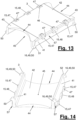
- the multi-part plug connector (1) has a locking device (14) and a separate guide device (13) of the connector parts (2, 3) that is spatially and functionally separated therefrom.
- the locking device (14) is formed by two or more locking elements (16, 18) on the connector parts (2, 3), each of which preferably interacts in a form-fitting manner.
- the guide device (13) is formed by two or more guide elements (15, 17) that preferably interact in a form-fitting manner. formed on the connector parts (2,3).
- the said locking elements (16,18) and the guide elements (15,17) are arranged at a spatial distance from one another and are functionally separated from one another.
- the guide elements (15,17) are arranged in a direction transverse to the longitudinal axis (4) and transverse to the shell base at a distance above the locking elements (16,18).
- the guide elements (15,17) are arranged in front of the locking elements (16,18) in the plug-in direction (65) and have a guiding function.
- the guide elements (15,17) are in Figure 1 at the connector center (5) and on both sides of the connector center (5) on both legs (6,7) as well as on both long sides of the connector (1).
- the guide elements (17) of the plug-in shell are arranged on the free edge (21) of the shell webs (20). They are designed as recesses on the free edge (21) and have an access opening pointing away from the shell base (19).
- the recesses (30) are each arranged between the center finding and the retaining element (27) following in the direction of the adjacent end face (38).
- the recess (30) is each arranged as a free space between the front edge of the retaining element (27) and the back of the center finding (33).
- An associated or cooperating guide element (15) on the bridge (3) can penetrate into this recess (30) when the connector parts (2, 3) are plugged together.
- the central guide element (17) at the connector center (5) is also designed as an upwardly open recess (35) at the free edge (31) of the respective shell web (20).
- the recess (35) is located at the center finding (33), which in the embodiment shown is formed by two stop lugs (34), each are aligned towards the connector centre (5) and are angled outwards.
- the guide elements (15) on the bridge (3) are each designed as a side projection (47, 48) that protrudes laterally.
- the guide elements (15) are designed and positioned on the bridge (3) in such a way that they protrude into their associated recess (30, 35) when the connector parts (2, 3) are plugged together.
- the guide elements (15) of the bridge (3) preferably fill the recesses (30, 35) at least to a large extent. They have a corresponding height and lateral projection.
- the recesses (30) on the retaining elements (27) each have an upright and preferably straight stop edge (31) which extends transversely to the shell base (19) and in the plugging direction (65) of the connector parts (2,3).
- the stop edge (31) is formed by an upright web edge. It is arranged on the legs (6,7) on the side of the recess (30) facing the connector center (5).
- the associated guide elements (15) or projections (47) on the bridge (3) rest with a stop side (47') on the associated stop edge (31) or are at least immediately adjacent to it.
- the stop side (47') is designed, for example, as a flat end wall on the side of the respective guide element (15) facing the connector center (5).
- the straight stop side (47') also extends transversely to the shell base (19) and in the plug-in direction (65) of the connector parts (2,3).
- the respective cooperating guide elements (15,17) on the two legs (6,7) form a two-sided stop function for the assembled connector parts (2,3), which can be moved along the longitudinal axis (4) in both directions acts like a clamp.
- the connector parts (2,3) are precisely aligned and positioned relative to one another by this stop function.
- the middle guide element (15) or the middle projection (48) engages in the central recess (35) between the stop lugs (34) when the connector parts (2,3) are put together.
- the guide device (13) can also have a supporting function for the connector parts (2, 3) that are plugged together.
- the recesses (30, 35) on the free edges (21) of the shell webs (20) have a lower edge (32) that preferably extends parallel to a main plane of the shell base (19).
- the guide elements (15, 17) on the bridge and plug-in shell can be coordinated with one another in such a way that the guide elements (15) or lateral projections (47, 48) rest on the lower edge (32) of the relevant recess (30, 35) and are supported there.
- the lower edge (32) forms a supporting edge.
- the lower edge (32) can have a groove or depression in the middle that is adapted to the contour of the central lateral projection (48) and receives it in a form-fitting manner in the stop position. This can form an additional axial guide and stop function.
- the guide elements (15) or side projections (47, 48) are arranged on the outside of the bridge in its upper area. They can be located on a connecting roof (42) and/or on a lateral bridge web (41).
- the guide device (13) has a guiding function for the locking device (14) explained below.
- the interacting guide elements (15,17) of bridge and plug-in shell in mutual guiding engagement before the locking device (14) is found and closed.
- the guiding function facilitates the plugging together and mutual positioning of the connector parts (2,3).
- the cooperating locking elements (16,18) of the locking device (14) are in the embodiment of Figures 1 to 17 also arranged on the bridge (3), in particular the lateral bridge webs (41), and on the shell webs (20).
- a locking element (18) of the plug-in shell is designed as a latching opening (36) on a shell web (20).
- four latching openings (36) are arranged on both sides and at a distance from the connector center (5) on the legs (6, 7) and the shell webs (20).
- the latching openings (36) are each designed as a through-opening in the wall of the connector web (20) and are arranged at a distance above the shell base (19).
- the latching openings (36) have a rectangular shape, for example in the side view.
- the latching openings (36) are arranged at a distance below the guide elements (17) on the free edge (21) of the relevant shell web (20).
- An associated locking element (16) of the bridge is designed as a lateral locking projection (49) which, when the connector parts (2, 3) are in the plug-in position, engages the associated locking opening (36) from the inside in a form-fitting manner.
- a guide and support function can be formed in addition to the locking function.
- the guide function can exist in the longitudinal direction (4) and transversely thereto.
- a support function can be provided against transverse forces in the direction of the shell base (19).
- the respective lateral locking projection (49) is designed as a locking lug (50) which has an oblique shape and is angled towards the bridge roof (42).
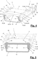
- Figure 4 and 17 illustrate this design and the interaction with the respective locking opening (36).
- the locking projection (49) or the locking lug (50) engages in a form-fitting, preferably spring-fitting manner in the associated locking opening (36).
- the locking lug (50) can slide along the facing shell web (20) due to the oblique bend and the likewise oblique outer wall when the bridge is plugged in and can elastically deflect due to a bridge deformation and can spring back again when the locking opening (36) is reached and engage there in a form-fitting manner.
- Figure 16 shows this situation.
- the spring nose (50) can rest with its underside (52) on a lower edge of the locking opening (36).
- the spring nose (50) can rest with its upper side (51) on the upper edge of the locking opening (36).
- the locking device (40) allows the inserted bridge to be supported on the shell web (20) in a floating manner and at a distance above the shell base (19) and secured against lifting.
- the locking projection (49), in particular the latching nose (50), can be arranged on a lower edge of a lateral bridge web (41).
- the four locking projections (49) or latching noses (50), for example, can be arranged on the corner areas of the bridge.
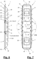
- Figure 5 and 13 to 17 also illustrate that one or both lateral bridge webs (41) can have a wedge-shaped outer contour (57) that widens in the direction of the bridge roof (42).
- the outer contour (57) can be located in the middle area of the bridge web(s) (41) between the locking projections (49) or locking lugs (50).
- the outer contour (57) is adapted, for example, to an outwardly directed inclination of the associated shell web (20) and can rest against it.
- the shell webs (20) can support each other via the said system and the bridge (3).
- the bridge web area above the locking lugs (50) is designed with parallel walls, which is favorable for the said web deformation when plugging in.
- the connector part (3) or the bridge can have a surface on the outside of the bridge roof (42) that is essentially of any shape and preferably adapted to the contour of the hollow profile (11).
- the outer surface of the bridge roof (42) is largely flat and is aligned parallel to the shell base (19) in the plug-in position.
- one or more roof projections (46) protruding from the surface can be arranged on one or both longitudinal edges of the bridge or the bridge roof (42). These can be designed as studs, for example, and can be lined up one behind the other in a straight line in the direction of the longitudinal axis (4). In another embodiment, a single, beam-shaped roof projection can be present instead of a row of studs. The roof projection(s) (46) can also be omitted.
- the connector part (3) or the bridge can have a bulging and, for example, rounded roof recess (44) on one or both front sides when viewed in the longitudinal direction (4) and, if necessary, a roof slope (43) sloping from the roof surface to the front edge of the roof.
- the roof slope (43) can extend over the entire width of the bridge, leaving out the roof recess (44).
- the roof recess (44) can be arranged in the middle and extend over only part of the width of the bridge.
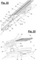
- FIG 18 shows a plug connection (8) which consists of the above-described multi-part plug connector (1) according to Figures 1 to 17 and a hollow profile (11).
- the plug connection (8) is also in Figures 20 to 23 shown in various frontal views and longitudinal sections.
- the hollow profile (11) has a profile base (61), an opposite profile roof (60) and profile side walls (62) arranged between them, which enclose a hollow interior of the hollow profile (11).
- Figure 19 In the installation position shown in an insulating glazing (9), the profile base (61) and the shell base (19) of the plug connector (1) face the interior of the pane.
- the profile roof (60) and the bridge (3) face the outside of the spacer (10) and the insulating glazing (9).
- the shell base (19) rests on the profile base (61) of the hollow profile (11) plugged onto one or both legs (6,7).
- the hollow profile (11) is designed as a warm-edge hollow profile. It is designed as a composite body made of plastic and metal.
- the hollow profile (11) can, for example, comprise a profile body (58) made of plastic with a U-shaped cross-section, which Profile base (61) and the profile side walls (62).
- the hollow profile (11) can also comprise a profile shell (59) which covers the upward opening of the profile body (58) and forms the profile roof (60).
- the profile shell (59) can be made of metal, in particular of heat-insulating stainless steel.
- the profile shell (59) can also encompass the profile body (58) and its side walls on the outside and can be held in a form-fitting manner in a clip groove on the lower area of the profile body (58) on both sides, for example with a lower shell edge.
- One or more roof deformations (63) can be arranged on the profile roof (60). These can be designed, for example, as a rib structure or as a corrugated sheet structure.
- An axial roof web (64) can also be arranged on the longitudinal edges of the profile roof (60) and, if applicable, the profile shell (59), which is open at the bottom and has a curvature directed upwards or towards the outside of the hollow profile.
- the roof projections (46) of the inserted connector (1) can be accommodated in the hollow roof web (64).
- the attached hollow profile (11) can be pushed to the center (33) and to an opposing stop lug (34).
- the stop lug (34) located in front of the connector center (5) in the attachment direction is passed over and gives way in a spring-loaded manner, with the stop lug (34) located beyond the connector center (5) serving with its front side as a stop for the hollow profile (11).
- the other hollow profile or hollow profile end is then attached to the other connector leg and pushed to the front stop on the first hollow profile (11).
- the joint of the hollow profiles or hollow profile ends (11) is located at the connector center (5) and is tightly closed.
- the plugged-in connector (1) bridges the joint (12) with both connector parts (2,3).
- a granulated drying agent can flow through the shell and bridge cavities (39,45) and through the connector (1). In the area of the joint (12) it is prevented from escaping from the connector (1) and at the joint (12) by the plugged-in connector parts (2,3).
- a sealing agent (66) on the connector (1) according to Figure 24 can additionally seal the joint (12).
- the retaining elements (26,27,28) directed in the plugging direction and towards the connector center (5) are passed over and give way in a spring-loaded manner.
- Figures 9 to 12 illustrate an example of a design of the connector part (2) designed as a plug-in shell.
- the connector part (2) is designed, for example, as a metal part, in particular as a stamped and bent part made of sheet steel. Alternatively, it can be made of plastic or another material.
- the connector part (2) is used for insertion and fixing in the attached hollow profiles (11). It has the aforementioned connector legs (6,7) and the previously described centering (33). On the shell webs (20) on both sides of the connector center (5) there are outwardly curved web embossings (25) which are located on the legs (6,7) and which have a sealing effect against the adjacent hollow profile side walls (62) and prevent desiccant flow through the connector center (5).
- retaining elements (26, 27) of the type described above are arranged axially one behind the other. They all have, for example, the aforementioned rectangular shape. Alternatively, a different shape, e.g. a wedge shape, is possible.
- the retaining elements (26) closest to the front face (38) are arranged lower and at a smaller distance above the shell base (19) than the retaining elements (27) following in the direction of the connector center (5).
- the upper and, if applicable, lower edges of these retaining elements (27) are at the same height below one another.
- the above-mentioned design can also be modified.
- the retaining elements (26, 27) are cut free from the shell web (20), for example by a web cutout (29), and bent outwards at an angle.
- the web cutout (29) has a greater axial length than the retaining elements (26, 27). This creates a free space in each case.
- the retaining elements (27) arranged on both legs (6, 7) adjacent to the connector center (5) the free space forms the aforementioned guide element (17) and the recess (30).
- the stop edge (31) is designed as an upright web edge of the shell web area following the connector center (5).
- the aforementioned design of the retaining elements (26,27) and the web cutout (29) has particular advantages for a punched and bent plug-in shell made of metal, but is also suitable for a plug-in shell made of plastic or another material. If the plug-in shell is designed as a cast or injection-molded part, e.g. made of plastic, the shape can be modified by, for example, attaching the retaining elements (26,27) to the outside of the solid shell webs (20) are formed and the recess(es) (30) are introduced separately at the free edges (21) of the shell webs (20).
- the locking elements (18) or the locking openings (36) are arranged on both sides at a distance from the connector center (5) and, for example, beyond the web embossings (25).
- the bottom lips (4) are directed obliquely upwards and have a stepped shape.
- the free lip edges can be slit in the middle, with the edge halves being bent and interlocked relative to each other in height.
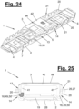
- Figures 24 and 25 show a variant of the connector (1) and its connector parts (2,3).
- the bridge (3) has, for example, a greater height of its bridge webs (41) than in the previously described embodiment.
- the top of the bridge roof (42) protrudes beyond the free edge (21) of the shell webs (20).
- the surface of the bridge roof (42) is flat and has no roof projections.
- a sealant (66) for example a sealant bead made of butyl, can be located on the bridge roof (42) at the connector center (5) and aligned transversely to the longitudinal axis (4).
- the guide and locking device (13, 14) can be designed somewhat differently than in the manner described above, wherein the locking openings (36) have, for example, a circular cross-sectional shape.
- Figure 25 shows in the right half of the picture a previously described design of the locking projection (49) as an angled locking lug (50).
- a design of the locking projection (49) as a locking pin (50') protruding transversely from the bridge web (41) is indicated by hatching.
- the locking pin (50') can, for example, have a largely cylindrical shape. It can have a sloping, slippery bottom.
- the top side of the bridge roof (42) is at the level of or below the upper side web edge (21) when the connector parts (2,3) are inserted.
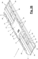
- FIGS. 26 to 33 show another variant of the connector (1). The differences affect both connector parts (2,3).
- the guide device (13) and its respective interacting guide elements (15, 17) on the connector parts (2, 3) can be designed as in the previously described embodiments.
- the locking device (14) is designed differently in this variant.
- the locking device (14) has a stop connection that acts against the plug-in direction (65) and prevents the bridge from being lifted off the plug-in shell.
- a stop (37) is provided as a locking element (18) on the respective shell webs (20), which interacts with one or more stop bumps (53) as locking elements (16) on the bridge and its bridge webs (41).
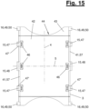
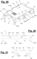
- the plug-in shell has according to Figure 26 , 32 and 33 a different cross-sectional shape than in the previous embodiments.
- the two shell webs (20) each have a cross-sectional shape that is angled several times and divided into several web sections (22, 23, 24).
- a first web section (22) that adjoins the longitudinal edge of the shell base (19) has a shape that bulges outwards. The bulge can be designed as a soft curve or angular.
- a second web section (23) adjoins the upper edge of the web section (22), which has a shape that protrudes laterally into the shell cavity (39).
- a third web section (24) adjoins the second web section (23), which has an upright extension directed transversely to the shell base (19).
- the retaining elements (26, 27) and the centering element (33) can be arranged on the upright web section (24).
- the second and protruding web section (23) forms the said stop (37), which in the plug-in position is supported by the stop hump (53) according to Figure 33 is being undermined.
- Figure 32 shows the position of the two connector parts (2,3) before insertion in the insertion direction (65).
- the stop bumps (53) are arranged on the lower edge of the bridge webs (41). They each have a wedge shape with a sliding side (55) directed diagonally outwards and an upper side (54) which projects transversely to the bridge web (41), which interacts with the stop (37) and forms a stop side.
- a gap or a free space is arranged between the guide element (15) and the upper side (54).
- the stop bumps (53) slide on the shell webs (20) and, while deforming the bridge webs (41), spring inwards into the shell cavity (39), whereby after passing over the re-entrant web sections (23), they spring outwards again and engage behind the stop (37) formed there with the upper side (54).
- the stop bumps (53) can have a support foot (56) on the underside, which stands on the shell base (19) in the plug-in position and supports the bridge (3).
- the support foot (56) can also be omitted, in which case the aforementioned support function of the guide device (13) comes into play.
- the Side projections (47,48) can rest on and strike the lower edges (32) of the recesses (30,35).
- the guide elements (15, 17) and the locking elements (16, 18) are arranged on both shell webs (20) and on both sides of the connector center (5) on both legs (6, 7).
- This arrangement can be modified.
- the central guide elements (15, 17) in the form of the central side projections (48) and the recesses (35) can be omitted. It is also possible to omit one or more guide elements (15, 17) on the legs (6, 7). It is also possible to arrange guide elements (15, 17) on only one leg (6, 7) or on both legs and in each case only on one side of a shell web (20) and with a mutual diagonal offset across the connector center (5).
- the locking elements (16, 18) can also be modified in the same or a similar way. In this case, the design features of the previously described embodiments and in particular of the various designs of the locking device (14) as a latching connection or as a stop connection can also be interchanged and combined with one another.
- lateral projections can be arranged as guide elements (17) on the plug-in shell and associated recesses can be arranged as guide elements (15) on the bridge.
- locking elements (18) on the plug-in shell can be arranged as locking projections, locking lugs or Locking pins can be designed and interact with locking elements (16) in the form of locking openings on the bridge.
- a guide bevel for the spring-loaded deflection of the bridge web when the connector parts (2, 3) are plugged together can be arranged on the top of the locking elements (18).
Landscapes
- Engineering & Computer Science (AREA)
- Civil Engineering (AREA)
- Structural Engineering (AREA)
- Connector Housings Or Holding Contact Members (AREA)
Description
- Die Erfindung betrifft einen mehrteiligen Steckverbinder mit den Merkmalen im Oberbegriff des Hauptanspruchs.
- Ein solcher mehrteiliger Steckverbinder ist aus der
DE 10 2008 048 998 B4 bekannt. Die Brücke ist in die Steckschale lose eingesteckt und mit den Brückenstegrändern am Schalenboden zwischen Bodennoppen und dem benachbarten Schalensteg mit Klemmschluss arretiert. Die Verbindung der zusammengesteckten Verbinderteile ist unsicher. - Die
DE 20 2004 004 734 U1 ,EP 2 027 355 B1 undEP 2 134 916 B1 zeigen andere Formen von mehrteiligen Steckverbindern, bei denen die an der Steckschale eingesteckten Brücken mit dem unteren Rand ihrer seitlichen Brückenstege am Schalenboden aufstehen und mittels seitlicher Noppen der Brückenstege an den Schalenstegen arretiert sind. Die vorspringenden Noppen greifen dabei in Ausnehmungen unterhalb von freigeschnittenen Rückhalteelementen der Schalenstege. Eine separate Führungseinrichtung für die Verbinderteile ist nicht vorhanden. - Die
DE 20 2017 101 315 U1 undEP 1 785 575 A2 zeigen einteilige Steckverbinder ohne eine Brücke. - Es ist Aufgabe der vorliegenden Erfindung, eine verbesserte Steckverbindertechnik aufzuzeigen.
- Die Erfindung löst diese Aufgabe mit den Merkmalen in den selbstständigen Ansprüchen für den Steckverbinder und die Steckverbindung.
- Die beanspruchte Steckverbindertechnik, d.h. der Steckverbinder, seine Verbinderteile, die Steckverbindung und das Verbindungsverfahren haben verschiedene Vorteile.
- Der beanspruchte Steckverbinder weist außer einer Arretiereinrichtung eine zusätzliche Führungseinrichtung seiner Verbinderteile auf. Die Führungseinrichtung ist separat vorhanden. Sie ist örtlich und funktional von der Arretiereinrichtung getrennt.
- Die Führungseinrichtung kann dazu vorgesehen und ausgebildet sein, die Verbinderteile beim Zusammenstecken in einer Steckrichtung und auch in der zusammengesteckten Stellung zu führen. Die Steckrichtung kann quer zum Schalenboden, insbesondere quer zu dessen Hauptebene, ausgerichtet sein. Sie kann bevorzugt senkrecht zum Schalenboden, insbesondere senkrecht zu dessen Hauptebene, ausgerichtet sein. Die Führungseinrichtung kann die zusammengesteckten Verbinderteile in Richtung der Längsachse gegenseitig halten. Die Haltefunktion kann in der zusammengesteckten Endstellung und auch zuvor beim Zusammenstecken der Verbinderteile wirksam sein.
- Die Arretiereinrichtung und die zusätzliche separate Führungseinrichtung haben den Vorteil, dass die zusammengesteckten Verbinderteile, d.h. die Steckschale und die Brücke, eine bessere und exaktere sowie höher belastbare Verbindung miteinander haben. Die Führungseinrichtung verbessert auch die Handhabung und Zuordnung bzw. die gegenseitige Positionierung der Verbinderteile bei ihrem Zusammenstecken. Die korrekte Steckstellung und die Arretiereinrichtung können schneller und sicherer gefunden werden. Diese Vorteile ergeben sich auch für die beanspruchte Steckverbindung.
- Die hohe Belastbarkeit ist besonders günstig beim Einstecken des mehrteiligen Steckverbinders in ein Hohlprofil und den dabei wirkenden Kräften. Dies gilt sowohl beim sogenannten Vorstecken des Steckverbinders an einem Hohlprofil, als auch beim beidseitigen Aufstecken von Hohlprofilen oder Hohlprofilenden auf den Steckverbinder. Die Verbinderteile bleiben dabei in ihrer gegenseitigen Position und werden auch von den Einsteckkräften nicht gegeneinander verschoben oder sogar voneinander gelöst.
- Positive Aspekte ergeben sich für das dichte Zusammenstoßen der Hohlprofilstirnseiten an einer Stoßstelle im Bereich der Verbindermitte, wodurch die Dichtigkeit verbessert wird. Die eingesteckte Brücke befindet sich zumindest im Bereich der Verbindermitte und an der Stoßstelle. Ein Austritt von granuliertem Trocknungsmittel aus einem Hohlprofil an der Stoßstelle in den Innenraum der Isolierverglasung kann mit hoher Sicherheit verhindert werden. Die Gasdichtigkeit wird ebenfalls verbessert.
- Ferner ergeben sich günstige Auswirkungen für eine verbesserte mechanische Stabilität des Steckverbinders gegenüber von außen einwirkenden Kräften oder Momenten, z.B. Biegemomenten beim Transport eines geschlossenen Abstandhalterrahmens. Zugleich wird die Toleranzaufnahmefähigkeit des mehrteiligen Steckverbinders und die Anpassbarkeit an die gegebenen Abmessungen des oder der Hohlprofile verbessert. Toleranzen können bei der Steckverbindung in der Höhe und/oder in der Breite auftreten. Besondere Vorteile bestehen dabei für Warm-Edge-Hohlprofile, die besonders gute wärmedämmende Eigenschaften haben.
- Die Arretiereinrichtung und die separate Führungseinrichtung weisen jeweils zusammenwirkende Arretierelemente und zusammenwirkende Führungselemente auf. Die Arretierelemente und die Führungselemente sind dabei voneinander örtlich distanziert angeordnet und funktional getrennt. Günstig ist ein jeweils formschlüssiges Zusammenwirken der Arretierelemente untereinander und der Führungselemente untereinander.
- Die besagten Führungselemente und die besagten Arretierelemente können mit einem gegenseitigen, quer zur Längsachse und ggf. quer zum Schalenboden des Steckverbinders gerichteten Abstand angeordnet sein. Dementsprechend sind die Arretiereinrichtungen und die Führungseinrichtungen voneinander beabstandet, was für eine besonders günstige Gesamtverbindung der zusammengesteckten Verbinderteile sorgt.
- Die in Steckrichtung bevorzugt vorn liegende Führungseinrichtung kann beim Zusammenstecken der Verbinderteile zuerst wirken und kann eine Leitfunktion für das nachfolgende exakte Zusammentreffen und Schließen der zusammenwirkenden Arretierelemente und der Arretierfunktion haben. Die Führungseinrichtung kann beim Zusammenstecken der Verbinderteile leicht gefunden und geschlossen werden. Sie hat auch eine Positionierfunktion für die Verbinderteile
- Für die Leit- und Führungsfunktion ist es günstig, wenn die zusammenwirkenden Führungselemente jeweils eine Anschlagkante und eine zugeordnete Anschlagseite aufweisen, die zu Führungszwecken zusammenwirken und jeweils quer zum Schalenboden ausgerichtet sind. Insbesondere können die Anschlagkanten und Anschlagseiten der zusammenwirkenden Führungselemente parallel zueinander und bevorzugt längs der Steckrichtung ausgerichtet sein. Sie können auch schräg zur Steckrichtung ausgerichtet sein.
- In einer vorteilhaften Ausgestaltung haben die jeweils zusammenwirkenden Führungselemente einen größeren Abstand vom Schalenboden des Steckverbinders als die jeweils zusammenwirkenden Arretierelemente. Vorteilhaft ist ferner eine Anordnung der jeweils zusammenwirkenden Führungselemente und der jeweils zusammenwirkenden Arretierelemente im Bereich einer axialen Verbindermitte des Steckverbinders.
- Die eingesteckte Brücke befindet sich zumindest im Bereich der Verbindermitte. Sie kann sich hiervon ausgehend entlang der Längsachse nach beiden Richtungen erstrecken. Die Brücke kann wesentlich kürzer als die Steckschale sein und kann vor allem an der Stoßstelle und im benachbarten beidseitigen Umgebungsbereich der Hohlprofile wirken. Der Steckverbinder kann sich in zwei Verbinderschenkel gliedern, die von der Verbindermitte ausgehend sich entlang der Längsachse nach verschiedenen Richtungen erstrecken. Der mehrteilige Steckverbinder ist bevorzugt als gerader Steckverbinder ausgebildet. Er kann alternativ eine abgewinkelte Form haben und als Eckverbinder gestaltet sein.
- Die Führungseinrichtung, insbesondere die zusammenwirkenden Führungselemente, können dazu ausgebildet sein, die zusammengesteckten Verbinderteile in Richtung der Längsachse gegenseitig zu halten. Dies kann mit einer Anschlagfunktion, insbesondere einer bevorzugt zweiseitigen Anschlagfunktion erfolgen. Die Führungseinrichtung und die Führungselemente können dabei eine begrenzte relative Beweglichkeit der Verbinderteile in Richtung der Längsachse zulassen.
- In einer bevorzugten Ausführungsform positionieren die Führungseinrichtung und die Führungselemente die zusammengesteckten Verbinderteile mit einer Anschlagfunktion, die zweiseitig in Richtung der Längsachse wirkt. Die Brücke und die Steckschale können dadurch eine vorgegebene und exakte gegenseitige Position haben, die spielfrei oder zumindest spielarm eingenommen werden kann. Dies ist günstig für die Aufnahme von Kräften und Widerständen beim Einstecken des Steckverbinders in ein Hohlprofil und für die erwähnte Leitfunktion.
- Die besagten Führungselemente und die Führungseinrichtung können in einer vorteilhaften Ausgestaltung die zusammengesteckten Verbinderteile in einer Richtung quer zur Längsachse und ggf. quer zum Schalenboden gegenseitig gegen Druckkräfte abstützen. Dies ist vor allem bei der Aufnahme von Höhentoleranzen des oder der Hohlprofile durch den Steckverbinder von Vorteil. Derartige Druckkräfte werden häufig von außen auf die Brücke eingeleitet und sind gegen den Schalenboden der Steckschale gerichtet. Die Abstützfunktion der Führungseinrichtung kann zusätzlich zu einer Abstützfunktion der Arretiereinrichtung vorhanden sein oder kann eine evtl. fehlende Abstützfunktion der Arretiereinrichtung ersetzen.
- Die zusammenwirkenden Arretierelemente und die Arretiereinrichtung können ein Abheben und Lösen der zusammengesteckten Verbinderteile zumindest in einer Richtung quer zur Längsachse des Steckverbinders, insbesondere entgegen der Steckrichtung, verhindern. Dies kann durch eine Anschlagverbindung oder eine Rastverbindung erfolgen. Die Arretierelemente und die Arretiereinrichtung können die zusammengesteckten Verbinderteile auch gegenseitig in einer Richtung entlang und quer zur besagten Längsachse und ggf. quer zum Schalenboden positionieren und/oder abstützen. Hierfür ist eine Ausgestaltung der Arretiereinrichtung als formschlüssige Rastverbindung von Vorteil. Die Arretierelemente sowie die Arretiereinrichtung können ferner die Brücke mit Kontakt oder bevorzugt mit Abstand zum Schalenboden in einer Richtung quer zur Längsachse abstützen.
- Die Führungseinrichtung und die Arretiereinrichtung sowie deren jeweils zusammenwirkenden Führungselemente und Arretierelemente können bzgl. der Verbinderteile unterschiedlich ausgebildet und angeordnet sein. Günstig ist bei der Steckschale eine jeweilige Anordnung der ein oder mehreren Führungselemente und der ein oder mehreren Arretierelemente an einem oder beiden Schalenstegen.
- Bei der Brücke können die ein oder mehreren Führungselemente und die ein oder mehreren Arretierelemente jeweils an einer oder beiden Längsseiten, vorzugsweise außenseitig an ein oder beiden Brückenstegen, angeordnet sein. Das oder die Führungselemente können in der Nähe des Brückendachs und das oder die Arretierelemente mit Abstand unter dem Brückendach angeordnet sein. Bei zusammengesteckten Verbinderteilen sind die jeweils zusammenwirkenden Arretierelemente unterhalb der jeweils zusammenwirkenden Führungselemente und mit größerer Nähe zum Schalenboden angeordnet.
- Ein oder mehrere der jeweils zusammenwirkenden Führungselemente der Brücke und der Steckschale können an der Verbindermitte und/oder an zumindest einem der beidseits axial angrenzenden Verbinderbereichen bzw. Verbinderschenkeln angeordnet sein. Eine Anordnung an der Verbindermitte hat den Vorteil einer Stabilisierung und Abstützung des Steckverbinders und seiner Verbinderteile an der Verbindermitte und ist auch günstig für eine zentrierende Leitfunktion beim Zusammenstecken der Verbinderteile.
- In einer vorteilhaften Ausgestaltung können bei einer Steckschale das oder die Führungselemente an einem freien Rand von einem oder beiden Schalenstegen angeordnet sein. Die Arretierelemente können am Schalensteg mit Abstand unter dem freien Rand angeordnet sein. Die ein oder mehreren Führungselemente der Steckschale können jeweils als eine Ausnehmung am freien Rand des oder der Schalenstege ausgebildet sein und eine vom Schalenboden wegweisende Zugangsöffnung haben. Hier können das oder die Führungselemente an der Brücke beim Zusammenstecken der Verbinderteile eingeführt werden. Die Ausnehmung kann z.B. in der Seitenansicht eine U-Form oder V-Form oder eine andere geeignete Formgebung haben.
- Die Führungseinrichtung kann ein zentrales Führungselement an der Verbindermitte mit einseitiger oder beidseitiger Anordnung am Steckverbinder umfassen. Dies ist für eine zentrale Relativpositionierung und auch Abstützung der Verbinderteile von Vorteil. Ein zentrales Führungselement kann als Ausnehmung zwischen federnden Anschlagnasen einer einseitigen oder beidseitigen Mittenfindung angeordnet sein.
- Alternativ oder zusätzlich kann die Führungseinrichtung ein oder mehrere dezentrale Führungselemente, insbesondere Ausnehmungen, aufweisen. Diese können zwischen der Mittenfindung und einem benachbarten Rückhalteelement an einem freien Rand des oder der Schalenstege angeordnet sein. Ein oder mehrere Ausnehmungen können auch mit größerem Abstand von der Verbindermitte zwischen benachbarten Rückhalteelementen an einem freien Rand des Schalenstegs angeordnet sein.
- Günstig ist bei diesen verschiedenen Ausgestaltungen, wenn ein oder mehrere Führungselemente der Brücke jeweils als seitlich abstehender Seitenvorsprung ausgebildet sind und in eine der besagten Ausnehmungen ragen. Ein oder mehrere Führungselemente der Brücke können außerdem zur Erfüllung der vorgenannten Stützfunktion der Führungseinrichtung an einer Unterkante einer Ausnehmung abgestützt sein und hier anliegen. Dies ist vor allem günstig, wenn die Arretiereinrichtung nur eine Anschlagfunktion hat, die gegen das gegenseitige Abheben der Verbinderteile quer zur besagten Längsachse wirkt. Daneben sind andere konstruktive und funktionale Ausgestaltungen von Führungselementen der Brücke möglich.
- Die Arretiereinrichtung und die jeweils zusammenwirkenden Arretierelemente können in der vorerwähnten Weise unterschiedlich ausgebildet und angeordnet sein. Ein Arretierelement der Steckschale kann z.B. als Rastöffnung an einem Schalensteg ausgebildet sein. Ein anderes Arretierelement der Steckschale kann z.B. als Anschlag an einem Schalensteg gestaltet sein und fungieren.
- Die Rastöffnung ermöglicht ein formschlüssiges und rastendes Zusammenwirken mit einem Arretierelement an der Brücke. Hierbei kann auch eine Führungs- und Abstützfunktion bestehen. Die Rastöffnung kann mit Abstand unterhalb des oder der Führungselemente bzw. Ausnehmungen am freien Rand des Schalenstegs und mit Abstand über dem Schalenboden angeordnet sein. Die eingesteckte Brücke kann dadurch vom Schalenboden distanziert und an der Rastöffnung abgestützt werden.
- Ein Arretierelement der Brücke kann als seitlicher Arretiervorsprung ausgebildet sein, der quer von der Brücke absteht und formschlüssig in die zugeordnete Rastöffnung an einem Schalensteg eingreift. Für die Ausbildung des Arretiervorsprungs gibt es verschiedene Möglichkeiten. Besonders günstig ist eine Ausbildung als Rastnase, die schräg und in Dachrichtung abgewinkelt ist. Diese Rastnasenform kann ein Angleiten der Rastnase am Schalensteg beim Zusammenstecken der Verbinderteile mit Brückenverformung und anschließendem Einschnappen der Rastnase in die Rastöffnung bewirken. In der Rastöffnung kann sich die Rastnase mit ihrer Unterseite an einem unteren Rand der Rastöffnung abstützen. Mit ihrer Oberseite kann sie an einem oberen Rand der Rastöffnung anliegen oder eng benachbart sein. Hierdurch kann ein Abheben der Brücke entgegen der Steckrichtung verhindert werden.
- Die Rastöffnung und der zugeordnete seitliche Arretiervorsprung können in der Form variieren und aufeinander abgestimmt sein. Die Rastöffnung kann z.B. eine kreisrunde, ovale oder prismatische Querschnittsform mit ggf. gerundeten Ecken haben. Der seitliche Arretiervorsprung kann z.B. als seitlich von der Brücke abstehender Rastzapfen ausgebildet sein. Der Rastzapfen kann z.B. eine zylindrische oder quaderartige Form mit parallel zueinander sowie zum Schalenboden ausgerichteten Seitenwänden haben. Die Unterseite kann zum besagten Angleiten schräg ausgerichtet sein.
- Die vorgenannten Ausgestaltungen und Funktionen der Rastnase und des Rastzapfens sind auch mit anderen konstruktiven Gestaltungen eines Arretiervorsprungs möglich.
- Günstig ist außerdem eine keilförmige und in Richtung zum Brückendach sich erweiternde Außenkontur eines seitlichen Brückstegs. Die Außenkontur kann an einen schräg nach außen gerichteten Schalensteg angepasst sein, so dass der Brückensteg mit der keilförmigen Außenkontur und der Schalensteg plan aneinander liegen können. Dies ist günstig für die Stabilität des Steckverbinders und der Steckverbindung.
- Bei einer anderen Ausgestaltung der Arretiereinrichtung als Anschlagverbindung kann ein Arretierelement der Steckschale als seitlich in den Schalenhohlraum einspringender Anschlag an einem Schalensteg ausgebildet sein. Der Anschlag kann insbesondere von einem entsprechend einspringenden Stegabschnitt eines mehrfach abgewinkelten und in mehrere Stegabschnitte untergliederten Schalenstegs gebildet werden. Die beanspruchte Gestaltung und Anordnung der Stegabschnitte ist vorteilhaft für eine Aufnahme von Seiten- oder Breitentoleranzen und Höhentoleranzen. Der betreffende Schalensteg kann zur Toleranzaufnahme kontrolliert und ohne nachteilige oder unerwünschte Verformungen federn.
- Bei einer Anschlagverbindung kann ein Arretierelement der Brücke als seitlich vorspringender Anschlaghöcker ausgebildet und bevorzugt am unteren Rand von einem oder beiden Brückenstegen angeordnet sein. Der bevorzugt keilförmige Anschlaghöcker kann bei einem Zusammenstecken der Verbinderteile ebenfalls federnd ausweichen und dann formschlüssig den besagten Anschlag am Schalensteg hintergreifen. Der Anschlaghöcker kann an der Unterseite auch einen Stützfuß aufweisen, der eine Abstützung der Brücke am Schalenboden ermöglicht. Alternativ oder zusätzlich kann die erwähnte Stützfunktion der Führungseinrichtung genutzt werden.
- Die Brücke kann am Brückendach in Längsrichtung gesehen stirnseitig eine einbauchende und bevorzugt gerundete Dachausnehmung aufweisen. Sie kann auch eine zum Dachrand abfallende Dachabschrägung in diesem Bereich umfassen. Dies ist vorteilhaft um beim Aufstecken eines Hohlprofils eventuelle Verformungen an der zum Brückendach benachbarten Hohlprofilwand, insbesondere einem Profildach, aufzunehmen und auszurichten. Solche Verformungen können z.B. beim Abtrennen eines Hohlprofils von einem Profilstrang entstehen. Die Ausrichtfunktion von Dachausnehmung und/oder Dachabschrägung kann den betreffenden Profildachbereich in die gewünschte Soll-Lage bringen und für einen dichten Zusammenschluss der Profilstirnseiten an der Stoßstelle sorgen.
- Die Brücke kann ein außenseitig ebenes Brückendach aufweisen. In einer anderen Ausgestaltung können am Brückendach in Längsrichtung und an ein oder beiden Randseiten jeweils ein oder mehrere, ggf. axial aufgereihte, Dachvorsprünge angeordnet sein. Diese können in hohle Dachstege eines Hohlprofils eingreifen. Sie können einen unerwünschten Durchfluss von granulierten Trocknungsmittel verhindern und können außerdem eine Führungsfunktion haben. Am Brückendach kann auch ein Dichtmittel, z.B. ein quer zur Längsachse des Steckverbinders ausgerichteter Dichtstreifen, angeordnet sein. Das Dichtmittel kann sich bei der Steckverbindung an der Stoßstelle des oder der Hohlprofile befinden. Das Brückendach selbst kann nahe am Profildach ohne Kontakt angeordnet sein oder kann am Profildach druckarm anliegen.
- Die Steckschale kann verschiedene und in Mehrzahl vorhandene Rückhalteelemente aufweisen, die z.B. am freien Rand des oder der Schalenstege und/oder am Schalenboden angeordnet sind. Bei den am freien Rand des oder der Schalenstege angeordneten Rückhalteelementen ist eine in Seitenansicht rechteckige Form von Vorteil, insbesondere für einen optimalen Rückhalt in einem aufgesteckten Hohlprofil, insbesondere einem Warm-Edge-Hohlprofil. Die rechteckigen Rückhalteelemente können parallele Ober- und Unterkanten und eine aufrechte Vorderkante aufweisen. Die parallelen Ober- und Unterkanten können sich parallel zur Hauptebene des Schalenbodens erstrecken.
- Die Verbinderteile des beanspruchten Steckverbinders können aus gleichen oder unterschiedlichen Materialien bestehen. Für den Steckverbinder ist es günstig, wenn die Brücke als Kunststoffteil und die Steckschale als Metallteil, insbesondere als Stanz- und Biegeteil, ausgebildet sind. Die metallische Stegschale bietet eine hohe mechanische Stabilität in Verbindung mit einer günstigen Federwirkung. Die Ausbildung der Brücke als Kunststoffteil hat den Vorteil einer konstruktiv und herstellungstechnisch einfachen und günstigen Bauform mit Anpassungsmöglichkeiten an die Steckschale. Die Steckschale kann als Standardverbinder ausgebildet sein, der auch für andere Zwecke, insbesondere als Einzelverbinder für Hohlprofile, eingesetzt werden kann.
- Die Verbinderteile können aufeinander abgestimmt sein. Die Verbinderteile stellen jeweils eine eigenständige, separat beanspruchbare Erfindung dar. Die Verbinderteile können einzeln oder als Ensemble hergestellt und geliefert werden. Das Zusammenstecken der Verbinderteile kann beim Hersteller der Verbinderteile oder an anderer Stelle, z.B. bei einem Isolierglashersteller, erfolgen.
- Das Hohlprofil ist bevorzugt als Warm-Edge-Hohlprofil ausgebildet. Es kann einen Profikorpus aus Kunststoff und eine Profilschale aus Metall, insbesondere Edelstahl, aufweisen. Das Hohlprofil kann aber auch eine beliebig andere Ausgestaltung als reines Kunststoffprofil oder reines Metallprofil, z.B. gezogenes oder gerolltes Metallprofil, haben.
- In den Unteransprüchen sind weitere vorteilhafte Ausgestaltungen der Erfindung angegeben.
- Der Steckverbinder und die Steckverbindung können folgende vorteilhafte Ausgestaltungen haben. Diese können jeweils einzeln oder in beliebiger Kombination untereinander und mit den beanspruchten Ausbildungen benutzt werden.
- An den Verbinderteilen können jeweils zusammenwirkende Führungselemente und jeweils zusammenwirkende Arretierelemente mit einem gegenseitigen, quer zur Längachse gerichteten Abstand angeordnet sein. Die jeweils zusammenwirkenden Führungselemente können in Steckrichtung vor den jeweils zusammenwirkenden Arretierelemente angeordnet sein.
- Die jeweils zusammenwirkenden Führungselemente und die jeweils zusammenwirkenden Arretierelemente können im Bereich einer axialen Verbindermitte des Steckverbinders angeordnet sein.
- Die zusammenwirkenden Führungselemente können dazu ausgebildet sein, die Verbinderteile beim Zusammenstecken entlang der Steckrichtung zu führen und zu leiten. Sie können insbesondere ein gegenseitiges Verrutschen in Längsrichtung des Steckverbinders vermeiden.
- Die zusammenwirkenden Führungselemente können dazu ausgebildet sein, die zusammengesteckten Verbinderteile in Richtung der Längsachse gegenseitig mit bevorzugt zweiseitiger Anschlagfunktion zu halten und vorzugsweise zu positionieren. Diese Haltefunktion und ggf. Positionierfunktion kann beim Zusammenstecken und in der Steckposition wirksam sein.
- Die Führungseinrichtung, insbesondere die zusammenwirkenden Führungselemente, kann/können dazu ausgebildet sein, die zusammengesteckten Verbinderteile in einer Richtung quer zur Längsachse gegenseitig gegen Druckkräfte abzustützen.
- Die zusammenwirkenden Führungselemente können jeweils eine Anschlagkante und eine Anschlagseite aufweisen, die zu Führungszwecken zusammenwirken und jeweils quer zum Schalenboden ausgerichtet sind. Die Anschlagkanten und Anschlagseiten der zusammenwirkenden Führungselemente können parallel zueinander und bevorzugt längs der Steckrichtung ausgerichtet sein.
- Die zusammenwirkenden Arretierelemente können dazu ausgebildet sein, ein Abheben und Lösen der zusammengesteckten Verbinderteile entgegen der Steckrichtung zu verhindern. Die zusammenwirkenden Arretierelemente können dazu ausgebildet sein, die zusammengesteckten Verbinderteile entlang und quer zur Längsachse zu positionieren und/oder abzustützen. Die zusammenwirkenden Arretierelemente können dazu ausgebildet sein, die Brücke mit Kontakt oder mit Abstand zum Schalenboden in Steckrichtung abzustützen.
- Ein oder mehrere Führungselemente und ein oder mehrere Arretierelemente der Steckschale können jeweils an einem oder beiden Schalenstegen angeordnet sein. Ein oder mehrere Führungselemente und ein oder mehrere Arretierelemente der Brücke können jeweils an einer oder beiden Brückenlängsseiten, insbesondere außenseitig an ein oder beiden Brückenstegen, angeordnet sein.
- Das oder die Führungselemente der Brücke können in der Nähe des Brückendachs und das oder die Arretierelemente der Brücke können mit Abstand unter dem Brückendach angeordnet sein.
- An der axialen Verbindermitte und/oder an den beidseits axial angrenzenden Verbinderbereichen können jeweils zusammenwirkende Führungselemente der Brücke und der Steckschale angeordnet sein.
- Das oder die Führungselemente der Steckschale können an einem freien Rand des Schalenstegs angeordnet sein. Das oder die Arretierelemente der Steckschale können am Schalensteg mit Abstand unter dem freien Rand des Schalenstegs angeordnet sein.
- Ein oder mehrere Führungselemente der Steckschale können jeweils als eine Ausnehmung am freien Rand des Schalenstegs mit einer vom Schalenboden wegweisenden Zugangsöffnung ausgebildet sein. Eine oder mehrere Ausnehmungen an der Steckschale können eine aufrechte Stegkante aufweisen, die eine Anschlagkante bildet und die für eine Anschlagfunktion mit einer Anschlageseite des zugeordneten Führungselements der Brücke zusammenwirkt. Eine oder mehrere Ausnehmungen können zwischen einer Mittenfindung und einem benachbarten Rückhalteelement an einem freien Rand des Schalenstegs angeordnet sein. Ein oder mehrere Ausnehmungen können zwischen benachbarten Rückhalteelementen an einem freien Rand des Schalenstegs angeordnet sein. Eine Ausnehmung kann an der axialen Verbindermitte zwischen Anschlagnasen der Mittenfindung angeordnet sein.
- Ein oder mehrere Führungselemente der Brücke kann/können jeweils als seitlich abstehender Seitenvorsprung ausgebildet sein und beim Zusammengestecken der Verbinderteile sowie in deren Steckstellung in eine zugeordnete Ausnehmung der Steckschale ragen. Die ein oder mehrere Führungselemente der Brücke kann/können an einer Unterkante der Ausnehmung abgestützt sein.
- Ein Arretierelement der Steckschale kann als Rastöffnung an einem Schalensteg ausgebildet sein. Die Rastöffnung kann mit Abstand unterhalb des oder der Führungselemente an einem freien Rand des Schalenstegs und mit Abstand über dem Schalenboden angeordnet sein.
- Ein Arretierelement der Brücke kann als seitlicher Arretiervorsprung, insbesondere als schräg in Dachrichtung abgewinkelte Rastnase oder als quergerichteter Rastzapfen, ausgebildet sein. Ein Arretiervorsprung der Brücke, insbesondere die Rastnase oder der Rastzapfen, kann dazu ausgebildet sein, beim Zusammenstecken der Verbinderteile formschlüssig und bevorzugt federnd in die zugeordnete Rastöffnung eingreifen. Ein Arretiervorsprung der Brücke, insbesondere die Rastnase oder der Rastzapfen, kann dazu ausgebildet sein, sich mit seiner Unterseite an einem unteren Rand der Rastöffnung abzustützen. Ein Arretiervorsprung der Brücke, insbesondere die Rastnase oder der Rastzapfen, kann an einem unteren Rand, insbesondere im Eckbereich, eines seitlichen Brückenstegs angeordnet sein.
- Ein seitlicher Brückensteg kann im mittleren Bereich eine keilförmige, in Richtung zum Brückendach sich erweiternde Außenkontur aufweisen. Die erweiternde Außenkontur kann an einen schräg nach außen gerichteten Schalensteg angepasst sein.
- Ein Arretierelement der Steckschale kann als seitlich in den Schalenhohlraum einspringender Anschlag am Schalensteg ausgebildet sein. Der Schalensteg kann eine mehrfach abgewinkelte und in mehrere Stegabschnitte untergliederte Querschnittsform aufweist, wobei ein Stegabschnitt einen Anschlag am Schalensteg bildet. Ein seitlich in den Schalenhohlraum einspringender Stegabschnitt ksnn einen Anschlag am Schalensteg bilden.
- Ein erster seitlich am Rand des Schalenbodens anschließender Stegabschnitt kann eine seitlich nach außen ausbauchende Form haben. Ein daran anschließender zweiter Stegabschnitt kann eine seitlich in den Schalenhohlraum einspringende Form aufweisen. Ein ggf. daran anschließender Stegabschnitt kann eine aufrechte und quer zum Schalenboden gerichtete Erstreckung aufweisen.
- Ein Arretierelement der Brücke kann als seitlich vorspringender Anschlaghöcker ausgebildet sein. Der Anschlaghöcker kann dazu ausgebildet sein, beim Zusammenstecken der Verbinderteile formschlüssig und bevorzugt federnd einen Anschlag am Schalensteg zu hintergreifen. Der Anschlaghöcker kann eine obere Anschlagseite und eine keilförmige, in Richtung zum Brückendach sich erweiternde Gleitseite aufweisen. Der Anschlaghöcker kann an der Unterseite einen Stützfuß aufweisen, der zur Abstützung am Schalenboden ausgebildet sein kann. Der Anschlaghöcker kann an einem unteren Rand, insbesondere im Eckbereich, eines seitlichen Brückenstegs angeordnet sein.
- Die Brücke kann am Brückendach in Längsrichtung stirnseitig eine einbauchende, bevorzugt gerundete, Dachausnehmung und ggf. eine zum Dachrand abfallende Dachabschrägung aufweisen. Die Brücke kann am Brückendach ein Dichtmittel aufweisen.
- Die Steckschale am freien Rand des oder der Schalenstege kann beidseits der axialen Verbindermitte jeweils mehrere in Längrichtung hintereinander aufgereihte und jeweils seitlich in Richtung zur Verbindermitte ausgestellte Rückhalteelemente aufweisen. Die seitlichen Rückhalteelemente können in der Seitenansicht eine rechteckige Form mit parallelen Ober- und Unterkanten und eine aufrechte Vorderkante aufweisen.
- Die Steckschale an dem oder den Schalenstegen kann beidseits der axialen Verbindermitte jeweils eine nach außen ausbauchende und quer zum Schalenboden ausgerichtete Stegprägung aufweisen.
- Die Brücke kann als Kunststoffteil und die Steckschale als Metallteil, insbesondere als Stanz- und Biegeteil, ausgebildet sein.
- Die Steckverbindung kann den Steckverbinder und ein Hohlprofil von einem Abstandshalter einer Isolierverglasung umfassen Das Hohlprofil kann als Warm-Edge-Hohlprofil ausgebildet sein. Das Hohlprofil kann einen Profilboden, ein gegenüberliegendes Profildach und verbindende Profilseitenwände aufweisen. Der Profilboden und der hier anliegende Schalenboden können in Einbaustellung zum Innenraum der Isolierverglasung weisen. Das Profildach kann einen axialen, nach außen ausbauchenden Dachsteg und/oder eine quer zur Längsachse gerichtete Dachverformung, insbesondere in Form von Rippen, aufweisen. Das Hohlprofil kann einen im Querschnitt U-förmigen Profilkorpus und eine die längslaufende Korpusöffnung übergreifende Profilschale aufweisen. Das Hohlprofil kann aus Kunststoff und aus Metall, insbesondere Edelstahl, ausgebildet sein, wobei bevorzugt der Profilkorpus aus Kunststoff und die Profilschale aus Metall, insbesondere Edelstahl, ausgebildet sein kann.
- Die Erfindung ist in den Zeichnungen beispielhaft und schematisch dargestellt. Im Einzelnen zeigen:
- Figur 1:
- Eine perspektivische Ansicht des mehrteiligen Steckverbinders,
- Figur 2:
- einen vergrößerten Ausschnitt des Steckverbinders von
Figur 1 an dessen mittlerem Bereich, - Figur 3:
- eine perspektivische Ansicht der Verbinderteile vor einem Zusammenstecken in einer Steckrichtung,
- Figur 4 und 5:
- perspektivische Querschnitte des Steckverbinders von
Figur 1 bis 3 , - Figur 6 und 7:
- eine Seitenansicht und eine Draufsicht des Steckverbinders von
Figur 1 bis 5 , - Figur 8:
- einen vergrößerten Ausschnitt VIII von
Figur 7 , - Figur 9:
- eine perspektivische Ansicht einer Steckschale des mehrteiligen Steckverbinders,
- Figur 10 bis 12:
- eine Seitenansicht, Draufsicht und Stirnansicht der Steckschale von
Figur 9 , - Figur 13 bis 15:
- perspektivische Ansichten und eine Draufsicht einer Brücke des mehrteiligen Steckverbinders,
- Figur 16 und 17:
- eine Stirnansicht der Verbinderteile vor und nach dem Zusammenstecken,
- Figur 18:
- eine Steckverbindung eines Hohlprofils und eines mehrteiligen Steckverbinders in perspektivischer Ansicht,
- Figur 19:
- eine Isolierverglasung mit einem Abstandhalterrahmen und einem Steckverbinder sowie einer Steckverbindung in Seitenansicht,
- Figur 20 und 21:
- eine frontale und eine perspektivische Stirnansicht der Steckverbindung von
Figur 18 , - Figur 22 und 23:
- verschiedene Längsschnitte der Steckverbindung von
Figur 18 , - Figur 24 und 25:
- eine Variante eines mehrteiligen Steckverbinders in Perspektive und Stirnansicht,
- Figur 26:
- eine weitere Variante des Steckverbinders in perspektivischer Ansicht,
- Figur 27:
- eine Seitenansicht des Steckverbinders von
Figur 26 , - Figur 28:
- eine geschnittene Draufsicht auf den Steckverbinder gemäß Schnittlinie XXVIII-XXVIII von
Figur 27 , - Figur 29 bis 31:
- die der Brücke des Steckverbinders von
Figur 26 in perspektivischer Ansicht, Seitenansicht und Draufsicht und - Figur 32 und 33:
- die Verbinderteile des Steckverbinders von
Figur 26 vor und nach dem Zusammenstecken. - Die Erfindung betrifft einen mehrteiligen Steckverbinder (1), dessen Verbinderteile (2,3) und eine Steckverbindung (8) sowie ein Steckverfahren.
- Der mehrteilige Steckverbinder (1) ist für ein Hohlprofil (11) eines Abstandhalters (10) bzw. eines Abstandhalterrahmens einer Isolierverglasung (9) vorgesehen. Er umfasst zwei oder mehr aneinander adaptierte Verbinderteile (2,3). Die Steckverbindung (8) besteht aus dem mehrteiligen Steckverbinder (1) und ein oder mehreren aufgesteckten Hohlprofilen (11).
-
Figur 19 zeigt in teilweise abgebrochener Seitenansicht eine Isolierverglasung (9), die zwei oder mehr Scheibenkörper und einen dazwischen angeordneten sowie einen Scheibeninnenraum umschließenden Abstandhalter (10) mit zumindest einer Steckverbindung (8) umfasst. Die plattenförmigen Scheiben sind z.B. als Glasscheiben ausgebildet. Die parallelen Scheiben liegen beidseits am Abstandhalter (10) plan an, umschließen einen Scheibeninnenraum und sind am Abstandhalter (10) befestigt, z.B. durch Kleben. Der Abstandhalter (10) hat z.B. eine geschlossene Rahmenform, die eine rechteckige, dreieckige oder sonstige Gestalt haben kann. Der Abstandhalter oder Abstandhalterrahmen (10) wird von mindestens einem Hohlprofil (11) gebildet. Im Hohlprofil (11) befindet sich ein bevorzugt granuliertes Trockenmittel, welches durch Perforationen am Profilboden (61) mit einem Gas im Scheibeninnenraum in Verbindung steht. Das Trockenmittel befindet sich auch im mehrteiligen und hohlen Steckverbinder (1). - In der gezeigten Ausführungsform wird der Abstandhalter (10) von einem einzelnen Hohlprofil (11) gebildet, welches an den Rahmenecken gebogen ist. Die beiden Enden des Hohlprofils (11) stoßen bevorzugt an einem geraden Profilbereich an einer Stoßstelle (12) stirnseitig zusammen. An dieser Stelle befinden sich die Steckverbindung (8) und der in beide Hohlprofilenden eingesteckte mehrteilige Steckverbinder (1). Alternativ kann der rahmenförmige Abstandhalter (10) von mehreren einzelnen und über Eck verbundenen, z.B. geraden Hohlprofilen (11) gebildet werden.
- Der Steckverbinder (1) besteht aus mehreren, vorzugsweise zwei, zusammensteckbaren Verbinderteilen (2,3). Der Steckverbinder (1) hat eine Längsachse (4) und eine in Längsachsenrichtung gesehene Verbindermitte (5). Die beiden Verbinderteile (2,3) können quer zur Längsachse (4) entlang eine Steckrichtung (65) zusammengesteckt werden.
- Ein erstes Verbinderteil (2) ist als Steckschale ausgebildet, die z.B. eine gerade Form und Erstreckung hat. Die Steckschale hat zumindest bereichsweise einen U-förmigen Querschnitt und umfasst einen Schalenboden (19) sowie hiervon beidseitig an den Längsrändern ausgehende seitliche Schalenstege (20). Die Steckschale hat ferner offene axiale Stirnseiten (38) mit einer dortigen Bodenlippe (40) und einen axial durchgängigen inneren Schalenhohlraum (39). Die Steckschale umfasst ferner mehrere bevorzugt federnde Rückhalteelemente (26,27,28) für den Rückhalt in einem aufgesteckten Hohlprofil (11) und eine Mittenfindung (33).
- An einem freien Rand (21) der Schalenstege (20) und an beiden Verbinderschenkeln (6,7) befinden sich jeweils schräg nach außen ausgestellte federnde Rückhalteelemente (26,27), die in Längsrichtung (4) hintereinander aufgereiht sind und jeweils zur Verbindermitte (5) weisen. Die Rückhalteelemente (26,27) haben in Seitenansicht jeweils eine Rechteckform mit geraden Ober- und Unterkanten sowie einer aufrechten Vorderkante. Die Ober- und Unterkanten sind parallel zueinander sowie zu einer Hauptebene des Schalenbodens (19) ausgerichtet. Am Schalenboden (19) und an beiden Verbinderschenkeln (6,7) ist z.B. jeweils zumindest ein federndes Rückhalteelement (28) angeordnet. Die Rückhalteelemente (26,27,28) können dünnwandige Federnasen bilden. Sie können aus dem jeweiligen Schalensteg (20) oder dem Schalenboden (19) freigeschnitten sein.
- Ein weiteres, insbesondere zweites, Verbinderteil (3) ist als Brücke mit einem U-förmigen Querschnitt ausgebildet und umfasst ein Brückendach (42) sowie vom Brückendach (42) bevorzugt beidseitig ausgehende, randseitige und seitliche Brückenstege (41) sowie einen axial durchgängigen Brückenhohlraum (45). Das weitere Verbinderteil (3) bzw. die Brücke wird mit den Brückenstegen (41) zum Schalenboden (19) weisend quer zur Längsachse (4) in Steckrichtung (65) in das erste Verbinderteil (2) bzw. die Steckschale zwischen die Schalenstege (20) eingesteckt und hier arretiert.
- Der Steckverbinder (1) kann sich in zwei Verbinderschenkeln (6,7) gliedern, die beidseits von der Verbindermitte (5) nach verschiedenen Richtungen entlang der Längsachse (4) abstehen. In der gezeigten Ausführungsform ist der Steckverbinder (1) als gerader Steckverbinder ausgebildet, bei dem die Schenkel (6,7) fluchtend angeordnet sind und ineinander übergehen.
- Der mehrteilige Steckverbinder (1) weist eine Arretiereinrichtung (14) und eine hiervon örtlich und funktional getrennte, separate Führungseinrichtung (13) der Verbinderteile (2,3) auf. Die Arretiereinrichtung (14) wird von zwei oder mehr jeweils bevorzugt formschlüssig zusammenwirkenden Arretierelementen (16,18) an den Verbinderteilen (2,3) gebildet. Die Führungseinrichtung (13) wird von jeweils zwei oder mehr bevorzugt formschlüssig zusammenwirkenden Führungselementen (15,17) an den Verbinderteilen (2,3) gebildet. Die besagten Arretierelemente (16,18) und die Führungselemente (15,17) sind voneinander örtlich distanziert angeordnet und sind funktional voneinander getrennt. Die Führungselemente (15,17) sind in einer Richtung quer zur Längsachse (4) und quer zum Schalenboden mit Abstand oberhalb der Arretierelemente (16,18) angeordnet. Die Führungselemente (15,17) sind in Steckrichtung (65) vor den Arretierelementen (16,18) angeordnet und haben eine Leitfunktion.
- Die Führungselemente (15,17) sind in
Figur 1 an der Verbindermitte (5) und beidseits von der Verbindermitte (5) an beiden Schenkeln (6,7) sowie an beiden Längsseiten des Steckverbinders (1) angeordnet. - In den gezeigten Ausführungsbeispielen sind die Führungselemente (17) der Steckschale am freien Rand (21) der Schalenstege (20) angeordnet. Sie sind als Ausnehmungen am freien Rand (21) ausgebildet und haben eine vom Schalenboden (19) wegweisende Zugangsöffnung. Die Ausnehmungen (30) sind jeweils zwischen der Mittenfindung und dem in Richtung auf die benachbarte Stirnseite (38) folgenden Rückhalteelement (27) angeordnet. Die Ausnehmung (30) ist jeweils als Freiraum zwischen der Vorderkante des Rückhalteelements (27) und der Rückseite der Mittenfindung (33) angeordnet. In diese Ausnehmung (30) kann beim Zusammenstecken der Verbinderteile (2,3) ein zugeordnetes bzw. zusammenwirkendes Führungselement (15) an der Brücke (3) eintauchen.
- Das zentrale Führungselement (17) an der Verbindermitte (5) ist ebenfalls als eine nach oben offene Ausnehmung (35) am freien Rand (31) des jeweiligen Schalenstegs (20) ausgebildet. Die Ausnehmung (35) befindet sich an der Mittenfindung (33), die im gezeigten Ausführungsbeispiel von zwei Anschlagnasen (34) gebildet wird, die jeweils gegen die Verbindermitte (5) ausgerichtet sind und schräg nach außen ausgestellt sind.
- Die Führungselemente (15) an der Brücke (3) sind jeweils als seitlich abstehender Seitenvorsprung (47,48) ausgebildet. Die Führungselemente (15) sind derart ausgebildet und an der Brücke (3) positioniert, dass sie bei zusammengesteckten Verbinderteilen (2,3) in ihre zugeordnete Ausnehmung (30,35) ragen. Die Führungselemente (15) der Brücke (3) füllen vorzugsweise die Ausnehmungen (30,35) zumindest weitgehend aus. Sie haben eine dementsprechende Höhe und seitliche Ausladung.
- Die Ausnehmungen (30) an den Rückhalteelementen (27) haben jeweils eine aufrechte und bevorzugt gerade Anschlagkante (31), die sich quer zum Schalenboden (19) und in Steckrichtung (65) der Verbinderteile (2,3) erstreckt. Die Anschlagkante (31) wird von einem aufrechten Stegrand gebildet. Sie ist an den Schenkeln (6,7) jeweils an der zur Verbindermitte (5) weisenden Seite der Ausnehmung (30) angeordnet.
- Die zugeordneten Führungselemente (15) bzw. Vorsprünge (47) an der Brücke (3) liegen mit einer Anschlagseite (47') an der zugehörigen Anschlagkante (31) an oder sind zumindest unmittelbar zu dieser benachbart. Die Anschlagseite (47') ist z.B. als ebene Stirnwand an der zur Verbindermitte (5) weisenden Seite des jeweiligen Führungselements (15) ausgebildet. Die gerade Anschlagseite (47') erstreckt sich ebenfalls quer zum Schalenboden (19) und in Steckrichtung (65) der Verbinderteile (2,3).
- Die jeweils zusammenwirkenden Führungselemente (15,17) an den beiden Schenkeln (6,7) bilden dabei eine beidseitige Anschlagfunktion für die zusammengesteckten Verbinderteile (2,3), die entlang der Längsachse (4) in beiden Richtungen in der Art einer Klammer wirkt. Die Verbinderteile (2,3) werden beim Zusammenstecken durch diese Anschlagfunktion exakt gegenseitig ausgerichtet und positioniert.
- Das mittlere Führungselement (15) bzw. der mittlere Vorsprung (48) greift beim Zusammenstecken der Verbinderteile (2,3) in die zentrale Ausnehmung (35) zwischen den Anschlagnasen (34).
- Die Führungseinrichtung (13) kann auch eine Stützfunktion für die zusammengesteckten Verbinderteile (2,3) haben. Die Ausnehmungen (30,35) an den freien Rändern (21) der Schalenstege (20) haben eine Unterkante (32), die sich bevorzugt parallel zu einer Hauptebene des Schalenbodens (19) erstreckt. Die Führungselemente (15,17) an Brücke und Steckschale können derart aufeinander abgestimmt sein, dass die Führungselemente (15) bzw. seitlichen Vorsprünge (47,48) an der Unterkante (32) der betreffenden Ausnehmung (30,35) anliegen und sich hier abstützen. Die Unterkante (32) bildet dabei eine Stützkante. An der zentralen Ausnehmung (35) kann die Unterkante (32) mittig eine Auskehlung oder Vertiefung aufweisen, die an die Kontur des mittleren Seitenvorsprungs (48) angepasst ist und diesen in Anschlagstellung formschlüssig aufnimmt. Hierdurch kann eine zusätzliche axiale Führungs- und Anschlagsfunktion gebildet werden.
- Wie
Figur 13 bis 15 verdeutlichen, sind die Führungselemente (15) bzw. Seitenvorsprünge (47,48) außenseitig an der Brücke in deren oberem Bereich angeordnet. Sie können sich an einem Verbinderdach (42) und/oder an einem seitlichen Brückensteg (41) befinden. - Die Führungseinrichtung (13) hat eine Leitfunktion für die nachfolgend erläuterte Arretiereinrichtung (14). Beim Zusammenstecken der Verbinderteile (2,3) in Steckrichtung (65) kommen die zusammenwirkenden Führungselemente (15,17) von Brücke und Steckschale in gegenseitigen Führungseingriff bevor die Arretiereinrichtung (14) gefunden und geschlossen wird. Die Leitfunktion erleichtert das Zusammenstecken und gegenseitige Positionieren der Verbinderteile (2,3).
- Die zusammenwirkenden Arretierelemente (16,18) der Arretiereinrichtung (14) sind bei der Ausführungsform von
Figur 1 bis 17 ebenfalls an der Brücke (3), insbesondere den seitlichen Brückenstegen (41), und an den Schalenstegen (20) angeordnet. - Bei der gezeigten ersten Ausführungsform ist ein Arretierelement (18) der Steckschale als Rastöffnung (36) an einem Schalensteg (20) ausgebildet. Hierbei sind z.B. vier Rastöffnungen (36) beidseits und mit Abstand von der Verbindermitte (5) an den Schenkeln (6,7) und den Schalenstegen (20) angeordnet. Die Rastöffnungen (36) sind jeweils als Durchgangsöffnung in der Wandung des Verbinderstegs (20) ausgebildet und sind mit Abstand oberhalb des Schalenbodens (19) angeordnet. Die Rastöffnungen (36) haben z.B. in der Seitenansicht eine rechteckige Form. Die Rastöffnungen (36) sind mit Abstand unterhalb der Führungselemente (17) am freien Rand (21) des betreffenden Schalenstegs (20) angeordnet.
- Ein zugeordnetes Arretierelement (16) der Brücke ist als seitlicher Arretiervorsprung (49) ausgebildet, der in Steckstellung der Verbinderteile (2,3) in die zugeordnete Rastöffnung (36) von innen her formschlüssig eintaucht. Bei entsprechend angepasster Positionierung des Arretiervorsprungs (49) und der zugeordneten Rastöffnung (36) kann außer der Arretierfunktion auch eine Führungs- und Stützfunktion gebildet werden. Die Führungsfunktion kann in Längsrichtung (4) und quer dazu bestehen. Eine Abstützfunktion kann gegenüber Querkräften mit Richtung zum Schalenboden (19) gegeben sein.
- In der gezeigten Ausführungsform von
Figur 1 bis 17 ist der jeweilige seitliche Arretiervorsprung (49) als Rastnase (50) ausgebildet, die eine schräg und in Richtung zum Brückendach (42) abgewinkelte Form hat.Figur 4 und17 verdeutlichen diese Formgebung und das Zusammenwirken mit der jeweiligen Rastöffnung (36). - Der Arretiervorsprung (49) bzw. die Rastnase (50) greift beim Zusammenstecken der Verbinderteile (2,3) formschlüssig bevorzugt federnd in die zugeordnete Rastöffnung (36) ein. Dabei kann die Rastnase (50) durch die schräge Abwinklung und die ebenfalls schräge Außenwandung beim Einstecken der Brücke an dem zugewandten Schalensteg (20) angleiten und kann durch eine Brückenverformung elastisch ausweichen sowie bei Erreichen der Rastöffnung (36) wieder zurückfedern und dort formschlüssig eingreifen.
Figur 16 zeigt diese Situation. - In der Eingriffs- oder Eintauchstellung gemäß
Figur 4 und17 kann sich die Federnase (50) mit ihrer Unterseite (52) an einem unteren Rand der Rastöffnung (36) abstützen. Die Federnase (50) kann mit ihrer Oberseite (51) am oberen Rand der Rastöffnung (36) anliegen. Durch die Arretiereinrichtung (40) kann die eingesteckte Brücke schwebend und mit Abstand über dem Schalenboden (19) am Schalensteg (20) abgestützt und gegen Abheben gesichert werden. - Wie
Figur 12 bis 15 bei der Darstellung der Brücke verdeutlichen, kann der Arretiervorsprung (49), insbesondere die Rastnase (50), an einem unteren Rand eines seitlichen Brückenstegs (41) angeordnet sein. Die z.B. vier Arretiervorsprünge (49) bzw. Rastnasen (50) können an den Eckbereichen der Brücke angeordnet sein. -
Figur 5 und13 bis 17 verdeutlichen außerdem, dass ein oder beide seitlichen Brückenstege (41) eine keilförmige und sich in Richtung zum Brückendach (42) erweiternde Außenkontur (57) aufweisen können. Die Außenkontur (57) kann sich im mittleren Bereich des oder der Brückenstege (41) zwischen den Arretiervorsprüngen (49) bzw. Rastnasen (50) befinden. Die Außenkontur (57) ist z.B. an eine nach außen gerichtete Schräglage des zugeordneten Schalenstegs (20) angepasst und kann hier anliegen. Im belasteten mittleren Bereich des Steckverbinders (1) können sich die Schalenstege (20) gegenseitig über die besagte Anlage und die Brücke (3) aneinander abstützen. Der Brückenstegbereich über den Rastnasen (50) ist parallelwandig ausgebildet, was für die besagte Stegverformung beim Einstecken günstig ist. - Das Verbinderteil (3) bzw. die Brücke kann an der Außenseite des Brückendachs (42) eine im Wesentlichen beliebig geformte und bevorzugt an die Kontur des Hohlprofils (11) angepasste Oberfläche haben. Im gezeigten Ausführungsbeispiel ist die Außenfläche des Brückendachs (42) weitestgehend eben ausgebildet und in Steckstellung parallel zum Schalenboden (19) ausgerichtet.
- Beim gezeigten Ausführungsbeispiel können an einem oder beiden Längsrändern der Brücke bzw. des Brückendachs (42) ein oder mehrere von der Oberfläche aufragende Dachvorsprünge (46) angeordnet sein. Diese können z.B. als Noppen ausgebildet und in Richtung der Längsachse (4) hintereinander in gerader Richtung aufgereiht sein. Bei einer anderen Ausführungsform kann statt einer Noppenreihe ein einzelner und balkenförmiger Dachvorsprung vorhanden sein. Der oder die Dachvorsprünge (46) können auch entfallen.
- Das Verbinderteil (3) bzw. die Brücke kann in Längsrichtung (4) gesehen an einer oder beiden Stirnseiten eine einbauchende und z.B. gerundete Dachausnehmung (44) und ggf. eine von der Dachoberfläche zum stirnseitigen Dachrand abfallende Dachabschrägung (43) aufweisen. Die Dachabschrägung (43) kann sich über die gesamte Brückenbreite unter Aussparung der Dachausnehmung (44) erstrecken. Die Dachausnehmung (44) kann mittig angeordnet sein und sich nur über einen Teil der Brückenbreite erstrecken.
-
Figur 18 zeigt eine Steckverbindung (8), die aus dem vorbeschriebenen mehrteiligen Steckverbinder (1) gemäßFigur 1 bis 17 und einem Hohlprofil (11) besteht. Die Steckverbindung (8) ist außerdem inFigur 20 bis 23 in verschiedenen Stirnansichten und Längsschnitten dargestellt. - Das Hohlprofil (11) weist einen Profilboden (61), ein gegenüberliegendes Profildach (60) und dazwischen angeordnete Profilseitenwände (62) auf, die einen hohlen Innenraum des Hohlprofils (11) umschließen. Bei der in
Figur 19 gezeigten Einbaustellung in einer Isolierverglasung (9) weisen der Profilboden (61) und der Schalenboden (19) des Steckverbinders (1) zum Scheibeninnenraum. Das Profildach (60) und die Brücke (3) sind zur Außenseite des Abstandhalters (10) und der Isolierverglasung (9) gerichtet. Bei der Steckverbindung (8) liegt der Schalenboden (19) am Profilboden (61) des auf ein oder beide Schenkel (6,7) aufgesteckten Hohlprofils (11) an. - Wie
Figur 18 und19 verdeutlichen, ist das Hohlprofil (11) als Warm-Edge-Hohlprofil ausgebildet. Es ist als Verbundkörper aus Kunststoff und Metall gestaltet. Das Hohlprofil (11) kann z.B. einen im Querschnitt U-förmigen Profilkorpus (58) aus Kunststoff umfassen, welcher den Profilboden (61) und die Profilseitenwände (62) bildet. Das Hohlprofil (11) kann ferner eine Profilschale (59) umfassen, welche die nach oben gerichtete Öffnung des Profilkorpus (58) überdeckt und das Profildach (60) bildet. Die Profilschale (59) kann aus Metall, insbesondere aus wärmeisolierendem Edelstahl, bestehen. Die Profilschale (59) kann auch den Profilkorpus (58) und dessen Seitenwände außenseitig umgreifen und kann z.B. mit einem unteren Schalenrand formschlüssig in einer Clipsnut am unteren Bereich des Profilkorpus (58) beidseits gehalten werden. - Am Profildach (60) können ein oder mehrere Dachverformungen (63) angeordnet sein. Diese können z.B. als Rippenstruktur oder als Wellblechstruktur gestaltet sein. An den Längsrändern des Profildachs (60) und ggf. der Profilschale (59) kann außerdem jeweils ein axialer Dachsteg (64) angeordnet sein, der nach unten offen ist und eine nach oben bzw. zur Hohlprofilaußenseite gerichtete Wölbung aufweist. In dem hohlen Dachsteg (64) können die Dachvorsprünge (46) des eingesteckten Steckverbinders (1) aufgenommen werden.
- Bei der Bildung der Steckverbindung (8) und dem Aufstecken des oder der Hohlprofile (11) auf die Verbinderschenkel (6,7) kann das aufgesteckte Hohlprofil (11) bis zur Mittenfindung (33) und bis zu einer entgegengerichteten Anschlagnase (34) geschoben werden. Hierbei wird die in Aufsteckrichtung vor der Verbindermitte (5) befindliche Anschlagnase (34) überfahren und weicht federnd aus, wobei die jenseits der Verbindermitte (5) angeordnete Anschlagnase (34) mit ihrer Stirnseite als Anschlag für das Hohlprofil (11) dient. Anschließend wird das andere Hohlprofil oder Hohlprofilende auf den anderen Verbinderschenkel aufgesteckt und bis zum stirnseitigen Anschlag am ersten Hohlprofil (11) geschoben. Die Stoßstelle der Hohlprofile oder Hohlprofilenden (11) befindet sich an der Verbindermitte (5) und ist dicht geschlossen. Der eingesteckte Steckverbinder (1) überbrückt mit beiden Verbinderteilen (2,3) die Stoßstelle (12). Ein granuliertes Trocknungsmittel kann durch die Schalen- und Brückenhohlräume (39,45) und durch den Steckverbinder (1) fließen. Es wird im Bereich der Stoßstelle (12) durch die zusammengesteckten Verbinderteile (2,3) an einem Austritt aus dem Steckverbinder (1) und an der Stoßstelle (12) gehindert. Ein Dichtmittel (66) auf dem Steckverbinder (1) gemäß
Figur 24 kann die Stoßstelle (12) zusätzlich abdichten. - Beim Aufstecken der Hohlprofile (11) bzw. Hohlprofilenden werden die in Steckrichtung und zur Verbindermitte (5) gerichteten Rückhalteelemente (26,27,28) überfahren und weichen dabei federnd aus. Bei geschlossener Steckverbindung (8) verkrallen sich die federnden Rückhalteelemente (26,27,28) an der jeweils zugeordneten Hohlprofilseitenwand (62) bzw. am Profilboden (61) und verhindern ein unerwünschtes Abziehen eines aufgesteckten Hohlprofils und ein Öffnen der Steckverbindung (8).
-
Figur 9 bis 12 verdeutlichen beispielhaft eine Ausbildung des als Steckschale ausgebildeten Verbinderteils (2). Das Verbinderteil (2) ist z.B. als Metallteil, insbesondere als Stanz- und Biegeteil aus Stahlblech, ausgebildet. Es kann alternativ aus Kunststoff oder einem anderen Material bestehen. - Das Verbinderteil (2) dient zum Einstecken und Fixieren in den aufgesteckten Hohlprofilen (11). Es weist die besagten Verbinderschenkel (6,7) und die vorbeschriebene Mittenfindung (33) auf. An den Schalenstegen (20) sind beidseits der Verbindermitte (5) jeweils nach außen gewölbte Stegprägungen (25) angeordnet, die sich an den Schenkeln (6,7) befinden und die eine Abdichtwirkung gegen die benachbarten Hohlprofilseitenwände (62) haben sowie einen Trockenmitteldurchfluss über die Verbindermitte (5) verhindern.
- An den freien Rändern (21) beider Schalenstege (20) sind an jedem Schenkel (6,7) jeweils mehrere, z.B. vier, Rückhalteelemente (26,27) der vorbeschriebenen Art hintereinander axial aufgereiht. Sie haben allesamt z.B. die besagte Rechteckform. Alternativ ist eine andere Formgebung, z.B. eine Keilform möglich. Die jeweils zur Stirnseite (38) nächstliegenden Rückhalteelemente (26) sind tiefer und mit geringerem Abstand über dem Schalenboden (19) als die in Richtung zur Verbindermitte (5) nachfolgenden Rückhalteelemente (27) angeordnet. Die Ober- und ggf. Unterkanten dieser Rückhalteelemente (27) liegen untereinander auf gleicher Höhe. Die genannte Gestaltung kann ebenfalls abgeändert werden.
- Die Rückhalteelemente (26,27) sind z.B. durch einen Stegausschnitt (29) vom Schalensteg (20) freigeschnitten und schräg nach außen abgebogen. Der Stegausschnitt (29) hat eine größere axiale Länge als die Rückhalteelemente (26,27). Hierdurch wird jeweils ein Freiraum gebildet. Bei den an beiden Schenkeln (6,7) jeweils benachbart zur Verbindermitte (5) angeordneten Rückhalteelementen (27) bildet der Freiraum das vorgenannte Führungselement (17) und die Ausnehmung (30). Die Anschlagkante (31) ist als aufrechte Stegkante des zur Verbindermitte (5) hin nachfolgenden Schalenstegbereichs ausgebildet.
- Die vorgenannte Ausbildung der Rückhalteelemente (26,27) und des Stegausschnitts (29) hat besondere Vorteile für eine gestanzte und gebogene Steckschale aus Metall, eignet sich aber auch für eine Steckschale aus Kunststoff oder einem anderen Material. Bei einer Ausbildung der Steckschale als Gußteil oder Spritzteil, z.B. aus Kunststoff, kann die Formgebung abgewandelt werden, indem z.B. die Rückhalteelemente (26,27) außenseitig an die massiven Schalenstege (20) angeformt werden und die Ausnehmung(en) (30) separat an den freien Rändern (21) der Schalenstege (20) eingebracht werden.
- Die Arretierelemente (18) bzw. die Rastöffnungen (36) sind beidseits mit Abstand von der Verbindermitte (5) und z.B. jenseits der Stegprägungen (25) angeordnet.
- Die Bodenlippen (4) sind schräg nach oben gerichtet und haben eine abgestufte Form. Die freien Lippenränder können in der Mitte geschlitzt sein, wobei die Randhälften in der Höhe gegeneinander verbogen und verschränkt sind.
-
Figur 24 und 25 zeigen eine Variante des Steckverbinders (1) und seiner Verbinderteile (2,3). Bei dieser Variante hat die Brücke (3) z.B. eine größere Höhe ihrer Brückenstege (41) als im vorbeschriebenen Ausführungsbeispiel. Hierdurch ragt die Oberseite des Brückendachs (42) über den freien Rand (21) der Schalenstege (20) hinaus. Außerdem ist z.B. die Oberfläche des Brückendachs (42) eben und ohne Dachvorsprünge ausgebildet. Auf dem Brückendach (42) kann sich an der Verbindermitte (5) und mit Ausrichtung quer zur Längsachse (4) ein Dichtmittel (66), z.B. eine Dichtmittelraupe aus Butyl, befinden. - Die Führungs- und Arretiereinrichtung (13,14) können etwas anders als in der vorbeschriebenen Weise ausgebildet sein, wobei die Rastöffnungen (36) z.B. eine kreisrunde Querschnittsform aufweisen.
Figur 25 zeigt in der rechten Bildhälfte eine vorbeschriebene Ausbildung des Arretiervorsprungs (49) als abgewinkelte Rastnase (50). In der linken Bildhälfte ist eine Ausbildung des Arretiervorsprungs (49) als quer vom Brückensteg (41) abstehender Rastzapfen (50') durch eine Schraffur angedeutet. Der Rastzapfen (50') kann z.B. in Anpassung an die kreisrunde Rastöffnungsform eine weitgehend zylindrische Gestalt aufweisen. Er kann eine schräge, angleitfähige Unterseite haben. - Im ersten Ausführungsbeispiel von
Figur 1 bis 17 befindet sich z.B. die Oberseite des Brückendachs (42) in der Steckstellung der Verbinderteile (2,3) auf Höhe oder unterhalb des oberen Seitenstegrands (21). -
Figur 26 bis 33 zeigen eine weitere Variante des Steckverbinders (1). Die Unterschiede betreffen beide Verbinderteile (2,3). - Die Führungseinrichtung (13) und ihre jeweils zusammenwirkenden Führungselemente (15,17) an den Verbinderteilen (2,3) können wie in den vorbeschriebenen Ausführungsbeispielen gestaltet sein. Die Arretiereinrichtung (14) ist bei dieser Variante anders ausgebildet.
- Die Arretiereinrichtung (14) weist eine Anschlagverbindung auf, die entgegen der Steckrichtung (65) wirkt und ein Abheben der Brücke von der Steckschale verhindert. Zu diesem Zweck ist z.B. ein Anschlag (37) als Arretierelement (18) an den jeweiligen Schalenstegen (20) vorhanden, der mit ein oder mehreren Anschlaghöckern (53) als Arretierelementen (16) an der Brücke und deren Brückenstegen (41) zusammenwirkt.
- Die Steckschale hat gemäß
Figur 26 ,32 und 33 eine andere Querschnittsform als in den vorherigen Ausführungsbeispielen. Die beiden Schalenstege (20) haben jeweils eine mehrfach abgewinkelte und in mehrere Stegabschnitte (22,23,24) untergliederte Querschnittsformen. Ein erster seitlich am Längsrand des Schalenbodens (19) anschließender Stegabschnitt (22) hat eine seitlich nach außen ausbauchende Form. Die Ausbauchung kann als weiche Rundung oder eckig ausgebildet sein. An den oberen Rand des Stegabschnitts (22) schließt ein zweiter Stegabschnitt (23) an, der eine seitlich in den Schalenhohlraum (39) einspringende Form aufweist. An den zweiten Stegabschnitt (23) schließt ein dritter Stegabschnitt (24) an, der eine aufrechte und quer zum Schalenboden (19) gerichtete Erstreckung aufweist. An dem aufrechten Stegabschnitt (24) können die Rückhalteelemente (26,27) und die Mittenfindung (33) angeordnet sein. Der zweite und einspringende Stegabschnitt (23) bildet den besagten Anschlag (37), der in Steckstellung vom Anschlaghöcker (53) gemäßFigur 33 hintergriffen wird. -
Figur 32 zeigt die Stellung der beiden Verbinderteile (2,3) vor dem Einstecken in Steckrichtung (65). Die Anschlaghöcker (53) sind am unteren Rand der Brückenstege (41) angeordnet. Sie haben jeweils eine Keilform mit einer schräg nach außen gerichteten Gleitseite (55) und einer quer zum Brückensteg (41) einspringenden Oberseite (54), die mit dem Anschlag (37) zusammenwirkt und eine Anschlagseite bildet. Zwischen dem Führungselement (15) und der Oberseite (54) ist ein Abstand bzw. ein Freiraum angeordnet. - Beim Einstecken der Brücke (3) gleiten die Anschlaghöcker (53) an den Schalenstegen (20) an und weichen unter Verformung der Brückenstege (41) nach innen in den Schalenhohlraum (39) federnd aus, wobei sie nach Überfahren der einspringenden Stegabschnitte (23) wieder nach außen federn und den dort gebildeten Anschlag (37) mit der Oberseite (54) hintergreifen.
- Wie
Figur 33 verdeutlicht, können die Anschlaghöcker (53) an der Unterseite einen Stützfuß (56) aufweisen, der in Steckstellung auf dem Schalenboden (19) aufsteht und die Brücke (3) abstützt. Der Stützfuß (56) kann auch entfallen, wobei dann die vorgenannte Abstützfunktion der Führungseinrichtung (13) zum Tragen kommt. Die Seitenvorsprünge (47,48) können dabei an den Unterkanten (32) der Ausnehmungen (30,35) anliegen und anschlagen. - Abwandlungen der gezeigten und beschriebenen Ausführungsformen sind in verschiedener Weise möglich.
- In den gezeigten und beschriebenen Ausführungsbeispielen sind die Führungselemente (15,17) und die Arretierelemente (16,18) an beiden Schalenstegen (20) und beidseits der Verbindermitte (5) an beiden Schenkeln (6,7) angeordnet. Diese Anordnung kann abgewandelt werden. Die zentralen Führungselemente (15,17) in Form der mittleren Seitenvorsprünge (48) und der Ausnehmungen (35) können entfallen. Ferner ist es möglich, dass ein oder mehrere Führungselemente (15,17) an den Schenkeln (6,7) entfallen. Es ist auch möglich, Führungselemente (15,17) nur an einem Schenkel (6,7) anzuordnen oder an beiden Schenkeln und dabei jeweils nur einseitig an einem Schalensteg (20) sowie mit gegenseitigem diagonalen Versatz über die Verbindermitte (5) vorzusehen. Die Arretierelemente (16,18) können ebenfalls in gleicher oder ähnlicher Weise abgewandelt werden. Hierbei können außerdem die Gestaltungsmerkmale der vorbeschriebenen Ausführungsbeispiele und insbesondere der verschiedenen Ausbildungen der Arretiereinrichtung (14) als Rastverbindung oder als Anschlagverbindung, miteinander vertauscht und kombiniert werden.
- Ferner ist es möglich, die gegenseitige Ausbildung und Zuordnung der Führungselemente (15,17) und Arretierelemente (16,18) gegenüber den vorbeschriebenen Ausführungsbeispielen zu vertauschen. In diesem Fall können z.B. seitliche Vorsprünge als Führungselemente (17) an der Steckschale und zugeordnete Ausnehmungen als Führungselemente (15) an der Brücke angeordnet sein. Bei der Rastverbindung können z.B. Arretierelemente (18) an der Steckschale als Rastvorsprünge, Rastnasen oder Rastzapfen ausgebildet sein und mit Arretierelementen (16) in Form von Rastöffnungen an der Brücke zusammenwirken. Eine Angleitschräge zum federndenden Ausweichen des Brückenstegs beim Zusammenstecken der Verbinderteile (2,3) kann dabei an der Oberseite der Arretierelemente (18) angeordnet sein.
- Ansonsten können die Merkmale der vorbeschriebenen Ausführungsbeispiele und der genannten Abwandlungen im Rahmen der Ansprüche in beliebiger Weise miteinander kombiniert und auch vertauscht werden.
-
- 1
- Steckverbinder
- 2
- Verbinderteil, Steckschale, Standardverbinder
- 3
- Verbinderteil, Brücke
- 4
- Längsachse
- 5
- Verbindermitte
- 6
- Verbinderschenkel
- 7
- Verbinderschenkel
- 8
- Steckverbindung
- 9
- Isolierverglasung, Scheibe
- 10
- Abstandhalter, Abstandhalterrahmen
- 11
- Hohlprofil
- 12
- Stoßstelle
- 13
- Führungseinrichtung
- 14
- Arretiereinrichtung
- 15
- Führungselement an Brücke
- 16
- Arretierelement an Brücke
- 17
- Führungselement an Steckschale
- 18
- Arretierelement an Steckschale
- 19
- Schalenboden
- 20
- Schalensteg
- 21
- freier Stegrand
- 22
- Stegabschnitt, ausbauchend
- 23
- Stegabschnitt, einspringend
- 24
- Stegabschnitt, hochragend
- 25
- Stegprägung
- 26
- Rückhalteelement seitlich, erstes
- 27
- Rückhalteelement seitlich, weitere
- 28
- Rückhalteelement bodenseitig
- 29
- Stegausschnitt
- 30
- Ausnehmung an Stegrand
- 31
- Anschlagkante, Stegkante
- 32
- Unterkante, Stützkante
- 33
- Mittenfindung
- 34
- Anschlagnase
- 35
- Ausnehmung zwischen Anschlagnasen
- 36
- Rastöffnung
- 37
- Anschlag
- 38
- Stirnseite
- 39
- Schalenhohlraum
- 40
- Bodenlippe
- 41
- Brückensteg
- 42
- Brückendach
- 43
- Dachabschrägung
- 44
- Dachausnehmung
- 45
- Brückenhohlraum
- 46
- Dachvorsprung
- 47
- Seitenvorsprung, stirnseitig
- 47'
- Anschlagseite, Stirnwand
- 48
- Seitenvorsprung, mittig
- 49
- Arretiervorsprung
- 50
- Rastnase
- 50'
- Rastzapfen
- 51
- Oberseite
- 52
- Unterseite
- 53
- Anschlaghöcker
- 54
- Oberseite, Anschlagseite
- 55
- Gleitseite
- 56
- Stützfuß
- 57
- Außenkontur
- 58
- Profilkorpus
- 59
- Profilschale
- 60
- Profildach
- 61
- Profilboden
- 62
- Profilseitenwand
- 63
- Dachverformung, Rippen
- 64
- Dachsteg
- 65
- Steckrichtung
- 66
- Dichtmittel
Claims (15)
- Steckverbinder für ein Hohlprofil (11), insbesondere Warm-Edge-Hohlprofil, von einem Abstandshalter (10) einer Isolierverglasung (9), wobei der Steckverbinder (1) eine Längsachse (4) und mehrere, insbesondere zwei, zusammensteckbare Verbinderteile (2,3) aufweist,- wobei ein erstes Verbinderteil (2) als bevorzugt gerade Steckschale mit einem zumindest bereichsweise U-förmigen Querschnitt mit einem Schalenboden (19), hiervon beidseitig ausgehenden seitlichen Schalenstegen (20), offenen axialen Stirnseiten (38) und einem axial durchgängigen inneren Schalenhohlraum (39) sowie mit bevorzugt federnden Rückhalteelementen (26,27,28) für den Rückhalt im Hohlprofil (11) ausgebildet ist,- wobei ein weiteres Verbinderteil (3) als Brücke mit einem U-förmigen Querschnitt mit einem Brückendach (42) und vom Brückendach (42) ausgehenden randseitigen seitlichen Brückenstegen (41) sowie einem axial durchgängigen Brückenhohlraum (45) ausgebildet ist, wobei das weitere Verbinderteil (3) mit den Brückenstegen (41) zum Schalenboden (19) weisend quer zur Längsachse (4) in das erste Verbinderteil (2) in einer Steckrichtung (65) einsteckbar und mittels einer Arretiereinrichtung (14) arretierbar ist, dadurch gekennzeichnet, dass der Steckverbinder (1) eine von der Arretiereinrichtung (14) örtlich und funktional getrennte, separate Führungseinrichtung (13) der Verbinderteile (2,3) aufweist, welche dazu ausgebildet ist, die Verbinderteile (2,3) beim Zusammenstecken in Steckrichtung (65) und in der zusammengesteckten Stellung zu führen sowie die zusammengesteckten Verbinderteile (2,3) in Richtung der Längsachse (4) gegenseitig zu halten.
- Steckverbinder nach Anspruch 1, dadurch gekennzeichnet, dass die Führungseinrichtung (13) dazu ausgebildet ist, die zusammengesteckten Verbinderteile (2,3) in Richtung der Längsachse (4) mit einer Anschlagfunktion, insbesondere einer zweiseitigen Anschlagfunktion, zu halten und zu positionieren.
- Steckverbinder nach Anspruch 1 oder 2, dadurch gekennzeichnet, dass die Arretiereinrichtung (14) an den Verbinderteilen (2,3) angeordnete, jeweils bevorzugt formschlüssig zusammenwirkende Arretierelemente (16,18) umfasst und die Führungseinrichtung (13) an den Verbinderteilen (2,3) angeordnete, jeweils bevorzugt formschlüssig zusammenwirkende Führungselemente (15,17), umfasst, wobei die Arretierelemente (16,18) und die Führungselemente (15,17) an den Verbinderteilen (2,3) voneinander örtlich distanziert angeordnet und funktional getrennt sind.
- Steckverbinder nach Anspruch 1, 2 oder 3, dadurch gekennzeichnet, dass an den Verbinderteilen (2,3) die jeweils zusammenwirkenden Führungselemente (15,17) und die jeweils zusammenwirkenden Arretierelemente (16,18) mit einem gegenseitigen, quer zur Längachse (3) gerichteten Abstand angeordnet sind, wobei insbesondere die jeweils zusammenwirkenden Führungselemente (15,17) in Steckrichtung (65) vor den jeweils zusammenwirkenden Arretierelemente (16,18) angeordnet sind.
- Steckverbinder nach einem der vorhergehenden Ansprüche, dadurch gekennzeichnet, dass die zusammenwirkenden Führungselemente (15,17) jeweils eine Anschlagkante (31) und eine Anschlagseite (47') aufweisen, die zu Führungszwecken zusammenwirken und jeweils quer zum Schalenboden (19) ausgerichtet sind, wobei bevorzugt die Anschlagkanten (31) und Anschlagseiten (47') der zusammenwirkenden Führungselemente (15,17) parallel zueinander und bevorzugt längs der Steckrichtung (65) ausgerichtet sind.
- Steckverbinder nach einem der vorhergehenden Ansprüche, dadurch gekennzeichnet, dass die zusammenwirkenden Arretierelemente (16,18) dazu ausgebildet sind, ein Abheben und Lösen der zusammengesteckten Verbinderteile (2,3) entgegen der Steckrichtung (65) zu verhindern und bevorzugt dazu ausgebildet sind, die zusammengesteckten Verbinderteile (2,3) entlang und quer zur Längsachse (4) zu positionieren und/oder abzustützen sowie bevorzugt dazu ausgebildet sind, die Brücke mit Kontakt oder mit Abstand zum Schalenboden (19) in Steckrichtung (65) abzustützen.
- Steckverbinder nach einem der vorhergehenden Ansprüche, dadurch gekennzeichnet, dass ein oder mehrere Führungselemente (17) und ein oder mehrere Arretierelemente (18) der Steckschale jeweils an einem oder beiden Schalenstegen (20) angeordnet sind und bevorzugt ein oder mehrere Führungselemente (15) und ein oder mehrere Arretierelemente (16) der Brücke jeweils an einer oder beiden Brückenlängsseiten, insbesondere außenseitig an ein oder beiden Brückenstegen (41), angeordnet sind.
- Steckverbinder nach einem der vorhergehenden Ansprüche, dadurch gekennzeichnet, dass ein oder mehrere Führungselemente (17) der Steckschale jeweils als eine Ausnehmung (30,35) am freien Rand (21) des Schalenstegs (20) mit einer vom Schalenboden (19) wegweisenden Zugangsöffnung ausgebildet sind, wobei bevorzugt eine oder mehrere Ausnehmungen (30) an der Steckschale eine aufrechte Stegkante aufweisen, die eine Anschlagkante (31) bildet und die für eine Anschlagfunktion mit einer Anschlageseite (47') des zugeordneten Führungselements (15) der Brücke zusammenwirkt.
- Steckverbinder nach einem der vorhergehenden Ansprüche, dadurch gekennzeichnet, dass ein oder mehrere Führungselemente (15) der Brücke (3) jeweils als seitlich abstehender Seitenvorsprung (47,48) ausgebildet sind und beim Zusammengestecken der Verbinderteile (2,3) sowie in deren Steckstellung in eine zugeordnete Ausnehmung (30,35) der Steckschale ragen sowie bevorzugt an einer Unterkante (32) der Ausnehmung (30,35) abgestützt sind.
- Steckverbinder nach einem der vorhergehenden Ansprüche, dadurch gekennzeichnet, dass ein Arretierelement (18) der Steckschale als Rastöffnung (36) an einem Schalensteg (20) ausgebildet ist, wobei bevorzugt die Rastöffnung (36) mit Abstand unterhalb des oder der Führungselemente (17) an einem freien Rand (21) des Schalenstegs (20) und mit Abstand über dem Schalenboden (19) angeordnet ist.
- Steckverbinder nach einem der vorhergehenden Ansprüche, dadurch gekennzeichnet, dass ein Arretierelement (16) der Brücke als seitlicher Arretiervorsprung (49), insbesondere als schräg in Dachrichtung abgewinkelte Rastnase (50) oder als quergerichteter Rastzapfen (50'), ausgebildet ist und bevorzugt ausgebildet ist, beim Zusammenstecken der Verbinderteile (2,3) formschlüssig und bevorzugt federnd in die zugeordnete Rastöffnung (36) einzugreifen.
- Steckverbinder nach einem der vorhergehenden Ansprüche, dadurch gekennzeichnet, dass ein Arretierelement (18) der Steckschale als seitlich in den Schalenhohlraum (39) einspringender Anschlag (37) am Schalensteg (20) ausgebildet ist, welcher bevorzugt eine mehrfach abgewinkelte und in mehrere Stegabschnitte (22,23,24) untergliederte Querschnittsform aufweist, wobei ein Stegabschnitt (23), insbesondere ein seitlich in den Schalenhohlraum (39) einspringender Stegabschnitt (23), einen Anschlag (37) am Schalensteg (20) bildet.
- Steckverbinder nach einem der vorhergehenden Ansprüche, dadurch gekennzeichnet, dass ein Arretierelement (16) der Brücke als seitlich vorspringender Anschlaghöcker (53) ausgebildet ist, welcher bevorzugt dazu ausgebildet ist, beim Zusammenstecken der Verbinderteile (2,3) formschlüssig und bevorzugt federnd einen Anschlag (37) am Schalensteg (20) zu hintergreifen.
- Steckverbinder nach einem der vorhergehenden Ansprüche, dadurch gekennzeichnet, dass die Brücke am Brückendach (42) in Längsrichtung (4) randseitig ein oder mehrere aufragende Dachvorsprünge (46) aufweist.
- Steckverbindung umfassend ein Hohlprofil (11) von einem Abstandshalter (10) einer Isolierverglasung (9) und einen eingesteckten Steckverbinder (1), dadurch gekennzeichnet, dass der Steckverbinder nach mindestens einem der Ansprüche 1 bis 14 ausgebildet ist, insbesondere als Warm-Edge-Hohlprofil ausgebildet ist.
Applications Claiming Priority (1)
| Application Number | Priority Date | Filing Date | Title |
|---|---|---|---|
| DE202022100100.6U DE202022100100U1 (de) | 2022-01-10 | 2022-01-10 | Steckverbinder |
Publications (3)
| Publication Number | Publication Date |
|---|---|
| EP4209654A1 EP4209654A1 (de) | 2023-07-12 |
| EP4209654B1 true EP4209654B1 (de) | 2025-03-05 |
| EP4209654C0 EP4209654C0 (de) | 2025-03-05 |
Family
ID=84901582
Family Applications (1)
| Application Number | Title | Priority Date | Filing Date |
|---|---|---|---|
| EP23150180.0A Active EP4209654B1 (de) | 2022-01-10 | 2023-01-03 | Steckverbinder |
Country Status (5)
| Country | Link |
|---|---|
| EP (1) | EP4209654B1 (de) |
| DE (1) | DE202022100100U1 (de) |
| ES (1) | ES3031088T3 (de) |
| HU (1) | HUE071499T2 (de) |
| PL (1) | PL4209654T3 (de) |
Families Citing this family (1)
| Publication number | Priority date | Publication date | Assignee | Title |
|---|---|---|---|---|
| CN118963180A (zh) * | 2024-07-25 | 2024-11-15 | 广东精工自动化科技有限公司 | 一种基于codesys的多胶壳插壳控制系统 |
Family Cites Families (6)
| Publication number | Priority date | Publication date | Assignee | Title |
|---|---|---|---|---|
| DE202004004734U1 (de) | 2004-03-24 | 2005-09-08 | Kronenberg, Max | Mehrteiliger Steckverbinder |
| DE502006005573D1 (de) | 2005-10-20 | 2010-01-21 | Max Kronenberg | Steckverbinder |
| DE202006009491U1 (de) | 2006-06-14 | 2007-10-25 | Kronenberg, Max | Steckverbinder |
| DE202007004924U1 (de) | 2007-04-02 | 2008-08-14 | Kronenberg, Ralf Max | Steckverbinder |
| DE102008048998B4 (de) | 2008-09-25 | 2019-02-28 | Cera Handelsgesellschaft Mbh | U-förmiger Steckverbinder mit Brücke |
| DE202017101315U1 (de) | 2017-03-08 | 2018-06-11 | Ralf M. Kronenberg | Steckverbinder und Steckverbindung |
-
2022
- 2022-01-10 DE DE202022100100.6U patent/DE202022100100U1/de active Active
-
2023
- 2023-01-03 HU HUE23150180A patent/HUE071499T2/hu unknown
- 2023-01-03 EP EP23150180.0A patent/EP4209654B1/de active Active
- 2023-01-03 ES ES23150180T patent/ES3031088T3/es active Active
- 2023-01-03 PL PL23150180.0T patent/PL4209654T3/pl unknown
Also Published As
| Publication number | Publication date |
|---|---|
| ES3031088T3 (en) | 2025-07-03 |
| EP4209654A1 (de) | 2023-07-12 |
| EP4209654C0 (de) | 2025-03-05 |
| HUE071499T2 (hu) | 2025-09-28 |
| DE202022100100U1 (de) | 2023-04-19 |
| PL4209654T3 (pl) | 2025-07-14 |
Similar Documents
| Publication | Publication Date | Title |
|---|---|---|
| EP0698172B1 (de) | Steckverbinder für hohlprofile | |
| EP0283689B1 (de) | Steckverbinder für Hohlprofile | |
| DE20015913U1 (de) | Steckverbinder für Hohlprofile | |
| EP3191671B1 (de) | Steckverbinder | |
| EP3488498B1 (de) | Halterahmenanordnung mit grundrahmen und fixierelement und bestückungsverfahren | |
| EP0330906B1 (de) | Geradverbindungsstück zum Eingreifen in als Distanzhalter für Isolierglasscheiben dienende Hohlprofile | |
| DE9216955U1 (de) | Steckverbinder für Hohlprofile | |
| EP4209654B1 (de) | Steckverbinder | |
| EP2906769B1 (de) | Steckverbinder | |
| EP2334887A1 (de) | Steckverbinder | |
| DE9209382U1 (de) | Gerader Steckverbinder für Abstandshalter-Hohlprofile von Isolierglasscheiben | |
| EP2027355B1 (de) | Steckverbinder | |
| DE2540118B2 (de) | Tragschiene für eine Unterdecke | |
| EP2397641B1 (de) | Steckverbinder | |
| DE19527930A1 (de) | Steckverbinder für Isolierglasscheiben-Abstandshalter | |
| DE29613519U1 (de) | Abstandshalter und Steckverbinder für Isolierglasscheiben | |
| EP4074934B1 (de) | Steckverbinder und steckverbindung | |
| DE3610377C2 (de) | ||
| EP1027516A1 (de) | Steckverbinder | |
| EP4012197B1 (de) | Steckverbinder und steckverbindung | |
| DE202023102210U1 (de) | Steckverbinder | |
| WO2024223355A1 (de) | Steckverbinder und steckverbindung | |
| DE8914952U1 (de) | Elektrische Kontaktbuchse für einen Flachsteckstift | |
| DE20116365U1 (de) | Steckverbinder | |
| DE19954677A1 (de) | Blechschrank mit einem aus mehreren Blechpaneelen zusammengesetzten Korpus |
Legal Events
| Date | Code | Title | Description |
|---|---|---|---|
| PUAI | Public reference made under article 153(3) epc to a published international application that has entered the european phase |
Free format text: ORIGINAL CODE: 0009012 |
|
| STAA | Information on the status of an ep patent application or granted ep patent |
Free format text: STATUS: THE APPLICATION HAS BEEN PUBLISHED |
|
| AK | Designated contracting states |
Kind code of ref document: A1 Designated state(s): AL AT BE BG CH CY CZ DE DK EE ES FI FR GB GR HR HU IE IS IT LI LT LU LV MC ME MK MT NL NO PL PT RO RS SE SI SK SM TR |
|
| STAA | Information on the status of an ep patent application or granted ep patent |
Free format text: STATUS: REQUEST FOR EXAMINATION WAS MADE |
|
| 17P | Request for examination filed |
Effective date: 20231121 |
|
| RBV | Designated contracting states (corrected) |
Designated state(s): AL AT BE BG CH CY CZ DE DK EE ES FI FR GB GR HR HU IE IS IT LI LT LU LV MC ME MK MT NL NO PL PT RO RS SE SI SK SM TR |
|
| GRAP | Despatch of communication of intention to grant a patent |
Free format text: ORIGINAL CODE: EPIDOSNIGR1 |
|
| STAA | Information on the status of an ep patent application or granted ep patent |
Free format text: STATUS: GRANT OF PATENT IS INTENDED |
|
| RIC1 | Information provided on ipc code assigned before grant |
Ipc: E06B 3/667 20060101AFI20240815BHEP |
|
| INTG | Intention to grant announced |
Effective date: 20240911 |
|
| GRAS | Grant fee paid |
Free format text: ORIGINAL CODE: EPIDOSNIGR3 |
|
| GRAA | (expected) grant |
Free format text: ORIGINAL CODE: 0009210 |
|
| STAA | Information on the status of an ep patent application or granted ep patent |
Free format text: STATUS: THE PATENT HAS BEEN GRANTED |
|
| AK | Designated contracting states |
Kind code of ref document: B1 Designated state(s): AL AT BE BG CH CY CZ DE DK EE ES FI FR GB GR HR HU IE IS IT LI LT LU LV MC ME MK MT NL NO PL PT RO RS SE SI SK SM TR |
|
| REG | Reference to a national code |
Ref country code: GB Ref legal event code: FG4D Free format text: NOT ENGLISH |
|
| REG | Reference to a national code |
Ref country code: CH Ref legal event code: EP |
|
| REG | Reference to a national code |
Ref country code: IE Ref legal event code: FG4D Free format text: LANGUAGE OF EP DOCUMENT: GERMAN |
|
| REG | Reference to a national code |
Ref country code: DE Ref legal event code: R096 Ref document number: 502023000631 Country of ref document: DE |
|
| U01 | Request for unitary effect filed |
Effective date: 20250404 |
|
| U07 | Unitary effect registered |
Designated state(s): AT BE BG DE DK EE FI FR IT LT LU LV MT NL PT RO SE SI Effective date: 20250411 |
|
| REG | Reference to a national code |
Ref country code: ES Ref legal event code: FG2A Ref document number: 3031088 Country of ref document: ES Kind code of ref document: T3 Effective date: 20250703 |
|
| PG25 | Lapsed in a contracting state [announced via postgrant information from national office to epo] |
Ref country code: RS Free format text: LAPSE BECAUSE OF FAILURE TO SUBMIT A TRANSLATION OF THE DESCRIPTION OR TO PAY THE FEE WITHIN THE PRESCRIBED TIME-LIMIT Effective date: 20250605 |
|
| PG25 | Lapsed in a contracting state [announced via postgrant information from national office to epo] |
Ref country code: NO Free format text: LAPSE BECAUSE OF FAILURE TO SUBMIT A TRANSLATION OF THE DESCRIPTION OR TO PAY THE FEE WITHIN THE PRESCRIBED TIME-LIMIT Effective date: 20250605 |
|
| PG25 | Lapsed in a contracting state [announced via postgrant information from national office to epo] |
Ref country code: HR Free format text: LAPSE BECAUSE OF FAILURE TO SUBMIT A TRANSLATION OF THE DESCRIPTION OR TO PAY THE FEE WITHIN THE PRESCRIBED TIME-LIMIT Effective date: 20250305 |
|
| PG25 | Lapsed in a contracting state [announced via postgrant information from national office to epo] |
Ref country code: GR Free format text: LAPSE BECAUSE OF FAILURE TO SUBMIT A TRANSLATION OF THE DESCRIPTION OR TO PAY THE FEE WITHIN THE PRESCRIBED TIME-LIMIT Effective date: 20250606 |
|
| REG | Reference to a national code |
Ref country code: HU Ref legal event code: AG4A Ref document number: E071499 Country of ref document: HU |
|
| PG25 | Lapsed in a contracting state [announced via postgrant information from national office to epo] |
Ref country code: SM Free format text: LAPSE BECAUSE OF FAILURE TO SUBMIT A TRANSLATION OF THE DESCRIPTION OR TO PAY THE FEE WITHIN THE PRESCRIBED TIME-LIMIT Effective date: 20250305 |
|
| PG25 | Lapsed in a contracting state [announced via postgrant information from national office to epo] |
Ref country code: SK Free format text: LAPSE BECAUSE OF FAILURE TO SUBMIT A TRANSLATION OF THE DESCRIPTION OR TO PAY THE FEE WITHIN THE PRESCRIBED TIME-LIMIT Effective date: 20250305 |
|
| PG25 | Lapsed in a contracting state [announced via postgrant information from national office to epo] |
Ref country code: IS Free format text: LAPSE BECAUSE OF FAILURE TO SUBMIT A TRANSLATION OF THE DESCRIPTION OR TO PAY THE FEE WITHIN THE PRESCRIBED TIME-LIMIT Effective date: 20250705 |