EP4206751A1 - Mobile strahlungsinspektionsvorrichtung und mobiles strahlungsinspektionssystem - Google Patents
Mobile strahlungsinspektionsvorrichtung und mobiles strahlungsinspektionssystem Download PDFInfo
- Publication number
- EP4206751A1 EP4206751A1 EP22217075.5A EP22217075A EP4206751A1 EP 4206751 A1 EP4206751 A1 EP 4206751A1 EP 22217075 A EP22217075 A EP 22217075A EP 4206751 A1 EP4206751 A1 EP 4206751A1
- Authority
- EP
- European Patent Office
- Prior art keywords
- boom
- ray source
- imaging device
- vehicle body
- ray
- Prior art date
- Legal status (The legal status is an assumption and is not a legal conclusion. Google has not performed a legal analysis and makes no representation as to the accuracy of the status listed.)
- Pending
Links
Images





Classifications
-
- G—PHYSICS
- G01—MEASURING; TESTING
- G01V—GEOPHYSICS; GRAVITATIONAL MEASUREMENTS; DETECTING MASSES OR OBJECTS; TAGS
- G01V5/00—Prospecting or detecting by the use of ionising radiation, e.g. of natural or induced radioactivity
- G01V5/20—Detecting prohibited goods, e.g. weapons, explosives, hazardous substances, contraband or smuggled objects
- G01V5/22—Active interrogation, i.e. by irradiating objects or goods using external radiation sources, e.g. using gamma rays or cosmic rays
-
- G—PHYSICS
- G01—MEASURING; TESTING
- G01N—INVESTIGATING OR ANALYSING MATERIALS BY DETERMINING THEIR CHEMICAL OR PHYSICAL PROPERTIES
- G01N23/00—Investigating or analysing materials by the use of wave or particle radiation, e.g. X-rays or neutrons, not covered by groups G01N3/00 – G01N17/00, G01N21/00 or G01N22/00
- G01N23/02—Investigating or analysing materials by the use of wave or particle radiation, e.g. X-rays or neutrons, not covered by groups G01N3/00 – G01N17/00, G01N21/00 or G01N22/00 by transmitting the radiation through the material
- G01N23/04—Investigating or analysing materials by the use of wave or particle radiation, e.g. X-rays or neutrons, not covered by groups G01N3/00 – G01N17/00, G01N21/00 or G01N22/00 by transmitting the radiation through the material and forming images of the material
Definitions
- the present disclosure relates to the field of security inspection, and more particularly, to a mobile radiation inspection apparatus and a mobile radiation inspection system.
- scanning inspection apparatuses are widely used in the field of security inspection to scan and detect objects to be detected. According to whether the scanning inspection apparatuses can be moved, the scanning inspection apparatuses are classified into a fixed scanning inspection apparatus and a movable scanning inspection apparatus.
- the fixed scanning inspection apparatus includes a ray source and a detector, which are both mounted at a set position of an inspection site, and the position cannot be moved.
- the objects to be detected are transported to the inspection site and placed in an inspection channel between the ray source and the detector for inspection.
- the movable scanning inspection apparatus has the advantage of being able to be transported to other sites. In actual use, the movable scanning inspection apparatus is moved to an area where the objects to be detected are positioned for inspection.
- the inventors have found that the related art has at least the following problems: because the movable scanning inspection apparatus needs to be transported to other sites, apparatus parameters of the movable scanning inspection apparatus, such as weight and size, have to meet transportation requirements. Due to limitations of these factors, number of ray sources provided in the movable scanning inspection apparatus is small, and a scanning mode is relatively single.
- the present disclosure provides a mobile radiation inspection apparatus and a mobile radiation inspection system, which are used for expanding functions of the mobile radiation inspection apparatus.
- Embodiments of the present disclosure provide a mobile radiation inspection apparatus, which includes:
- the first ray source and the first ray detector of the first imaging device jointly form a first beam plane
- the second ray source and the second ray detector of the second imaging device jointly form a second beam plane
- the first beam plane is parallel to the second beam plane
- the first imaging device and the second imaging device are independent of each other and are separately controlled.
- the mobile radiation inspection apparatus further includes: a third imaging device comprising a third ray source and a third ray detector mounted on the boom assembly or the vehicle body, wherein the third ray detector cooperates with the third ray source to detect a ray emitted by the third ray source; and the third ray source is positioned on a side surface of the inspection channel.
- a third imaging device comprising a third ray source and a third ray detector mounted on the boom assembly or the vehicle body, wherein the third ray detector cooperates with the third ray source to detect a ray emitted by the third ray source; and the third ray source is positioned on a side surface of the inspection channel.
- the first imaging device, the second imaging device and the third imaging device are independent of each other and are separately controlled.
- the boom assembly includes:
- the first imaging device is mounted on the first boom.
- the mobile radiation inspection apparatus further includes:
- the second ray source is mounted in the second cabin body, the second ray detector is mounted on the third boom, and a total weight of the second cabin body and the second ray source is configured to maintain balance with a total weight of the boom assembly, the first imaging device and the second ray detector such that the mobile radiation inspection apparatus remains stable in the width direction of the vehicle body; or, the second ray source is mounted on the third boom, the second ray detector is mounted in the second cabin body, and a total weight of the second cabin body and the second ray detector is configured to maintain balance with a total weight of the boom assembly, the first imaging device and the second ray source such that the mobile radiation inspection apparatus remains stable in the width direction of the vehicle body.
- one of the second ray source and the second ray detector is arranged in the second cabin body, and other one of the second ray source and the second ray detector is arranged on the third boom of the boom assembly.
- At least a side of the second cabin body is configured to be open such that in case that the boom assembly is in the inspection state, the second ray source positioned in the second cabin body is prevented from being blocked and directly radiates to an object to be detected.
- the third imaging device is arranged in the first cabin body.
- At least a side of the first cabin body is configured to be open such that in case that the boom assembly is in the inspection state, the ray emitted by the third ray source positioned in the first cabin body is prevented from being blocked and directly radiates to the object to be detected.
- a material of the boom assembly comprises aluminum alloy or titanium alloy.
- the first imaging device is a backscatter imaging device
- the first ray source is a backscatter ray source
- the first ray detector is a backscattered electron detector
- the second imaging device is a transmission imaging device
- the second ray source is a transmission ray source
- the second ray detector is a transmission ray detector.
- the third imaging device is a backscatter imaging device
- the third ray source is a backscatter ray source
- the third ray detector is a backscattered electron detector.
- the embodiments of the present disclosure also provide a vehicle-mounted radiation inspection system, which comprises the mobile radiation inspection apparatus provided by any technical solution of the present disclosure.
- the mobile radiation inspection apparatus simultaneously includes a vehicle body, a traveling mechanism, a boom assembly, a first imaging device, and a second imaging device.
- the traveling mechanism drives the vehicle body to travel, which synchronously drives the boom assembly, the first imaging device and the second imaging device directly and indirectly mounted on the vehicle body to travel, such that both the first imaging device and the second imaging device may be conveniently transported to other sites.
- the boom assembly is configured to be retractable. In the inspection state, the boom assembly is stretched, and the boom assembly and the vehicle body jointly form an inspection channel. In a transportation mode, the boom assembly is retracted to drive the first imaging device and the second imaging device to also retract to a top of the vehicle body.
- the vehicle body, the traveling mechanism, the boom assembly, the first imaging device and the second imaging device are all kept in a connected relationship whether in the inspection state or the transportation state. Furthermore, the first imaging device and the second imaging device have different imaging principles and different set positions, which implements multi-angle and multi-mode scanning for an object to be detected, improves the accuracy of scanning inspection, implements multi-mode and multi-angle scanning of the mobile radiation inspection apparatus, and expands functions of the mobile radiation inspection apparatus.
- each orientation is defined first.
- an XYZ coordinate system is established, in which an X direction corresponds to a length direction of a vehicle, a Y direction corresponds to a width direction of the vehicle, and a Z direction corresponds to a height direction of the vehicle.
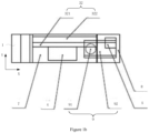
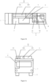
- a mobile radiation inspection apparatus which includes a vehicle body 1, a traveling mechanism 2, a boom assembly 3, a first imaging device 4, and a second imaging device 5.
- the vehicle body 1 is configured to provide support.
- the traveling mechanism 2 is mounted on the vehicle body 1 to drive the vehicle body 1 to travel.
- the mobile radiation inspection apparatus includes a transportation state and an inspection state.
- the boom assembly 3 is also in the transportation state.
- the boom assembly 3 is also in the inspection state.
- the vehicle body 1 is a main body part of the mobile radiation inspection apparatus, and is configured to provide a cab, a carriage, a chassis and the like.
- the traveling mechanism 2 may be implemented in various ways such as wheels and tracks. If the wheels are used, two tires may be mounted at an end of each axle of the vehicle for mounting tires.
- the boom assembly 3 is mounted on the vehicle body 1.
- the boom assembly 3 is configured to switch between the inspection state and the transportation state.
- the boom assembly 3 is retracted and carried by the vehicle body 1. Further, all components of the mobile radiation inspection apparatus are carried and transported by themselves, and there is no need to disassemble some of the components or rely on other tools for transporting to other sites.
- the boom assembly 3 is stretched and matched with a side surface of the vehicle body 1 to jointly form an inspection channel. Power required for stretching the boom assembly 3 comes from the mobile radiation inspection apparatus itself, and no additional driving mechanism is provided to drive the boom assembly 3 to deform.
- Weight of the boom assembly 3 is an important constituent part of total weight of the mobile radiation inspection apparatus. Carrying capacity of the chassis is determined, and if the boom assembly 3 is overweight, number of imaging devices that can be provided on the mobile radiation inspection apparatus is limited. However, if the boom assembly 3 is too light, the carrying capacity thereof is limited, which also affects the number of the imaging devices. Hence, the boom assembly 3 with weak carrying capacity may not be able to carry the imaging devices. For the boom assembly 3 with strong carrying capacity, the bearing capacity of the mobile radiation inspection apparatus is limited because of its heavy weight, and the imaging devices may still be unable to be mounted.
- a material of the boom assembly 3 is optimized, and is selected from lightweight materials with high carrying capacity such as aluminum alloy or titanium alloy.
- each boom of the boom assembly 3 is provided with a structure such as a reinforcing rib in addition to a main beam, to reduce a risk of bending deformation of the boom assembly 3.
- the main beam of the boom assembly 3 may be formed by arranging a plurality of profiles in parallel, and the main beam of this structure also has relatively high bending performance.
- the boom assembly 3 includes a first boom 31, a second boom 32, and a third boom 33. States of the first boom 31, the second boom 32 and the third boom 33 may be switched.
- the first boom 31, the second boom 32, and the third boom 33 are all positioned at the top of the vehicle body 1 and transported with the vehicle body 1.
- the boom assembly 3 is in the inspection state, the first boom 31, the second boom 32 and the third boom 33 are stretched to form an inspection channel P on the side surface of the vehicle body 1. None of the first boom 31, the second boom 32 and the third boom 33 needs to be detached from the vehicle body 1 in either the transportation state or the inspection state.
- the first boom 31, the second boom 32 and the third boom 33 always keep connected to the vehicle body 1. In this setting mode, the boom assembly 3 does not need to be disassembled and assembled repeatedly, and thus transportation to other sites is more convenient.
- the first boom 31 is mounted on the vehicle body 1 in a liftable manner, and the first boom 31 is specifically mounted at the top of the vehicle body 1.
- a lifting drive mechanism is provided on the vehicle body 1.
- the lifting drive mechanism adopts, for example, belt drive and gear drive.
- the drive mechanism drives the first boom 31 to stretch relative to the vehicle body 1, such that the top of the first boom 31 is higher than the top of the vehicle, and the height of the inspection channel formed is relatively high, to meet the inspection requirements of the large-scale and high-load object 10 to be detected.
- the first boom 31 is configured to be telescopic.
- the first boom 31 adopts a plurality of nested segments. When scanning is needed, the segments are stretched one by one.
- the first boom 31 includes a stretched state and a retracted state.
- the first boom 31 is lowered to be completely positioned inside the vehicle body 1 or partially positioned inside the vehicle body 1, to shorten the height of the first boom 31 stretching out of the vehicle body 1, such that the height size of the vehicle meets the requirements of road laws and regulations for vehicles during the transportation of the mobile radiation inspection apparatus to other sites.
- the second boom 32 is mounted on the first boom 31, and they are fixedly connected, for example, by means of fasteners such as bolts.
- the first boom 31 is mounted on a slewing platform 92 which is described hereinafter.
- the slewing platform 92 drives the first boom 31, the second boom 32 and the third boom 33 to rotate synchronously with respect to the vehicle body 1.
- the second boom 32 serves as a top beam of the inspection channel.
- the first imaging device 4 described above is mounted on the second boom 32.
- the first imaging device 4 keeps connected to the second boom 32 regardless of whether the second boom 32 is in the inspection state or the transportation state, and a relative positional relationship between the first imaging device 4 and the second boom 32 remains unchanged.
- the second boom 32 includes a beam 321 and a detection arm 322, which are fixedly connected to achieve effects of reducing the weight and guaranteeing the carrying capacity.
- the detection arm 322 is positioned on a side surface of the beam 321.
- the side surface herein is taken as an example in the inspection state, that is, the detection arm 322 is positioned in a direction of the beam 321 passing through the inspection channel along the object to be detected. Specifically, the relative positions of the detection arm 322 and the beam 321 illustrated in FIG. 2b and FIG. 2c are adopted.
- the first boom 31 When the boom assembly 3 is in the transportation state, the first boom 31 is retracted; and the second boom 32 and the first boom 31 are jointly rotated, under the drive of the slewing platform 92, to a position where the second boom 32 is parallel to the vehicle body 1 and are positioned at the top of the vehicle body 1.
- the boom assembly 3 When the boom assembly 3 is in the inspection state, the first boom 31 stretches out of the top of the vehicle body 1, the second boom 32 and the first boom 31 are rotated together, and the second boom 32 is mostly positioned outside the vehicle body 1.
- the third boom 33 is parallel to the first boom 31, and the third boom 33 and the first boom 31 are arranged at two ends of the second boom 32.
- the first boom 31, the second boom 32 and the third boom 33 are matched with the vehicle body 1 to jointly form the inspection channel.
- the mobile radiation inspection apparatus further includes a first cabin body 7 and a second cabin body 8.
- the first cabin body 7 and the second cabin body 8 may be closed cabin bodies or open cabin bodies. Whether the cabin bodies are closed or not depends on whether scanning rays are required to penetrate through walls of the cabin bodies.
- the cabin bodies may be set to be closed if the rays penetrating through the walls of the cabin bodies does not adversely affect or less adversely affect scanning inspection effects. If the rays penetrating through the walls of the cabin bodies may obviously adversely affect the scanning inspection effects, the cabin bodies need to be set to be open in a path of the rays, such that the rays can complete the scanning inspection operation well.
- the first cabin body 7 is fixedly mounted on the vehicle body 1, for example, by means of bolt connection or the like. In the inspection state and the transportation state, the position of the first cabin body 7 relative to the vehicle body 1 is fixed, and no relative movement occurs between the first cabin body 7 and the vehicle body 1.
- the second cabin body 8 is rotatably mounted at the tail of the vehicle body 1.
- the second cabin body 8 is positioned at the tail of the vehicle body 1.
- the second cabin body 8 is rotated to the side surface of the vehicle body 1, and both the second cabin body 8 and the boom assembly 3 are positioned in the width direction of the vehicle body 1 and are positioned on two sides of the vehicle body 1.
- the vehicle body 1 is provided with a slewing mechanism 9, and the second cabin body 8 is mounted on the slewing mechanism 9, and the second cabin body 8 is driven by the slewing mechanism 9 to rotate, to implement the switching between the transportation state and the inspection state of the second cabin body 8.
- the slewing mechanism 9 includes a slewing support 91 and a slewing platform 92.
- the slewing support 91 is rotatably mounted on the vehicle body 1
- the slewing platform 92 is mounted on the slewing support 91
- the second cabin body 8 is mounted on the slewing platform 92.
- An external force drives the slewing platform 92 and the second cabin body 8 to rotate synchronously.
- the mobile radiation inspection apparatus includes a first imaging device 4 and a second imaging device 5.
- the first imaging device 4 includes a first ray source and a first ray detector both mounted on the boom assembly 3.
- the first ray detector cooperates with the first ray source to detect a ray emitted by the first ray source; and the first ray source is positioned at the top of the inspection channel.
- the first imaging device 4 employs a backscatter principle for imaging, where both the first ray source and the first ray detector of the first imaging device 4 are mounted on a same side of the object to be detected. Referring to FIG. 2c , taking a direction indicated by the inspection state as an example, both the first ray source and the first ray detector are mounted on the top of the boom assembly 3.
- the first imaging device 4 is mounted on the second boom 32, and specifically may be mounted on the beam 321 of the second boom 32.
- the first imaging device 4 is configured to scan from the top of the object to be detected.
- the first imaging device 4 is a backscatter imaging device.
- the first ray source is a backscattered ray source
- the first ray detector is a backscattered electron detector.
- the second imaging device 5 includes a second ray source and a second ray detector both mounted on the vehicle body 1 and/or the boom.
- the second ray detector cooperates with the second ray source to detect the rays emitted by the second ray source.
- the second ray source is positioned on the side surface of the detection channel P.
- One of the second radiation source and the second radiation detector is mounted on the vehicle body 1, and the other one of the second radiation source and the second radiation detector is mounted on the boom assembly 3.
- the second ray source is mounted on the vehicle body 1, and the second ray detector is mounted on the third boom 33 of the boom assembly 3.
- a position of a target 51 of the second imaging device 5 is shown in FIG. 2c .
- the second imaging device 5 is a transmission imaging device
- the second ray source is a transmission ray source
- the second ray detector is a transmission ray detector.
- a dotted line S 1 indicates a ray path of the first imaging device 4.
- a single-dot line S2 indicates a ray path of the second imaging device 5.
- the first ray source and the first ray detector of the first imaging device 4 jointly form a first beam plane M1
- the second ray source and the second ray detector of the second imaging device 5 jointly form a second beam plane M2, where the first beam plane M1 is parallel to the second beam plane M2.
- the first imaging device 4 and the second imaging device 5 are independent of each other and are separately controlled. Parameters such as start-stop, dose control and working time of the first imaging device 4 and the second imaging device 5 are separately controlled and do not affect each other.
- the second ray source is arranged in the second cabin body 8, and the second ray detector is arranged on the third boom 33 of the boom assembly 3.
- the second ray source is arranged on the third boom 33 of the boom assembly 3, and the second ray detector is arranged in the second cabin body 8.
- the second ray source is mounted in the second cabin body 8, and the second ray detector is mounted on the third boom 33.
- a total weight of the second cabin body 8 and the second ray source is configured to maintain balance with a total weight of the boom assembly 3, the first imaging device 4 and the second ray detector such that the mobile radiation inspection apparatus remains stable in the width direction of the vehicle body 1.
- At least a side of the second cabin body 8 is configured to be open such that when the boom assembly is in the inspection state, the second ray source positioned in the second cabin body 8 is prevented from being blocked and directly radiates to the object 10 to be detected.
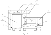
- FIGS. 3a to 4c some other embodiments are described below. These embodiments differ from the above embodiments in that in these embodiments the mobile radiation inspection apparatus is further provided with a third imaging device 6 in addition to the first imaging device 4 and the second imaging device 5 described above.
- the mobile radiation inspection apparatus further comprises a third imaging device 6, which includes a third ray source and a third ray detector both mounted on the boom assembly 3 or the vehicle body 1.
- the third ray detector cooperates with the third ray source to detect a ray emitted by the third ray source; and the third ray source is positioned on the side surface of the detection channel P.
- the third imaging device 6 is a backscatter imaging device, the third ray source is a backscatter ray source, and the third ray detector is a backscattered electron detector.
- the first ray source and the first ray detector of the first imaging device 4 jointly form a first beam plane M1
- the second ray source and the second ray detector of the second imaging device 5 jointly form a second beam plane M2
- the third ray source and the third ray detector of the third imaging device 6 jointly form a third beam plane M3, where the first beam plane M1, the second beam plane M2 and third beam plane M3 are parallel to each other.
- the third imaging device 6 is arranged in the first cabin body 7.
- at least one side of the first cabin body 7 is configured to be open such that when the boom assembly is in the inspection state, the third ray source positioned in the first cabin body 7 is prevented from being blocked and directly radiates to the object 10 to be detected.
- orientation or position relations denoted by the terms “center”, “longitudinal”, “transverse”, “front”, “rear”, “left”, “right”, “vertical”, “horizontal”, “top', “bottom”, “inner”, “outer” and the like are orientation or position relations illustrated based on the drawings, are merely for the convenience of describing the present disclosure and simplifying description, instead of indicating or implying the denoted devices or elements must have specific orientations or be constructed and operated in specific orientations, and thus the terms cannot be construed as limiting the protection scope of the present disclosure.
Landscapes
- Physics & Mathematics (AREA)
- Life Sciences & Earth Sciences (AREA)
- General Physics & Mathematics (AREA)
- Geophysics (AREA)
- General Life Sciences & Earth Sciences (AREA)
- High Energy & Nuclear Physics (AREA)
- General Health & Medical Sciences (AREA)
- Biochemistry (AREA)
- Immunology (AREA)
- Pathology (AREA)
- Analytical Chemistry (AREA)
- Chemical & Material Sciences (AREA)
- Health & Medical Sciences (AREA)
- Analysing Materials By The Use Of Radiation (AREA)
Applications Claiming Priority (1)
| Application Number | Priority Date | Filing Date | Title |
|---|---|---|---|
| CN202111668874.0A CN114137622A (zh) | 2021-12-30 | 2021-12-30 | 移动式辐射检查设备以及移动式辐射检查系统 |
Publications (1)
| Publication Number | Publication Date |
|---|---|
| EP4206751A1 true EP4206751A1 (de) | 2023-07-05 |
Family
ID=80384036
Family Applications (1)
| Application Number | Title | Priority Date | Filing Date |
|---|---|---|---|
| EP22217075.5A Pending EP4206751A1 (de) | 2021-12-30 | 2022-12-29 | Mobile strahlungsinspektionsvorrichtung und mobiles strahlungsinspektionssystem |
Country Status (4)
| Country | Link |
|---|---|
| US (1) | US20240411045A1 (de) |
| EP (1) | EP4206751A1 (de) |
| CN (1) | CN114137622A (de) |
| WO (1) | WO2023125084A1 (de) |
Families Citing this family (6)
| Publication number | Priority date | Publication date | Assignee | Title |
|---|---|---|---|---|
| CN114137622A (zh) * | 2021-12-30 | 2022-03-04 | 同方威视科技(北京)有限公司 | 移动式辐射检查设备以及移动式辐射检查系统 |
| CN114779359A (zh) * | 2022-04-12 | 2022-07-22 | 北京华力兴科技发展有限责任公司 | 一种挂车式车载检查系统及检查方法 |
| CN115166807A (zh) * | 2022-05-27 | 2022-10-11 | 中国船舶重工集团公司第七一九研究所 | 一种用于人员表面污染检测仪快速展开的机械臂 |
| CN116297559B (zh) * | 2022-12-28 | 2026-04-10 | 同方威视技术股份有限公司 | 安全检查系统 |
| CN116184516A (zh) * | 2022-12-30 | 2023-05-30 | 同方威视技术股份有限公司 | 检查系统及其安装方法 |
| CN119200014A (zh) * | 2024-10-12 | 2024-12-27 | 同方威视技术股份有限公司 | 辐射扫描检查设备 |
Citations (3)
| Publication number | Priority date | Publication date | Assignee | Title |
|---|---|---|---|---|
| US8824632B2 (en) * | 2009-07-29 | 2014-09-02 | American Science And Engineering, Inc. | Backscatter X-ray inspection van with top-down imaging |
| US20160025890A1 (en) * | 2012-02-03 | 2016-01-28 | Rapiscan Systems, Inc. | Combined Scatter and Transmission Multi-View Imaging System |
| WO2016034101A2 (zh) * | 2014-09-02 | 2016-03-10 | 清华大学 | 车载式检查系统 |
Family Cites Families (23)
| Publication number | Priority date | Publication date | Assignee | Title |
|---|---|---|---|---|
| US5764683B1 (en) * | 1996-02-12 | 2000-11-21 | American Science & Eng Inc | Mobile x-ray inspection system for large objects |
| US9958569B2 (en) * | 2002-07-23 | 2018-05-01 | Rapiscan Systems, Inc. | Mobile imaging system and method for detection of contraband |
| US8275091B2 (en) * | 2002-07-23 | 2012-09-25 | Rapiscan Systems, Inc. | Compact mobile cargo scanning system |
| US7322745B2 (en) * | 2002-07-23 | 2008-01-29 | Rapiscan Security Products, Inc. | Single boom cargo scanning system |
| CN1181336C (zh) * | 2002-10-16 | 2004-12-22 | 清华大学 | 一种车载移动式集装箱检查系统 |
| CN2572400Y (zh) * | 2002-10-16 | 2003-09-10 | 清华大学 | 一种车载移动式集装箱检查系统 |
| US20090257555A1 (en) * | 2002-11-06 | 2009-10-15 | American Science And Engineering, Inc. | X-Ray Inspection Trailer |
| CN1627061A (zh) * | 2003-12-10 | 2005-06-15 | 清华同方威视技术股份有限公司 | 一种组合移动式低靶点集装箱检查系统 |
| CN200996943Y (zh) * | 2006-10-09 | 2007-12-26 | 同方威视技术股份有限公司 | 一种货物检查设备 |
| CN102012527A (zh) * | 2010-11-25 | 2011-04-13 | 上海英迈吉东影图像设备有限公司 | 移动式x射线检查车及其检查方法 |
| CN102854539B (zh) * | 2011-06-29 | 2016-05-04 | 上海英迈吉东影图像设备有限公司 | 一种基于背散射成像的外挂式移动检查系统 |
| CN103529061B (zh) * | 2012-07-04 | 2016-03-09 | 同方威视技术股份有限公司 | 车载式辐射检查系统 |
| CN204086172U (zh) * | 2014-09-02 | 2015-01-07 | 清华大学 | 车载式检查系统 |
| WO2017208380A1 (ja) * | 2016-06-01 | 2017-12-07 | 株式会社島津製作所 | 移動型x線撮影装置 |
| CN106290420B (zh) * | 2016-08-31 | 2019-11-12 | 同方威视技术股份有限公司 | 可移动式物品检查系统及检查方法 |
| CN106772650A (zh) * | 2016-12-26 | 2017-05-31 | 同方威视技术股份有限公司 | 移动式排爆透射成像装置 |
| CN206573504U (zh) * | 2017-02-17 | 2017-10-20 | 清华大学 | 多视角背散射检查系统 |
| CN107861165A (zh) * | 2017-10-17 | 2018-03-30 | 青岛新前湾集装箱码头有限责任公司 | 移动式物品检查系统 |
| CN107991323A (zh) * | 2017-11-21 | 2018-05-04 | 同方威视技术股份有限公司 | 车载式辐射检查系统 |
| CN108732192A (zh) * | 2018-05-09 | 2018-11-02 | 清华大学 | 安全检查系统 |
| CN212872940U (zh) * | 2020-07-22 | 2021-04-02 | 中国原子能科学研究院 | 一种车载式集装箱或货车透视扫描快速安检装置 |
| CN114137622A (zh) * | 2021-12-30 | 2022-03-04 | 同方威视科技(北京)有限公司 | 移动式辐射检查设备以及移动式辐射检查系统 |
| CN217060528U (zh) * | 2021-12-30 | 2022-07-26 | 同方威视科技(北京)有限公司 | 移动式辐射检查设备以及移动式辐射检查系统 |
-
2021
- 2021-12-30 CN CN202111668874.0A patent/CN114137622A/zh active Pending
-
2022
- 2022-12-16 US US18/716,943 patent/US20240411045A1/en active Pending
- 2022-12-16 WO PCT/CN2022/139764 patent/WO2023125084A1/zh not_active Ceased
- 2022-12-29 EP EP22217075.5A patent/EP4206751A1/de active Pending
Patent Citations (3)
| Publication number | Priority date | Publication date | Assignee | Title |
|---|---|---|---|---|
| US8824632B2 (en) * | 2009-07-29 | 2014-09-02 | American Science And Engineering, Inc. | Backscatter X-ray inspection van with top-down imaging |
| US20160025890A1 (en) * | 2012-02-03 | 2016-01-28 | Rapiscan Systems, Inc. | Combined Scatter and Transmission Multi-View Imaging System |
| WO2016034101A2 (zh) * | 2014-09-02 | 2016-03-10 | 清华大学 | 车载式检查系统 |
Also Published As
| Publication number | Publication date |
|---|---|
| WO2023125084A1 (zh) | 2023-07-06 |
| CN114137622A (zh) | 2022-03-04 |
| US20240411045A1 (en) | 2024-12-12 |
Similar Documents
| Publication | Publication Date | Title |
|---|---|---|
| EP4206751A1 (de) | Mobile strahlungsinspektionsvorrichtung und mobiles strahlungsinspektionssystem | |
| CN112946770B (zh) | 扫描检查设备以及扫描检查系统 | |
| RU2402013C1 (ru) | Устройство детектирования | |
| US10156528B2 (en) | Movable divided inspection system and method | |
| EP3346300B1 (de) | Bewegliches artikeluntersuchungssystem | |
| CN109444971B (zh) | 一种物品检测装置 | |
| KR20040034481A (ko) | 차량으로 운반되는 이동 컨테이너 점검 장치 | |
| US20080089469A1 (en) | Mobile vehicle inspection system | |
| US11747510B2 (en) | Security inspection device | |
| GB2594201A (en) | Security inspection device and site transfer method thereof | |
| CN109633767B (zh) | 检查装置及基于该检查装置的转场方法 | |
| CN109490977B (zh) | 检查设备 | |
| WO2020140981A1 (zh) | 辐射检查设备 | |
| WO2022143164A1 (zh) | 辐射检查系统 | |
| CA3073497A1 (en) | Dump truck | |
| CN203416494U (zh) | 驻波电子直线加速器及集装箱/车辆检查系统 | |
| CN217060528U (zh) | 移动式辐射检查设备以及移动式辐射检查系统 | |
| CN109597138B (zh) | 一种物品检测装置 | |
| CN109521483B (zh) | 检查设备 | |
| CN209542864U (zh) | 辐射检查设备 | |
| EP4206750A1 (de) | Mobile inspektionsvorrichtung und mobiles inspektionsverfahren | |
| CN221317710U (zh) | 运载设备 | |
| RU2856787C2 (ru) | Мобильный аппарат для радиационного досмотра и мобильная система радиационного досмотра | |
| PL241870B1 (pl) | Układ i sposób do kontroli pojazdu | |
| US20250140431A1 (en) | Ray protection device and radiation inspection system |
Legal Events
| Date | Code | Title | Description |
|---|---|---|---|
| PUAI | Public reference made under article 153(3) epc to a published international application that has entered the european phase |
Free format text: ORIGINAL CODE: 0009012 |
|
| STAA | Information on the status of an ep patent application or granted ep patent |
Free format text: STATUS: REQUEST FOR EXAMINATION WAS MADE |
|
| 17P | Request for examination filed |
Effective date: 20221229 |
|
| AK | Designated contracting states |
Kind code of ref document: A1 Designated state(s): AL AT BE BG CH CY CZ DE DK EE ES FI FR GB GR HR HU IE IS IT LI LT LU LV MC ME MK MT NL NO PL PT RO RS SE SI SK SM TR |
|
| STAA | Information on the status of an ep patent application or granted ep patent |
Free format text: STATUS: EXAMINATION IS IN PROGRESS |
|
| 17Q | First examination report despatched |
Effective date: 20250924 |