EP4204604B1 - Elektrode mit verbesserter abschalttoleranz - Google Patents
Elektrode mit verbesserter abschalttoleranz Download PDFInfo
- Publication number
- EP4204604B1 EP4204604B1 EP21763107.6A EP21763107A EP4204604B1 EP 4204604 B1 EP4204604 B1 EP 4204604B1 EP 21763107 A EP21763107 A EP 21763107A EP 4204604 B1 EP4204604 B1 EP 4204604B1
- Authority
- EP
- European Patent Office
- Prior art keywords
- compound
- nickel
- catalytic layer
- electrode
- active composition
- Prior art date
- Legal status (The legal status is an assumption and is not a legal conclusion. Google has not performed a legal analysis and makes no representation as to the accuracy of the status listed.)
- Active
Links
Images


Classifications
-
- C—CHEMISTRY; METALLURGY
- C23—COATING METALLIC MATERIAL; COATING MATERIAL WITH METALLIC MATERIAL; CHEMICAL SURFACE TREATMENT; DIFFUSION TREATMENT OF METALLIC MATERIAL; COATING BY VACUUM EVAPORATION, BY SPUTTERING, BY ION IMPLANTATION OR BY CHEMICAL VAPOUR DEPOSITION, IN GENERAL; INHIBITING CORROSION OF METALLIC MATERIAL OR INCRUSTATION IN GENERAL
- C23C—COATING METALLIC MATERIAL; COATING MATERIAL WITH METALLIC MATERIAL; SURFACE TREATMENT OF METALLIC MATERIAL BY DIFFUSION INTO THE SURFACE, BY CHEMICAL CONVERSION OR SUBSTITUTION; COATING BY VACUUM EVAPORATION, BY SPUTTERING, BY ION IMPLANTATION OR BY CHEMICAL VAPOUR DEPOSITION, IN GENERAL
- C23C4/00—Coating by spraying the coating material in the molten state, e.g. by flame, plasma or electric discharge
- C23C4/04—Coating by spraying the coating material in the molten state, e.g. by flame, plasma or electric discharge characterised by the coating material
- C23C4/06—Metallic material
- C23C4/08—Metallic material containing only metal elements
-
- C—CHEMISTRY; METALLURGY
- C23—COATING METALLIC MATERIAL; COATING MATERIAL WITH METALLIC MATERIAL; CHEMICAL SURFACE TREATMENT; DIFFUSION TREATMENT OF METALLIC MATERIAL; COATING BY VACUUM EVAPORATION, BY SPUTTERING, BY ION IMPLANTATION OR BY CHEMICAL VAPOUR DEPOSITION, IN GENERAL; INHIBITING CORROSION OF METALLIC MATERIAL OR INCRUSTATION IN GENERAL
- C23C—COATING METALLIC MATERIAL; COATING MATERIAL WITH METALLIC MATERIAL; SURFACE TREATMENT OF METALLIC MATERIAL BY DIFFUSION INTO THE SURFACE, BY CHEMICAL CONVERSION OR SUBSTITUTION; COATING BY VACUUM EVAPORATION, BY SPUTTERING, BY ION IMPLANTATION OR BY CHEMICAL VAPOUR DEPOSITION, IN GENERAL
- C23C4/00—Coating by spraying the coating material in the molten state, e.g. by flame, plasma or electric discharge
- C23C4/18—After-treatment
-
- C—CHEMISTRY; METALLURGY
- C25—ELECTROLYTIC OR ELECTROPHORETIC PROCESSES; APPARATUS THEREFOR
- C25B—ELECTROLYTIC OR ELECTROPHORETIC PROCESSES FOR THE PRODUCTION OF COMPOUNDS OR NON-METALS; APPARATUS THEREFOR
- C25B1/00—Electrolytic production of inorganic compounds or non-metals
- C25B1/01—Products
- C25B1/02—Hydrogen or oxygen
- C25B1/04—Hydrogen or oxygen by electrolysis of water
-
- C—CHEMISTRY; METALLURGY
- C25—ELECTROLYTIC OR ELECTROPHORETIC PROCESSES; APPARATUS THEREFOR
- C25B—ELECTROLYTIC OR ELECTROPHORETIC PROCESSES FOR THE PRODUCTION OF COMPOUNDS OR NON-METALS; APPARATUS THEREFOR
- C25B11/00—Electrodes; Manufacture thereof not otherwise provided for
- C25B11/02—Electrodes; Manufacture thereof not otherwise provided for characterised by shape or form
- C25B11/03—Electrodes; Manufacture thereof not otherwise provided for characterised by shape or form perforated or foraminous
- C25B11/031—Porous electrodes
-
- C—CHEMISTRY; METALLURGY
- C25—ELECTROLYTIC OR ELECTROPHORETIC PROCESSES; APPARATUS THEREFOR
- C25B—ELECTROLYTIC OR ELECTROPHORETIC PROCESSES FOR THE PRODUCTION OF COMPOUNDS OR NON-METALS; APPARATUS THEREFOR
- C25B11/00—Electrodes; Manufacture thereof not otherwise provided for
- C25B11/04—Electrodes; Manufacture thereof not otherwise provided for characterised by the material
- C25B11/051—Electrodes formed of electrocatalysts on a substrate or carrier
- C25B11/052—Electrodes comprising one or more electrocatalytic coatings on a substrate
- C25B11/053—Electrodes comprising one or more electrocatalytic coatings on a substrate characterised by multilayer electrocatalytic coatings
-
- C—CHEMISTRY; METALLURGY
- C25—ELECTROLYTIC OR ELECTROPHORETIC PROCESSES; APPARATUS THEREFOR
- C25B—ELECTROLYTIC OR ELECTROPHORETIC PROCESSES FOR THE PRODUCTION OF COMPOUNDS OR NON-METALS; APPARATUS THEREFOR
- C25B11/00—Electrodes; Manufacture thereof not otherwise provided for
- C25B11/04—Electrodes; Manufacture thereof not otherwise provided for characterised by the material
- C25B11/051—Electrodes formed of electrocatalysts on a substrate or carrier
- C25B11/055—Electrodes formed of electrocatalysts on a substrate or carrier characterised by the substrate or carrier material
- C25B11/056—Electrodes formed of electrocatalysts on a substrate or carrier characterised by the substrate or carrier material consisting of textile or non-woven fabric
-
- C—CHEMISTRY; METALLURGY
- C25—ELECTROLYTIC OR ELECTROPHORETIC PROCESSES; APPARATUS THEREFOR
- C25B—ELECTROLYTIC OR ELECTROPHORETIC PROCESSES FOR THE PRODUCTION OF COMPOUNDS OR NON-METALS; APPARATUS THEREFOR
- C25B11/00—Electrodes; Manufacture thereof not otherwise provided for
- C25B11/04—Electrodes; Manufacture thereof not otherwise provided for characterised by the material
- C25B11/051—Electrodes formed of electrocatalysts on a substrate or carrier
- C25B11/055—Electrodes formed of electrocatalysts on a substrate or carrier characterised by the substrate or carrier material
- C25B11/057—Electrodes formed of electrocatalysts on a substrate or carrier characterised by the substrate or carrier material consisting of a single element or compound
- C25B11/061—Metal or alloy
-
- C—CHEMISTRY; METALLURGY
- C25—ELECTROLYTIC OR ELECTROPHORETIC PROCESSES; APPARATUS THEREFOR
- C25B—ELECTROLYTIC OR ELECTROPHORETIC PROCESSES FOR THE PRODUCTION OF COMPOUNDS OR NON-METALS; APPARATUS THEREFOR
- C25B11/00—Electrodes; Manufacture thereof not otherwise provided for
- C25B11/04—Electrodes; Manufacture thereof not otherwise provided for characterised by the material
- C25B11/051—Electrodes formed of electrocatalysts on a substrate or carrier
- C25B11/073—Electrodes formed of electrocatalysts on a substrate or carrier characterised by the electrocatalyst material
- C25B11/075—Electrodes formed of electrocatalysts on a substrate or carrier characterised by the electrocatalyst material consisting of a single catalytic element or catalytic compound
- C25B11/077—Electrodes formed of electrocatalysts on a substrate or carrier characterised by the electrocatalyst material consisting of a single catalytic element or catalytic compound the compound being a non-noble metal oxide
-
- C—CHEMISTRY; METALLURGY
- C25—ELECTROLYTIC OR ELECTROPHORETIC PROCESSES; APPARATUS THEREFOR
- C25B—ELECTROLYTIC OR ELECTROPHORETIC PROCESSES FOR THE PRODUCTION OF COMPOUNDS OR NON-METALS; APPARATUS THEREFOR
- C25B11/00—Electrodes; Manufacture thereof not otherwise provided for
- C25B11/04—Electrodes; Manufacture thereof not otherwise provided for characterised by the material
- C25B11/051—Electrodes formed of electrocatalysts on a substrate or carrier
- C25B11/073—Electrodes formed of electrocatalysts on a substrate or carrier characterised by the electrocatalyst material
- C25B11/091—Electrodes formed of electrocatalysts on a substrate or carrier characterised by the electrocatalyst material consisting of at least one catalytic element and at least one catalytic compound; consisting of two or more catalytic elements or catalytic compounds
-
- C—CHEMISTRY; METALLURGY
- C25—ELECTROLYTIC OR ELECTROPHORETIC PROCESSES; APPARATUS THEREFOR
- C25D—PROCESSES FOR THE ELECTROLYTIC OR ELECTROPHORETIC PRODUCTION OF COATINGS; ELECTROFORMING; APPARATUS THEREFOR
- C25D3/00—Electroplating: Baths therefor
- C25D3/02—Electroplating: Baths therefor from solutions
- C25D3/12—Electroplating: Baths therefor from solutions of nickel or cobalt
-
- C—CHEMISTRY; METALLURGY
- C25—ELECTROLYTIC OR ELECTROPHORETIC PROCESSES; APPARATUS THEREFOR
- C25D—PROCESSES FOR THE ELECTROLYTIC OR ELECTROPHORETIC PRODUCTION OF COATINGS; ELECTROFORMING; APPARATUS THEREFOR
- C25D7/00—Electroplating characterised by the article coated
-
- C—CHEMISTRY; METALLURGY
- C25—ELECTROLYTIC OR ELECTROPHORETIC PROCESSES; APPARATUS THEREFOR
- C25D—PROCESSES FOR THE ELECTROLYTIC OR ELECTROPHORETIC PRODUCTION OF COATINGS; ELECTROFORMING; APPARATUS THEREFOR
- C25D9/00—Electrolytic coating other than with metals
- C25D9/04—Electrolytic coating other than with metals with inorganic materials
-
- C—CHEMISTRY; METALLURGY
- C25—ELECTROLYTIC OR ELECTROPHORETIC PROCESSES; APPARATUS THEREFOR
- C25B—ELECTROLYTIC OR ELECTROPHORETIC PROCESSES FOR THE PRODUCTION OF COMPOUNDS OR NON-METALS; APPARATUS THEREFOR
- C25B11/00—Electrodes; Manufacture thereof not otherwise provided for
- C25B11/04—Electrodes; Manufacture thereof not otherwise provided for characterised by the material
- C25B11/051—Electrodes formed of electrocatalysts on a substrate or carrier
- C25B11/073—Electrodes formed of electrocatalysts on a substrate or carrier characterised by the electrocatalyst material
- C25B11/091—Electrodes formed of electrocatalysts on a substrate or carrier characterised by the electrocatalyst material consisting of at least one catalytic element and at least one catalytic compound; consisting of two or more catalytic elements or catalytic compounds
- C25B11/093—Electrodes formed of electrocatalysts on a substrate or carrier characterised by the electrocatalyst material consisting of at least one catalytic element and at least one catalytic compound; consisting of two or more catalytic elements or catalytic compounds at least one noble metal or noble metal oxide and at least one non-noble metal oxide
-
- Y—GENERAL TAGGING OF NEW TECHNOLOGICAL DEVELOPMENTS; GENERAL TAGGING OF CROSS-SECTIONAL TECHNOLOGIES SPANNING OVER SEVERAL SECTIONS OF THE IPC; TECHNICAL SUBJECTS COVERED BY FORMER USPC CROSS-REFERENCE ART COLLECTIONS [XRACs] AND DIGESTS
- Y02—TECHNOLOGIES OR APPLICATIONS FOR MITIGATION OR ADAPTATION AGAINST CLIMATE CHANGE
- Y02E—REDUCTION OF GREENHOUSE GAS [GHG] EMISSIONS, RELATED TO ENERGY GENERATION, TRANSMISSION OR DISTRIBUTION
- Y02E60/00—Enabling technologies; Technologies with a potential or indirect contribution to GHG emissions mitigation
- Y02E60/30—Hydrogen technology
- Y02E60/36—Hydrogen production from non-carbon containing sources, e.g. by water electrolysis
-
- Y—GENERAL TAGGING OF NEW TECHNOLOGICAL DEVELOPMENTS; GENERAL TAGGING OF CROSS-SECTIONAL TECHNOLOGIES SPANNING OVER SEVERAL SECTIONS OF THE IPC; TECHNICAL SUBJECTS COVERED BY FORMER USPC CROSS-REFERENCE ART COLLECTIONS [XRACs] AND DIGESTS
- Y02—TECHNOLOGIES OR APPLICATIONS FOR MITIGATION OR ADAPTATION AGAINST CLIMATE CHANGE
- Y02P—CLIMATE CHANGE MITIGATION TECHNOLOGIES IN THE PRODUCTION OR PROCESSING OF GOODS
- Y02P20/00—Technologies relating to chemical industry
- Y02P20/10—Process efficiency
- Y02P20/133—Renewable energy sources, e.g. sunlight
Definitions
- the present disclosure relates to electrodes and more particularly to electrodes for use in electrolysis processes.
- Hydrogen is emerging as an important part of the clean energy paradigm. It can be used as a high efficiency, low polluting fuel, as well as an energy carrier for moving, storing and delivering energy from renewable energy sources. Moreover, hydrogen can be produced from water, which is an abundant and relatively inexpensive feedstock.
- a number of different processes can be used for producing hydrogen from water. These processes include water electrolysis, photo-electrolysis, photo-biological production and high temperature decomposition. Of these processes, water electrolysis is the most practical way to produce hydrogen using renewable energy sources, such as power from wind turbines and/or photovoltaic solar panels.
- alkaline electrolysis There are several types of water electrolysis processes that are used for hydrogen generation, namely alkaline electrolysis, proton exchange membrane (PEM) electrolysis, and solid oxide electrolytic cell (SOEC) electrolysis.
- PEM proton exchange membrane
- SOEC solid oxide electrolytic cell
- a DC electrical power source is connected to two electrodes, which are placed in water. Theoretically, a potential difference between the electrodes of 1.23 volts will split water into hydrogen and oxygen. Hydrogen is produced at the cathode, while oxygen is produced at the anode. More specifically, there is a hydrogen evolution reaction ("HER") at the cathode and an oxygen evolution reaction ("OER”) at the anode.
- HER hydrogen evolution reaction
- OER oxygen evolution reaction
- the HER is a reduction reaction in which electrons (e - ) from the cathode are given to hydrogen cations to form hydrogen gas, while the OER is an oxidation reaction in which electrons are given to the anode and oxygen is generated.
- the water contains an alkaline electrolyte, such as potassium hydroxide (KOH) or sodium hydroxide (NaOH), and the electrodes are separated by a diaphragm.
- an alkaline electrolyte such as potassium hydroxide (KOH) or sodium hydroxide (NaOH)
- KOH potassium hydroxide
- NaOH sodium hydroxide
- PEM electrolysis the water is deionized, and the electrodes are separated by a solid polymer electrolyte that permits protons from the anode to pass to the cathode, while insulating the electrodes electrically.
- EP 3296431 A1 describes an oxidized nickel foam electrode having a coating layer comprising crystalline nanoparticles which include nickel, nickel oxide and ion oxide.
- WO 2019/172160 A1 describes an alkaline water electrolysis anode comprising a conductive substrate having an intermediate layer made of nickel oxide and a catalyst layer.
- EP 3064614 A1 describes an anode for alkaline water electrolysis having a nickel substrate and a lithium-containing nickel oxide catalytic layer formed on the substrate.
- EP 3375906 A1 describes an anode for electrochemical reactions which includes a nickel substrate and a nickel oxide layer on the conductive substrate and an oxidation catalyst layer disposed on the oxide layer.
- an electrode for use in an alkaline electrolysis process.
- the electrode includes a metal substrate and a catalytic layer disposed on the metal substrate.
- the catalytic layer includes nickel and nickel oxide and has a porosity less than about 1 m 2 /g measured by BET.
- An active composition is disposed both on and within the catalytic layer.
- the active composition includes one or more metal compounds selected from the group consisting of a cobalt compound, an iridium compound, a rhodium compound, an iron compound, a platinum compound, a lithium compound and a manganese compound.
- an alkaline water electrolysis unit that includes the electrode, which functions as an anode.
- the unit also includes a cathode and an electrolyte solution that is substantially free of chlorine.
- a method of forming an electrode is also disclosed herein.
- a metal substrate is provided and a catalytic layer is formed on the metal substrate.
- the catalytic layer includes nickel and nickel oxide formed by thermal spraying, cold spraying or other surface finishing process such as laser cladding and electroplating, and has a porosity less than about 1 m 2 /g (BET).
- An active composition is applied to the catalytic layer and is thermally decomposed.
- the active composition includes one or more metal compounds selected from the group consisting of a cobalt compound, an iridium compound, a rhodium compound, an iron compound, a platinum compound, a lithium compound and a manganese compound.
- the present disclosure is directed to an electrode 10 constructed for use in an electrolysis process.
- the electrode 10 is especially suited for use in an alkaline electrolysis process and, more particularly, as an anode in such a process.
- a unit 12 that may be used for performing alkaline water electrolysis is shown in Fig. 1 .
- the unit 12 may include the electrode 10, functioning as an anode, and a cathode 14.
- the electrode (anode) 10 and the cathode 14 are separated by a diaphragm 16 and are disposed in a vessel 18 containing an electrolyte solution.
- the electrolyte solution used in the electrolysis process preferably does not include chlorine or other halides.
- the electrolyte solution may comprise water and potassium hydroxide (KOH) or water and sodium hydroxide (NaOH).
- the diaphragm 16 is composed of a microporous material with an average pore size of less than 1 ⁇ m, which allows ions to move between the electrode (anode) 10 and the cathode 14, but is impermeable to gas, thereby preventing the intermixing of generated hydrogen and oxygen gases.
- the diaphragm 16 may be composed of a porous polymer, such as polytetrafluoroethylene (PTFE), or a composite material comprising zirconium dioxide (ZrO 2 ) and polysulfone, which at the time of writing is commercially sold under the trademark Zirfon ® .
- the cathode 14 is composed of conductive metal, which may be nickel, low carbon steel, or stainless steel.
- the cathode 14 may have a structure as described below for the electrode 10 and may be coated with nickel or a nickel-iron alloy.
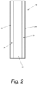
- the electrode 10 includes a substrate 22 upon which a catalytic layer 24 is disposed.
- the catalytic layer 24 has pores formed therein, but is only moderately porous.
- An active composition 26 is disposed in and/or on the catalytic layer 24.
- the active composition 26 may form a layer and/or its constituent components may be interspersed into the pores of the catalytic layer 24.
- the active composition 26 does not form a layer and its constituent parts are distributed throughout the porosity of the catalytic layer 24.
- the active composition 26 forms a layer on the catalytic layer 24 and its constituent parts are also distributed throughout the porosity of the catalytic layer 24.
- the catalytic layer 24 may be disposed over all of the outer surfaces of the substrate 22 and, similarly, the active composition 26 may be disposed in and/or on all of the catalytic layer 24.
- the electrode 10 is shown as having a rectangular configuration, with opposing major surfaces being covered with the catalytic layer 24 and the active composition 26. While not shown, end surfaces of the electrode 10 may also be covered with the catalytic layer 24 and the active composition 26.
- the catalytic layer 24 and the active composition 26 are applied to the substrate 22 so as to be substantially uniform in thickness and composition over the exterior of the substrate 22. Preferably, deiviations in thickness are mostly within a +/- 5 ⁇ m range.
- the substrate 22 may be punched plate, woven wire, wire mesh, metal sponge, expanded metal, perforated or unperforated metal sheet, flat or corrugated lattice work, spaced apart rods or strips, or other structural forms.
- the wire mesh has been found to work particularly well in the execution of the invention.
- the thickness of the substrate 22 is preferably from about 0.15 mm to about 3.0 mm and more preferably from about 0.6 mm to about 2.0 mm.
- the substrate 22 has openings to reduce current density.
- the substrate 22 is composed of a conductive metal, such as iron, iron alloy, nickel, nickel alloy or stainless steel. Iron alloys that may be used include iron-nickel alloys, iron-chromium alloys and iron-nickel-chromium alloys. Nickel alloys that may be used include nickel-copper alloys and nickel chromium alloys.
- the substrate 22 is comprised of nickel, a nickel alloy or an iron alloy.
- a nickel plain weave wire mesh has been found especially suitable for use as the substrate 22.
- the catalytic layer 24 is formed from a metal using a suitable thermal spraying process, such as flame spraying, wire-arc spraying, plasma spraying, high velocity oxyfuel (HVOF) spraying, high velocity air-fuel (HVAF) spraying, detonation gun and combustion wire spraying. Wire-arc spraying and plasma spraying have been observed to work particularly well in the execution of the invention.
- the catalytic layer 24 may alternatively be formed from a metal using cold spraying or another type of surface finishing process, such as laser cladding and electroplating.
- the metal from which the catalytic layer 24 is formed may be nickel or a nickel alloy and/or nickel oxide (NiO).
- nickel is preferred.
- nickel is deposited on the substrate 22 using nickel powder in an atmospheric plasma spraying (APS) process, a cold gas spraying process or a wire-arc spraying process. More preferably, nickel is deposited on the substrate 22 using nickel powder in an APS process.
- the nickel powder that is used to form the catalytic layer 24 has a mean particle size of from about 10 ⁇ m to about 150 ⁇ m, more preferably from about 45 ⁇ m to about 90 ⁇ m.
- the substrate 22 is treated to remove contaminants and condition its surface for receipt of the metal powder.
- the treatment may include removing oil and grease through a degreasing process using a solvent.
- a grit blasting process is preferably performed on the substrate 22 after any degreasing process has been performed.
- abrasive media such as chilled iron or aluminum oxide, is pressurized with compressed air and directed against the surfaces of the substrate 22.
- the grit blasting further removes any contaminants and roughens the surfaces to form pits and crevices that promote mechanical bonding of the metal powder that is sprayed on the surfaces. Debris from the grit blasting may be removed by vacuum cleaning, brushing and/or air blowing.
- An APS process may be performed with a plasma torch in which a strong electric arc is generated between a positively charged pole (anode) and a negatively charged pole (cathode).
- the arc ionizes flowing process gas (such as a mixture of argon, hydrogen, nitrogen and helium) into a plasma state to form a plasma jet, which may have a temperature in range of from about 10,000°C to about 30,000°C.
- process gas such as a mixture of argon, hydrogen, nitrogen and helium
- the anode is circular and helps form a nozzle through which the plasma jet is ejected.
- the anode may be composed of copper, while the cathode may be composed of thoriated tungsten.
- Metal e.g.
- nickel powder is fluidized in a carrier gas (which may include hydrogen) and fed into the plasma jet, melting the powder particles and propelling them at high speeds (such as between 300 to 550 m/s) onto the substrate 22.
- a carrier gas which may include hydrogen
- some of the molten metal particles are oxidized to form oxides, such as nickel oxide (NiO).
- the catalytic layer 24 includes both nickel and nickel oxide.
- the molten metal particles sprayed from the plasma torch impact the substrate 22, where they flatten into "splats", which shrink and solidify to form stacked lamellae with micro-features, such as pores. As the splats shrink and solidify, they mechanically bond to the substrate 22 through mechanical hooking. As such, the adhesion of the sprayed metal particles is primarily due to mechanical bonding.
- metal e.g. nickel
- carrier gas which is preheated to a temperature of up to 1,000°C and may be comprised of nitrogen, helium or air.
- the stream of carrier gas and metal particles is passed through a converging-diverging DeLaval nozzle, where the stream is cooled and accelerated to a supersonic velocity of over 1,000 m/s.
- the supersonic stream of metal particles and carrier gas is directed onto the substrate 22, where the metal particles undergo plastic deformation upon impact.
- the accelerated metal particles impact the substrate 22 with enough kinetic energy to induce mechanical and/or metallurgical bonding between the metal particles and the substrate 22.
- the metal particles are not melted during the cold spraying process.
- the substrate 22 coated with the catalytic layer 24 is heated in an oven at a temperature of from about 300°C to about 500°C for a period of from about 10 to about 20 minutes.
- the substrate 22 coated with the catalytic layer 24 may be heated in an atmosphere comprising hydrogen.
- the catalytic layer 24 is formed so as to have a thickness on one side of the substrate 22 of between about 10 ⁇ m to about 300 ⁇ m. Surprisingly, it has been found that with a thickness of 50 ⁇ m or less on each side of the substrate 22, the electrode 10 exhibits surprisingly good properties, in that it may reduce the reversal currents generated during shutdowns. As such, the catalytic layer 24 may have a thickness of 50 ⁇ m or less and more specifically in a range of from about 10 ⁇ m to about 50 ⁇ m, even more specifically in a range of from about 30 ⁇ m to about 50 ⁇ m.
- the catalytic layer 24 is only moderately porous. Porosity may be measured by different methods, such as the well-known Brunauer-Emmett-Teller (BET) method or mercury (Hg) porosimetry.
- BET Brunauer-Emmett-Teller
- Hg mercury porosimetry.
- the BET method determines the overall specific external and internal surface area of a porous solid (per unit mass) from a measurement of the physical adsorption of gas molecules (e.g. nitrogen) by the porous solid. The determined BET surface area in m 2 /g provides a measure of porosity.
- the catalytic layer 24 has a porosity of less than 1 m 2 /g.
- Porosity can be correlated with electrochemical properties.
- the double layer capacitance of an electrode is directly related to the total surface area of the electrode.
- the measurement of the double layer capacitance allows to more specifically gauge the "active porosity" of the electrode, i.e. the surface area that is actually accessible to the electrolyte for the electrochemical reaction. Therefore, in alternative or in addition to the the determined BET surface area in m 2 /g, the porosity of catalytic layer 24 may be characterized in terms of its double layer capacitance, before or after being coated with the active composition 26, normalisied by the loading of the catalytic layer 24. The loading of the catalytic layer 24 is measured as the amount of metal (in grams) per cm 2 .
- the normalised double layer capacitance of the catalytic layer 24 is between from about 1.0 to about 10.0 mF/g, and preferably between from about 3.0 to about 7.0 mF/g.
- the double layer capacitance before normalization is measured in mF/cm 2 according to the procedure set forth below.
- Typical loading of the catalytic layer 24 is 50 and 1200 g/m 2 , more preferably between 100 and 600 g/m 2 .
- Lower loadings of the catalytic layer 24 are more cost efficient as they obviously require less material in the catalytic layer but also less of the the usually costly active composition 26, which otherwise may get excessively diluted. In some applications, for example, without limitation, applications involving leaching of the active composition 26, typical loadings may be higher, between 100-3000 g/m 2 referred to the metal.
- test electrodes 11 included a substrate 22 of nickel expanded mesh.
- the substrate 22 was plasma coated with nickel; in a second test electrode 11b, the substrate 22 was plasma sprayed with a nickel-aluminum alloy; in a third test electrode 11c, the substrate 22 was wire-arc sprayed using two nickel wires; in a fourth test electrode 11d, the substrate was wire-arc sprayed with two wires, each composed of a nickel-aluminum alloy.
- the test electrodes 11 were initially conditioned by performing 10 minutes polarization at 2 kA/m 2 .
- voltammetric scans were performed in the potential region from 0.25 V to 0 V vs Hg/HgO at different scan rates (it is understood that, in general, the skilled person will select appropriate potential regions compatible with the active composition 26, in order to avoid interference due to possible faradic processes).
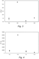
- the test electrodes 11 showed a specific capacitance (normalized by the catalytic layer 24 load) in a range of from about 0.5 to about 30 mF/g, as shown in Fig. 3 , which plots the average capacitance versus electrode type (11a-11d).
- test electrodes 11a, 11c, 11d were desirably in a range of from about 1.0 to about 10.0 mF/g.
- the electrodes 11b and 11d containing Al were preventively leached in a KOH (30%) solution at 80°C for 2 hours.
- the test electrodes 11 were each initially conditioned by performing 2 hours of anodic polarization at 10 kA/m 2 . Successively, a chronopotentiometric step was performed, by applying a cathodic current of 120 A/m 2 until the electrode potential was recorded as -0.8V vs SHE (standard hydrogen electrode). The total amount of charge released from the test electrode 11 was then calculated by integrating the current over time.
- test electrodes 11 were able to release a controlled charge (normalized by the coating load) in a range of from about 1,000 to about 70,000 mC/g, as shown in Fig. 4 , which plots the normalized average charge versus electrode type (11a-11d).
- the test electrodes 11a, 11c and 11d were desirably in a range of from about 2,000 to about 10,000 mC/g.
- more than 90 percent by weight of nickel in the catalytic layer is in its metal form while up to 10 percent by weight of nickel is in its oxide form, predomently NiO, i.e. in the latter case, the weight percentage refers to NiO.
- the metallic nickel content in the catalytic layer is in the range from 90 to 99.5 wt%, preferably in the range from 95 to 99 wt.%.
- the nickel oxide content in the catalytic layer can be in a range from at least 0.5 wt% to 10 wt% and is preferably in the range from 1 to 5 wt%.
- the optimal performances of the electrode configuration is due to the controlled charge release from the porous nickel layer. Also, a certain amount of porosity of the nickel/nickel oxide layer is desired in order to enhance the number of accessible catalytic sites. It can be expected that the relation between porosity and charge release will vary depending on nature of the layer.
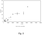
- the control of the porosity/capacitance is used to control electrode robustness (charge). As shown in Fig. 5 , which plots average capacitance (y-axis) versus average charge (x-axis) for electrodes 11a-11d, a linear relationship exists between capacitance and released charge for the electrodes 11 having a catalytic layer 24. It was thus demonstrated that the examined electrode configurations are characterized by the same, appropriate relationship between porosity/capacitance and charge release.
- the active composition 26 includes one or more metals selected from the group consisting of iridium (Ir), cobalt (Co), rhodium (Rh), Iron (Fe), Platinum (Pt), Lithium (Li), manganese (Mn).
- the iridium in the active composition 26 may be an iridium compound, such as iridium oxide (IrO 2 ).
- the cobalt in the active composition 26 may be a cobalt compound, such as a cobalt oxide, namely cobalt (II) oxide (CoO) or cobalt (II, III) oxide (Co 3 O 4 ), or nickel cobaltite (NiCo 2 O 4 ).
- cobalt that is in the active composition 26 is nickel cobaltite.
- nickel cobaltite that is in the active composition 26 is in the form of spinels.
- the rhodium in the active composition 26 may be a rhodium compound, such as rhodium (III) oxide (Rh 2 O 3 );
- the manganese in the active composition 26 may be a manganese compound, such as manganese oxide (MnO 2 );
- the iron in the active composition 26 may be an iron compound, such as iron oxide (Fe 2 O 3 ) or Fe 3 O 4 ;
- the platinum in the active composition 26 may be a platinum compound, such as platinum oxide (PtO 2 );
- the lithium in the active composition 26 may be a mixed compound, such as lithium nickel oxide (LiNiO 2 ).
- the active composition 26 may consist essentially of a cobalt compound, a nickel compound, an iridium compound, a lithium compound (e.g. lithium nickel oxide), or an iron compound (e.g. iron oxide).
- the active composition 26 may consist essentially of a cobalt compound and an iridium compound, or the active composition 26 may comprise a cobalt compound or an iridium compound or both a cobalt compound and an iridium compound.
- the active composition 26 comprises a cobalt compound or an iridium compound, more preferably both a cobalt compound and an iridium compound, still more preferably the active composition 26 comprises nickel cobaltite and iridium oxide.
- the active composition 26 may comprise: 0-100 mole percent of an iridium compound, 0-100 mole percent of a cobalt compound and 0-40 mole percent of one or more transition metal compounds selected from the group consisting of a rhodium compound, a manganese compound, an iron compound, a platinum compound, a lithium compound. More preferably, the active composition 26 may comprise: about 10-50 mole percent of an iridium compound, about 40-90 mole percent of a cobalt compound and 0-20 mole percent of one or more transition metal compounds selected from the group consisting of a rhodium compound, a manganese compound, an iron compound, a platinum compound, a lithium compound.
- the active composition 26 may comprise: about 10-30 mole percent of an iridium compound, more than 70 mole percent of a cobalt compound and 0-10 mole percent of one or more transition metal compounds selected from the group consisting of a rhodium compound, a manganese compound, an iron compound, a platinum compound, a lithium compound. Still more preferably, the active composition 26 may comprise: 10-30 mole percent of an iridium compound, 70-90 mole percent of a cobalt compound and 0-10 mole percent of one or more transition metal compounds selected from the group consisting of a rhodium compound, a manganese compound, an iron compound, a platinum compound, a lithium compound.
- the catalytic layer 24 and the active layer 26, taken together as a combination, comprise from about 80 mole percent to about 99.9 mole percent nickel, from 0 to about 2 mole percent nickel oxide, from about 0 mole percent to about 0.8 mole percent of an iridium compound, from about 0 mole percent to about 2 mole percent of a cobalt compound, and from about 0 to about 2 mole percent of one or more transition metal compounds selected from the group consisting of a rhodium compound, a manganese compound, an iron compound, a platinum compound, a lithium compound.
- the active composition 26 may be formed from one single precursor composition that is applied to the catalytic layer 24 in one or more application processes, or the active composition 26 may be formed from a plurality of different precursor compositions that are applied to the catalytic layer 24 in a plurality of application processes. As set forth above, the active composition 26 may form a layer on top of the catalytic layer 24 as schematically depicted in Fig. 2 and/or the active composition 26 may be absorbed into the catalytic layer 24 and become distributed throughout the porosity of the catalytic layer 24. In this manner, the layer of the active composition 26 may have a thickness from about 0 to about 20 ⁇ m, more preferably from about 0 to about 10 ⁇ m.
- the precursor composition(s) include precursor compounds (such as organic or inorganic metal salts) that are thermally decomposable to form the metal compounds in the active composition 26.
- the metal salts may be chlorides and may be dissolved in solvents, including acids (such as hydrochloric acid and nitric acid) and alcohols, such as isopropyl alcohol, n-propyl alcohol, n-butyl alcohol and ethyl alcohol.
- the precursor compound(s) may include the chloride, sulfate or nitrate salt of iridium dissolved in a solvent, such as an acid or an alcohol. More specifically, the precursor compound(s) may include a solution of iridium (III) chloride (IrCl 3 ) in its trihydrate form (IrCl 3 (H 2 O) 3 ), together with hydrochloric acid and isopropyl alcohol and/or ethyl alcohol.
- a solvent such as an acid or an alcohol.
- the precursor compound(s) may include a solution of iridium (III) chloride (IrCl 3 ) in its trihydrate form (IrCl 3 (H 2 O) 3 ), together with hydrochloric acid and isopropyl alcohol and/or ethyl alcohol.
- the precursor compound(s) may include cobalt chloride (CoCl 2 ) and water.
- the precursor compound(s) may include cobalt (II) acetate tetrahydrate (C 4 H 6 CoO 4 _4H 2 O), ethyl alcohol and oxalic acid (C 2 H 2 O 4 ).
- the precursor compound(s) may include nickel (II) acetate tetrahydrate (C 4 H 6 NiO 4 _4H 2 O) and cobalt (II) acetate tetrahydrate (C 4 H 6 CoO 4_ 4H 2 O) mixed with urea (CO(NH 2 ) 2 , deionized water, ethyl alcohol, glycerol and tetraethylene glycol (TEG), wherein the nickel (II) acetate and the cobalt (II) acetate are co-precipitated.
- nickel (II) acetate tetrahydrate C 4 H 6 NiO 4 _4H 2 O
- cobalt (II) acetate tetrahydrate C 4 H 6 CoO 4_ 4H 2 O
- urea CO(NH 2 ) 2
- the precursor compound(s) may include nickel (II) nitrate hexahydrate (Ni(NO 3 ) 2 ⁇ 6H 2 O) and cobalt(II) nitrate hexahydrate (Co(NO 3 ) 2 ⁇ 6H 2 O), which may be dissolved in NH 4 OH.
- the precursor composition(s) may be applied to the catalytic layer 24 using a brush, or by electrospraying, roller coating or dip coating.
- the substrate 22 coated with the catalytic layer 24 and the precursor composition(s) is heated to thermally decompose the precursor compound(s) to form the active composition 26.
- the heating may take place in an oven at a temperature of from about 300°C to about 500°C for a period of from about 10 to about 20 minutes.
- the sprayed wire mesh was heated in an oven at 350°C for 15 minutes in air.
- the plasma-sprayed woven mesh was allowed to cool and then was coated with a precursor composition, by means of a brush, in a series of coating, heating and cooling steps.
- the precursor composition comprised 19.77 g of nickel(II) nitrate hexahydrate and 39.56 g of cobalt(II)/nitrate hexahydrate, brought to a volume of 100mL with DI water. Initially, the plasma-sprayed wire mesh was coated with the precursor composition and then heated in air in an oven at 350°C for 15 minutes. After cooling, the wire mesh was again coated with the precursor composition and again heated in the oven at 350°C for 15 minutes. This process of coating, heating and cooling was repeated to achieve a load of 7.52 g METAL /m 2 .
- the foregoing process produced an electrode E1 having, on each side, a catalytic layer and an active composition.
- the catalytic layer was mostly nickel with a small amount of NiO.
- the active composition comprised 0.0427 mol/ m 2 of nickel cobaltite.
- SEM scanning electron microscope
- the combination of the catalytic layer and the active composition had a thickness (on one side) of 51 ⁇ 6 ⁇ m and had a porosity of 0.3 m 2 /g (BET).
- the combination comprised 97.6 mole percent nickel, 0.9 mole percent nickel oxide and 1.5 mole percent nickel cobaltite.
- a 100X100 mm piece of nickel expanded mesh was plasma sprayed with 99.9% purity nickel powder with a particle size of -45 / +10 ⁇ m (Fe ⁇ 0.5, O ⁇ 0.4, C ⁇ 0.02, S ⁇ 0.01 in ambient air on both sides in an amount of 4.5 ⁇ 0.5 g/dm 2 and with a target thickness of 45 ⁇ m (on each side). Afterwards, the sprayed wire mesh was heated in an oven at 350°C for 15 minutes in air. The plasma-sprayed expanded mesh was allowed to cool and then was coated with first and second precursor compositions, as described below.
- the first precursor compostion was the same as the precursor composition applied in Example 1, i.e. the solution of nickel (II) nitrate hexahydrate and cobalt (II) nitrate hexahydrate.
- the first precursor composition was also applied to the mesh in the same manner as in Example 1 to achieve a load of 7.52 g METAL /m 2 .
- the second precursor composition comprised 4.27g of hexa-ammineiridium(III) hydroxide [Ir(NH 3 ) 6 ](OH) 3 brought to a volume of 100mL with deionized water.
- the second precursor composition was applied by brush in a series of coating, heating and cooling steps. Initially, the plasma-sprayed and coated mesh was coated with the second precursor compositions and then heated in an oven at 350°C for 15 minutes in air. After cooling, the mesh was again coated with the second precursor composition and again heated in the oven at 350°C for 15 minutes. This process of coating, heating and cooling was repeated to achieve a load of 1.88 g METAL /m 2 .
- the foregoing process produced an electrode E2 having, on each side, a catalytic layer and an active composition.
- the catalytic layer was mostly nickel with a small amount of NiO.
- the active composition was 9.78 mmol/m 2 of iridium oxide and 42.7 mmol/m 2 of nickel cobaltite, which corresponds to 18.6 mole percent iridium oxide and 81.4 mole percent nickel cobaltite.
- SEM scanning electron microscope
- the catalytic layer was a nickel matrix formed by nickel particles and a thin crust of NiO, with the iridium oxide and the nickel cobaltite being distributed into the porosity of the catalytic layer.
- the combination of the catalytic layer and the active composition had a thickness (on one side) of just less than 50 ⁇ m and had a porosity of 0.4 m 2 /g (BET).
- the combination comprised comprised 98.8 mole percent nickel, 0.12 mole percent iridium oxide and 0.53 mole percent cobaltite.
- a 100X100 mm piece of nickel expanded mesh was plasma sprayed with 99.9% purity nickel powder with a particle size of -45 / +10 ⁇ m (Fe ⁇ 0.5, O ⁇ 0.4, C ⁇ 0.02, S ⁇ 0.01 in ambient air on both sides in an amount of 4.5 ⁇ 0.5 g/dm 2 and with a target thickness of 45 ⁇ m (on each side). Afterwards, the sprayed expanded mesh was heated in an oven at 350°C for 15 minutes in air. The plasma-sprayed expanded mesh was then allowed to cool and then was coated with a precursor composition, by means of a brush in a series of coating, heating and cooling steps.
- the precursor composition was the same as the second precursor composition of Example 2, i.e., hexa-ammineiridium(III) hydroxide [Ir(NH 3 ) 6 ](OH) 3 brought to a volume of 100mL with deionized water. Initially, the plasma-sprayed expanded mesh was coated with the precursor composition and then heated in an oven at 350°C for 15 minutes in air. After cooling, the mesh was again coated with the precursor composition and again heated in the oven at 350°C for 15 minutes. This process of coating, heating and cooling was repeated to achieve a load of 1.88 g METAL /m 2 .
- the foregoing process produced an electrode E3 having, on each side, a catalytic layer and an active composition.
- the catalytic layer was mostly nickel with a small amount of NiO.
- the active composition was 9.78 mmol/m 2 of iridium oxide.
- SEM scanning electron microscope
- the catalytic layer was a nickel matrix formed by nickel particles and a thin crust of NiO, with the iridium oxide being distributed into the porosity of the catalytic layer (see Figures 6 - 8 ).
- the combination of the catalytic layer and the active composition had a thickness (on each side) of just less than 50 ⁇ m and had a porosity of 0.4 m 2 /g (BET).
- the combination comprised comprised 98.7 mole percent nickel, 0.9 mole percent nickel oxide and 0.4 mole percent iridium oxide.
- a 100X100 mm piece of nickel expanded mesh was plasma sprayed with 99.9% purity nickel powder with a particle size of -45 / +10 ⁇ m (Fe ⁇ 0.5, O ⁇ 0.4, C ⁇ 0.02, S ⁇ 0.01 in ambient air on both sides in an amount of 13.0 ⁇ 0.9 g/dm 2 and with a target thickness of 300 ⁇ m and 100 ⁇ m on the other side.
- the sprayed mesh was heated in an oven at 350°C for 15 minutes.
- the sprayed expanded mesh was then allowed to cool, thereby forming an electrode CE1 with only a catalytic layer comprising nickel and nickel oxide.
- the catalytic layer had a thickness (on each side) of just less than 200 ⁇ m and had a porosity of 0.4 m 2 /g (BET).
- a 100X100 mm piece of nickel expanded mesh was plasma sprayed with 99.9% purity nickel powder with a particle size of -45 / +10 ⁇ m (Fe ⁇ 0.5, O ⁇ 0.4, C ⁇ 0.02, S ⁇ 0.01 in ambient air on both sides in an amount of 4.5 ⁇ 0.5 g/dm 2 and with a target thickness of 45 ⁇ m.
- the sprayed expanded mesh was heated in an oven at 350°C for 15 minutes.
- the sprayed wire mesh was then allowed to cool, thereby forming an electrode CE2 with only a catalytic layer comprising nickel and nickel oxide.
- the catalytic layer had a thickness (on one side) of just less than 50 ⁇ m and had a porosity of 0.4 m 2 /g (BET).
- Example 2 was re-performed on another 100X100 mm piece of nickel expanded mesh.
- the mesh was not plasma sprayed, or otherwise coated with a layer of nickel/nickel oxide or other metal.
- the active composition was formed directly on the expanded mesh.
- the same first and second precursor compositions were applied to the expanded mesh in the same manner as in Example 2, except the there was no plasma sprayed layer.
- the process produced an electrode CE3 having, on each side, an active composition.
- the active composition was 9.78 mmol/m 2 of iridium oxide and.42.7 mmol/m 2 of nickel cobaltite, which corresponds to 18.6 mole percent iridium oxide and 81.4 mole percent nickel cobaltite.
- the electrodes E1, E2, E3, , CE1, CE2 and CE3 were each used as anodes in electrolysis cells and the oxygen overvoltages at the anodes were measured in KOH 25% at 80°C with a three electrodes set-up, using a SCE reference electrode and a VMP3 Biologic potentiostat equipped with a 20A Booster.
- the iR drop was measured by means of Electrochemical Impedance Spectroscopy (EIS).
- EIS Electrochemical Impedance Spectroscopy
- the resulting electrode potential determined at 10 kA/m 2 was subtracted by the thermodynamic oxygen evolution potential at pH14. Results of these measurements are shown in Table 1 below.
- electrolysis cells with the E2, E3, CE1, CE2 and CE3 anodes, respectively were connected to receive electric power having a current of 10 kA/m 2 and were then subjected to a series of 50 shutdowns of electric power, with on/off cycles of the duration of 6 hours.
- the voltages at 10 kA/m 2 of the cells were measured after each shutdown. The results of these measurements are also shown in Table 1 below.
- the results of the tests show that while the catalytic layer of electrode CE2 is substantially thinner than the catalytic layer of electrode CE1 ( ⁇ 50 ⁇ m versus ⁇ 200 ⁇ m), the oxygen overvoltage of electrode CE2 was not that much greater than electrode CE1 (380 mV versus 350 mV).
- the electrodes E1-E3 had substantially better oxygen overvoltages than both the electrodes CE1 and CE2.
- the electrode E2 had significantly better oxygen overvoltage than CE1 and CE2 and had better shutdown tolerance than the electrodes E3, and CE3.
- the electrode CE3 had good oxygen overvoltage, but not very good shutdown tolerance.
- the results show that an electrode with only the active composition 26, without the catalytic layer 24, has a good oxygen overvoltage, but poor shutdown tolerance.
- electrodes with only catalytic layer 24, without the active composition 26, has good shutdown tolerance, but poor overvoltage.
- the synergic combination of catalytic layer 24 and active composition 26 yields an electrode with enhanced properties, i.e. both good shutdown tolerance and good overvoltage., particularly an active layer comprising both a cobalt compound and an iridium compound.
- Such an electrode e.g. electrode E2 also has an improved oxygen overvoltage.
- Figures 6 to 8 show SEM/EDAX images of a cross-section of an electrode according to Example 3 which comprises a nickel substrate 30, a catalytic layer 31 made from nickel and a small amount of nickel oxide and an iridium-based active composition thermally applied to the catalytic coating.
- the SEM image of Fig. 6 shows the morphology of the catalytic layer which was obtained by depositing nickel on a substrate made of a coarse nickel mesh via thermal spray.
- the catalytic layer 31 which exhibits some porosity is clearly distinguished by a well-defined interface 32 from the dense nickel substrate 30 which exhibits essentially no porosity.
- the porosity of the catalytic layer 31 essentially results from cracks 33 being formed within the catalytic layer 31.
- these cracks 33 are essentially orientated parallel to the interface 32 between substrate 30 and catalytic layer.
- the black area 34 corresponds to a resin required for sample preparation.
- the active composition (not visible in Fig. 6 ) can penetrate into the catalytic layer via cracks 33 as can be taken from the SEM/EDAX image of Fig. 7 which shows the same cross-sectional region of the electrode as Fig. 6 .
- Gray areas correspond to nickel of the catalytic layer while white areas/dots correspond to iridium of the active composition.
- Fig. 8 is an SEM/EDAX image showing the oxygen distribution in the same region of the electrode of Fig. 6 .
- the oxygen EDAX image (white) is overlaid to the SEM image (gray) of Fig. 6 .
Landscapes
- Chemical & Material Sciences (AREA)
- Engineering & Computer Science (AREA)
- Chemical Kinetics & Catalysis (AREA)
- Materials Engineering (AREA)
- Metallurgy (AREA)
- Organic Chemistry (AREA)
- Electrochemistry (AREA)
- Plasma & Fusion (AREA)
- Physics & Mathematics (AREA)
- Mechanical Engineering (AREA)
- Inorganic Chemistry (AREA)
- Electrodes For Compound Or Non-Metal Manufacture (AREA)
- Catalysts (AREA)
- Investigating Or Analyzing Materials By The Use Of Electric Means (AREA)
- Battery Electrode And Active Subsutance (AREA)
- Electrolytic Production Of Non-Metals, Compounds, Apparatuses Therefor (AREA)
Claims (15)
- Elektrode zur Verwendung in einem alkalischen Elektrolyseverfahren, wobei die Elektrode umfasst:ein Metallsubstrat;eine katalytische Schicht, die auf dem Metallsubstrat angeordnet ist, wobei die katalytische Schicht Nickel und Nickeloxid umfasst und eine Porosität von weniger als etwa 1 m /g, gemessen nach BET, aufweist; undeine aktive Zusammensetzung, die sowohl auf als auch innerhalb der katalytischen Schicht angeordnet ist, wobei die aktive Zusammensetzung eine oder mehrere Metallverbindungen umfasst, ausgewählt aus der Gruppe bestehend aus einer Kobaltverbindung, einer Iridiumverbindung, einer Rhodiumverbindung, einer Eisenverbindung, einer Platinverbindung, einer Lithiumverbindung und einer Manganverbindung.
- Elektrode gemäß Anspruch 1, wobei die Elektrode eine Doppelschichtkapazität, bezogen auf die Beladung der katalytischen Schicht mit dem Metall, in einem Bereich von etwa 1,0 bis etwa 10,0 mF/g aufweist.
- Elektrode gemäß Anspruch 1 oder 2, wobei die aktive Zusammensetzung mehr als 30 Molprozent der Kobaltverbindung oder der Iridiumverbindung umfasst.
- Elektrode gemäß Anspruch 3, wobei die aktive Zusammensetzung mehr als 60 Molprozent der Kobaltverbindung oder der Iridiumverbindung umfasst, und wobei die Kobaltverbindung Nickelkobaltit und die Iridiumverbindung Iridiumoxid umfasst, wobei die aktive Zusammensetzung vorzugsweise im Wesentlichen aus Nickelkobaltit besteht oder wobei die aktive Zusammensetzung vorzugsweise im Wesentlichen aus Iridiumoxid besteht.
- Elektrode gemäß Anspruch 1, wobei die aktive Zusammensetzung von etwa 40 bis etwa 90 Molprozent der Kobaltverbindung, von etwa 0 bis etwa 50 Molprozent der Iridiumverbindung und von etwa 0 bis etwa 20 Molprozent einer oder mehrerer der Rhodiumverbindung, der Eisenverbindung, der Platinverbindung, der Lithiumverbindung und der Manganverbindung umfasst.
- Elektrode gemäß Anspruch 5, wobei die aktive Zusammensetzung etwa 70 bis etwa 90 Mol-% der Kobaltverbindung, etwa 10 bis etwa 30 Mol-% der Iridiumverbindung und etwa 0 bis etwa 10 Mol-% einer oder mehrerer der Rhodiumverbindung, der Eisenverbindung, der Platinverbindung, der Lithiumverbindung und der Nickelverbindung umfasst,
wobei die Kobaltverbindung vorzugsweise Nickelkobaltit umfasst und die Iridiumverbindung Iridiumoxid umfasst. - Elektrode gemäß Anspruch 1, wobei die aktive Zusammensetzung eine oder mehrere Metallverbindungen umfasst, die aus der Gruppe ausgewählt sind, die aus Nickelkobaltit, Iridiumoxid, Eisenoxid und Lithiumnickeloxid besteht.
- Elektrode gemäß Anspruch 1-7, wobei die katalytische Schicht eine Dicke im Bereich von etwa 10 µm bis etwa 50 µm aufweist.
- Elektrode gemäß den Ansprüchen 1-8, wobei das Metallsubstrat der Elektrode ein oder mehrere Metalle umfasst, die aus der Gruppe ausgewählt sind, die aus Nickel, Nickellegierungen und Eisenlegierungen besteht.
- Elektrode gemäß Anspruch 9, wobei die katalytische Schicht eine erste katalytische Schicht ist und wobei das Metallsubstrat ein Nickelsubstrat umfasst;wobei das Metallsubstrat eine erste und eine zweite Seite aufweist, die einander gegenüberliegen, wobei die erste katalytische Schicht auf der ersten Seite des Metallsubstrats angeordnet ist und an dieser haftet;wobei die Elektrode ferner eine zweite katalytische Schicht umfasst, die auf der zweiten Seite des Metallsubstrats angeordnet ist und daran haftet, wobei die zweite katalytische Schicht im Wesentlichen die gleiche Zusammensetzung wie die erste katalytische Schicht aufweist; undwobei die aktive Zusammensetzung sowohl auf als auch innerhalb der zweiten katalytischen Schicht angeordnet ist.
- Alkalische Wasserelektrolyseeinheit, umfassend die Elektrode nach den Ansprüchen 1-10, wobei die Elektrode eine Anode ist und wobei die alkalische Wasserelektrolyseeinheit ferner umfasst:eine Kathode; undeine Elektrolytlösung, die im Wesentlichen chlorfrei ist.
- Verfahren zur Herstellung einer Elektrode, umfassend:Bereitstellung eines Metallsubstrats;Ausbilden einer katalytischen Schicht auf dem Metallsubstrat durch thermisches Spritzen, Laserplattieren oder Elektroplattieren, wobei die katalytische Schicht Folgendes umfasstNickel und Nickeloxid und mit einer Porosität von weniger als etwa 1 m /g, gemessen nach BET; undAufbringen einer aktiven Zusammensetzung auf die katalytische Schicht, wobei der Schritt des Aufbringens der aktiven Zusammensetzung das Aufbringen einer oder mehrerer Vorläuferzusammensetzungen auf die katalytische Schicht und dann das Erhitzen der einen oder mehreren Vorläuferzusammensetzungen und der katalytischen Schicht zur Bildung der aktiven Zusammensetzung umfasst.
- Verfahren gemäß Anspruch 12, wobei der Schritt der Bildung der katalytischen Schicht durch thermisches Sprühen durchgeführt wird und die katalytische Schicht eine Doppelschichtkapazität in einem Bereich von etwa 1,0 bis etwa 10,0 mF/g aufweist.
- Verfahren gemäß Anspruch 12 oder 13, wobei der Schritt der Bildung der katalytischen Schicht durch thermisches Spritzen durchgeführt wird und das elektrische Draht- oder Plasmaspritzen von Nickelpulver auf das Metallsubstrat in Umgebungsluft umfasst,
wobei die aktive Zusammensetzung vorzugsweise eine oder mehrere Metallverbindungen umfasst, ausgewählt aus der Gruppe, bestehend aus einer Kobaltverbindung, einer Iridiumverbindung, einer Rhodiumverbindung, einer Eisenverbindung, einer Platinverbindung, einer Lithiumverbindung und einer Manganverbindung, und die Vorläuferzusammensetzung Vorläufer der einen oder mehreren Metallverbindungen umfasst. - Verfahren gemäß Anspruch 14, wobei die aktive Zusammensetzung etwa 40 bis etwa 90 Molprozent der Kobaltverbindung und etwa 10 bis etwa 50 Molprozent der Iridiumverbindung umfasst, wobei die Kobaltverbindung vorzugsweise Nickelkobaltit umfasst und die Iridiumverbindung Iridiumoxid umfasst.
Applications Claiming Priority (2)
| Application Number | Priority Date | Filing Date | Title |
|---|---|---|---|
| IT102020000020587A IT202000020587A1 (it) | 2020-08-28 | 2020-08-28 | Electrode with enhanced shutdown tolerance- elettrodo con tolleranza agli arresti migliorata |
| PCT/EP2021/073772 WO2022043509A1 (en) | 2020-08-28 | 2021-08-27 | Electrode with enhanced shutdown tolerance |
Publications (3)
| Publication Number | Publication Date |
|---|---|
| EP4204604A1 EP4204604A1 (de) | 2023-07-05 |
| EP4204604B1 true EP4204604B1 (de) | 2024-10-02 |
| EP4204604C0 EP4204604C0 (de) | 2024-10-02 |
Family
ID=73005726
Family Applications (1)
| Application Number | Title | Priority Date | Filing Date |
|---|---|---|---|
| EP21763107.6A Active EP4204604B1 (de) | 2020-08-28 | 2021-08-27 | Elektrode mit verbesserter abschalttoleranz |
Country Status (13)
| Country | Link |
|---|---|
| US (1) | US20240035179A1 (de) |
| EP (1) | EP4204604B1 (de) |
| JP (1) | JP2023543388A (de) |
| KR (1) | KR20230058141A (de) |
| CN (1) | CN116234941A (de) |
| AU (1) | AU2021335074A1 (de) |
| CA (1) | CA3193461A1 (de) |
| ES (1) | ES2994128T3 (de) |
| IL (1) | IL300672A (de) |
| IT (1) | IT202000020587A1 (de) |
| TW (1) | TWI890846B (de) |
| WO (1) | WO2022043509A1 (de) |
| ZA (1) | ZA202301318B (de) |
Families Citing this family (2)
| Publication number | Priority date | Publication date | Assignee | Title |
|---|---|---|---|---|
| KR20240113932A (ko) * | 2022-03-31 | 2024-07-23 | 드 노라 페르멜렉 가부시키가이샤 | 전해용 전극 및 그 제조 방법 |
| DE102024200876A1 (de) | 2024-01-31 | 2025-07-31 | Siemens Energy Global GmbH & Co. KG | Verfahren zur Herstellung einer Elektrode mit einem Edelmetall-Katalysator für die alkalische Wasserelektrolyse |
Family Cites Families (12)
| Publication number | Priority date | Publication date | Assignee | Title |
|---|---|---|---|---|
| JPS60159184A (ja) * | 1984-01-27 | 1985-08-20 | Agency Of Ind Science & Technol | 水電解用陽極 |
| DE3743354A1 (de) * | 1987-12-21 | 1989-06-29 | Kernforschungsanlage Juelich | Verfahren zur herstellung von poroesen elektroden |
| JP2015086420A (ja) * | 2013-10-29 | 2015-05-07 | 国立大学法人横浜国立大学 | アルカリ水電解用陽極 |
| JP6788378B2 (ja) * | 2016-05-17 | 2020-11-25 | 旭化成株式会社 | 水電解セル及び複極式水電解槽 |
| EP3296431A1 (de) * | 2016-09-15 | 2018-03-21 | Ecole Polytechnique Fédérale de Lausanne (EPFL) | Verfahren zur synthese einer elektrode zur verwendung als katalysator einer sauerstoffentwicklungsreaktion |
| JP2018154879A (ja) * | 2017-03-17 | 2018-10-04 | 株式会社東芝 | 電気化学反応装置および電気化学反応装置用アノードの製造方法 |
| JP6837130B2 (ja) * | 2017-03-31 | 2021-03-03 | 旭化成株式会社 | 陽極、複極式電解セル、水素製造方法 |
| KR102232627B1 (ko) * | 2018-03-07 | 2021-03-25 | 드 노라 페르멜렉 가부시키가이샤 | 전해용 전극 및 그의 제조 방법 |
| JP7260272B2 (ja) * | 2018-09-21 | 2023-04-18 | 旭化成株式会社 | 電極の製造方法 |
| US11339486B2 (en) * | 2019-03-11 | 2022-05-24 | The University Of Akron | Porous amorphous metallic electrocatalytic materials for water electrolysis |
| CN110656349B (zh) * | 2019-09-29 | 2021-10-29 | 安徽师范大学 | 一种在泡沫镍上原位生长Fe掺杂草酸镍纳米棒、制备方法及其应用 |
| US10655235B1 (en) * | 2019-12-03 | 2020-05-19 | Haiming Li | Method for preparing a sintered nickel alkaline water electrolysis electrode |
-
2020
- 2020-08-28 IT IT102020000020587A patent/IT202000020587A1/it unknown
-
2021
- 2021-08-27 KR KR1020237010560A patent/KR20230058141A/ko active Pending
- 2021-08-27 JP JP2023513857A patent/JP2023543388A/ja active Pending
- 2021-08-27 CN CN202180052901.3A patent/CN116234941A/zh active Pending
- 2021-08-27 TW TW110131761A patent/TWI890846B/zh active
- 2021-08-27 AU AU2021335074A patent/AU2021335074A1/en active Pending
- 2021-08-27 ES ES21763107T patent/ES2994128T3/es active Active
- 2021-08-27 CA CA3193461A patent/CA3193461A1/en active Pending
- 2021-08-27 US US18/022,374 patent/US20240035179A1/en active Pending
- 2021-08-27 EP EP21763107.6A patent/EP4204604B1/de active Active
- 2021-08-27 IL IL300672A patent/IL300672A/en unknown
- 2021-08-27 WO PCT/EP2021/073772 patent/WO2022043509A1/en not_active Ceased
-
2023
- 2023-02-01 ZA ZA2023/01318A patent/ZA202301318B/en unknown
Also Published As
| Publication number | Publication date |
|---|---|
| CN116234941A (zh) | 2023-06-06 |
| ZA202301318B (en) | 2024-06-26 |
| EP4204604C0 (de) | 2024-10-02 |
| TW202208690A (zh) | 2022-03-01 |
| KR20230058141A (ko) | 2023-05-02 |
| WO2022043509A1 (en) | 2022-03-03 |
| US20240035179A1 (en) | 2024-02-01 |
| IT202000020587A1 (it) | 2022-02-28 |
| CA3193461A1 (en) | 2022-03-03 |
| IL300672A (en) | 2023-04-01 |
| AU2021335074A1 (en) | 2023-03-02 |
| ES2994128T3 (en) | 2025-01-17 |
| JP2023543388A (ja) | 2023-10-16 |
| TWI890846B (zh) | 2025-07-21 |
| EP4204604A1 (de) | 2023-07-05 |
Similar Documents
| Publication | Publication Date | Title |
|---|---|---|
| EP3444383B1 (de) | Anode für alkalische wasserelektrolyse und verfahren zur herstellung einer anode für alkalische wasserelektrolyse | |
| Hall | Alkaline water electrolysis anode materials | |
| WO2015064644A1 (ja) | アルカリ水電解用陽極 | |
| JP2023523614A (ja) | 白金族金属フリーの自立型酸素発生電極を有する陰イオン交換膜電解槽 | |
| EP4204604B1 (de) | Elektrode mit verbesserter abschalttoleranz | |
| KR20220031516A (ko) | NiCoFe 층상이중수산화물의 제조 방법, NiCoFe 층상이중수산화물, 전극, 막전극접합체 및 이를 포함하는 수전해 시스템 | |
| JP6975297B1 (ja) | アルカリ水電解用アノード | |
| US11965256B2 (en) | Anode for alkaline water electrolysis and method for producing same | |
| JP2025501727A (ja) | 酸素発生のためのニッケル系アノード | |
| Schiller et al. | Vacuum plasma sprayed electrodes for advanced alkaline water electrolysis | |
| JP7762710B2 (ja) | 電解プロセスにおけるガス発生のための電極 | |
| KR20250069750A (ko) | 이중층 수산화물 구조체, 이를 포함하는 전극 및 수전해 시스템, 및 그 제조방법 | |
| Zabielaitė et al. | Investigation of sodium borohydride and hydrazine oxidation on gold nanoparticles modified zinc–cobalt coating | |
| CN116905017A (zh) | 一种等离子喷丝制备碱性水电解用镍电极的制备方法 | |
| CN115142084A (zh) | 自支撑金属-类水滑石复合催化电极及其制备方法与应用 | |
| Endoh | Development and performance of the Raney Nickel Dispersion-plated Cathodes for Chlor-Alkali Process |
Legal Events
| Date | Code | Title | Description |
|---|---|---|---|
| STAA | Information on the status of an ep patent application or granted ep patent |
Free format text: STATUS: UNKNOWN |
|
| STAA | Information on the status of an ep patent application or granted ep patent |
Free format text: STATUS: THE INTERNATIONAL PUBLICATION HAS BEEN MADE |
|
| PUAI | Public reference made under article 153(3) epc to a published international application that has entered the european phase |
Free format text: ORIGINAL CODE: 0009012 |
|
| STAA | Information on the status of an ep patent application or granted ep patent |
Free format text: STATUS: REQUEST FOR EXAMINATION WAS MADE |
|
| 17P | Request for examination filed |
Effective date: 20230209 |
|
| AK | Designated contracting states |
Kind code of ref document: A1 Designated state(s): AL AT BE BG CH CY CZ DE DK EE ES FI FR GB GR HR HU IE IS IT LI LT LU LV MC MK MT NL NO PL PT RO RS SE SI SK SM TR |
|
| DAV | Request for validation of the european patent (deleted) | ||
| DAX | Request for extension of the european patent (deleted) | ||
| GRAP | Despatch of communication of intention to grant a patent |
Free format text: ORIGINAL CODE: EPIDOSNIGR1 |
|
| STAA | Information on the status of an ep patent application or granted ep patent |
Free format text: STATUS: GRANT OF PATENT IS INTENDED |
|
| RIC1 | Information provided on ipc code assigned before grant |
Ipc: C23C 4/18 20060101ALI20240319BHEP Ipc: C23C 4/08 20160101ALI20240319BHEP Ipc: C25B 11/093 20210101ALI20240319BHEP Ipc: C25B 11/091 20210101ALI20240319BHEP Ipc: C25B 11/061 20210101ALI20240319BHEP Ipc: C25B 11/056 20210101ALI20240319BHEP Ipc: C25B 11/053 20210101ALI20240319BHEP Ipc: C25B 11/031 20210101ALI20240319BHEP Ipc: C25B 1/04 20210101AFI20240319BHEP |
|
| INTG | Intention to grant announced |
Effective date: 20240422 |
|
| GRAS | Grant fee paid |
Free format text: ORIGINAL CODE: EPIDOSNIGR3 |
|
| GRAA | (expected) grant |
Free format text: ORIGINAL CODE: 0009210 |
|
| STAA | Information on the status of an ep patent application or granted ep patent |
Free format text: STATUS: THE PATENT HAS BEEN GRANTED |
|
| AK | Designated contracting states |
Kind code of ref document: B1 Designated state(s): AL AT BE BG CH CY CZ DE DK EE ES FI FR GB GR HR HU IE IS IT LI LT LU LV MC MK MT NL NO PL PT RO RS SE SI SK SM TR |
|
| REG | Reference to a national code |
Ref country code: GB Ref legal event code: FG4D |
|
| REG | Reference to a national code |
Ref country code: CH Ref legal event code: EP |
|
| REG | Reference to a national code |
Ref country code: DE Ref legal event code: R096 Ref document number: 602021019649 Country of ref document: DE |
|
| REG | Reference to a national code |
Ref country code: IE Ref legal event code: FG4D |
|
| U01 | Request for unitary effect filed |
Effective date: 20241024 |
|
| U07 | Unitary effect registered |
Designated state(s): AT BE BG DE DK EE FI FR IT LT LU LV MT NL PT RO SE SI Effective date: 20241107 |
|
| REG | Reference to a national code |
Ref country code: ES Ref legal event code: FG2A Ref document number: 2994128 Country of ref document: ES Kind code of ref document: T3 Effective date: 20250117 |
|
| PG25 | Lapsed in a contracting state [announced via postgrant information from national office to epo] |
Ref country code: HR Free format text: LAPSE BECAUSE OF FAILURE TO SUBMIT A TRANSLATION OF THE DESCRIPTION OR TO PAY THE FEE WITHIN THE PRESCRIBED TIME-LIMIT Effective date: 20241002 Ref country code: IS Free format text: LAPSE BECAUSE OF FAILURE TO SUBMIT A TRANSLATION OF THE DESCRIPTION OR TO PAY THE FEE WITHIN THE PRESCRIBED TIME-LIMIT Effective date: 20250202 |
|
| PG25 | Lapsed in a contracting state [announced via postgrant information from national office to epo] |
Ref country code: GR Free format text: LAPSE BECAUSE OF FAILURE TO SUBMIT A TRANSLATION OF THE DESCRIPTION OR TO PAY THE FEE WITHIN THE PRESCRIBED TIME-LIMIT Effective date: 20250103 |
|
| PG25 | Lapsed in a contracting state [announced via postgrant information from national office to epo] |
Ref country code: PL Free format text: LAPSE BECAUSE OF FAILURE TO SUBMIT A TRANSLATION OF THE DESCRIPTION OR TO PAY THE FEE WITHIN THE PRESCRIBED TIME-LIMIT Effective date: 20241002 Ref country code: CZ Free format text: LAPSE BECAUSE OF FAILURE TO SUBMIT A TRANSLATION OF THE DESCRIPTION OR TO PAY THE FEE WITHIN THE PRESCRIBED TIME-LIMIT Effective date: 20241002 |
|
| PG25 | Lapsed in a contracting state [announced via postgrant information from national office to epo] |
Ref country code: RS Free format text: LAPSE BECAUSE OF FAILURE TO SUBMIT A TRANSLATION OF THE DESCRIPTION OR TO PAY THE FEE WITHIN THE PRESCRIBED TIME-LIMIT Effective date: 20250102 |
|
| PG25 | Lapsed in a contracting state [announced via postgrant information from national office to epo] |
Ref country code: SM Free format text: LAPSE BECAUSE OF FAILURE TO SUBMIT A TRANSLATION OF THE DESCRIPTION OR TO PAY THE FEE WITHIN THE PRESCRIBED TIME-LIMIT Effective date: 20241002 |
|
| PG25 | Lapsed in a contracting state [announced via postgrant information from national office to epo] |
Ref country code: SK Free format text: LAPSE BECAUSE OF FAILURE TO SUBMIT A TRANSLATION OF THE DESCRIPTION OR TO PAY THE FEE WITHIN THE PRESCRIBED TIME-LIMIT Effective date: 20241002 |
|
| PLBE | No opposition filed within time limit |
Free format text: ORIGINAL CODE: 0009261 |
|
| STAA | Information on the status of an ep patent application or granted ep patent |
Free format text: STATUS: NO OPPOSITION FILED WITHIN TIME LIMIT |
|
| 26N | No opposition filed |
Effective date: 20250703 |
|
| U20 | Renewal fee for the european patent with unitary effect paid |
Year of fee payment: 5 Effective date: 20250827 |
|
| PGFP | Annual fee paid to national office [announced via postgrant information from national office to epo] |
Ref country code: ES Payment date: 20250926 Year of fee payment: 5 |
|
| PGFP | Annual fee paid to national office [announced via postgrant information from national office to epo] |
Ref country code: NO Payment date: 20250826 Year of fee payment: 5 |
|
| PGFP | Annual fee paid to national office [announced via postgrant information from national office to epo] |
Ref country code: GB Payment date: 20250820 Year of fee payment: 5 |
|
| PGFP | Annual fee paid to national office [announced via postgrant information from national office to epo] |
Ref country code: CH Payment date: 20250901 Year of fee payment: 5 |