EP4202170B1 - Verbinder, stossverbindung und verfahren zu deren herstellung - Google Patents
Verbinder, stossverbindung und verfahren zu deren herstellung Download PDFInfo
- Publication number
- EP4202170B1 EP4202170B1 EP22213873.7A EP22213873A EP4202170B1 EP 4202170 B1 EP4202170 B1 EP 4202170B1 EP 22213873 A EP22213873 A EP 22213873A EP 4202170 B1 EP4202170 B1 EP 4202170B1
- Authority
- EP
- European Patent Office
- Prior art keywords
- profile
- connector
- screw
- threshold
- positioning
- Prior art date
- Legal status (The legal status is an assumption and is not a legal conclusion. Google has not performed a legal analysis and makes no representation as to the accuracy of the status listed.)
- Active
Links
Images


Classifications
-
- E—FIXED CONSTRUCTIONS
- E06—DOORS, WINDOWS, SHUTTERS, OR ROLLER BLINDS IN GENERAL; LADDERS
- E06B—FIXED OR MOVABLE CLOSURES FOR OPENINGS IN BUILDINGS, VEHICLES, FENCES OR LIKE ENCLOSURES IN GENERAL, e.g. DOORS, WINDOWS, BLINDS, GATES
- E06B3/00—Window sashes, door leaves, or like elements for closing wall or like openings; Layout of fixed or moving closures, e.g. windows in wall or like openings; Features of rigidly-mounted outer frames relating to the mounting of wing frames
- E06B3/96—Corner joints or edge joints for windows, doors, or the like frames or wings
- E06B3/964—Corner joints or edge joints for windows, doors, or the like frames or wings using separate connection pieces, e.g. T-connection pieces
- E06B3/9642—Butt type joints with at least one frame member cut off square; T-shape joints
-
- E—FIXED CONSTRUCTIONS
- E06—DOORS, WINDOWS, SHUTTERS, OR ROLLER BLINDS IN GENERAL; LADDERS
- E06B—FIXED OR MOVABLE CLOSURES FOR OPENINGS IN BUILDINGS, VEHICLES, FENCES OR LIKE ENCLOSURES IN GENERAL, e.g. DOORS, WINDOWS, BLINDS, GATES
- E06B1/00—Border constructions of openings in walls, floors, or ceilings; Frames to be rigidly mounted in such openings
- E06B1/70—Sills; Thresholds
-
- E—FIXED CONSTRUCTIONS
- E06—DOORS, WINDOWS, SHUTTERS, OR ROLLER BLINDS IN GENERAL; LADDERS
- E06B—FIXED OR MOVABLE CLOSURES FOR OPENINGS IN BUILDINGS, VEHICLES, FENCES OR LIKE ENCLOSURES IN GENERAL, e.g. DOORS, WINDOWS, BLINDS, GATES
- E06B3/00—Window sashes, door leaves, or like elements for closing wall or like openings; Layout of fixed or moving closures, e.g. windows in wall or like openings; Features of rigidly-mounted outer frames relating to the mounting of wing frames
- E06B3/04—Wing frames not characterised by the manner of movement
- E06B3/06—Single frames
- E06B3/08—Constructions depending on the use of specified materials
- E06B3/20—Constructions depending on the use of specified materials of plastics
- E06B3/22—Hollow frames
- E06B3/221—Hollow frames with the frame member having local reinforcements in some parts of its cross-section or with a filled cavity
- E06B3/222—Hollow frames with the frame member having local reinforcements in some parts of its cross-section or with a filled cavity with internal prefabricated reinforcing section members inserted after manufacturing of the hollow frame
-
- E—FIXED CONSTRUCTIONS
- E06—DOORS, WINDOWS, SHUTTERS, OR ROLLER BLINDS IN GENERAL; LADDERS
- E06B—FIXED OR MOVABLE CLOSURES FOR OPENINGS IN BUILDINGS, VEHICLES, FENCES OR LIKE ENCLOSURES IN GENERAL, e.g. DOORS, WINDOWS, BLINDS, GATES
- E06B3/00—Window sashes, door leaves, or like elements for closing wall or like openings; Layout of fixed or moving closures, e.g. windows in wall or like openings; Features of rigidly-mounted outer frames relating to the mounting of wing frames
- E06B3/96—Corner joints or edge joints for windows, doors, or the like frames or wings
- E06B3/964—Corner joints or edge joints for windows, doors, or the like frames or wings using separate connection pieces, e.g. T-connection pieces
- E06B3/9641—Corner joints or edge joints for windows, doors, or the like frames or wings using separate connection pieces, e.g. T-connection pieces part of which remains visible
-
- E—FIXED CONSTRUCTIONS
- E06—DOORS, WINDOWS, SHUTTERS, OR ROLLER BLINDS IN GENERAL; LADDERS
- E06B—FIXED OR MOVABLE CLOSURES FOR OPENINGS IN BUILDINGS, VEHICLES, FENCES OR LIKE ENCLOSURES IN GENERAL, e.g. DOORS, WINDOWS, BLINDS, GATES
- E06B3/00—Window sashes, door leaves, or like elements for closing wall or like openings; Layout of fixed or moving closures, e.g. windows in wall or like openings; Features of rigidly-mounted outer frames relating to the mounting of wing frames
- E06B3/96—Corner joints or edge joints for windows, doors, or the like frames or wings
- E06B3/964—Corner joints or edge joints for windows, doors, or the like frames or wings using separate connection pieces, e.g. T-connection pieces
- E06B3/968—Corner joints or edge joints for windows, doors, or the like frames or wings using separate connection pieces, e.g. T-connection pieces characterised by the way the connecting pieces are fixed in or on the frame members
- E06B3/9687—Corner joints or edge joints for windows, doors, or the like frames or wings using separate connection pieces, e.g. T-connection pieces characterised by the way the connecting pieces are fixed in or on the frame members with screws blocking the connecting piece inside or on the frame member
-
- E—FIXED CONSTRUCTIONS
- E06—DOORS, WINDOWS, SHUTTERS, OR ROLLER BLINDS IN GENERAL; LADDERS
- E06B—FIXED OR MOVABLE CLOSURES FOR OPENINGS IN BUILDINGS, VEHICLES, FENCES OR LIKE ENCLOSURES IN GENERAL, e.g. DOORS, WINDOWS, BLINDS, GATES
- E06B1/00—Border constructions of openings in walls, floors, or ceilings; Frames to be rigidly mounted in such openings
- E06B1/70—Sills; Thresholds
- E06B2001/707—Thresholds with special provision for insulation
Definitions
- the invention relates to a connector for connecting a post profile to a threshold or a frame profile, in particular for connecting to the glass receiving profile received in a threshold profile, comprising a base plate, on the surface of which, preferably at a right angle to the surface, a fastening tab is arranged, in particular which can be fastened to a rebate surface of a post profile, wherein the fastening tab has at least one fastening hole by means of which the fastening tab can be fastened to the rebate surface, wherein the connector has at least one screw channel opening into the fastening tab, in particular a screw channel shaped like a pocket hole, which extends through the base plate at an acute angle, preferably at an angle between 10° and 30°, more preferably between 10° and 20° to the fastening tab.
- the invention also relates to a butt joint between a threshold or a frame profile and a post profile, in particular for lift-sliding doors, and a method for producing a butt joint.
- the threshold that can be used in the invention can preferably be formed by a threshold profile and a glass receiving profile received therein.
- the frame profile is preferably the profile of a frame that runs parallel to the threshold and above it.
- the butt joint thus comprises the threshold or the frame profile with a post profile arranged perpendicular to the threshold/frame profile, e.g. post profile, which is fixed to the threshold/frame profile via a connector, with a fastening tab on the connector Stiffening rib is formed.
- This fastening tab has at least one fastening hole through which the fastening tab can be attached to the rebate surface of the post profile.
- bore as used in this description of the invention is not intended to imply that production is carried out by drilling, although this is possible.
- a preformed recess that acts like a bore is also referred to as such.
- Post profiles are usually connected at the front end to the horizontally running profiles, such as floor sills or upper frame profiles, by means of connectors, in particular cast connectors, preferably made of die-cast metal, in particular die-cast zinc.
- a connector of the type mentioned above is known, for example, from the publication EN 10 2010 062 751 A1 .
- the object of the invention is therefore to propose a connector that offers a fastening option that protrudes into the glazing rebate space with little space requirement and enables good positioning.
- the entire glass rebate area is required as a glass recess.
- a connector according to claim 1 This opens up the possibility that the connector can first be fastened to the post profile. Fastening can then take place using the at least one screw channel, in particular using the at least one screw channel shaped like a pocket hole from the top of the threshold or a frame profile.
- the mechanical load alone results in greater positioning accuracy when screwing to the threshold/frame profile, with the screw channel creating improved guidance of the screw, which cannot be achieved with conventional screw holes in simple metal sheets.
- Pocket hole drilling is known from the field of wood joinery. To create a pocket hole in wood, a hole is drilled into a workpiece at an angle - usually 15 degrees - and then connected to a second workpiece with a self-tapping screw.
- the invention transfers this principle in the preferred embodiment of the screw channel shaped like a pocket hole to the construction of a connector, which is preferably designed as a cast component, preferably as a metallic cast component, in particular as a die-cast component, e.g. made of die-cast zinc.
- the connector can also be designed as a plastic injection-molded component.
- the design such that the screw channel is preferably shaped like a pocket hole is intended to express that the screw channel does not necessarily have to be created by drilling in the connector, although this can also be the case. What is important is that the screw channel in this preferred embodiment acts like a drilled pocket hole due to its shape.
- a key feature of a pocket hole is a screw channel that extends at an acute angle to the surface through which a screw is inserted into the screw channel, with the screw channel having a first channel diameter in its initial area that is adapted to accommodate the screw head.
- the screw channel tapers at a shoulder/step from the first channel diameter to a second, smaller channel diameter through which the screw shaft with screw thread extends.
- the underside of the screw head rests on the shoulder/step.
- the mouth opening of such a pocket hole has a longitudinal extension in the opening plane.
- Such a pocket hole is created in wood carpentry using a step drill.
- a preferred development provides that between the surface of the base plate and the inner surface of the fastening tab, preferably in an area below the upper edge of the opening of the screw channel in the fastening tab, a material accumulation is arranged, which at least partially forms the channel wall of the screw channel.
- the inner surface of the fastening tab is the surface which, in the assembled state, faces the rebate surface of the post profile.
- the screw channel is not only defined by the opening(s) in the fastening tab and the base plate, but also within the accumulation of material, so that this offers improved guidance of the screw.
- the accumulation of material acts as a stiffener, in particular as a stiffening rib between the base plate and the fastening tab.
- the surface of this accumulation of material facing away from the base plate runs between the fastening tab and the base plate at the angle that the screw channel in this accumulation of material assumes relative to these two elements.
- the material accumulation also ensures that there is enough material under the outer surface of the mounting tab for the grading of the channel. is available.
- the fastening tab can therefore be very thin in areas around the mouth opening of the screw channel or at least above the mouth opening, in particular thinner than in the area of the material accumulation, in particular with a thickness that otherwise does not allow a preferred pocket hole drilling with steps.
- the material accumulation thus acts locally like a thickening of the fastening tab and encloses the screw channel, preferably with the step as a support for a screw head.
- At least one positioning pin protrudes from the lower surface of the base plate, with the screw channel penetrating the positioning pin.
- the positioning pin forms the channel wall of the screw channel at least in part.
- a number of positioning pins corresponding to the number of screw channels is provided, in particular each screw channel provided thus penetrates its own positioning pin associated with the screw channel.
- the respective positioning pin forms that wall part of the screw channel which lies below the base plate, in particular wherein the accumulation of material forms that wall part of the screw channel which lies above the base plate.
- the material of the positioning pin and the accumulation of material can thus form a very long screw channel, which provides a very good guide for a screw, whereby the positioning pins are designed to be accommodated in prepared drill holes in the threshold, preferably in the glass receiving profile of the threshold profile.
- the aim of a quick and precise assembly of the connector, as well as a secure screw connection in the steel reinforcement of the threshold is achieved without the screw "running off”.
- the positioning pin has a fitting area directly adjacent to the lower surface of the base plate, the outer surface of which is completely or at least partially in the form a cylinder section of a cylinder with a cylinder axis running at right angles to the lower surface of the base plate.
- the invention preferably provides that the at least one drill hole is created in the floor sill or an (upper) frame profile with an inner diameter which corresponds to the outer diameter / the outer cross section of the fitting area of the positioning pin. In this way, the connector is held in position after being inserted into the at least one hole.
- the positioning pin is tapered, in particular tapered from the end of the fitting area.
- the entire positioning pin can lie within the volume of the cylinder defining the fitting area.
- the screw channel intersects the axis of the imaginary cylinder surrounding the positioning pin, preferably at the same angle as the screw channel runs to the fastening tab.
- a stop element is arranged on the inner surface of the fastening tab above the accumulation of material forming the channel wall. This allows the post profile to rest on the stop element, in particular the stop element limits how far the post profile can be pushed onto the connector in the direction of the base plate.
- a butt connection can be formed between a threshold or a frame profile and a post profile, which is formed by a connector, wherein the at least one positioning pin is inserted into a positioning hole of the threshold / frame profile, preferably into a positioning hole of a glass receiving profile received in a threshold profile, in particular, wherein the connector is anchored in the steel reinforcement of the floor sill/frame profile, in particular in the steel reinforcement of a sill profile receiving a glass receiving profile, by means of a screw penetrating the at least one screw channel, preferably designed as a pocket hole.
- the post profile is provided with a notch in the rebate surface at its free end and the connector is screwed to the rebate surface of the post profile, in particular also to the bottom surface of a fitting groove of the post profile, the edge of the notch enclosing the material accumulation or contacting the stop arranged above the material accumulation, and at least one positioning hole is set in the floor sill/frame profile, in particular in the glass receiving profile of a sill profile, and the connector with the at least one positioning pin is inserted into the at least one positioning hole and the connector is screwed to a steel profile of the floor sill/frame profile, in particular to a steel profile in the sill profile receiving the glass receiving profile, through the at least one screw channel, preferably designed like a pocket hole.
- a cover profile can preferably be clipped onto the post profile on the side of the fitting groove / Euro groove of the post profile. Even in the case of post profiles without a fitting groove, Any groove or profile irregularities on the side facing away from the rebate surface can be covered with a cover profile.
- a preferred embodiment provides that at least the material accumulation and the at least one positioning pin in the connector formed as a cast component are preformed, preferably also the at least one screw channel, in particular the at least one screw channel formed in the form of a pocket hole, is preformed.
- primary forming is usually understood to mean that these elements are created directly during the casting process, preferably in such a way that no reworking of the elements is necessary.
- the connector in principle, however, it is also possible to form the connector as a solid material during casting production and to subsequently introduce the hollow areas of the screw channel, in particular the hollow areas of the screw channel shaped like a pocket hole, and possibly also other recesses, into the solid material, in particular in zinc die-casting, by drilling, in particular with a pocket hole drill.
- the connector serves as a connecting element between the horizontal threshold on the floor and the upper, horizontal frame profile with the post profile arranged vertically between them, which can be a post profile. At the same time, the connector secures the post profile in the transverse and longitudinal directions.
- the connector is preferably first firmly connected to the post profile with contour milling at the end. During contour milling, at least the aforementioned notch is created.
- a further fastening tab is arranged at a distance from the fastening tab and parallel to it.
- a post profile can be accommodated between these fastening tabs, in particular is enclosed between them.
- fastening tabs rest on the outside of surface areas of the post profile and are not inserted into hollow chambers of the post profile that are open in the profile cross-section.
- Each fastening tab provided on the connector has at least one fastening hole through which the connector can be screwed into the post profile with a screw, preferably one that runs perpendicular to the longitudinal direction of the post profile.
- a stiffening rib can be formed on the further fastening tab, preferably on both sides, which preferably tapers towards the other fastening tab as the distance from the base plate increases and/or has a contact surface at the upper free end.
- the contact surface can be formed by a chamfer or a curve, for example.
- a stop can be formed on at least one stiffening rib, in particular on one of two stiffening ribs, which in turn limits the insertion width of the post profile.
- the further fastening tab in particular also the at least one stiffening rib, preferably both stiffening ribs formed on both sides thereof, are preferably arranged in the fitting receiving groove / Euro groove of the post profile.
- the at least one stiffening rib preferably the two stiffening ribs, not only serve to stiffen the connector, but preferably also serve to move the wing profile into an assembly position by sliding along the stiffening rib(s).
- the tapered stiffening rib(s) serving as an insertion aid and/or the aforementioned contact surface(s) on the side facing away from the glass rebate, in the example of a fitting groove/Euro groove can be used to slide onto the stiffening ribs.
- the post profile is placed on the connector in such a way that it clamps positioned between the stiffening ribs and the first mentioned fastening tab.
- the stiffening ribs are formed in pairs and spaced apart from one another such that they enclose the further vertical fastening tab between them and are firmly formed thereon.
- the stiffening ribs are preferably clamped to the fitting groove / Euro groove or other guide groove of the post profile in the created butt joint. When assembled, after the screws have been tightened, this U-shaped guide combination has a shape-stabilizing effect on the post profile.
- the connector provides at least one stop surface which, when assembled, rests flat against a corresponding second stop surface of the post profile.
- the arrangement of the stop surfaces depends on the shape of the post profile milled to the contour or vice versa.
- the finished milled post profile preferably fits flush with the shape of the connector and forms a closed unit.
- the desired end position is reached when the contour-milled stop surface of the post profile, in particular which is an area of the edge, in particular an area of the edge face, of the aforementioned notch, meets at least one stop surface of the connector.
- the connector is provided with three stops/stop surfaces, which are arranged in such a way that they provide stable support planes for the post profile to be attached. Two stop surfaces are preferably at the same height level, a third stop surface is at a different height level above the base plate. Preferably There is an analogous and corresponding arrangement of the stop surfaces of the connector with those of the contour milling on the post profile.
- clearances can preferably be provided on the connector, which are formed by a groove-shaped channel in order to allow the post profile to lie unhindered in the corner areas.
- the connector In the assembly position, the connector is secured against pulling off in the longitudinal direction by fastening elements, e.g. screws on the post profile.
- the connector preferably has at least one hole for such fastening means in each of the two fastening tabs arranged perpendicular to the base plate and opposite one another. These serve to connect to the post profile and secure it in the longitudinal direction and prevent it from being pulled off.
- the post profile is essentially flanked by the two fastening tabs that protrude perpendicular to the base plate and these clamp the post profile between them.
- fasteners are screwed from the outside through the vertical fastening tabs into the steel reinforcement of the post profile.
- the screws are positioned parallel to the floor threshold.
- the connector is preferably firmly connected to the base plate with at least one drill hole in the base plate and a fastening device arranged orthogonally to the threshold.
- the fastening devices are commercially available screws that are inserted into the threshold from above. To ensure secure fixing, the screws are always inserted into steel reinforcements. screwed in, which are installed in the hollow spaces of the plastic profiles and serve as a stable counter bearing.
- the pre-assembled post profile is positioned on the threshold with the end connector and is then firmly connected to it.
- the connector can be easily and precisely inserted into the threshold during assembly.
- the positioning pins formed on the underside of the base plate engage, for example, in the respective positioning hole in the glass support profile of the threshold.
- the connector is secured against displacement in the transverse direction by a fastening means (screw) arranged orthogonally to the threshold, with security already provided by the fit between the at least one positioning pin and the positioning hole.
- a fastening means screw
- Two fastening points on the base plate that are as far away from each other as possible are ideal.
- the fastening means arranged orthogonally to the threshold is preferably positioned on the outer edge of the base plate, beyond the post profile, and is freely accessible from the outside between the stiffening ribs for tool-related assembly.
- a second drill hole can be provided, which is arranged - preferably centrally - on the base plate and is only accessible from the underside of the threshold.
- the screws to be inserted, which are mounted in the drill holes, run in opposite directions, in particular towards each other, when viewed in cross-section.
- Another screw enters and passes through a respective opening in the connector at an angle ⁇ .
- the screw channel preferably runs at an angle ( ⁇ ) between 10° and 30°, preferably between 10° and 20° to the glazing rebate plane of the post profile or to the first-mentioned fastening tab.
- the connector is preferably not a solid solid material body, but a die-cast part that is designed to use as little material as possible.
- Any drill channels or screw channels are preferably not formed by machining processes, but are specifically designed as tunnel, tube or channel-shaped geometries in the die-casting mold.
- the connecting screw enters the connector at an angle ⁇ , is completely enclosed in the screw channel and the molded positioning pin serves the purpose of a guide extension of the connecting screw.
- the at least one molded positioning pin has another function in addition to the guiding function of the connecting screw. During assembly, it is used for the quick, simple and clear positioning of the connector in at least one drill hole in the glass rebate of the threshold or the glass receiving profile on which it is mounted.
- the base plate of the connector rests flat in the glass rebate of the threshold / glass receiving profile.
- a sealing plate is arranged between the base plate of the connector and the rebate surface of the threshold or the frame profile, in particular the rebate surface of a glass receiving profile inserted in a threshold profile. This can preferably be firmly connected to the base plate and/or the rebate surface by means of an adhesive.
- the sealing plate can at least partially correspond to the surface geometry of the base plate.
- the sealing plate is arranged plane-parallel in the glass rebate of the floor sill / the glass receiving profile and seals against moisture.
- the post profile and the threshold or the (upper) frame profile are provided with steel reinforcements to which the connector is firmly connected by means of fastening elements.
- the invention can further provide that a positioning tab is formed on the fastening tab, in particular on its upper free end, which can be inserted into a drainage channel on the rebate surface of the post profile, in particular can be inserted flush with the contour.
- the (first-mentioned) fastening tab in particular the screw channel with the at least one screw channel, preferably designed like a pocket hole, has on one side, in particular which is opposite the positioning tab, a reduced-thickness region running in the height direction.
- a cover profile is clipped onto the post profile, which provides an attractive appearance and offers additional protection against the effects of the weather.
- the invention is preferably used in a frame construction with a frame for windows, doors, facades, skylights or other frame constructions, but the butt joint according to the invention is also suitable for other purposes.
- the following figures relate, for example, to a lift-and-slide door in which the fastening to the post profile forms the non-slidable fixed leaf and is arranged facing the outside of the building.
- the invention is not limited to this embodiment.
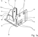
- Figure 1a is an isometric view of the connector with a view of the top according to the invention.
- the two fastening tabs 11, 11' protrude vertically upwards from the base plate 13, preferably with the two fastening tabs having an identical height above the base plate 13.
- the drill holes 12, 12 ⁇ are used for fixing to the post profile 20.
- orthogonal stiffening ribs 17 are formed, which, as in Figure 2b clearly visible, are tapered by lateral bevels and facilitate insertion into the post profile 20.
- the contact surfaces are provided as insertion aids 17a, which in the form of chamfered upper ends of the stiffening ribs 17 also facilitate insertion into the post profile 20.
- a stop surface 18 is visible in this view. For a complete understanding, please refer to the Figure 2c where all stop surfaces are shown.
- a positioning tab 19' is formed on one side of the vertical fastening tab 11, which, when mounted, lies flush with the contour in the drainage channel of the post profile and serves as a lateral support for the post profile 20.
- a material reduction 19a can be seen, which is supported laterally on the rear wall of the glazing bead groove 25.
- the connector 10 has at least one opening 14 in the fastening tab 11, which is designed like a pocket hole opening and opens into a screw channel 15, in particular a stepped one, at an angle ⁇ in the connector.
- a material accumulation 14a is formed on the inside of the fastening tab 11, which surrounds the continuing screw channel as a wall, in particular which runs at an angle ( ⁇ ) between 10 and 30°, preferably between 10 and 20° to the glass rebate plane 24 of the post or to the fastening tab 11 and is designed as a tunnel-, tube- or channel-shaped geometry.
- the mouth opening 14 serves as an entry hole for a fastening screw, which is guided at an angle ( ⁇ ) in the material accumulation 14a and exits through the screw channel 15 from the base plate 13 or the positioning pin arranged below it.
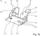
- Figure 1b shows an isometric view of the connector 10 looking towards the bottom.
- the molded positioning pin 16 offers the fastening screw (not shown) a longer guide path. When mounted, the positioning pin 16 protrudes into the adjacent glass support profile 40. The aim of a secure screw connection in the adjacent component (not shown) is achieved without the screw "running out”.
- the positioning pin forms an extension of the material accumulation and the screw channel 15 formed therein, which extends through the base plate.
- the connector 10 has a fitting area 16' on the positioning pin 16, adjacent to the base plate 13, which in particular has parallel side surfaces and is ring-shaped, in particular cylindrical.
- the fitting area 16' of the positioning pin 16 engages, preferably complementarily, in the positioning hole of the adjacent component (not shown), e.g. in the glass receiving profile 40.
- the connector 10 is also provided with at least one drill hole 15' in its base plate 13 in order to be firmly connected to the threshold using a fastening means arranged orthogonally to the threshold.
- the fastening means used are, for example, commercially available screws that are inserted into the threshold from above. (not shown)
- the connector 10 is provided with an additional 15" drill hole.
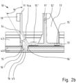
- Figure 2a shows the front view of the connector 10 with the section line A - A.
- the connector 10 is positioned in the glass rebate 42 of the glass receiving profile 40.
- the mouth openings 14, the screw channel and the material accumulation 14a are shown in this view.
- the small gap in the glass rebate is the tightening air in the dismantled state.
- the drill holes 12, 12' for fastening the connector 10 to the post profile 20 are ideally arranged at the upper edge of the vertical fastening tab 11 in order to ensure the greatest possible static stability to the post profile 20.
- Figure 2b shows the sectional view according to the section line A - A of Figure 2a . Visible are the clamping jaw-like, vertical fastening tabs 11,11', which essentially hold the post profile 20 between themselves in the assembled state. clamp in.
- the stiffening ribs 17 additionally stabilize the connector.
- the mouth opening 14 forms the entry level of the screw channel 15, which is designed as a tunnel, tube or channel-shaped geometry. The mouth opening lies in the plane of the outward-facing surface of the fastening tab.
- the design of the screw channel 15 is shaped so that a screw as a fastening means fits through and the underside of the head comes to rest on the step of the screw channel.
- the screw channel 15 In the upper part of the screw channel 15, which faces the mouth opening, the screw channel 15 has the largest diameter in order to accommodate the screw head. At the point at which the screw head enters completely behind the visible surface of the vertical fastening tab 11, a stop for the screw head is structurally predetermined by the reduced diameter of the drill hole 15. To ensure a good fit of the screw, the transition to the smaller diameter is formed by a step / chamfer, preferably which in turn is designed to be complementary to the underside of the screw head.
- the connecting screw enters the connector 10 at the angle ⁇ , is completely enclosed by the material accumulation 14a forming the wall of the screw channel 15 and the molded positioning pin 16 serves the purpose of a guide extension for the connecting screw.
- the screw channel 15 prepared in this way speeds up assembly and ensures that the screw fits precisely. This serves to connect to the threshold profile 50 of the floor threshold and initially extends through the adjacent glass receiving profile 40 held in the threshold profile 50.
- the screw (not shown) is only partially guided in the material accumulation 14a before it leaves it through the positioning pin 16 and its lower opening.
- the support of the material accumulation 14a, which continues through the base plate into the positioning pin, is sufficient due to the overall length achieved for the screw to find its way precisely into the steel reinforcement of the threshold profile 50.
- At least one orthogonally arranged screw is inserted into the drill hole 15'. It is optimally positioned at the outer end of the base plate 13.
- the drill hole 15" can optionally be mounted for additional fixation from the underside of the threshold profile 50. Since the connector is preferably first joined to the post profile 20, the drill hole 15" would not be accessible from the glass rebate 42.
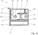
- Figure 2c shows the top view of the connector 10. All stop surfaces 18, 18 ⁇ , 18" are shown in this view.
- the connector provides these stop surfaces 18, 18 ⁇ , 18", which in the assembled state rest against corresponding stop surfaces of the post profile 20.
- the stop surfaces in the post profile can be formed, for example, by the edge surfaces of at least one notch, eg in the rebate surface.
- the desired final position is reached when the contour-milled stop surface 21 of the post profile meets the stop surfaces 18, 18', 18" of the connector.
- the stop surfaces 18, 18" are preferably at the same height level, the third stop surface 18' is at a different height level.
- the decisive factor is the analogous and corresponding arrangement of the stop surfaces 18, 18', 18" of the connector with those for contour milling of the notch 21 on the post profile 20.
- the connector 10 In the contact areas of the inner corners of connector 10 with the post profile 20, the connector 10 preferably has clearances 18a, 18a ⁇ , 18a" which are formed by a groove-shaped channel in order to enable the post profile 10 to rest unhindered in the corner areas.
- the Figure 2c shows the drill holes 15', 15", whereby the drill hole 15' is accessible from the wing profile 20 and the drill hole 15" is only accessible from the underside of the threshold profile 50.
- the screws to be arranged which are inserted into the drill holes 15 ⁇ and 15", run, seen in cross section, towards each other; they are each screwed from the outside to the opposite fastening tabs 11, 11' towards the inside of the profile.
- Figures 3a and 3b show the connector 10 to be assembled with sealing plate 70 and the adjacent profiles with a view from below and from above. The individual elements are shown in the position to be assembled.
- the post profile 20 is to be joined to the glass receiving profile 40 using the connector 10.
- the stiffening ribs 17 with the guide surfaces 17a serving as insertion aids are suitable for pushing the connector 10 into the post profile 20.
- the guide surfaces 17a which are formed by bevelled ends, for example, make it easier to insert the connector 10 into the fitting groove/Euro groove 22 on the side facing away from the glass rebate 24.
- the post profile 20 sits clamped between the stiffening ribs 17 and the vertical fastening tab 11.
- the stiffening ribs 17 are formed in pairs and spaced apart from one another such that they enclose the vertical additional fastening tab 11' between them and are firmly formed thereon.
- stiffening ribs 17 are clamped to the fitting groove 22 of the post profile 20. In the assembled state, after the screws have been tightened, this U-shaped combination of the stiffening ribs 17 with the vertical fastening tab 11' has a shape-stabilizing effect on the post profile 20.
- the connector 10 rests flat with its lower surface, which is preferably firmly connected by adhesive to an elastic sealing plate 70, in particular which at least partially corresponds to the surface of the base plate 13 and seals against moisture.
- the borehole 45 in the glass support profile 40 is one of the two positioning bores into which the positioning pins 16 engage.
- Figures 3a and 3b this shows the positioning hole 45 in the glass receiving profile.
- the screw placed in the positioning hole 45 connects the connector 10 to the threshold profile 50.
- Figure 4 shows the assembled state of the connector between the post profile 20 and the glass receiving profile 40 with a view of the glass rebate 24 and 42.
- the connector 10 fits precisely in the corner area of the post profile 20 and the glass receiving profile 40.
- the connector 10 rests in the groove of the glass rebate 42 and 24 on the rear wall of the glazing bead groove 25. Part of the mouth opening 14 can be seen.
- the screw mounted there protrudes through the glass receiving profile 40 into the steel reinforcement of the threshold profile 50.
- Figure 5a shows the assembled state of the connector 10 in its final state with the threshold profile 50 and cover profile 30.
- the wing overlap 26 of the post profile 20 and the overlap 43 of the glass receiving profile 40 form the enclosing boundaries of the glass element (not shown).
- the height of the overlap 43 in this embodiment is low, even significantly less than the depth of the wing overlap 26 of the post profile 20.
- the task of a connector 10 that takes up little space, especially in the glass rebate 42 of the glass receiving profile 40, was solved by not having any space-taking tabs protrude into this glass rebate 42.
- the glass rebate 42 is fully available to the glass recess and enables a firm fixation.
- the cover profile 30 is clipped onto the post profile 20, which provides an attractive appearance and offers additional protection against the effects of the weather.
- Figure 5b shows the assembled state of the connector 10 in its final state with the threshold without cover profile 30.
Landscapes
- Engineering & Computer Science (AREA)
- Civil Engineering (AREA)
- Structural Engineering (AREA)
- Securing Of Glass Panes Or The Like (AREA)
- Joining Of Corner Units Of Frames Or Wings (AREA)
- Connection Of Plates (AREA)
Applications Claiming Priority (1)
| Application Number | Priority Date | Filing Date | Title |
|---|---|---|---|
| DE102021134561.8A DE102021134561A1 (de) | 2021-12-23 | 2021-12-23 | Verbinder, Stoßverbindung und Verfahren zu deren Herstellung |
Publications (3)
| Publication Number | Publication Date |
|---|---|
| EP4202170A1 EP4202170A1 (de) | 2023-06-28 |
| EP4202170C0 EP4202170C0 (de) | 2024-07-24 |
| EP4202170B1 true EP4202170B1 (de) | 2024-07-24 |
Family
ID=84537105
Family Applications (1)
| Application Number | Title | Priority Date | Filing Date |
|---|---|---|---|
| EP22213873.7A Active EP4202170B1 (de) | 2021-12-23 | 2022-12-15 | Verbinder, stossverbindung und verfahren zu deren herstellung |
Country Status (3)
| Country | Link |
|---|---|
| EP (1) | EP4202170B1 (pl) |
| DE (1) | DE102021134561A1 (pl) |
| PL (1) | PL4202170T3 (pl) |
Family Cites Families (6)
| Publication number | Priority date | Publication date | Assignee | Title |
|---|---|---|---|---|
| FR2634837B1 (fr) | 1988-07-27 | 1990-10-26 | Technal Snc | Piece de jonction entre deux profiles metalliques |
| DE19904695A1 (de) * | 1998-02-05 | 1999-08-26 | Veka Ag | Kämpferverbinder |
| DE102010062751A1 (de) * | 2010-12-09 | 2012-06-14 | Greiner Tool.Tec Gmbh | Eckverbindungsvorrichtung für Profile |
| GB2511163B (en) | 2012-12-06 | 2015-07-29 | Grouphomesafe Ltd | Corner clamping system and method |
| DE202018100257U1 (de) | 2018-01-17 | 2018-06-29 | Veka Ag | Verbinderset zur Verbindung einer Bodenschwelle mit einem Blendrahmen eines Fensters oder einer Tür |
| EP3839189A1 (en) * | 2019-12-19 | 2021-06-23 | Deceuninck NV | Connection piece for connecting a post with a frame member and window or door frame comprising such connection piece |
-
2021
- 2021-12-23 DE DE102021134561.8A patent/DE102021134561A1/de active Pending
-
2022
- 2022-12-15 PL PL22213873.7T patent/PL4202170T3/pl unknown
- 2022-12-15 EP EP22213873.7A patent/EP4202170B1/de active Active
Also Published As
| Publication number | Publication date |
|---|---|
| EP4202170C0 (de) | 2024-07-24 |
| DE102021134561A1 (de) | 2023-06-29 |
| EP4202170A1 (de) | 2023-06-28 |
| PL4202170T3 (pl) | 2024-11-25 |
Similar Documents
| Publication | Publication Date | Title |
|---|---|---|
| DE102009012438B4 (de) | Pfostenverbinder | |
| DE19501101A1 (de) | Aus Profilstäben gebildete, miteinander verbundene Pfosten und Riegel | |
| EP2045431A2 (de) | Außenverkleidung mit integrierter Wärmedämmung | |
| DE4338181C2 (de) | Kunststoff-Hohlprofil | |
| EP0844348B1 (de) | Band für Türen oder Fenster | |
| EP4202170B1 (de) | Verbinder, stossverbindung und verfahren zu deren herstellung | |
| DE29620153U1 (de) | Verbindung für winklig aneinanderstoßende Hohlprofilstäbe | |
| EP1726764B1 (de) | Profil und Verfahren zu dessen Herstellung | |
| EP0725202B1 (de) | Bewehrung an Türen oder Fenstern | |
| DE29704349U1 (de) | Hohlprofil, insbesondere aus Kunststoff, zur Bildung eines Abdeckrahmens zur Verkleidung von Holzrahmen | |
| DE60130085T2 (de) | Kunststoffflügel, sowie sein Herstellungsverfahren und zweiflügelige Öffnung, z.B. für ein Fenster | |
| EP2339095B1 (de) | Tür, insbesondere Kunstofftür, mit einer Schlosskastensicherung | |
| DE20100618U1 (de) | Rahmenprofil | |
| EP3626927B1 (de) | Verbundprofil für fenster und/oder türen | |
| DE102020006840A1 (de) | Fenster- oder Türrahmen mit verschiebbaren Klemmleisten und aufgebrachter Dichtschicht | |
| DE3509187A1 (de) | Glasfluegel fuer fenster, tueren, insbesondere schiebetueren | |
| DE3609992C2 (de) | Türzarge zur Ummantelung von Metallzargen | |
| EP3715576A1 (de) | Universeller schwellenverbinder mit wechselelement | |
| DE9414631U1 (de) | Kunststoff-Hohlprofil | |
| DE9321396U1 (de) | Kunststoff-Hohlprofil | |
| EP4345240B1 (de) | Leichtmetallprofilverbindung | |
| EP0115554A1 (de) | Einrichtung zur Verkleidung eines Türstockes | |
| EP4086417B1 (de) | Schiene für eine schiebetür und montageverfahren | |
| EP4575119B1 (de) | T-verbindung und verfahren zur montage einer t-verbindung | |
| DE2607779A1 (de) | Verfahren zum einsetzen von vorgefertigten metallblendrahmen in vorhandene holzblendrahmen und vorrichtung zur durchfuehrung dieses verfahrens |
Legal Events
| Date | Code | Title | Description |
|---|---|---|---|
| PUAI | Public reference made under article 153(3) epc to a published international application that has entered the european phase |
Free format text: ORIGINAL CODE: 0009012 |
|
| STAA | Information on the status of an ep patent application or granted ep patent |
Free format text: STATUS: THE APPLICATION HAS BEEN PUBLISHED |
|
| AK | Designated contracting states |
Kind code of ref document: A1 Designated state(s): AL AT BE BG CH CY CZ DE DK EE ES FI FR GB GR HR HU IE IS IT LI LT LU LV MC ME MK MT NL NO PL PT RO RS SE SI SK SM TR |
|
| STAA | Information on the status of an ep patent application or granted ep patent |
Free format text: STATUS: REQUEST FOR EXAMINATION WAS MADE |
|
| 17P | Request for examination filed |
Effective date: 20231219 |
|
| RBV | Designated contracting states (corrected) |
Designated state(s): AL AT BE BG CH CY CZ DE DK EE ES FI FR GB GR HR HU IE IS IT LI LT LU LV MC ME MK MT NL NO PL PT RO RS SE SI SK SM TR |
|
| GRAP | Despatch of communication of intention to grant a patent |
Free format text: ORIGINAL CODE: EPIDOSNIGR1 |
|
| STAA | Information on the status of an ep patent application or granted ep patent |
Free format text: STATUS: GRANT OF PATENT IS INTENDED |
|
| INTG | Intention to grant announced |
Effective date: 20240318 |
|
| GRAS | Grant fee paid |
Free format text: ORIGINAL CODE: EPIDOSNIGR3 |
|
| GRAA | (expected) grant |
Free format text: ORIGINAL CODE: 0009210 |
|
| STAA | Information on the status of an ep patent application or granted ep patent |
Free format text: STATUS: THE PATENT HAS BEEN GRANTED |
|
| AK | Designated contracting states |
Kind code of ref document: B1 Designated state(s): AL AT BE BG CH CY CZ DE DK EE ES FI FR GB GR HR HU IE IS IT LI LT LU LV MC ME MK MT NL NO PL PT RO RS SE SI SK SM TR |
|
| REG | Reference to a national code |
Ref country code: GB Ref legal event code: FG4D Free format text: NOT ENGLISH |
|
| REG | Reference to a national code |
Ref country code: CH Ref legal event code: EP |
|
| REG | Reference to a national code |
Ref country code: IE Ref legal event code: FG4D Free format text: LANGUAGE OF EP DOCUMENT: GERMAN Ref country code: DE Ref legal event code: R096 Ref document number: 502022001306 Country of ref document: DE |
|
| U01 | Request for unitary effect filed |
Effective date: 20240809 |
|
| U07 | Unitary effect registered |
Designated state(s): AT BE BG DE DK EE FI FR IT LT LU LV MT NL PT SE SI Effective date: 20240826 |
|
| PG25 | Lapsed in a contracting state [announced via postgrant information from national office to epo] |
Ref country code: NO Free format text: LAPSE BECAUSE OF FAILURE TO SUBMIT A TRANSLATION OF THE DESCRIPTION OR TO PAY THE FEE WITHIN THE PRESCRIBED TIME-LIMIT Effective date: 20241024 |
|
| PG25 | Lapsed in a contracting state [announced via postgrant information from national office to epo] |
Ref country code: GR Free format text: LAPSE BECAUSE OF FAILURE TO SUBMIT A TRANSLATION OF THE DESCRIPTION OR TO PAY THE FEE WITHIN THE PRESCRIBED TIME-LIMIT Effective date: 20241025 |
|
| U20 | Renewal fee for the european patent with unitary effect paid |
Year of fee payment: 3 Effective date: 20241219 |
|
| PG25 | Lapsed in a contracting state [announced via postgrant information from national office to epo] |
Ref country code: IS Free format text: LAPSE BECAUSE OF FAILURE TO SUBMIT A TRANSLATION OF THE DESCRIPTION OR TO PAY THE FEE WITHIN THE PRESCRIBED TIME-LIMIT Effective date: 20241124 |
|
| PG25 | Lapsed in a contracting state [announced via postgrant information from national office to epo] |
Ref country code: HR Free format text: LAPSE BECAUSE OF FAILURE TO SUBMIT A TRANSLATION OF THE DESCRIPTION OR TO PAY THE FEE WITHIN THE PRESCRIBED TIME-LIMIT Effective date: 20240724 |
|
| PG25 | Lapsed in a contracting state [announced via postgrant information from national office to epo] |
Ref country code: RS Free format text: LAPSE BECAUSE OF FAILURE TO SUBMIT A TRANSLATION OF THE DESCRIPTION OR TO PAY THE FEE WITHIN THE PRESCRIBED TIME-LIMIT Effective date: 20241024 Ref country code: ES Free format text: LAPSE BECAUSE OF FAILURE TO SUBMIT A TRANSLATION OF THE DESCRIPTION OR TO PAY THE FEE WITHIN THE PRESCRIBED TIME-LIMIT Effective date: 20240724 |
|
| U1N | Appointed representative for the unitary patent procedure changed after the registration of the unitary effect |
Representative=s name: COHAUSZ HANNIG BORKOWSKI WISSGOTT; DE |
|
| PG25 | Lapsed in a contracting state [announced via postgrant information from national office to epo] |
Ref country code: RS Free format text: LAPSE BECAUSE OF FAILURE TO SUBMIT A TRANSLATION OF THE DESCRIPTION OR TO PAY THE FEE WITHIN THE PRESCRIBED TIME-LIMIT Effective date: 20241024 Ref country code: NO Free format text: LAPSE BECAUSE OF FAILURE TO SUBMIT A TRANSLATION OF THE DESCRIPTION OR TO PAY THE FEE WITHIN THE PRESCRIBED TIME-LIMIT Effective date: 20241024 Ref country code: IS Free format text: LAPSE BECAUSE OF FAILURE TO SUBMIT A TRANSLATION OF THE DESCRIPTION OR TO PAY THE FEE WITHIN THE PRESCRIBED TIME-LIMIT Effective date: 20241124 Ref country code: HR Free format text: LAPSE BECAUSE OF FAILURE TO SUBMIT A TRANSLATION OF THE DESCRIPTION OR TO PAY THE FEE WITHIN THE PRESCRIBED TIME-LIMIT Effective date: 20240724 Ref country code: GR Free format text: LAPSE BECAUSE OF FAILURE TO SUBMIT A TRANSLATION OF THE DESCRIPTION OR TO PAY THE FEE WITHIN THE PRESCRIBED TIME-LIMIT Effective date: 20241025 Ref country code: ES Free format text: LAPSE BECAUSE OF FAILURE TO SUBMIT A TRANSLATION OF THE DESCRIPTION OR TO PAY THE FEE WITHIN THE PRESCRIBED TIME-LIMIT Effective date: 20240724 |
|
| PG25 | Lapsed in a contracting state [announced via postgrant information from national office to epo] |
Ref country code: SM Free format text: LAPSE BECAUSE OF FAILURE TO SUBMIT A TRANSLATION OF THE DESCRIPTION OR TO PAY THE FEE WITHIN THE PRESCRIBED TIME-LIMIT Effective date: 20240724 Ref country code: RO Free format text: LAPSE BECAUSE OF FAILURE TO SUBMIT A TRANSLATION OF THE DESCRIPTION OR TO PAY THE FEE WITHIN THE PRESCRIBED TIME-LIMIT Effective date: 20240724 |
|
| PG25 | Lapsed in a contracting state [announced via postgrant information from national office to epo] |
Ref country code: CZ Free format text: LAPSE BECAUSE OF FAILURE TO SUBMIT A TRANSLATION OF THE DESCRIPTION OR TO PAY THE FEE WITHIN THE PRESCRIBED TIME-LIMIT Effective date: 20240724 |
|
| PG25 | Lapsed in a contracting state [announced via postgrant information from national office to epo] |
Ref country code: SK Free format text: LAPSE BECAUSE OF FAILURE TO SUBMIT A TRANSLATION OF THE DESCRIPTION OR TO PAY THE FEE WITHIN THE PRESCRIBED TIME-LIMIT Effective date: 20240724 |
|
| PLBE | No opposition filed within time limit |
Free format text: ORIGINAL CODE: 0009261 |
|
| STAA | Information on the status of an ep patent application or granted ep patent |
Free format text: STATUS: NO OPPOSITION FILED WITHIN TIME LIMIT |
|
| 26N | No opposition filed |
Effective date: 20250425 |
|
| PG25 | Lapsed in a contracting state [announced via postgrant information from national office to epo] |
Ref country code: MC Free format text: LAPSE BECAUSE OF FAILURE TO SUBMIT A TRANSLATION OF THE DESCRIPTION OR TO PAY THE FEE WITHIN THE PRESCRIBED TIME-LIMIT Effective date: 20240724 |
|
| PG25 | Lapsed in a contracting state [announced via postgrant information from national office to epo] |
Ref country code: IE Free format text: LAPSE BECAUSE OF NON-PAYMENT OF DUE FEES Effective date: 20241215 |
|
| REG | Reference to a national code |
Ref country code: CH Ref legal event code: U11 Free format text: ST27 STATUS EVENT CODE: U-0-0-U10-U11 (AS PROVIDED BY THE NATIONAL OFFICE) Effective date: 20260101 |
|
| PGFP | Annual fee paid to national office [announced via postgrant information from national office to epo] |
Ref country code: PL Payment date: 20251202 Year of fee payment: 4 |
|
| U20 | Renewal fee for the european patent with unitary effect paid |
Year of fee payment: 4 Effective date: 20251222 |
|
| PGFP | Annual fee paid to national office [announced via postgrant information from national office to epo] |
Ref country code: CH Payment date: 20260101 Year of fee payment: 4 |