EP4201708B1 - Reifen - Google Patents
Reifen Download PDFInfo
- Publication number
- EP4201708B1 EP4201708B1 EP22196953.8A EP22196953A EP4201708B1 EP 4201708 B1 EP4201708 B1 EP 4201708B1 EP 22196953 A EP22196953 A EP 22196953A EP 4201708 B1 EP4201708 B1 EP 4201708B1
- Authority
- EP
- European Patent Office
- Prior art keywords
- shoulder
- tire
- tie
- bar
- groove
- Prior art date
- Legal status (The legal status is an assumption and is not a legal conclusion. Google has not performed a legal analysis and makes no representation as to the accuracy of the status listed.)
- Active
Links
Images


Classifications
-
- B—PERFORMING OPERATIONS; TRANSPORTING
- B60—VEHICLES IN GENERAL
- B60C—VEHICLE TYRES; TYRE INFLATION; TYRE CHANGING; CONNECTING VALVES TO INFLATABLE ELASTIC BODIES IN GENERAL; DEVICES OR ARRANGEMENTS RELATED TO TYRES
- B60C11/00—Tyre tread bands; Tread patterns; Anti-skid inserts
- B60C11/01—Shape of the shoulders between tread and sidewall, e.g. rounded, stepped or cantilevered
-
- B—PERFORMING OPERATIONS; TRANSPORTING
- B60—VEHICLES IN GENERAL
- B60C—VEHICLE TYRES; TYRE INFLATION; TYRE CHANGING; CONNECTING VALVES TO INFLATABLE ELASTIC BODIES IN GENERAL; DEVICES OR ARRANGEMENTS RELATED TO TYRES
- B60C11/00—Tyre tread bands; Tread patterns; Anti-skid inserts
- B60C11/03—Tread patterns
- B60C11/0306—Patterns comprising block rows or discontinuous ribs
-
- B—PERFORMING OPERATIONS; TRANSPORTING
- B60—VEHICLES IN GENERAL
- B60C—VEHICLE TYRES; TYRE INFLATION; TYRE CHANGING; CONNECTING VALVES TO INFLATABLE ELASTIC BODIES IN GENERAL; DEVICES OR ARRANGEMENTS RELATED TO TYRES
- B60C11/00—Tyre tread bands; Tread patterns; Anti-skid inserts
- B60C11/03—Tread patterns
- B60C11/12—Tread patterns characterised by the use of narrow slits or incisions, e.g. sipes
- B60C11/1236—Tread patterns characterised by the use of narrow slits or incisions, e.g. sipes with special arrangements in the tread pattern
-
- B—PERFORMING OPERATIONS; TRANSPORTING
- B60—VEHICLES IN GENERAL
- B60C—VEHICLE TYRES; TYRE INFLATION; TYRE CHANGING; CONNECTING VALVES TO INFLATABLE ELASTIC BODIES IN GENERAL; DEVICES OR ARRANGEMENTS RELATED TO TYRES
- B60C11/00—Tyre tread bands; Tread patterns; Anti-skid inserts
- B60C11/03—Tread patterns
- B60C11/13—Tread patterns characterised by the groove cross-section, e.g. for buttressing or preventing stone-trapping
- B60C11/1369—Tie bars for linking block elements and bridging the groove
-
- B—PERFORMING OPERATIONS; TRANSPORTING
- B60—VEHICLES IN GENERAL
- B60C—VEHICLE TYRES; TYRE INFLATION; TYRE CHANGING; CONNECTING VALVES TO INFLATABLE ELASTIC BODIES IN GENERAL; DEVICES OR ARRANGEMENTS RELATED TO TYRES
- B60C11/00—Tyre tread bands; Tread patterns; Anti-skid inserts
- B60C11/03—Tread patterns
- B60C2011/0337—Tread patterns characterised by particular design features of the pattern
- B60C2011/0339—Grooves
- B60C2011/0341—Circumferential grooves
-
- B—PERFORMING OPERATIONS; TRANSPORTING
- B60—VEHICLES IN GENERAL
- B60C—VEHICLE TYRES; TYRE INFLATION; TYRE CHANGING; CONNECTING VALVES TO INFLATABLE ELASTIC BODIES IN GENERAL; DEVICES OR ARRANGEMENTS RELATED TO TYRES
- B60C11/00—Tyre tread bands; Tread patterns; Anti-skid inserts
- B60C11/03—Tread patterns
- B60C2011/0337—Tread patterns characterised by particular design features of the pattern
- B60C2011/0339—Grooves
- B60C2011/0358—Lateral grooves, i.e. having an angle of 45 to 90 degees to the equatorial plane
-
- B—PERFORMING OPERATIONS; TRANSPORTING
- B60—VEHICLES IN GENERAL
- B60C—VEHICLE TYRES; TYRE INFLATION; TYRE CHANGING; CONNECTING VALVES TO INFLATABLE ELASTIC BODIES IN GENERAL; DEVICES OR ARRANGEMENTS RELATED TO TYRES
- B60C11/00—Tyre tread bands; Tread patterns; Anti-skid inserts
- B60C11/03—Tread patterns
- B60C2011/0337—Tread patterns characterised by particular design features of the pattern
- B60C2011/0386—Continuous ribs
- B60C2011/0388—Continuous ribs provided at the equatorial plane
-
- B—PERFORMING OPERATIONS; TRANSPORTING
- B60—VEHICLES IN GENERAL
- B60C—VEHICLE TYRES; TYRE INFLATION; TYRE CHANGING; CONNECTING VALVES TO INFLATABLE ELASTIC BODIES IN GENERAL; DEVICES OR ARRANGEMENTS RELATED TO TYRES
- B60C11/00—Tyre tread bands; Tread patterns; Anti-skid inserts
- B60C11/03—Tread patterns
- B60C11/12—Tread patterns characterised by the use of narrow slits or incisions, e.g. sipes
- B60C11/1204—Tread patterns characterised by the use of narrow slits or incisions, e.g. sipes with special shape of the sipe
- B60C2011/1209—Tread patterns characterised by the use of narrow slits or incisions, e.g. sipes with special shape of the sipe straight at the tread surface
-
- Y—GENERAL TAGGING OF NEW TECHNOLOGICAL DEVELOPMENTS; GENERAL TAGGING OF CROSS-SECTIONAL TECHNOLOGIES SPANNING OVER SEVERAL SECTIONS OF THE IPC; TECHNICAL SUBJECTS COVERED BY FORMER USPC CROSS-REFERENCE ART COLLECTIONS [XRACs] AND DIGESTS
- Y02—TECHNOLOGIES OR APPLICATIONS FOR MITIGATION OR ADAPTATION AGAINST CLIMATE CHANGE
- Y02T—CLIMATE CHANGE MITIGATION TECHNOLOGIES RELATED TO TRANSPORTATION
- Y02T10/00—Road transport of goods or passengers
- Y02T10/80—Technologies aiming to reduce greenhouse gasses emissions common to all road transportation technologies
- Y02T10/86—Optimisation of rolling resistance, e.g. weight reduction
Definitions
- the present invention relates to a tire.
- JP 2015-137015 A discloses a pneumatic tire in which shoulder blocks are specifically designed to prevent the vehicle from overturning when turning.
- the loss tangent and the lateral rigidity of the shoulder blocks are adjusted in order to reduce the cornering force by the shoulder blocks when the vehicle rolls largely, thereby preventing the overturning.
- EP 2 591 923 A2 discloses a tire according to the preamble of claim 1.
- other related tires are disclosed in EP 3 375 635 A1 , EP 2 610 081 A2 , EP 2 465 706 A2 , JP 2011-084254 A , and JP 2018-090230 A .
- the present invention was made in view of the above circumstances, and a primary objective of the present invention is to provide a tire in which the resistance to vehicle overturning can be effectively improved, while maintaining wear resistance of shoulder blocks.
- the present invention is defined by a tire having the features of claim 1.
- the tire can exhibit excellent resistance to vehicle overturning while maintaining the wear resistance of the shoulder blocks.
- the present invention is suitably applied to pneumatic tires for passenger cars, but the present invention may be applied to pneumatic tires for heavy duty vehicles such as trucks and buses, as well as non-pneumatic tires so called airless tire.
- FIG. 1 is a developed partial view of the tread portion 2 of a tire 1 as an embodiment of the present invention.
- the tire 1 comprises a tread portion 2 having a first tread edge T1 and a second tread edge T2.
- the tread portion 2 is provided with circumferential grooves 3 disposed between the first tread edge T1 and the second tread edge T2 and extending continuously in the tire circumferential direction.
- the tread portion 2 comprises land portions 4 axially divided by the circumferential grooves 3.
- the tread portion 2 is provided with four circumferential grooves 3, and thereby, divided into five land portions 4 as shown in FIG. 1 .
- the tread portion 2 may be divided into four land portions 4 by three circumferential grooves 3.
- the tire 1 is bidirectional, and not specified which side should be outboard when the tire is attached to a vehicle.
- first tread edge T1 is shown as the tread edge on the left side of the tire equator C
- second tread edge T2 is shown as the tread edge on the right side of the tire equator C.
- a half of the tread portion 2 between the first tread edge T1 and the tire equator C has substantially the same configuration as a half of the tread portion 2 between the second tread edge T2 and the tire equator C.
- the tread portion 2 has a point-symmetrical tread pattern.
- the first tread edge T1 and the second tread edge T2 correspond to the axially outermost edges of the ground contacting patch of the tire 1 when the tire 1 under its normal state is loaded by a normal load and the tread portion 2 is contacted with a flat horizontal surface at a camber angle of 0 degrees.
- the "normal state” means a state of the tire which is mounted on a normal rim and inflated to a normal pressure, but loaded with no tire load.
- the "normal state” means a standard usage state according to the purpose of use of the tire, which is not mounted on the vehicle and loaded with no load.
- the normal rim is a wheel rim officially approved or recommended for the tire by standards organizations, i.e. JATMA (Japan and Asia), T&RA (North America), ETRTO (Europe), TRAA (Australia), STRO (Scandinavia), ALAPA (Latin America), ITTAC (India) and the like which are effective in the area where the tire is manufactured, sold or used.
- the normal pressure is the air pressure officially approved or recommended for the tire by standards organizations, i.e. JATMA (Japan and Asia), T&RA (North America), ETRTO (Europe), TRAA (Australia), STRO (Scandinavia), ALAPA (Latin America), ITTAC (India) and the like which are effective in the area where the tire is manufactured, sold or used.
- the "normal load” is a load specified for the tire by a standard included in a standardization system on which the tire is based, for example, the "maximum load capacity" in JATMA, maximum value listed in “TIRE LOAD LIMITS AT VARIOUS COLD INFLATION PRESSURES" table in TRA, and "LOAD CAPACITY" in ETRTO.
- the "normal load” refers to the maximum load applicable to the tire.
- the circumferential grooves 3 include two shoulder circumferential grooves 5 and two crown circumferential grooves 6.
- the two shoulder circumferential grooves 5 are disposed adjacently to the first tread edge T1 and second tread edge T2, respectively.
- each of the circumferential grooves 3 is a straight groove extending in parallel with the tire circumferential direction.
- the groove width w1 of each of the circumferential grooves 3 is at least 3 mm.
- the groove width w1 of each of the circumferential grooves 3 is set in a range from 3.0% to 5.0% of the tread width TW.
- the tread width TW is the distance in the tire axial direction between the first tread edge T1 and the second tread edge T2 in the normal state.
- the land portions 4 include two shoulder land portions 7.
- the two shoulder land portions 7 comprise the first tread edge T1 and the second tread edge T2, respectively, and are defined on the axially outside of the respective shoulder circumferential grooves 5.
- the two shoulder land portions 7 have substantially the same configuration.
- the land portions 4 further include two middle land portions 8 and one crown land portion 9.
- the two middle land portions 8 are positioned adjacently to the respective shoulder land portions 7 via the shoulder circumferential grooves 5.
- the two middle land portions 8 are respectively defined between the crown circumferential groove 6 and the respective shoulder circumferential grooves 5.
- the two middle land portions 8 have substantially the same configuration.
- the crown land portion 9 is defined between the two crown circumferential grooves 6 and positioned on the tire equator C.
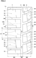
- FIG. 2 shows the shoulder land portion 7 and the middle land portion 8 which are disposed on the first tread edge T1 side of the tire equator C.
- the shoulder land portion 7 is provided with lateral grooves 12 extending from the shoulder circumferential groove 5 to the first tread edge T1.
- the shoulder land portion 7 is circumferentially divided into shoulder blocks 10 by the shoulder lateral grooves 12.
- the width w2 in the tire axial direction of the ground contacting top surface of each of the shoulder blocks 10 is set in a range from 35% to 48% of a half tread width TWh.
- the half tread width TWh is the distance in the tire axial direction from the tire equator C to the first tread edge T1 under the normal state of the tire, and corresponds to a half of the above-mentioned tread width TW.
- FIG. 3 shows three of the shoulder lateral grooves 12 and two of the shoulder blocks 10.
- each of the shoulder blocks 10 is provided with one or more shoulder sipes 15 extending in the tire circumferential direction.
- swipe means an incision having a small width and having two opposite side walls, the two opposite side walls extend substantially parallel to each other, and the width w2 between the two opposite side walls is 2.0 mm or less.
- the expression “substantially parallel” means that the angle between the two opposite side walls is 10 degrees or less.
- the width W2 of the sipe is 0.5 to 1.5 mm, more preferably 0.5 to 1.0 mm.
- the width w2 of the sipe is constant from the opening to the bottom thereof.
- the present invention is not limited to such constant width.
- the width of the sipe may be increased near the open top of the sipe by providing a chamfer for the sipe edge or edges.
- the width of the sipe may be increased near the bottom of the sipe so as to have a flask-shaped cross sectional shape.
- the expression "the shoulder sipe 15 extending in the tire circumferential direction” means that the maximum angle of the center line of the shoulder sipe 15 with respect to the tire circumferential direction is not more than 30 degrees in its top view.
- the expression "the ground contacting top surface of each of the shoulder blocks 10 is provided with one or more shoulder sipes 15" means that the ground contacting top surface of each of the shoulder blocks 10 is not provided with a locally depressed portion such as groove, sipe and recess, except for the shoulder sipe or sipes 15.
- the tire 1 according to the present invention by adopting the above configuration, it is possible to exhibit excellent resistance to vehicle overturning while maintaining the wear resistance of the shoulder blocks 10.
- the mechanism is as follows.
- the axial width W2 of the ground contacting top surface of each of the shoulder blocks 10 is in a range from 35% to 48% of the half tread width TWh, the rigidity of the shoulder blocks 10 is optimized. As a result, it is possible to improve the resistance to vehicle overturning while maintaining the wear resistance of the shoulder blocks 10.
- each of the shoulder blocks 10 is provided with one or more shoulder sipes 15 extending in the tire circumferential direction, the rigidity in the tire axial direction of the shoulder blocks 10 is reduced, and thereby the resistance to vehicle overturning is improved.
- the rigidity in the tire circumferential direction of the shoulder blocks 10 is not reduced by the shoulder sipes 15 and is maintained, so the wear resistance of the shoulder blocks 10 can be maintained.
- the resistance to vehicle overturning can be improved while maintaining the wear resistance of the shoulder blocks 10.
- the width w2 (shown in FIG. 2 ) in the tire axial direction of the ground contacting top surface of each of the shoulder blocks 10 is set in a range from 40% to 45% of the half tread width TWh.
- each of the shoulder blocks 10 is smaller than the width W2 in the tire axial direction of the ground contacting top surface.
- the length L4 is in a range from 60% to 75% of the width w2.
- the ground contacting top surface of the shoulder block 10 is long in the tire axial direction.
- the ground contacting top surface has a rectangular shape.
- the shoulder lateral grooves 12 in this example are arranged at an angle of not more than 30 degrees, preferable not more than 20 degrees, more preferably not more than 10 degrees with respect to the tire axial direction.
- the shoulder lateral grooves 12 extend parallel with the tire axial direction. Thereby, wear of the shoulder block 10 is suppressed.
- the shoulder lateral groove 12 extends in the tire axial direction with a constant groove width from the shoulder circumferential groove 5 to the first tread edge T1.
- the groove width w4 of the shoulder lateral groove 12 is smaller than the groove width w3 of the shoulder circumferential groove 5.
- the groove width w4 of the shoulder lateral groove 12 is in a range from 85% to 95% of the groove width W3 of the shoulder circumferential groove 5.
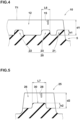
- FIG. 4 shows a cross-sectional view taken along line A-A of FIG. 2 .
- the shoulder lateral grooves 12 include a tie-bar-equipped shoulder lateral groove 12 which is, as shown in FIG. 4 , provided with tie bars 20 raising from the groove bottom so as to connect between two of the shoulder blocks 10 adjacent to each other through the tie-bar-equipped shoulder lateral groove 12.
- tie bars 20 can further improve the wear resistance.
- the tie bars 20 are omitted from the shoulder lateral grooves 12 for the sake of simplicity.
- the tie bars 20 include an axially inner tie bar 21, an axially outer tie bar 22 and an intermediate tie bar 23.
- the axially inner tie bar 21 is disposed axially inside a center position in the tire axial direction of the tie-bar-equipped shoulder lateral groove 12, wherein the center position is that of the center between the axially inner end at the shoulder circumferential groove 5 and the axially outer end at the first tread edge.
- the axially inner tie bar 21 is disposed at the axially inner end of the tie-bar-equipped shoulder lateral groove 12.
- Such inner tie bar 21 serves for suppressing uneven wear occurring near the axially inner end portion of the tie-bar-equipped shoulder lateral groove 12.
- the axially outer tie bar 22 is disposed axially outside the above-mentioned center position of the tie-bar-equipped shoulder lateral groove 12.
- the outer tie bar 22 is disposed at the shoulder lateral groove's axially outer end at the first tread edge.
- the first tread edge T1 is included in this zone.
- the first tread edge T1 is included in the extent of the radially outer surface of the outer tie bar 22 in the length direction of the tie-bar-equipped shoulder lateral groove 12.
- Such outer tie bars 22 serve for suppressing uneven wear occurring near the first tread edge T1.
- the intermediate tie bar 23 is disposed between both ends in the tire axial direction of the shoulder lateral groove 12, and between the axially outer tie bar 22 and the axially inner tie bar 21.
- the distance between the intermediate tie bar 23 and the axially inner tie bar 21 is smaller than the distance between the intermediate tie bar 23 and the axially outer tie bar 22.
- Such intermediate tie bar 23 can effectively suppress the shoulder lateral groove 12 from opening excessively, and can further improve the wear resistance.
- the shoulder lateral groove 12 in the present embodiment is provided with only the axially inner tie bar 21, axially outer tie bar 22, and intermediate tie bar 23.
- the present invention is not limited to such arrangement.
- the shoulder lateral groove 12 may be provided with only one of these tie bars 20, or only two of these tie bars 20.
- the length L6 in the tire axial direction of one tie bar 20 is, for example, set in a range from 15% to 25% of the axial width w2 of the ground contacting top surface of the shoulder block 10.
- the total axial length of all the tie bars 20 disposed in one shoulder lateral groove 12 is set in a range from 40% to 60% of the axial width W2 of the ground contacting top surface of the shoulder block 10.
- the axial length of the tie bar 20 is measured at the center position in the radial height direction of the tie bar 20.
- the axially inner tie bar 21, the axially outer tie bar 22, and the intermediate tie bar 23 have the same radial height h1.
- the radial height h1 is set in a range from 25% to 60%, more preferably 30% to 50% of the maximum depth d1 of the shoulder lateral groove 12.
- each shoulder sipe 15 extends from one of the shoulder lateral grooves 12 and ends within the shoulder block 10.
- the angle of the shoulder sipe 15 with respect to the tire circumferential direction is preferably set in a range from 5 to 15 degrees.
- the shoulder sipe 15 is connected to the shoulder lateral groove 12 at the formation position of one of the plurality of tie bars 20.
- the shoulder sipe 15 is connected to the shoulder lateral groove 12 at the forming position of the intermediate tie bar 23. Thereby, it is possible to further improve the wear resistance.
- the expression "at the formation position of the tie bar 20" means that the shoulder sipe 15 is included in a zone, which extends radially outwardly from the radially outer surface of the tie bar 20 while keeping a constant width equal to that of the radially outer surface, in the cross section of the tie-bar-equipped shoulder lateral groove 12 taken along the length direction of the groove 12.
- the boundary between the radially outer surface and the other surface of the tie bar 20 is lies at the center position of the tie bar 20 in the radial height direction.
- the above-said at least one shoulder sipe 15 includes a first shoulder sipe 16 and a second shoulder sipe 17.
- each of the shoulder blocks 10 is provided with one first shoulder sipe 16 and one second shoulder sipe 17.
- the first shoulder sipe 16 is connected to one of the tie-bar-equipped shoulder lateral grooves 12 which is positioned on one side of the shoulder block 10 in the tire circumferential direction (lower side in FIG. 3 ), and the second shoulder sipe 17 is connected to one of the tie-bar-equipped shoulder lateral grooves 12 which is positioned on the other side of the shoulder block 10 in the tire circumferential direction (upper side in FIG. 3 ).
- both the first shoulder sipe 16 and the second shoulder sipe 17 are connected to the respective tie-bar-equipped shoulder lateral grooves 12 at the respective formation positions of the intermediate tie bars 23.
- first shoulder sipe 16 and the second shoulder sipe 17 are disposed axially inside a center line 10a of the shoulder block 10 in the tire axial direction (in FIG. 3 , the center line is indicated by alternate long and short dash line).
- edges of the first shoulder sipe 16 and the edges of the second shoulder sipe 17 are completely positioned axially inside the center line 10a.
- the rigidity of the shoulder block 10 is relaxed in its axially inside region, and as a result, the ride comfort performance is further improved.
- the axial distance L3 from the connecting position 16a of the first shoulder sipe 16 with the shoulder lateral groove 12 to the axially inner end of the shoulder lateral groove 12 is preferably set in a range from 30% to 45% of the axial width w2 of the ground contacting top surface of the shoulder block 10.
- the axial distance L3 from the connecting position 17a of the second shoulder sipe 17 with the shoulder lateral groove 12 to the axially inner end of the shoulder lateral groove 12 is preferably set in a range from 30% to 45% of the axial width W2 of the ground contacting top surface of the shoulder block 10.
- the connecting position 17a of the second shoulder sipe 17 with the shoulder lateral groove 12 is displaced in the tire axial direction from the connecting position 16a of the first shoulder sipe 16 with the shoulder lateral groove 12.
- the distance L9 in the tire axial direction between the connecting position 16a and the connecting position 17a is preferably set in a range from 5% to 10% of the axial width w2 of the ground contacting top surface of the shoulder block 10. Thereby, it becomes possible to further improve the wear resistance of the shoulder blocks 10.
- first shoulder sipe 16 and the second shoulder sipe 17 are inclined in the same direction with respect to the tire circumferential direction.
- first shoulder sipe 16 and the second shoulder sipe 17 are inclined at the same angle with respect to the tire circumferential direction.
- the angle ⁇ 1 between the shoulder lateral groove 12 and the shoulder sipe 15 is set in a range from 25 to 85 degrees.
- first shoulder sipe 16 and the second shoulder sipe 17 are arranged such that the first shoulder sipe 16 and the second shoulder sipe 17 are positioned within a narrow zone 19.
- the first shoulder sipe 16 and the second shoulder sipe 17 are arranged so as to extend substantially on a straight line.
- the width of the narrow zone 19 can be the substantially same as the width of the sipes 16 and 17.
- each shoulder sipe 15 (16, 17) ends within the shoulder block 10 without crossing the center line 10b of the shoulder block 10 in the tire circumferential direction (indicated by the alternate long and short dash line in FIG. 2 ).
- the length L5 in the tire circumferential direction of the shoulder sipe 15 is set in a range from 25% to 35% of the length L4 in the tire circumferential direction of the shoulder block 10.
- Such shoulder sipes 15 serve for improving the wear resistance and the ride comfort performance in a well-balanced manner.
- Each of the middle land portions 8 is provided with middle lateral grooves 26 as shown in FIG. 2 .
- the middle lateral grooves 26 extend across the entire axial width of the middle land portion 8. Thereby, the middle land portion 8 is circumferentially divided into middle blocks 25.
- the width w5 in the tire axial direction of the ground contacting top surface of the middle block 25 is smaller than the width W2 in the tire axial direction of the ground contacting top surface of the shoulder block 10.
- the axial width w5 of the ground contacting top surface of the middle block 25 is in a range from 55% to 70% of the axial width w2 of the ground contacting top surface of the shoulder block 10.
- the middle lateral grooves 26 in the present embodiment are inclined with respect to the tire axial direction.
- the angle ⁇ 2 of the middle lateral grooves 26 with respect to the tire axial direction is larger than the angle of the shoulder lateral grooves 12 with respect to the tire axial direction.
- the angle ⁇ 2 with respect to the tire axial direction increases toward the inside in the tire axial direction, wherein, the angle ⁇ 2 is in a range from 10 to 45 degrees, for example.
- the groove width W6 of the middle lateral grooves 26 is larger than the groove width w4 of the shoulder lateral grooves 12.
- the groove width w6 of the middle lateral grooves 26 is in a range from 110% to 130% of the groove width w4 of the shoulder lateral grooves 12.
- FIG. 5 shows a cross-sectional view taken along line B-B of FIG. 2 .
- the middle lateral grooves 26 include a tie-bar-equipped middle lateral groove 28 which is, as shown in FIG. 5 , provided with at least one middle tie bar 30 raising from the groove bottom so as to connect between two of the middle blocks 25 adjacent to each other through the tie-bar-equipped middle lateral groove 28.
- each of the middle lateral grooves 26 is provided with only one middle tie bar 30.
- the middle tie bar 30 serves for increasing the rigidity of the middle land portion 8 in the tire circumferential direction and improving the wear resistance.
- only one middle tie bar 30 is disposed between both ends in the tire axial direction of the middle lateral groove 26.
- a plurality of middle tie bars 30 may be disposed in one middle lateral groove 26.
- the length L7 in the tire axial direction of the single middle tie bar 30 is, for example, set in a range from 40% to 55% of the width W5 (shown in FIG. 2 ) in the tire axial direction of the middle block 25.
- the maximum height h2 of the middle tie bar 30 is set in a range from 25% to 40% of the maximum depth d2 of the middle lateral groove 26.
- the middle tie bar 30 is disposed so as to extend across the center position in the tire axial direction of the middle lateral groove 26. Thereby, the wear resistance and the ride comfort performance are improved in a well-balanced manner.
- the axial length L7 of the middle tie bar 30 is smaller than the total axial length of the axially inner tie bar 21, the outer tie bar 22 and the intermediate tie bar 23.
- Each of the middle blocks 25 is provided with at least one middle sipe 28 as shown in FIG. 2 .
- the middle sipe 28 is connected to at least one of the two middle lateral grooves 26 located on both sides in the tire circumferential direction of the middle blocks 25.
- the middle sipe 28 is connected to the two middle lateral grooves 26 located on both sides in the tire circumferential direction. That is, the middle sipe 28 completely crosses the middle block 25 in the tire circumferential direction.
- each of the both ends in the tire circumferential direction of the middle sipe 28 is connected to a central portion of the middle lateral groove 26 when the middle lateral groove 26 is divided into three equal parts in the length direction.
- Such middle sipe 28 serves for relaxing the rigidity in the tire axial direction of the middle block 25 and improving the ride comfort performance.
- the middle sipe 28 in this example is inclined with respect to the tire circumferential direction.
- the middle sipe 28 is inclined in the same direction as the shoulder sipe 15.
- the angle ⁇ 3 between the middle sipe 28 and the middle lateral groove 26 is, for example, set in a range from 75 to 90 degrees.
- Such middle sipe 28 serves for improving the wear resistance and the ride comfort performance in a well-balanced manner.
- the number Ns of the shoulder lateral grooves 12 disposed in each shoulder land portion 7 is larger than the number Nm of the middle lateral grooves 26 disposed in each middle land portion 8.
- each shoulder block 10 can be made relatively small, and the overall wear resistance of the land portions and various dynamic performances including steering stability can be maintained while improving the resistance to vehicle overturning.
- the number Ns is not more than 110% of the number Nm. Thereby, the above-mentioned performance is improved in a well-balanced manner.
- the middle sipe 28 is connected to the middle lateral groove 26 at the same forming position as the middle tie bar 30 as shown in FIG. 5 .
- the connecting position between the middle lateral groove 26 and the middle sipe 28 is reinforced by the middle tie bar 30, and uneven wear near the connecting position is suppressed.
- each of the middle blocks 25 is not provided with a groove or a sipe except for the middle sipe 28. Thereby, the above-mentioned effect can be further enhanced.
- FIG. 6 is a top view of a part of the crown land portion 9.
- the width w7 in the tire axial direction of the crown land portion 9 is set in a range from 10% to 20% of the tread width TW (shown in FIG. 1 ).
- the width w7 of the crown land portion 9 is smaller than the width w2 in the tire axial direction of the shoulder block 10.
- the crown land portion 9 is provided with first crown lateral grooves 36 and second crown lateral grooves 37.
- the first crown lateral grooves 36 extend from the crown circumferential groove 6 on one side in the tire axial direction (left side in FIG. 6 ) of the crown land portion 9, toward the tire equator C, and ends within the crown land portion 9.
- the second crown lateral grooves 37 extend from the crown circumferential groove 6 on the other side in the tire axial direction (right side in FIG. 6 ) of the crown land portion 9, toward the tire equator C, and ends within the crown land portion 9.
- the first crown lateral grooves 36 and the second crown lateral grooves 37 can enhance the wet performance, while maintaining the rigidity of the crown land portion 9.
- the axial length L8 of the first crown lateral groove 36 and the axial length L8 of the second crown lateral groove 37 are preferably set in a range from 45% to 55% of the axial width W7 of the crown land portion 9.
- the first crown lateral grooves 36 are curved convexly toward one side in the tire circumferential direction (upper side in FIG. 6 ), whereas
- the second crown lateral grooves 37 are curved convexly toward the other side in the tire circumferential direction (lower side in FIG. 6 ). Thereby, uneven wear of the crown land portion 9 is further suppressed.
- pneumatic tires of size 235/60R17C having specifications shown in Table 1 were experimentally manufactured as test tires (working examples Ex.1-Ex.5 and comparative examples Ref.1-Ref.2), and tested for the wear resistance of the shoulder blocks and the resistance to vehicle overturning as follows.
- a test car (3000cc 4WD car) with the same test tires mounted on all wheels and inflated to 525 kPa was entered into an asphalt paved test course at a speed of 80 km/h and, with sharp steering operation, the steering wheel was rotated in one direction at a predetermined steering angle, and then immediately the steering wheel was turned in the opposite direction at the same steering angle. And it was observed whether the tires were lifted from the road surface more than 5 cm due to the roll of the vehicle body. The results are shown in Table 1. Table 1 tire Ref.
Landscapes
- Engineering & Computer Science (AREA)
- Mechanical Engineering (AREA)
- Tires In General (AREA)
Claims (7)
- Reifen (1), umfassendeinen Laufflächenabschnitt (2), der eine erste Laufflächenkante (T1) aufweist und mit einer Schulterumfangsrille (5) versehen ist, die benachbart zu der ersten Laufflächenkante (T1) angeordnet ist und sich kontinuierlich in der Reifenumfangsrichtung erstreckt, um einen Schulterlandabschnitt (7) zwischen der Schulterumfangsrille (5) und der ersten Laufflächenkante (T1) zu definieren,
wobeider Schulterlandabschnitt (7) mit Schulterquerrillen (12) versehen ist, die sich von der Schulterumfangsrille (5) zu der ersten Laufflächenkante (T1) erstrecken, um den Schulterlandabschnitt (7) in Umfangsrichtung in Schulterblöcke (10) zu unterteilen, unddie Schulterquerrillen (12) eine mit einem Anbindungssteg ausgestattete Schulterquerrille (12) umfassen, die mit mindestens einem Anbindungssteg (20) versehen ist, der sich von dem Rillenboden erhebt, um zwischen zweien der Schulterblöcke (10), die benachbart zu der mit einem Anbindungssteg ausgestatteten Schulterquerrille (12) sind, eine Verbindung herzustellen,dadurch gekennzeichnet, dass die Breite (W2) in der Reifenaxialrichtung der den Boden berührenden oberen Oberfläche jedes der Schulterblöcke (10) in einem Bereich von 35 % bis 48 % einer halben Laufflächenbreite (TWh) zwischen der ersten Laufflächenkante (T1) und dem Reifenäquator (C) liegt,jeder der Schulterblöcke (10) mit einem oder mehreren Schulterfeinschnitten (15) versehen ist, die sich jeweils von einer der Schulterquerrillen (12) erstrecken und innerhalb des Schulterblocks (10) enden,die den Boden berührende obere Oberfläche jedes der Schulterblöcke (10) mit einem oder mehreren Schulterfeinschnitten (15) versehen ist, die sich in der Reifenumfangsrichtung erstrecken,die Schulterquerrillen (12) eine mit einem Anbindungssteg ausgestattete Schulterquerrille (12) umfassen, die mit Anbindungsstegen (20) versehen ist, die sich von dem Rillenboden erheben, um zwischen zweien der Schulterblöcke (10), die über die mit einem Anbindungssteg ausgestattete Schulterquerrille (12) benachbart zueinander sind, eine Verbindung herzustellen, undin dem Fall, dass der Schulterfeinschnitt (15) mit der mit einem Anbindungssteg ausgestatteten Schulterquerrille (12) verbunden ist, der Schulterfeinschnitt (15) an einer Ausbildungsposition eines der Anbindungsstege (20) in der Reifenaxialrichtung verbunden ist. - Reifen (1) nach Anspruch 1, wobei
die Anbindungsstege (20) einen axial inneren Anbindungssteg (21) umfassen, der axial innen von der Mittelposition in der Reifenaxialrichtung der mit einem Anbindungssteg ausgestatteten Schulterquerrille (12) angeordnet ist. - Reifen (1) nach Anspruch 1 oder 2, wobei
die Anbindungsstege (20) einen axial äußeren Anbindungssteg (22) umfassen, der axial außen von der Mittelposition in der Reifenaxialrichtung der mit einem Anbindungssteg ausgestatteten Schulterquerrille (12) angeordnet ist. - Reifen (1) nach einem der Ansprüche 1 bis 3, wobei
die Anbindungsstege (20) einen Zwischenanbindungssteg (23) umfassen, der zwischen beiden Enden in der Reifenaxialrichtung der mit einem Anbindungssteg ausgestatteten Schulterquerrille (12) angeordnet ist. - Reifen (1) nach einem der Ansprüche 1 bis 4, wobeider Laufflächenabschnitt (2) einen mittleren Landabschnitt (8) umfasst, der zu dem Schulterlandabschnitt (7) durch die Schulterumfangsrille (5) benachbart ist, undder mittlere Landabschnitt (8) mit mittleren Querrillen (26) versehen ist, die den mittleren Landabschnitt (8) in der Reifenaxialrichtung vollständig kreuzen,der mittlere Landabschnitt (8) mittlere Blöcke (25) umfasst, die durch die mittleren Querrillen (26) in Umfangsrichtung unterteilt sind, unddie mittleren Querrillen (26) eine mit einem Anbindungssteg ausgestattete mittlere Querrille (28) umfassen, die mit mindestens einem mittleren Anbindungssteg (30) versehen ist, der sich von dem Rillenboden erhebt, um zwischen zweien der mittleren Blöcke (25), die durch die mit einem Anbindungssteg ausgestattete mittlere Querrille (28) benachbart zueinander sind, eine Verbindung herzustellen.
- Reifen (1) nach Anspruch 5, wobeijeder der mittleren Blöcke (25) mit einem mittleren Feinschnitt (28) versehen ist, der mit einer der mittleren Querrillen (26) verbunden ist, undin dem Fall, dass der mittlere Feinschnitt (28) mit der mit einem Anbindungssteg ausgestatteten mittleren Querrille (28) verbunden ist, der mittlere Feinschnitt (28) an einer Ausbildungsposition in der Reifenaxialrichtung nur eines mittleren Anbindungsstegs (30) oder eines der mittleren Anbindungsstege (30) verbunden ist.
- Reifen (1) nach Anspruch 5 oder 6, wobei
die Anzahl der Schulterquerrillen (12), die in dem Schulterlandabschnitt (7) angeordnet sind, größer ist als die Anzahl der mittleren Querrillen (26), die in dem mittleren Landabschnitt (8) angeordnet sind.
Applications Claiming Priority (1)
| Application Number | Priority Date | Filing Date | Title |
|---|---|---|---|
| JP2021212657A JP7767915B2 (ja) | 2021-12-27 | 2021-12-27 | タイヤ |
Publications (2)
| Publication Number | Publication Date |
|---|---|
| EP4201708A1 EP4201708A1 (de) | 2023-06-28 |
| EP4201708B1 true EP4201708B1 (de) | 2024-12-18 |
Family
ID=83400645
Family Applications (1)
| Application Number | Title | Priority Date | Filing Date |
|---|---|---|---|
| EP22196953.8A Active EP4201708B1 (de) | 2021-12-27 | 2022-09-21 | Reifen |
Country Status (4)
| Country | Link |
|---|---|
| US (1) | US12162313B2 (de) |
| EP (1) | EP4201708B1 (de) |
| JP (1) | JP7767915B2 (de) |
| CN (1) | CN116353254A (de) |
Families Citing this family (1)
| Publication number | Priority date | Publication date | Assignee | Title |
|---|---|---|---|---|
| KR102802029B1 (ko) * | 2022-09-29 | 2025-04-28 | 한국타이어앤테크놀로지 주식회사 | 소음 저감 타이어 |
Family Cites Families (20)
| Publication number | Priority date | Publication date | Assignee | Title |
|---|---|---|---|---|
| US4690189A (en) * | 1986-01-29 | 1987-09-01 | The Goodyear Tire & Rubber Company | All-season pneumatic tire with chamfered tread blocks |
| JP2834594B2 (ja) * | 1991-04-16 | 1998-12-09 | 株式会社ブリヂストン | 騒音を低減した空気入りタイヤ |
| JP3116243B2 (ja) * | 1991-12-24 | 2000-12-11 | 横浜ゴム株式会社 | 空気入りスタッドレスタイヤ |
| JP3205880B2 (ja) * | 1992-04-28 | 2001-09-04 | 東洋ゴム工業株式会社 | 空気入りタイヤ |
| IT1265035B1 (it) * | 1993-05-31 | 1996-10-28 | Pirelli | Pneumatico per ruote di veicoli con battistrada a bassa rumorosita' di rotolamento |
| DE69414692T2 (de) * | 1993-12-27 | 1999-04-08 | Hirohisha Kyoto Fukata | Fahrzeugreifen |
| JP4297236B2 (ja) * | 2000-03-30 | 2009-07-15 | 横浜ゴム株式会社 | 冬用空気入りタイヤ |
| JP2010100095A (ja) * | 2008-10-21 | 2010-05-06 | Bridgestone Corp | 空気入りタイヤ |
| JP5321093B2 (ja) * | 2009-01-26 | 2013-10-23 | 横浜ゴム株式会社 | 空気入りタイヤ |
| JP2011084254A (ja) * | 2009-10-19 | 2011-04-28 | Sumitomo Rubber Ind Ltd | 空気入りタイヤ |
| JP5149957B2 (ja) * | 2010-12-14 | 2013-02-20 | 住友ゴム工業株式会社 | 空気入りタイヤ |
| JP5438719B2 (ja) * | 2011-04-20 | 2014-03-12 | 住友ゴム工業株式会社 | 空気入りタイヤ |
| JP5503622B2 (ja) * | 2011-11-08 | 2014-05-28 | 住友ゴム工業株式会社 | 空気入りタイヤ |
| JP5385968B2 (ja) * | 2011-12-28 | 2014-01-08 | 住友ゴム工業株式会社 | 空気入りタイヤ |
| JP2015137015A (ja) * | 2014-01-22 | 2015-07-30 | 住友ゴム工業株式会社 | 空気入りタイヤ |
| JP6878960B2 (ja) * | 2016-11-28 | 2021-06-02 | 住友ゴム工業株式会社 | 空気入りタイヤ |
| JP6825434B2 (ja) * | 2017-03-16 | 2021-02-03 | 住友ゴム工業株式会社 | タイヤ |
| JP2019127069A (ja) * | 2018-01-22 | 2019-08-01 | 横浜ゴム株式会社 | 空気入りタイヤ |
| JP7314446B2 (ja) * | 2019-09-10 | 2023-07-26 | Toyo Tire株式会社 | 空気入りタイヤ |
| JP7726004B2 (ja) * | 2021-10-18 | 2025-08-20 | 住友ゴム工業株式会社 | タイヤ |
-
2021
- 2021-12-27 JP JP2021212657A patent/JP7767915B2/ja active Active
-
2022
- 2022-09-21 EP EP22196953.8A patent/EP4201708B1/de active Active
- 2022-11-03 CN CN202211370538.2A patent/CN116353254A/zh active Pending
- 2022-12-23 US US18/087,909 patent/US12162313B2/en active Active
Also Published As
| Publication number | Publication date |
|---|---|
| JP7767915B2 (ja) | 2025-11-12 |
| JP2023096718A (ja) | 2023-07-07 |
| EP4201708A1 (de) | 2023-06-28 |
| US12162313B2 (en) | 2024-12-10 |
| CN116353254A (zh) | 2023-06-30 |
| US20230202240A1 (en) | 2023-06-29 |
Similar Documents
| Publication | Publication Date | Title |
|---|---|---|
| EP3260308B1 (de) | Reifen | |
| EP2591923B1 (de) | Luftreifen | |
| EP3263367B1 (de) | Luftreifen | |
| EP2457744B1 (de) | Luftreifen | |
| EP2664464B1 (de) | Luftreifen | |
| EP3572243B1 (de) | Reifen | |
| EP4166356B1 (de) | Reifen | |
| CN110435363B (zh) | 轮胎 | |
| EP3575110B1 (de) | Reifen | |
| EP4173849B1 (de) | Reifen | |
| EP3822093B1 (de) | Reifen | |
| EP3925799B1 (de) | Reifen | |
| EP3744537B1 (de) | Reifen | |
| EP4201708B1 (de) | Reifen | |
| EP4039506B1 (de) | Reifen | |
| EP3988332B1 (de) | Reifen | |
| EP3718789B1 (de) | Reifen | |
| US11560019B2 (en) | Tire | |
| EP3747672B1 (de) | Reifenlauffläche | |
| EP4105040B1 (de) | Reifen | |
| EP3718787B1 (de) | Reifen | |
| US11498367B2 (en) | Tire | |
| EP3718788B1 (de) | Reifen | |
| EP3323637B1 (de) | Reifen |
Legal Events
| Date | Code | Title | Description |
|---|---|---|---|
| PUAI | Public reference made under article 153(3) epc to a published international application that has entered the european phase |
Free format text: ORIGINAL CODE: 0009012 |
|
| STAA | Information on the status of an ep patent application or granted ep patent |
Free format text: STATUS: THE APPLICATION HAS BEEN PUBLISHED |
|
| AK | Designated contracting states |
Kind code of ref document: A1 Designated state(s): AL AT BE BG CH CY CZ DE DK EE ES FI FR GB GR HR HU IE IS IT LI LT LU LV MC MK MT NL NO PL PT RO RS SE SI SK SM TR |
|
| STAA | Information on the status of an ep patent application or granted ep patent |
Free format text: STATUS: REQUEST FOR EXAMINATION WAS MADE |
|
| 17P | Request for examination filed |
Effective date: 20230907 |
|
| RBV | Designated contracting states (corrected) |
Designated state(s): AL AT BE BG CH CY CZ DE DK EE ES FI FR GB GR HR HU IE IS IT LI LT LU LV MC MK MT NL NO PL PT RO RS SE SI SK SM TR |
|
| P01 | Opt-out of the competence of the unified patent court (upc) registered |
Effective date: 20240327 |
|
| GRAP | Despatch of communication of intention to grant a patent |
Free format text: ORIGINAL CODE: EPIDOSNIGR1 |
|
| STAA | Information on the status of an ep patent application or granted ep patent |
Free format text: STATUS: GRANT OF PATENT IS INTENDED |
|
| INTG | Intention to grant announced |
Effective date: 20240919 |
|
| GRAS | Grant fee paid |
Free format text: ORIGINAL CODE: EPIDOSNIGR3 |
|
| GRAA | (expected) grant |
Free format text: ORIGINAL CODE: 0009210 |
|
| STAA | Information on the status of an ep patent application or granted ep patent |
Free format text: STATUS: THE PATENT HAS BEEN GRANTED |
|
| AK | Designated contracting states |
Kind code of ref document: B1 Designated state(s): AL AT BE BG CH CY CZ DE DK EE ES FI FR GB GR HR HU IE IS IT LI LT LU LV MC MK MT NL NO PL PT RO RS SE SI SK SM TR |
|
| REG | Reference to a national code |
Ref country code: CH Ref legal event code: EP |
|
| REG | Reference to a national code |
Ref country code: DE Ref legal event code: R096 Ref document number: 602022008799 Country of ref document: DE |
|
| REG | Reference to a national code |
Ref country code: IE Ref legal event code: FG4D |
|
| REG | Reference to a national code |
Ref country code: LT Ref legal event code: MG9D |
|
| PG25 | Lapsed in a contracting state [announced via postgrant information from national office to epo] |
Ref country code: HR Free format text: LAPSE BECAUSE OF FAILURE TO SUBMIT A TRANSLATION OF THE DESCRIPTION OR TO PAY THE FEE WITHIN THE PRESCRIBED TIME-LIMIT Effective date: 20241218 |
|
| PG25 | Lapsed in a contracting state [announced via postgrant information from national office to epo] |
Ref country code: FI Free format text: LAPSE BECAUSE OF FAILURE TO SUBMIT A TRANSLATION OF THE DESCRIPTION OR TO PAY THE FEE WITHIN THE PRESCRIBED TIME-LIMIT Effective date: 20241218 |
|
| PG25 | Lapsed in a contracting state [announced via postgrant information from national office to epo] |
Ref country code: BG Free format text: LAPSE BECAUSE OF FAILURE TO SUBMIT A TRANSLATION OF THE DESCRIPTION OR TO PAY THE FEE WITHIN THE PRESCRIBED TIME-LIMIT Effective date: 20241218 |
|
| PG25 | Lapsed in a contracting state [announced via postgrant information from national office to epo] |
Ref country code: NO Free format text: LAPSE BECAUSE OF FAILURE TO SUBMIT A TRANSLATION OF THE DESCRIPTION OR TO PAY THE FEE WITHIN THE PRESCRIBED TIME-LIMIT Effective date: 20250318 |
|
| REG | Reference to a national code |
Ref country code: NL Ref legal event code: MP Effective date: 20241218 |
|
| PG25 | Lapsed in a contracting state [announced via postgrant information from national office to epo] |
Ref country code: LV Free format text: LAPSE BECAUSE OF FAILURE TO SUBMIT A TRANSLATION OF THE DESCRIPTION OR TO PAY THE FEE WITHIN THE PRESCRIBED TIME-LIMIT Effective date: 20241218 Ref country code: GR Free format text: LAPSE BECAUSE OF FAILURE TO SUBMIT A TRANSLATION OF THE DESCRIPTION OR TO PAY THE FEE WITHIN THE PRESCRIBED TIME-LIMIT Effective date: 20250319 |
|
| PG25 | Lapsed in a contracting state [announced via postgrant information from national office to epo] |
Ref country code: RS Free format text: LAPSE BECAUSE OF FAILURE TO SUBMIT A TRANSLATION OF THE DESCRIPTION OR TO PAY THE FEE WITHIN THE PRESCRIBED TIME-LIMIT Effective date: 20250318 |
|
| PG25 | Lapsed in a contracting state [announced via postgrant information from national office to epo] |
Ref country code: NL Free format text: LAPSE BECAUSE OF FAILURE TO SUBMIT A TRANSLATION OF THE DESCRIPTION OR TO PAY THE FEE WITHIN THE PRESCRIBED TIME-LIMIT Effective date: 20241218 |
|
| REG | Reference to a national code |
Ref country code: AT Ref legal event code: MK05 Ref document number: 1751985 Country of ref document: AT Kind code of ref document: T Effective date: 20241218 |
|
| PG25 | Lapsed in a contracting state [announced via postgrant information from national office to epo] |
Ref country code: SM Free format text: LAPSE BECAUSE OF FAILURE TO SUBMIT A TRANSLATION OF THE DESCRIPTION OR TO PAY THE FEE WITHIN THE PRESCRIBED TIME-LIMIT Effective date: 20241218 |
|
| PG25 | Lapsed in a contracting state [announced via postgrant information from national office to epo] |
Ref country code: PL Free format text: LAPSE BECAUSE OF FAILURE TO SUBMIT A TRANSLATION OF THE DESCRIPTION OR TO PAY THE FEE WITHIN THE PRESCRIBED TIME-LIMIT Effective date: 20241218 |
|
| PG25 | Lapsed in a contracting state [announced via postgrant information from national office to epo] |
Ref country code: ES Free format text: LAPSE BECAUSE OF FAILURE TO SUBMIT A TRANSLATION OF THE DESCRIPTION OR TO PAY THE FEE WITHIN THE PRESCRIBED TIME-LIMIT Effective date: 20241218 |
|
| PG25 | Lapsed in a contracting state [announced via postgrant information from national office to epo] |
Ref country code: IS Free format text: LAPSE BECAUSE OF FAILURE TO SUBMIT A TRANSLATION OF THE DESCRIPTION OR TO PAY THE FEE WITHIN THE PRESCRIBED TIME-LIMIT Effective date: 20250418 |
|
| PG25 | Lapsed in a contracting state [announced via postgrant information from national office to epo] |
Ref country code: PT Free format text: LAPSE BECAUSE OF FAILURE TO SUBMIT A TRANSLATION OF THE DESCRIPTION OR TO PAY THE FEE WITHIN THE PRESCRIBED TIME-LIMIT Effective date: 20250421 |
|
| PG25 | Lapsed in a contracting state [announced via postgrant information from national office to epo] |
Ref country code: EE Free format text: LAPSE BECAUSE OF FAILURE TO SUBMIT A TRANSLATION OF THE DESCRIPTION OR TO PAY THE FEE WITHIN THE PRESCRIBED TIME-LIMIT Effective date: 20241218 |
|
| PG25 | Lapsed in a contracting state [announced via postgrant information from national office to epo] |
Ref country code: AT Free format text: LAPSE BECAUSE OF FAILURE TO SUBMIT A TRANSLATION OF THE DESCRIPTION OR TO PAY THE FEE WITHIN THE PRESCRIBED TIME-LIMIT Effective date: 20241218 Ref country code: RO Free format text: LAPSE BECAUSE OF FAILURE TO SUBMIT A TRANSLATION OF THE DESCRIPTION OR TO PAY THE FEE WITHIN THE PRESCRIBED TIME-LIMIT Effective date: 20241218 |
|
| PG25 | Lapsed in a contracting state [announced via postgrant information from national office to epo] |
Ref country code: SK Free format text: LAPSE BECAUSE OF FAILURE TO SUBMIT A TRANSLATION OF THE DESCRIPTION OR TO PAY THE FEE WITHIN THE PRESCRIBED TIME-LIMIT Effective date: 20241218 |
|
| PG25 | Lapsed in a contracting state [announced via postgrant information from national office to epo] |
Ref country code: CZ Free format text: LAPSE BECAUSE OF FAILURE TO SUBMIT A TRANSLATION OF THE DESCRIPTION OR TO PAY THE FEE WITHIN THE PRESCRIBED TIME-LIMIT Effective date: 20241218 |
|
| PG25 | Lapsed in a contracting state [announced via postgrant information from national office to epo] |
Ref country code: IT Free format text: LAPSE BECAUSE OF FAILURE TO SUBMIT A TRANSLATION OF THE DESCRIPTION OR TO PAY THE FEE WITHIN THE PRESCRIBED TIME-LIMIT Effective date: 20241218 |
|
| PG25 | Lapsed in a contracting state [announced via postgrant information from national office to epo] |
Ref country code: SE Free format text: LAPSE BECAUSE OF FAILURE TO SUBMIT A TRANSLATION OF THE DESCRIPTION OR TO PAY THE FEE WITHIN THE PRESCRIBED TIME-LIMIT Effective date: 20241218 |
|
| REG | Reference to a national code |
Ref country code: DE Ref legal event code: R097 Ref document number: 602022008799 Country of ref document: DE |
|
| PG25 | Lapsed in a contracting state [announced via postgrant information from national office to epo] |
Ref country code: DK Free format text: LAPSE BECAUSE OF FAILURE TO SUBMIT A TRANSLATION OF THE DESCRIPTION OR TO PAY THE FEE WITHIN THE PRESCRIBED TIME-LIMIT Effective date: 20241218 |
|
| PGFP | Annual fee paid to national office [announced via postgrant information from national office to epo] |
Ref country code: DE Payment date: 20250730 Year of fee payment: 4 |
|
| PGFP | Annual fee paid to national office [announced via postgrant information from national office to epo] |
Ref country code: FR Payment date: 20250808 Year of fee payment: 4 |
|
| PLBE | No opposition filed within time limit |
Free format text: ORIGINAL CODE: 0009261 |
|
| STAA | Information on the status of an ep patent application or granted ep patent |
Free format text: STATUS: NO OPPOSITION FILED WITHIN TIME LIMIT |
|
| 26N | No opposition filed |
Effective date: 20250919 |