EP4201664A1 - Couvercle d'affichage et de lumière à décor tridimensionnel - Google Patents
Couvercle d'affichage et de lumière à décor tridimensionnel Download PDFInfo
- Publication number
- EP4201664A1 EP4201664A1 EP22214036.0A EP22214036A EP4201664A1 EP 4201664 A1 EP4201664 A1 EP 4201664A1 EP 22214036 A EP22214036 A EP 22214036A EP 4201664 A1 EP4201664 A1 EP 4201664A1
- Authority
- EP
- European Patent Office
- Prior art keywords
- layer
- light
- layer structure
- range
- und
- Prior art date
- Legal status (The legal status is an assumption and is not a legal conclusion. Google has not performed a legal analysis and makes no representation as to the accuracy of the status listed.)
- Pending
Links
- 238000005034 decoration Methods 0.000 title description 9
- 229920000515 polycarbonate Polymers 0.000 claims abstract description 76
- 239000004417 polycarbonate Substances 0.000 claims abstract description 63
- 239000000203 mixture Substances 0.000 claims abstract description 33
- 239000004926 polymethyl methacrylate Substances 0.000 claims abstract description 24
- 229920003229 poly(methyl methacrylate) Polymers 0.000 claims abstract description 23
- 229920001169 thermoplastic Polymers 0.000 claims abstract description 22
- 229920000139 polyethylene terephthalate Polymers 0.000 claims abstract description 21
- 229920002635 polyurethane Polymers 0.000 claims abstract description 19
- 229920000728 polyester Polymers 0.000 claims abstract description 13
- 239000004433 Thermoplastic polyurethane Substances 0.000 claims abstract description 12
- 229920002803 thermoplastic polyurethane Polymers 0.000 claims abstract description 12
- BVKZGUZCCUSVTD-UHFFFAOYSA-L Carbonate Chemical compound [O-]C([O-])=O BVKZGUZCCUSVTD-UHFFFAOYSA-L 0.000 claims abstract description 11
- 239000004814 polyurethane Substances 0.000 claims abstract description 11
- 238000004519 manufacturing process Methods 0.000 claims abstract description 10
- 239000011521 glass Substances 0.000 claims abstract description 9
- 239000012780 transparent material Substances 0.000 claims abstract description 7
- 229920000642 polymer Polymers 0.000 claims description 27
- 230000005540 biological transmission Effects 0.000 claims description 25
- 238000000034 method Methods 0.000 claims description 23
- -1 polyethylene terephthalate Polymers 0.000 claims description 21
- 239000005020 polyethylene terephthalate Substances 0.000 claims description 19
- 238000000149 argon plasma sintering Methods 0.000 claims description 14
- 238000010521 absorption reaction Methods 0.000 claims description 9
- 238000005266 casting Methods 0.000 claims description 8
- 230000003595 spectral effect Effects 0.000 claims description 8
- 238000001429 visible spectrum Methods 0.000 claims description 7
- 239000002245 particle Substances 0.000 claims description 6
- 238000004891 communication Methods 0.000 claims description 3
- 238000003384 imaging method Methods 0.000 claims description 3
- 238000004497 NIR spectroscopy Methods 0.000 claims description 2
- 238000007711 solidification Methods 0.000 claims description 2
- 230000008023 solidification Effects 0.000 claims description 2
- 239000010410 layer Substances 0.000 description 284
- 230000000694 effects Effects 0.000 description 18
- 239000000463 material Substances 0.000 description 15
- IISBACLAFKSPIT-UHFFFAOYSA-N bisphenol A Chemical compound C=1C=C(O)C=CC=1C(C)(C)C1=CC=C(O)C=C1 IISBACLAFKSPIT-UHFFFAOYSA-N 0.000 description 12
- 125000005028 dihydroxyaryl group Chemical group 0.000 description 11
- 125000003118 aryl group Chemical group 0.000 description 10
- 238000002347 injection Methods 0.000 description 10
- 239000007924 injection Substances 0.000 description 10
- 238000001746 injection moulding Methods 0.000 description 10
- 239000012815 thermoplastic material Substances 0.000 description 10
- 239000004425 Makrolon Substances 0.000 description 9
- 230000003287 optical effect Effects 0.000 description 9
- 238000000576 coating method Methods 0.000 description 8
- 229910052736 halogen Inorganic materials 0.000 description 8
- 150000002367 halogens Chemical class 0.000 description 8
- 238000007639 printing Methods 0.000 description 8
- 239000003795 chemical substances by application Substances 0.000 description 7
- 230000006870 function Effects 0.000 description 7
- YMWUJEATGCHHMB-UHFFFAOYSA-N Dichloromethane Chemical compound ClCCl YMWUJEATGCHHMB-UHFFFAOYSA-N 0.000 description 6
- VYPSYNLAJGMNEJ-UHFFFAOYSA-N Silicium dioxide Chemical compound O=[Si]=O VYPSYNLAJGMNEJ-UHFFFAOYSA-N 0.000 description 6
- 239000006085 branching agent Substances 0.000 description 6
- 239000011248 coating agent Substances 0.000 description 6
- 238000005286 illumination Methods 0.000 description 6
- 239000011159 matrix material Substances 0.000 description 6
- 239000000049 pigment Substances 0.000 description 6
- 230000008569 process Effects 0.000 description 6
- UMPGNGRIGSEMTC-UHFFFAOYSA-N 4-[1-(4-hydroxyphenyl)-3,3,5-trimethylcyclohexyl]phenol Chemical compound C1C(C)CC(C)(C)CC1(C=1C=CC(O)=CC=1)C1=CC=C(O)C=C1 UMPGNGRIGSEMTC-UHFFFAOYSA-N 0.000 description 5
- UFHFLCQGNIYNRP-UHFFFAOYSA-N Hydrogen Chemical compound [H][H] UFHFLCQGNIYNRP-UHFFFAOYSA-N 0.000 description 5
- 239000003086 colorant Substances 0.000 description 5
- 239000011888 foil Substances 0.000 description 5
- PXHVJJICTQNCMI-UHFFFAOYSA-N Nickel Chemical compound [Ni] PXHVJJICTQNCMI-UHFFFAOYSA-N 0.000 description 4
- GWEVSGVZZGPLCZ-UHFFFAOYSA-N Titan oxide Chemical compound O=[Ti]=O GWEVSGVZZGPLCZ-UHFFFAOYSA-N 0.000 description 4
- 230000003666 anti-fingerprint Effects 0.000 description 4
- 238000005516 engineering process Methods 0.000 description 4
- 229910052739 hydrogen Inorganic materials 0.000 description 4
- 229920003023 plastic Polymers 0.000 description 4
- 239000004416 thermosoftening plastic Substances 0.000 description 4
- UHOVQNZJYSORNB-UHFFFAOYSA-N Benzene Chemical compound C1=CC=CC=C1 UHOVQNZJYSORNB-UHFFFAOYSA-N 0.000 description 3
- 229920000089 Cyclic olefin copolymer Polymers 0.000 description 3
- ISWSIDIOOBJBQZ-UHFFFAOYSA-N Phenol Chemical compound OC1=CC=CC=C1 ISWSIDIOOBJBQZ-UHFFFAOYSA-N 0.000 description 3
- 229910000831 Steel Inorganic materials 0.000 description 3
- 239000006096 absorbing agent Substances 0.000 description 3
- 239000000654 additive Substances 0.000 description 3
- 150000004649 carbonic acid derivatives Chemical class 0.000 description 3
- 238000013461 design Methods 0.000 description 3
- 238000009826 distribution Methods 0.000 description 3
- 239000001257 hydrogen Substances 0.000 description 3
- 125000002496 methyl group Chemical group [H]C([H])([H])* 0.000 description 3
- 238000002156 mixing Methods 0.000 description 3
- 239000006082 mold release agent Substances 0.000 description 3
- 238000000465 moulding Methods 0.000 description 3
- 239000004033 plastic Substances 0.000 description 3
- 229920006267 polyester film Polymers 0.000 description 3
- 239000011241 protective layer Substances 0.000 description 3
- 238000007650 screen-printing Methods 0.000 description 3
- 239000000243 solution Substances 0.000 description 3
- 239000010959 steel Substances 0.000 description 3
- 230000000007 visual effect Effects 0.000 description 3
- 150000005208 1,4-dihydroxybenzenes Chemical class 0.000 description 2
- BSWWXRFVMJHFBN-UHFFFAOYSA-N 2,4,6-tribromophenol Chemical compound OC1=C(Br)C=C(Br)C=C1Br BSWWXRFVMJHFBN-UHFFFAOYSA-N 0.000 description 2
- UIAFKZKHHVMJGS-UHFFFAOYSA-N 2,4-dihydroxybenzoic acid Chemical compound OC(=O)C1=CC=C(O)C=C1O UIAFKZKHHVMJGS-UHFFFAOYSA-N 0.000 description 2
- CJWNFAKWHDOUKL-UHFFFAOYSA-N 2-(2-phenylpropan-2-yl)phenol Chemical compound C=1C=CC=C(O)C=1C(C)(C)C1=CC=CC=C1 CJWNFAKWHDOUKL-UHFFFAOYSA-N 0.000 description 2
- VEORPZCZECFIRK-UHFFFAOYSA-N 3,3',5,5'-tetrabromobisphenol A Chemical compound C=1C(Br)=C(O)C(Br)=CC=1C(C)(C)C1=CC(Br)=C(O)C(Br)=C1 VEORPZCZECFIRK-UHFFFAOYSA-N 0.000 description 2
- ODJUOZPKKHIEOZ-UHFFFAOYSA-N 4-[2-(4-hydroxy-3,5-dimethylphenyl)propan-2-yl]-2,6-dimethylphenol Chemical compound CC1=C(O)C(C)=CC(C(C)(C)C=2C=C(C)C(O)=C(C)C=2)=C1 ODJUOZPKKHIEOZ-UHFFFAOYSA-N 0.000 description 2
- PVFQHGDIOXNKIC-UHFFFAOYSA-N 4-[2-[3-[2-(4-hydroxyphenyl)propan-2-yl]phenyl]propan-2-yl]phenol Chemical compound C=1C=CC(C(C)(C)C=2C=CC(O)=CC=2)=CC=1C(C)(C)C1=CC=C(O)C=C1 PVFQHGDIOXNKIC-UHFFFAOYSA-N 0.000 description 2
- 125000004203 4-hydroxyphenyl group Chemical group [H]OC1=C([H])C([H])=C(*)C([H])=C1[H] 0.000 description 2
- QHPQWRBYOIRBIT-UHFFFAOYSA-N 4-tert-butylphenol Chemical compound CC(C)(C)C1=CC=C(O)C=C1 QHPQWRBYOIRBIT-UHFFFAOYSA-N 0.000 description 2
- 229920001817 Agar Polymers 0.000 description 2
- 241001136792 Alle Species 0.000 description 2
- RYGMFSIKBFXOCR-UHFFFAOYSA-N Copper Chemical compound [Cu] RYGMFSIKBFXOCR-UHFFFAOYSA-N 0.000 description 2
- QIGBRXMKCJKVMJ-UHFFFAOYSA-N Hydroquinone Chemical compound OC1=CC=C(O)C=C1 QIGBRXMKCJKVMJ-UHFFFAOYSA-N 0.000 description 2
- XEEYBQQBJWHFJM-UHFFFAOYSA-N Iron Chemical compound [Fe] XEEYBQQBJWHFJM-UHFFFAOYSA-N 0.000 description 2
- PWHULOQIROXLJO-UHFFFAOYSA-N Manganese Chemical compound [Mn] PWHULOQIROXLJO-UHFFFAOYSA-N 0.000 description 2
- 229910019142 PO4 Inorganic materials 0.000 description 2
- YGYAWVDWMABLBF-UHFFFAOYSA-N Phosgene Chemical compound ClC(Cl)=O YGYAWVDWMABLBF-UHFFFAOYSA-N 0.000 description 2
- 239000004952 Polyamide Substances 0.000 description 2
- 239000004698 Polyethylene Substances 0.000 description 2
- 239000004743 Polypropylene Substances 0.000 description 2
- 239000004793 Polystyrene Substances 0.000 description 2
- KYPYTERUKNKOLP-UHFFFAOYSA-N Tetrachlorobisphenol A Chemical compound C=1C(Cl)=C(O)C(Cl)=CC=1C(C)(C)C1=CC(Cl)=C(O)C(Cl)=C1 KYPYTERUKNKOLP-UHFFFAOYSA-N 0.000 description 2
- OCKWAZCWKSMKNC-UHFFFAOYSA-N [3-octadecanoyloxy-2,2-bis(octadecanoyloxymethyl)propyl] octadecanoate Chemical compound CCCCCCCCCCCCCCCCCC(=O)OCC(COC(=O)CCCCCCCCCCCCCCCCC)(COC(=O)CCCCCCCCCCCCCCCCC)COC(=O)CCCCCCCCCCCCCCCCC OCKWAZCWKSMKNC-UHFFFAOYSA-N 0.000 description 2
- 239000002253 acid Substances 0.000 description 2
- 229910052782 aluminium Inorganic materials 0.000 description 2
- XAGFODPZIPBFFR-UHFFFAOYSA-N aluminium Chemical compound [Al] XAGFODPZIPBFFR-UHFFFAOYSA-N 0.000 description 2
- 239000003963 antioxidant agent Substances 0.000 description 2
- TZCXTZWJZNENPQ-UHFFFAOYSA-L barium sulfate Chemical compound [Ba+2].[O-]S([O-])(=O)=O TZCXTZWJZNENPQ-UHFFFAOYSA-L 0.000 description 2
- 230000008901 benefit Effects 0.000 description 2
- QMKYBPDZANOJGF-UHFFFAOYSA-N benzene-1,3,5-tricarboxylic acid Chemical compound OC(=O)C1=CC(C(O)=O)=CC(C(O)=O)=C1 QMKYBPDZANOJGF-UHFFFAOYSA-N 0.000 description 2
- WPYMKLBDIGXBTP-UHFFFAOYSA-N benzoic acid Chemical compound OC(=O)C1=CC=CC=C1 WPYMKLBDIGXBTP-UHFFFAOYSA-N 0.000 description 2
- 235000010233 benzoic acid Nutrition 0.000 description 2
- VCCBEIPGXKNHFW-UHFFFAOYSA-N biphenyl-4,4'-diol Chemical group C1=CC(O)=CC=C1C1=CC=C(O)C=C1 VCCBEIPGXKNHFW-UHFFFAOYSA-N 0.000 description 2
- 125000000484 butyl group Chemical group [H]C([*])([H])C([H])([H])C([H])([H])C([H])([H])[H] 0.000 description 2
- 239000010941 cobalt Substances 0.000 description 2
- 229910017052 cobalt Inorganic materials 0.000 description 2
- GUTLYIVDDKVIGB-UHFFFAOYSA-N cobalt atom Chemical compound [Co] GUTLYIVDDKVIGB-UHFFFAOYSA-N 0.000 description 2
- 238000004737 colorimetric analysis Methods 0.000 description 2
- 150000001875 compounds Chemical class 0.000 description 2
- 238000000748 compression moulding Methods 0.000 description 2
- 238000001816 cooling Methods 0.000 description 2
- 229920001577 copolymer Polymers 0.000 description 2
- 230000008878 coupling Effects 0.000 description 2
- 238000010168 coupling process Methods 0.000 description 2
- 238000005859 coupling reaction Methods 0.000 description 2
- 239000003480 eluent Substances 0.000 description 2
- 125000001495 ethyl group Chemical group [H]C([H])([H])C([H])([H])* 0.000 description 2
- 238000001125 extrusion Methods 0.000 description 2
- 125000004051 hexyl group Chemical group [H]C([H])([H])C([H])([H])C([H])([H])C([H])([H])C([H])([H])C([H])([H])* 0.000 description 2
- 238000009434 installation Methods 0.000 description 2
- JXDYKVIHCLTXOP-UHFFFAOYSA-N isatin Chemical compound C1=CC=C2C(=O)C(=O)NC2=C1 JXDYKVIHCLTXOP-UHFFFAOYSA-N 0.000 description 2
- 125000000959 isobutyl group Chemical group [H]C([H])([H])C([H])(C([H])([H])[H])C([H])([H])* 0.000 description 2
- 125000001449 isopropyl group Chemical group [H]C([H])([H])C([H])(*)C([H])([H])[H] 0.000 description 2
- 239000004922 lacquer Substances 0.000 description 2
- VNWKTOKETHGBQD-UHFFFAOYSA-N methane Chemical compound C VNWKTOKETHGBQD-UHFFFAOYSA-N 0.000 description 2
- WCYWZMWISLQXQU-UHFFFAOYSA-N methyl Chemical compound [CH3] WCYWZMWISLQXQU-UHFFFAOYSA-N 0.000 description 2
- 150000002763 monocarboxylic acids Chemical class 0.000 description 2
- 125000001971 neopentyl group Chemical group [H]C([*])([H])C(C([H])([H])[H])(C([H])([H])[H])C([H])([H])[H] 0.000 description 2
- 230000007935 neutral effect Effects 0.000 description 2
- 229910052759 nickel Inorganic materials 0.000 description 2
- 238000007645 offset printing Methods 0.000 description 2
- 125000001147 pentyl group Chemical group C(CCCC)* 0.000 description 2
- 235000021317 phosphate Nutrition 0.000 description 2
- 229920002647 polyamide Polymers 0.000 description 2
- 229920001707 polybutylene terephthalate Polymers 0.000 description 2
- 229920000573 polyethylene Polymers 0.000 description 2
- 229920001955 polyphenylene ether Polymers 0.000 description 2
- 229920001155 polypropylene Polymers 0.000 description 2
- 125000001436 propyl group Chemical group [H]C([*])([H])C([H])([H])C([H])([H])[H] 0.000 description 2
- 238000010107 reaction injection moulding Methods 0.000 description 2
- GHMLBKRAJCXXBS-UHFFFAOYSA-N resorcinol Chemical compound OC1=CC=CC(O)=C1 GHMLBKRAJCXXBS-UHFFFAOYSA-N 0.000 description 2
- 238000006748 scratching Methods 0.000 description 2
- 230000002393 scratching effect Effects 0.000 description 2
- 239000000377 silicon dioxide Substances 0.000 description 2
- 235000012239 silicon dioxide Nutrition 0.000 description 2
- 239000003381 stabilizer Substances 0.000 description 2
- 239000000126 substance Substances 0.000 description 2
- 125000000999 tert-butyl group Chemical group [H]C([H])([H])C(*)(C([H])([H])[H])C([H])([H])[H] 0.000 description 2
- 239000004408 titanium dioxide Substances 0.000 description 2
- CHRJZRDFSQHIFI-UHFFFAOYSA-N 1,2-bis(ethenyl)benzene;styrene Chemical compound C=CC1=CC=CC=C1.C=CC1=CC=CC=C1C=C CHRJZRDFSQHIFI-UHFFFAOYSA-N 0.000 description 1
- VBICKXHEKHSIBG-UHFFFAOYSA-N 1-monostearoylglycerol Chemical compound CCCCCCCCCCCCCCCCCC(=O)OCC(O)CO VBICKXHEKHSIBG-UHFFFAOYSA-N 0.000 description 1
- VAPDZNUFNKUROY-UHFFFAOYSA-N 2,4,6-triiodophenol Chemical compound OC1=C(I)C=C(I)C=C1I VAPDZNUFNKUROY-UHFFFAOYSA-N 0.000 description 1
- VPVTXVHUJHGOCM-UHFFFAOYSA-N 2,4-bis[2-(4-hydroxyphenyl)propan-2-yl]phenol Chemical compound C=1C=C(O)C(C(C)(C)C=2C=CC(O)=CC=2)=CC=1C(C)(C)C1=CC=C(O)C=C1 VPVTXVHUJHGOCM-UHFFFAOYSA-N 0.000 description 1
- HFZWRUODUSTPEG-UHFFFAOYSA-N 2,4-dichlorophenol Chemical compound OC1=CC=C(Cl)C=C1Cl HFZWRUODUSTPEG-UHFFFAOYSA-N 0.000 description 1
- MAQOZOILPAMFSW-UHFFFAOYSA-N 2,6-bis[(2-hydroxy-5-methylphenyl)methyl]-4-methylphenol Chemical compound CC1=CC=C(O)C(CC=2C(=C(CC=3C(=CC=C(C)C=3)O)C=C(C)C=2)O)=C1 MAQOZOILPAMFSW-UHFFFAOYSA-N 0.000 description 1
- VXHYVVAUHMGCEX-UHFFFAOYSA-N 2-(2-hydroxyphenoxy)phenol Chemical class OC1=CC=CC=C1OC1=CC=CC=C1O VXHYVVAUHMGCEX-UHFFFAOYSA-N 0.000 description 1
- BLDLRWQLBOJPEB-UHFFFAOYSA-N 2-(2-hydroxyphenyl)sulfanylphenol Chemical class OC1=CC=CC=C1SC1=CC=CC=C1O BLDLRWQLBOJPEB-UHFFFAOYSA-N 0.000 description 1
- XSVZEASGNTZBRQ-UHFFFAOYSA-N 2-(2-hydroxyphenyl)sulfinylphenol Chemical class OC1=CC=CC=C1S(=O)C1=CC=CC=C1O XSVZEASGNTZBRQ-UHFFFAOYSA-N 0.000 description 1
- QUWAJPZDCZDTJS-UHFFFAOYSA-N 2-(2-hydroxyphenyl)sulfonylphenol Chemical class OC1=CC=CC=C1S(=O)(=O)C1=CC=CC=C1O QUWAJPZDCZDTJS-UHFFFAOYSA-N 0.000 description 1
- XBQRPFBBTWXIFI-UHFFFAOYSA-N 2-chloro-4-[2-(3-chloro-4-hydroxyphenyl)propan-2-yl]phenol Chemical compound C=1C=C(O)C(Cl)=CC=1C(C)(C)C1=CC=C(O)C(Cl)=C1 XBQRPFBBTWXIFI-UHFFFAOYSA-N 0.000 description 1
- YMTYZTXUZLQUSF-UHFFFAOYSA-N 3,3'-Dimethylbisphenol A Chemical compound C1=C(O)C(C)=CC(C(C)(C)C=2C=C(C)C(O)=CC=2)=C1 YMTYZTXUZLQUSF-UHFFFAOYSA-N 0.000 description 1
- ZEKCYPANSOJWDH-UHFFFAOYSA-N 3,3-bis(4-hydroxy-3-methylphenyl)-1H-indol-2-one Chemical compound C1=C(O)C(C)=CC(C2(C3=CC=CC=C3NC2=O)C=2C=C(C)C(O)=CC=2)=C1 ZEKCYPANSOJWDH-UHFFFAOYSA-N 0.000 description 1
- VPWNQTHUCYMVMZ-UHFFFAOYSA-N 4,4'-sulfonyldiphenol Chemical class C1=CC(O)=CC=C1S(=O)(=O)C1=CC=C(O)C=C1 VPWNQTHUCYMVMZ-UHFFFAOYSA-N 0.000 description 1
- SUCTVKDVODFXFX-UHFFFAOYSA-N 4-(4-hydroxy-3,5-dimethylphenyl)sulfonyl-2,6-dimethylphenol Chemical compound CC1=C(O)C(C)=CC(S(=O)(=O)C=2C=C(C)C(O)=C(C)C=2)=C1 SUCTVKDVODFXFX-UHFFFAOYSA-N 0.000 description 1
- HVXRCAWUNAOCTA-UHFFFAOYSA-N 4-(6-methylheptyl)phenol Chemical compound CC(C)CCCCCC1=CC=C(O)C=C1 HVXRCAWUNAOCTA-UHFFFAOYSA-N 0.000 description 1
- JSFITYFUKSFPBZ-UHFFFAOYSA-N 4-(7-methyloctyl)phenol Chemical compound CC(C)CCCCCCC1=CC=C(O)C=C1 JSFITYFUKSFPBZ-UHFFFAOYSA-N 0.000 description 1
- AZZWZMUXHALBCQ-UHFFFAOYSA-N 4-[(4-hydroxy-3,5-dimethylphenyl)methyl]-2,6-dimethylphenol Chemical compound CC1=C(O)C(C)=CC(CC=2C=C(C)C(O)=C(C)C=2)=C1 AZZWZMUXHALBCQ-UHFFFAOYSA-N 0.000 description 1
- BRPSWMCDEYMRPE-UHFFFAOYSA-N 4-[1,1-bis(4-hydroxyphenyl)ethyl]phenol Chemical compound C=1C=C(O)C=CC=1C(C=1C=CC(O)=CC=1)(C)C1=CC=C(O)C=C1 BRPSWMCDEYMRPE-UHFFFAOYSA-N 0.000 description 1
- XJGTVJRTDRARGO-UHFFFAOYSA-N 4-[2-(4-hydroxyphenyl)propan-2-yl]benzene-1,3-diol Chemical compound C=1C=C(O)C=C(O)C=1C(C)(C)C1=CC=C(O)C=C1 XJGTVJRTDRARGO-UHFFFAOYSA-N 0.000 description 1
- YICHMIMRBUIUJT-UHFFFAOYSA-N 4-[2-[3-[2-(4-hydroxy-3,5-dimethylphenyl)propan-2-yl]phenyl]propan-2-yl]-2,6-dimethylphenol Chemical compound CC1=C(O)C(C)=CC(C(C)(C)C=2C=C(C=CC=2)C(C)(C)C=2C=C(C)C(O)=C(C)C=2)=C1 YICHMIMRBUIUJT-UHFFFAOYSA-N 0.000 description 1
- RQTDWDATSAVLOR-UHFFFAOYSA-N 4-[3,5-bis(4-hydroxyphenyl)phenyl]phenol Chemical compound C1=CC(O)=CC=C1C1=CC(C=2C=CC(O)=CC=2)=CC(C=2C=CC(O)=CC=2)=C1 RQTDWDATSAVLOR-UHFFFAOYSA-N 0.000 description 1
- OBZFGWBLZXIBII-UHFFFAOYSA-N 4-[3-(4-hydroxy-3,5-dimethylphenyl)-3-methylbutyl]-2,6-dimethylphenol Chemical compound CC1=C(O)C(C)=CC(CCC(C)(C)C=2C=C(C)C(O)=C(C)C=2)=C1 OBZFGWBLZXIBII-UHFFFAOYSA-N 0.000 description 1
- NIRYBKWMEWFDPM-UHFFFAOYSA-N 4-[3-(4-hydroxyphenyl)-3-methylbutyl]phenol Chemical compound C=1C=C(O)C=CC=1C(C)(C)CCC1=CC=C(O)C=C1 NIRYBKWMEWFDPM-UHFFFAOYSA-N 0.000 description 1
- CIEGINNQDIULCT-UHFFFAOYSA-N 4-[4,6-bis(4-hydroxyphenyl)-4,6-dimethylheptan-2-yl]phenol Chemical compound C=1C=C(O)C=CC=1C(C)CC(C)(C=1C=CC(O)=CC=1)CC(C)(C)C1=CC=C(O)C=C1 CIEGINNQDIULCT-UHFFFAOYSA-N 0.000 description 1
- IQNDEQHJTOJHAK-UHFFFAOYSA-N 4-[4-[2-[4,4-bis(4-hydroxyphenyl)cyclohexyl]propan-2-yl]-1-(4-hydroxyphenyl)cyclohexyl]phenol Chemical compound C1CC(C=2C=CC(O)=CC=2)(C=2C=CC(O)=CC=2)CCC1C(C)(C)C(CC1)CCC1(C=1C=CC(O)=CC=1)C1=CC=C(O)C=C1 IQNDEQHJTOJHAK-UHFFFAOYSA-N 0.000 description 1
- LIDWAYDGZUAJEG-UHFFFAOYSA-N 4-[bis(4-hydroxyphenyl)-phenylmethyl]phenol Chemical compound C1=CC(O)=CC=C1C(C=1C=CC(O)=CC=1)(C=1C=CC(O)=CC=1)C1=CC=CC=C1 LIDWAYDGZUAJEG-UHFFFAOYSA-N 0.000 description 1
- BOCLKUCIZOXUEY-UHFFFAOYSA-N 4-[tris(4-hydroxyphenyl)methyl]phenol Chemical compound C1=CC(O)=CC=C1C(C=1C=CC(O)=CC=1)(C=1C=CC(O)=CC=1)C1=CC=C(O)C=C1 BOCLKUCIZOXUEY-UHFFFAOYSA-N 0.000 description 1
- GZFGOTFRPZRKDS-UHFFFAOYSA-N 4-bromophenol Chemical compound OC1=CC=C(Br)C=C1 GZFGOTFRPZRKDS-UHFFFAOYSA-N 0.000 description 1
- WXNZTHHGJRFXKQ-UHFFFAOYSA-N 4-chlorophenol Chemical compound OC1=CC=C(Cl)C=C1 WXNZTHHGJRFXKQ-UHFFFAOYSA-N 0.000 description 1
- VSMDINRNYYEDRN-UHFFFAOYSA-N 4-iodophenol Chemical compound OC1=CC=C(I)C=C1 VSMDINRNYYEDRN-UHFFFAOYSA-N 0.000 description 1
- IGFHQQFPSIBGKE-UHFFFAOYSA-N 4-nonylphenol Chemical compound CCCCCCCCCC1=CC=C(O)C=C1 IGFHQQFPSIBGKE-UHFFFAOYSA-N 0.000 description 1
- NTDQQZYCCIDJRK-UHFFFAOYSA-N 4-octylphenol Chemical compound CCCCCCCCC1=CC=C(O)C=C1 NTDQQZYCCIDJRK-UHFFFAOYSA-N 0.000 description 1
- NLHHRLWOUZZQLW-UHFFFAOYSA-N Acrylonitrile Chemical compound C=CC#N NLHHRLWOUZZQLW-UHFFFAOYSA-N 0.000 description 1
- 239000005995 Aluminium silicate Substances 0.000 description 1
- 239000005711 Benzoic acid Substances 0.000 description 1
- 229930185605 Bisphenol Natural products 0.000 description 1
- SDDLEVPIDBLVHC-UHFFFAOYSA-N Bisphenol Z Chemical compound C1=CC(O)=CC=C1C1(C=2C=CC(O)=CC=2)CCCCC1 SDDLEVPIDBLVHC-UHFFFAOYSA-N 0.000 description 1
- OKTJSMMVPCPJKN-UHFFFAOYSA-N Carbon Chemical compound [C] OKTJSMMVPCPJKN-UHFFFAOYSA-N 0.000 description 1
- 240000003517 Elaeocarpus dentatus Species 0.000 description 1
- YNQLUTRBYVCPMQ-UHFFFAOYSA-N Ethylbenzene Chemical compound CCC1=CC=CC=C1 YNQLUTRBYVCPMQ-UHFFFAOYSA-N 0.000 description 1
- 241001295925 Gegenes Species 0.000 description 1
- DGAQECJNVWCQMB-PUAWFVPOSA-M Ilexoside XXIX Chemical compound C[C@@H]1CC[C@@]2(CC[C@@]3(C(=CC[C@H]4[C@]3(CC[C@@H]5[C@@]4(CC[C@@H](C5(C)C)OS(=O)(=O)[O-])C)C)[C@@H]2[C@]1(C)O)C)C(=O)O[C@H]6[C@@H]([C@H]([C@@H]([C@H](O6)CO)O)O)O.[Na+] DGAQECJNVWCQMB-PUAWFVPOSA-M 0.000 description 1
- JPYHHZQJCSQRJY-UHFFFAOYSA-N Phloroglucinol Natural products CCC=CCC=CCC=CCC=CCCCCC(=O)C1=C(O)C=C(O)C=C1O JPYHHZQJCSQRJY-UHFFFAOYSA-N 0.000 description 1
- 241000244510 Pinus canariensis Species 0.000 description 1
- 229920005372 Plexiglas® Polymers 0.000 description 1
- 229930182556 Polyacetal Natural products 0.000 description 1
- 239000004642 Polyimide Substances 0.000 description 1
- 235000021355 Stearic acid Nutrition 0.000 description 1
- PPBRXRYQALVLMV-UHFFFAOYSA-N Styrene Natural products C=CC1=CC=CC=C1 PPBRXRYQALVLMV-UHFFFAOYSA-N 0.000 description 1
- HCHKCACWOHOZIP-UHFFFAOYSA-N Zinc Chemical compound [Zn] HCHKCACWOHOZIP-UHFFFAOYSA-N 0.000 description 1
- 239000005083 Zinc sulfide Substances 0.000 description 1
- CIUQDSCDWFSTQR-UHFFFAOYSA-N [C]1=CC=CC=C1 Chemical compound [C]1=CC=CC=C1 CIUQDSCDWFSTQR-UHFFFAOYSA-N 0.000 description 1
- 150000007513 acids Chemical class 0.000 description 1
- 230000000996 additive effect Effects 0.000 description 1
- 150000001335 aliphatic alkanes Chemical class 0.000 description 1
- 125000000217 alkyl group Chemical group 0.000 description 1
- 239000004411 aluminium Substances 0.000 description 1
- WNROFYMDJYEPJX-UHFFFAOYSA-K aluminium hydroxide Chemical compound [OH-].[OH-].[OH-].[Al+3] WNROFYMDJYEPJX-UHFFFAOYSA-K 0.000 description 1
- 235000012211 aluminium silicate Nutrition 0.000 description 1
- 239000005354 aluminosilicate glass Substances 0.000 description 1
- 229920006020 amorphous polyamide Polymers 0.000 description 1
- RHZUVFJBSILHOK-UHFFFAOYSA-N anthracen-1-ylmethanolate Chemical compound C1=CC=C2C=C3C(C[O-])=CC=CC3=CC2=C1 RHZUVFJBSILHOK-UHFFFAOYSA-N 0.000 description 1
- 239000003830 anthracite Substances 0.000 description 1
- 239000002216 antistatic agent Substances 0.000 description 1
- 150000005840 aryl radicals Chemical class 0.000 description 1
- 239000012965 benzophenone Substances 0.000 description 1
- 150000008366 benzophenones Chemical class 0.000 description 1
- 150000001565 benzotriazoles Chemical class 0.000 description 1
- 229940114055 beta-resorcylic acid Drugs 0.000 description 1
- 230000015572 biosynthetic process Effects 0.000 description 1
- 229910052796 boron Inorganic materials 0.000 description 1
- YZYDPPZYDIRSJT-UHFFFAOYSA-K boron phosphate Chemical compound [B+3].[O-]P([O-])([O-])=O YZYDPPZYDIRSJT-UHFFFAOYSA-K 0.000 description 1
- 229910000149 boron phosphate Inorganic materials 0.000 description 1
- 239000005388 borosilicate glass Substances 0.000 description 1
- 125000001246 bromo group Chemical group Br* 0.000 description 1
- 229920002678 cellulose Polymers 0.000 description 1
- 235000013339 cereals Nutrition 0.000 description 1
- 230000008859 change Effects 0.000 description 1
- 238000006243 chemical reaction Methods 0.000 description 1
- 125000001309 chloro group Chemical group Cl* 0.000 description 1
- 229910052681 coesite Inorganic materials 0.000 description 1
- 239000002131 composite material Substances 0.000 description 1
- 238000010276 construction Methods 0.000 description 1
- 229910052802 copper Inorganic materials 0.000 description 1
- 239000010949 copper Substances 0.000 description 1
- 150000001896 cresols Chemical class 0.000 description 1
- 229910052906 cristobalite Inorganic materials 0.000 description 1
- NLCKLZIHJQEMCU-UHFFFAOYSA-N cyano prop-2-enoate Chemical class C=CC(=O)OC#N NLCKLZIHJQEMCU-UHFFFAOYSA-N 0.000 description 1
- MGNCLNQXLYJVJD-UHFFFAOYSA-N cyanuric chloride Chemical compound ClC1=NC(Cl)=NC(Cl)=N1 MGNCLNQXLYJVJD-UHFFFAOYSA-N 0.000 description 1
- 150000001924 cycloalkanes Chemical class 0.000 description 1
- 238000001514 detection method Methods 0.000 description 1
- 235000014113 dietary fatty acids Nutrition 0.000 description 1
- ROORDVPLFPIABK-UHFFFAOYSA-N diphenyl carbonate Chemical compound C=1C=CC=CC=1OC(=O)OC1=CC=CC=C1 ROORDVPLFPIABK-UHFFFAOYSA-N 0.000 description 1
- 239000000975 dye Substances 0.000 description 1
- 238000000295 emission spectrum Methods 0.000 description 1
- 150000002148 esters Chemical class 0.000 description 1
- 238000011156 evaluation Methods 0.000 description 1
- 230000004438 eyesight Effects 0.000 description 1
- 239000000194 fatty acid Substances 0.000 description 1
- 229930195729 fatty acid Natural products 0.000 description 1
- 239000003063 flame retardant Substances 0.000 description 1
- 235000013312 flour Nutrition 0.000 description 1
- 239000005383 fluoride glass Substances 0.000 description 1
- 125000001153 fluoro group Chemical group F* 0.000 description 1
- 229940104869 fluorosilicate Drugs 0.000 description 1
- 238000005227 gel permeation chromatography Methods 0.000 description 1
- 230000004313 glare Effects 0.000 description 1
- 239000008187 granular material Substances 0.000 description 1
- 229910002804 graphite Inorganic materials 0.000 description 1
- 239000010439 graphite Substances 0.000 description 1
- 238000010438 heat treatment Methods 0.000 description 1
- 150000002431 hydrogen Chemical class 0.000 description 1
- 125000002887 hydroxy group Chemical group [H]O* 0.000 description 1
- 125000004464 hydroxyphenyl group Chemical group 0.000 description 1
- 238000007641 inkjet printing Methods 0.000 description 1
- 229910052742 iron Inorganic materials 0.000 description 1
- NLYAJNPCOHFWQQ-UHFFFAOYSA-N kaolin Chemical compound O.O.O=[Al]O[Si](=O)O[Si](=O)O[Al]=O NLYAJNPCOHFWQQ-UHFFFAOYSA-N 0.000 description 1
- 238000010030 laminating Methods 0.000 description 1
- 238000007648 laser printing Methods 0.000 description 1
- 239000002346 layers by function Substances 0.000 description 1
- 239000005355 lead glass Substances 0.000 description 1
- 230000001795 light effect Effects 0.000 description 1
- 230000005923 long-lasting effect Effects 0.000 description 1
- 229910052748 manganese Inorganic materials 0.000 description 1
- 239000011572 manganese Substances 0.000 description 1
- 238000005259 measurement Methods 0.000 description 1
- 150000002734 metacrylic acid derivatives Chemical class 0.000 description 1
- 229910044991 metal oxide Inorganic materials 0.000 description 1
- 150000004706 metal oxides Chemical class 0.000 description 1
- 239000002923 metal particle Substances 0.000 description 1
- 239000010445 mica Substances 0.000 description 1
- 229910052618 mica group Inorganic materials 0.000 description 1
- 239000000178 monomer Substances 0.000 description 1
- OQCDKBAXFALNLD-UHFFFAOYSA-N octadecanoic acid Natural products CCCCCCCC(C)CCCCCCCCC(O)=O OQCDKBAXFALNLD-UHFFFAOYSA-N 0.000 description 1
- 239000003960 organic solvent Substances 0.000 description 1
- TWNQGVIAIRXVLR-UHFFFAOYSA-N oxo(oxoalumanyloxy)alumane Chemical compound O=[Al]O[Al]=O TWNQGVIAIRXVLR-UHFFFAOYSA-N 0.000 description 1
- RZXMPPFPUUCRFN-UHFFFAOYSA-N p-toluidine Chemical group CC1=CC=C(N)C=C1 RZXMPPFPUUCRFN-UHFFFAOYSA-N 0.000 description 1
- WXZMFSXDPGVJKK-UHFFFAOYSA-N pentaerythritol Chemical compound OCC(CO)(CO)CO WXZMFSXDPGVJKK-UHFFFAOYSA-N 0.000 description 1
- 239000002530 phenolic antioxidant Substances 0.000 description 1
- KJFMBFZCATUALV-UHFFFAOYSA-N phenolphthalein Chemical class C1=CC(O)=CC=C1C1(C=2C=CC(O)=CC=2)C2=CC=CC=C2C(=O)O1 KJFMBFZCATUALV-UHFFFAOYSA-N 0.000 description 1
- 150000002989 phenols Chemical class 0.000 description 1
- 125000001997 phenyl group Chemical group [H]C1=C([H])C([H])=C(*)C([H])=C1[H] 0.000 description 1
- QCDYQQDYXPDABM-UHFFFAOYSA-N phloroglucinol Chemical compound OC1=CC(O)=CC(O)=C1 QCDYQQDYXPDABM-UHFFFAOYSA-N 0.000 description 1
- 229960001553 phloroglucinol Drugs 0.000 description 1
- NBIIXXVUZAFLBC-UHFFFAOYSA-K phosphate Chemical compound [O-]P([O-])([O-])=O NBIIXXVUZAFLBC-UHFFFAOYSA-K 0.000 description 1
- 239000010452 phosphate Substances 0.000 description 1
- 239000005365 phosphate glass Substances 0.000 description 1
- 150000003003 phosphines Chemical class 0.000 description 1
- AQSJGOWTSHOLKH-UHFFFAOYSA-N phosphite(3-) Chemical class [O-]P([O-])[O-] AQSJGOWTSHOLKH-UHFFFAOYSA-N 0.000 description 1
- XRBCRPZXSCBRTK-UHFFFAOYSA-N phosphonous acid Chemical class OPO XRBCRPZXSCBRTK-UHFFFAOYSA-N 0.000 description 1
- 229920000058 polyacrylate Polymers 0.000 description 1
- 229920001281 polyalkylene Polymers 0.000 description 1
- 229920006289 polycarbonate film Polymers 0.000 description 1
- 229920006393 polyether sulfone Polymers 0.000 description 1
- 239000011112 polyethylene naphthalate Substances 0.000 description 1
- 229920005644 polyethylene terephthalate glycol copolymer Polymers 0.000 description 1
- 229920001721 polyimide Polymers 0.000 description 1
- 229920013617 polymethylmethyacrylimide Polymers 0.000 description 1
- 229920006324 polyoxymethylene Polymers 0.000 description 1
- 229920002223 polystyrene Polymers 0.000 description 1
- 238000003825 pressing Methods 0.000 description 1
- 238000012545 processing Methods 0.000 description 1
- 230000001681 protective effect Effects 0.000 description 1
- 239000010453 quartz Substances 0.000 description 1
- 239000011347 resin Substances 0.000 description 1
- 229920005989 resin Polymers 0.000 description 1
- 230000000717 retained effect Effects 0.000 description 1
- 238000012552 review Methods 0.000 description 1
- 230000003678 scratch resistant effect Effects 0.000 description 1
- 229910052708 sodium Inorganic materials 0.000 description 1
- 239000011734 sodium Substances 0.000 description 1
- 238000001228 spectrum Methods 0.000 description 1
- 239000008117 stearic acid Substances 0.000 description 1
- 229910052682 stishovite Inorganic materials 0.000 description 1
- 239000000454 talc Substances 0.000 description 1
- 229910052623 talc Inorganic materials 0.000 description 1
- 230000002123 temporal effect Effects 0.000 description 1
- 238000012360 testing method Methods 0.000 description 1
- 238000005809 transesterification reaction Methods 0.000 description 1
- 230000007704 transition Effects 0.000 description 1
- 238000002834 transmittance Methods 0.000 description 1
- 229920006352 transparent thermoplastic Polymers 0.000 description 1
- 230000032258 transport Effects 0.000 description 1
- 150000003918 triazines Chemical class 0.000 description 1
- 229910052905 tridymite Inorganic materials 0.000 description 1
- SFENPMLASUEABX-UHFFFAOYSA-N trihexyl phosphate Chemical compound CCCCCCOP(=O)(OCCCCCC)OCCCCCC SFENPMLASUEABX-UHFFFAOYSA-N 0.000 description 1
- ZOPCDOGRWDSSDQ-UHFFFAOYSA-N trinonyl phosphate Chemical compound CCCCCCCCCOP(=O)(OCCCCCCCCC)OCCCCCCCCC ZOPCDOGRWDSSDQ-UHFFFAOYSA-N 0.000 description 1
- 238000012795 verification Methods 0.000 description 1
- 230000005570 vertical transmission Effects 0.000 description 1
- 239000011701 zinc Substances 0.000 description 1
- 229910052725 zinc Inorganic materials 0.000 description 1
- 229910052984 zinc sulfide Inorganic materials 0.000 description 1
- DRDVZXDWVBGGMH-UHFFFAOYSA-N zinc;sulfide Chemical compound [S-2].[Zn+2] DRDVZXDWVBGGMH-UHFFFAOYSA-N 0.000 description 1
Images

Classifications
-
- B—PERFORMING OPERATIONS; TRANSPORTING
- B32—LAYERED PRODUCTS
- B32B—LAYERED PRODUCTS, i.e. PRODUCTS BUILT-UP OF STRATA OF FLAT OR NON-FLAT, e.g. CELLULAR OR HONEYCOMB, FORM
- B32B27/00—Layered products comprising a layer of synthetic resin
- B32B27/06—Layered products comprising a layer of synthetic resin as the main or only constituent of a layer, which is next to another layer of the same or of a different material
- B32B27/08—Layered products comprising a layer of synthetic resin as the main or only constituent of a layer, which is next to another layer of the same or of a different material of synthetic resin
-
- B—PERFORMING OPERATIONS; TRANSPORTING
- B32—LAYERED PRODUCTS
- B32B—LAYERED PRODUCTS, i.e. PRODUCTS BUILT-UP OF STRATA OF FLAT OR NON-FLAT, e.g. CELLULAR OR HONEYCOMB, FORM
- B32B17/00—Layered products essentially comprising sheet glass, or glass, slag, or like fibres
- B32B17/06—Layered products essentially comprising sheet glass, or glass, slag, or like fibres comprising glass as the main or only constituent of a layer, next to another layer of a specific material
- B32B17/10—Layered products essentially comprising sheet glass, or glass, slag, or like fibres comprising glass as the main or only constituent of a layer, next to another layer of a specific material of synthetic resin
-
- B—PERFORMING OPERATIONS; TRANSPORTING
- B32—LAYERED PRODUCTS
- B32B—LAYERED PRODUCTS, i.e. PRODUCTS BUILT-UP OF STRATA OF FLAT OR NON-FLAT, e.g. CELLULAR OR HONEYCOMB, FORM
- B32B27/00—Layered products comprising a layer of synthetic resin
- B32B27/18—Layered products comprising a layer of synthetic resin characterised by the use of special additives
-
- B—PERFORMING OPERATIONS; TRANSPORTING
- B32—LAYERED PRODUCTS
- B32B—LAYERED PRODUCTS, i.e. PRODUCTS BUILT-UP OF STRATA OF FLAT OR NON-FLAT, e.g. CELLULAR OR HONEYCOMB, FORM
- B32B27/00—Layered products comprising a layer of synthetic resin
- B32B27/30—Layered products comprising a layer of synthetic resin comprising vinyl (co)polymers; comprising acrylic (co)polymers
- B32B27/308—Layered products comprising a layer of synthetic resin comprising vinyl (co)polymers; comprising acrylic (co)polymers comprising acrylic (co)polymers
-
- B—PERFORMING OPERATIONS; TRANSPORTING
- B32—LAYERED PRODUCTS
- B32B—LAYERED PRODUCTS, i.e. PRODUCTS BUILT-UP OF STRATA OF FLAT OR NON-FLAT, e.g. CELLULAR OR HONEYCOMB, FORM
- B32B27/00—Layered products comprising a layer of synthetic resin
- B32B27/36—Layered products comprising a layer of synthetic resin comprising polyesters
- B32B27/365—Layered products comprising a layer of synthetic resin comprising polyesters comprising polycarbonates
-
- B—PERFORMING OPERATIONS; TRANSPORTING
- B32—LAYERED PRODUCTS
- B32B—LAYERED PRODUCTS, i.e. PRODUCTS BUILT-UP OF STRATA OF FLAT OR NON-FLAT, e.g. CELLULAR OR HONEYCOMB, FORM
- B32B27/00—Layered products comprising a layer of synthetic resin
- B32B27/40—Layered products comprising a layer of synthetic resin comprising polyurethanes
-
- B—PERFORMING OPERATIONS; TRANSPORTING
- B32—LAYERED PRODUCTS
- B32B—LAYERED PRODUCTS, i.e. PRODUCTS BUILT-UP OF STRATA OF FLAT OR NON-FLAT, e.g. CELLULAR OR HONEYCOMB, FORM
- B32B3/00—Layered products comprising a layer with external or internal discontinuities or unevennesses, or a layer of non-planar shape; Layered products comprising a layer having particular features of form
- B32B3/26—Layered products comprising a layer with external or internal discontinuities or unevennesses, or a layer of non-planar shape; Layered products comprising a layer having particular features of form characterised by a particular shape of the outline of the cross-section of a continuous layer; characterised by a layer with cavities or internal voids ; characterised by an apertured layer
- B32B3/263—Layered products comprising a layer with external or internal discontinuities or unevennesses, or a layer of non-planar shape; Layered products comprising a layer having particular features of form characterised by a particular shape of the outline of the cross-section of a continuous layer; characterised by a layer with cavities or internal voids ; characterised by an apertured layer characterised by a layer having non-uniform thickness
-
- B—PERFORMING OPERATIONS; TRANSPORTING
- B32—LAYERED PRODUCTS
- B32B—LAYERED PRODUCTS, i.e. PRODUCTS BUILT-UP OF STRATA OF FLAT OR NON-FLAT, e.g. CELLULAR OR HONEYCOMB, FORM
- B32B3/00—Layered products comprising a layer with external or internal discontinuities or unevennesses, or a layer of non-planar shape; Layered products comprising a layer having particular features of form
- B32B3/26—Layered products comprising a layer with external or internal discontinuities or unevennesses, or a layer of non-planar shape; Layered products comprising a layer having particular features of form characterised by a particular shape of the outline of the cross-section of a continuous layer; characterised by a layer with cavities or internal voids ; characterised by an apertured layer
- B32B3/28—Layered products comprising a layer with external or internal discontinuities or unevennesses, or a layer of non-planar shape; Layered products comprising a layer having particular features of form characterised by a particular shape of the outline of the cross-section of a continuous layer; characterised by a layer with cavities or internal voids ; characterised by an apertured layer characterised by a layer comprising a deformed thin sheet, i.e. the layer having its entire thickness deformed out of the plane, e.g. corrugated, crumpled
-
- B—PERFORMING OPERATIONS; TRANSPORTING
- B32—LAYERED PRODUCTS
- B32B—LAYERED PRODUCTS, i.e. PRODUCTS BUILT-UP OF STRATA OF FLAT OR NON-FLAT, e.g. CELLULAR OR HONEYCOMB, FORM
- B32B7/00—Layered products characterised by the relation between layers; Layered products characterised by the relative orientation of features between layers, or by the relative values of a measurable parameter between layers, i.e. products comprising layers having different physical, chemical or physicochemical properties; Layered products characterised by the interconnection of layers
- B32B7/02—Physical, chemical or physicochemical properties
- B32B7/023—Optical properties
-
- B—PERFORMING OPERATIONS; TRANSPORTING
- B32—LAYERED PRODUCTS
- B32B—LAYERED PRODUCTS, i.e. PRODUCTS BUILT-UP OF STRATA OF FLAT OR NON-FLAT, e.g. CELLULAR OR HONEYCOMB, FORM
- B32B2250/00—Layers arrangement
- B32B2250/03—3 layers
-
- B—PERFORMING OPERATIONS; TRANSPORTING
- B32—LAYERED PRODUCTS
- B32B—LAYERED PRODUCTS, i.e. PRODUCTS BUILT-UP OF STRATA OF FLAT OR NON-FLAT, e.g. CELLULAR OR HONEYCOMB, FORM
- B32B2250/00—Layers arrangement
- B32B2250/24—All layers being polymeric
-
- B—PERFORMING OPERATIONS; TRANSPORTING
- B32—LAYERED PRODUCTS
- B32B—LAYERED PRODUCTS, i.e. PRODUCTS BUILT-UP OF STRATA OF FLAT OR NON-FLAT, e.g. CELLULAR OR HONEYCOMB, FORM
- B32B2250/00—Layers arrangement
- B32B2250/24—All layers being polymeric
- B32B2250/244—All polymers belonging to those covered by group B32B27/36
-
- B—PERFORMING OPERATIONS; TRANSPORTING
- B32—LAYERED PRODUCTS
- B32B—LAYERED PRODUCTS, i.e. PRODUCTS BUILT-UP OF STRATA OF FLAT OR NON-FLAT, e.g. CELLULAR OR HONEYCOMB, FORM
- B32B2270/00—Resin or rubber layer containing a blend of at least two different polymers
-
- B—PERFORMING OPERATIONS; TRANSPORTING
- B32—LAYERED PRODUCTS
- B32B—LAYERED PRODUCTS, i.e. PRODUCTS BUILT-UP OF STRATA OF FLAT OR NON-FLAT, e.g. CELLULAR OR HONEYCOMB, FORM
- B32B2307/00—Properties of the layers or laminate
- B32B2307/40—Properties of the layers or laminate having particular optical properties
- B32B2307/402—Coloured
-
- B—PERFORMING OPERATIONS; TRANSPORTING
- B32—LAYERED PRODUCTS
- B32B—LAYERED PRODUCTS, i.e. PRODUCTS BUILT-UP OF STRATA OF FLAT OR NON-FLAT, e.g. CELLULAR OR HONEYCOMB, FORM
- B32B2307/00—Properties of the layers or laminate
- B32B2307/40—Properties of the layers or laminate having particular optical properties
- B32B2307/412—Transparent
-
- B—PERFORMING OPERATIONS; TRANSPORTING
- B32—LAYERED PRODUCTS
- B32B—LAYERED PRODUCTS, i.e. PRODUCTS BUILT-UP OF STRATA OF FLAT OR NON-FLAT, e.g. CELLULAR OR HONEYCOMB, FORM
- B32B2307/00—Properties of the layers or laminate
- B32B2307/40—Properties of the layers or laminate having particular optical properties
- B32B2307/416—Reflective
-
- B—PERFORMING OPERATIONS; TRANSPORTING
- B32—LAYERED PRODUCTS
- B32B—LAYERED PRODUCTS, i.e. PRODUCTS BUILT-UP OF STRATA OF FLAT OR NON-FLAT, e.g. CELLULAR OR HONEYCOMB, FORM
- B32B2307/00—Properties of the layers or laminate
- B32B2307/40—Properties of the layers or laminate having particular optical properties
- B32B2307/418—Refractive
-
- B—PERFORMING OPERATIONS; TRANSPORTING
- B32—LAYERED PRODUCTS
- B32B—LAYERED PRODUCTS, i.e. PRODUCTS BUILT-UP OF STRATA OF FLAT OR NON-FLAT, e.g. CELLULAR OR HONEYCOMB, FORM
- B32B2307/00—Properties of the layers or laminate
- B32B2307/50—Properties of the layers or laminate having particular mechanical properties
- B32B2307/538—Roughness
-
- B—PERFORMING OPERATIONS; TRANSPORTING
- B32—LAYERED PRODUCTS
- B32B—LAYERED PRODUCTS, i.e. PRODUCTS BUILT-UP OF STRATA OF FLAT OR NON-FLAT, e.g. CELLULAR OR HONEYCOMB, FORM
- B32B2307/00—Properties of the layers or laminate
- B32B2307/70—Other properties
- B32B2307/732—Dimensional properties
-
- B—PERFORMING OPERATIONS; TRANSPORTING
- B32—LAYERED PRODUCTS
- B32B—LAYERED PRODUCTS, i.e. PRODUCTS BUILT-UP OF STRATA OF FLAT OR NON-FLAT, e.g. CELLULAR OR HONEYCOMB, FORM
- B32B2457/00—Electrical equipment
- B32B2457/20—Displays, e.g. liquid crystal displays, plasma displays
-
- B—PERFORMING OPERATIONS; TRANSPORTING
- B32—LAYERED PRODUCTS
- B32B—LAYERED PRODUCTS, i.e. PRODUCTS BUILT-UP OF STRATA OF FLAT OR NON-FLAT, e.g. CELLULAR OR HONEYCOMB, FORM
- B32B2551/00—Optical elements
Definitions
- the invention relates to a layer structure containing at least one first layer a. with a first planar surface A and a surface A' arranged at an angle to the surface A and a further layer b. with a planar surface B and a surface B' angled to the surface B, wherein the layers a. and b. are arranged relative to one another in such a way that the planar surfaces A and B run parallel to one another and the angled surfaces A' and B' face one another and have a corresponding course of the angling, forming a 3D structure, and wherein an intermediate layer c. between the curved surface A' of the first layer a. and the curved surface B' of the further layer b.
- the refractive indices of the layers b. and c. and the layers a. and c. each differ by ⁇ 0.1, preferably by ⁇ 0.05, more preferably by ⁇ 0.04, more preferably by ⁇ 0.03.
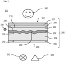
- the layer structure according to the invention which preferably serves as a decorative multi-layer body and is also referred to below as a 3D decoration, is preferably combined with a light source, also referred to as a decorative light, and a display element for displaying information.
- the layer structure according to the invention includes a decorative light effect with two visually different states: In a first state, the 3D structure is made optically visible by means of a light source with high contrast, while the 3D structure remains invisible to the eye in a second state in an ambient light environment and as a uniform black panel, gray panel, or white panel area appears.
- the invention also relates to the use of the layer structure according to the invention as a cover for a human-machine communication unit (Human Machine Interface or HMI).
- a human-machine communication unit Human Machine Interface or HMI
- Covers for backlit display elements with transparent polycarbonate carrier are out US2002/0089468 known.
- Colored 2D decorations are also known from this document, which are part of a cover for a display element.
- the cover can be colored opaque as well as transparent Include layers or foils that can absorb, scatter and filter both light from the observer side and light from the backlighting unit (BLU).
- Covers for displays and methods for their production are from the prior art, for example from US2009/268296 , known.
- Combined light and display elements with a common cover panel are off UK 10211270 known.
- the main components of a multifunction display described above are as follows (E1) display element, eg backlit LC flat screen; (E2) Closed black panel cover for these two elements; (E3) light guide plate with LED edge lighting and - backlighting for light element; (E4) Flat screen, for example based on LCD or OLED technology, arranged next to the lighting element.
- the lighting element can be a second display element that can make symbols and 2D-printed decorations visible by means of backlighting.
- the so-called black panel cover is characterized by the fact that it appears black and optically hides the elements on the back in the ambient environment until one of the elements is activated, i.e. emits light. Light emitted by the lighting element can also reach into the area of the display element, so that this area is also used as area light.
- thermoplastic film layer that carries optical information (decoration) that is back-injected with a polycarbonate or polycarbonate blend carrier.
- the prior art does not have any display covers that carry 3D structures or 3D decorations in the display field of the display.
- 3D plastic decors cannot be used as a display cover because they optically break the image content over the 3D surface in a lens-like manner and thus distort it or hide it due to total internal reflection.
- elements from the prior art cannot be combined with one another in the area of the display without image distortions or distortions or shadowing occurring at least partially across the display area or for certain viewing directions, or without the field of vision being restricted becomes.
- a first task was therefore to at least partially minimize at least one disadvantage from the SdT. Furthermore, it was an object of the invention to provide a cover, e.g the layered structure allows lying displays. Furthermore, it was an object to provide a lighting system that allows display elements (displays), functional lights and 3D decorative lights in closed, decorative thermoplastic to integrate moldings. In particular, a lighting system should be provided, e.g. in the form of a combined lighting and display module with a 3D structure, which does not distort the image, regardless of whether it is illuminated from the front or from the side. Furthermore, it was an object of the invention to provide a combined light and display module with a 3D structure that is built as compactly as possible.
- Another task was to provide a combined lighting and display module with a 3D structure that has a common cover panel for elements grouped behind it and its decorative light and display functions overlap laterally so that they partially or entirely use the same areas in the cover panel without the functional limitations described above. Furthermore, it was an object of the invention to provide a method for producing a cover pane as described above, in the form of a layered structure.
- Layer b preferably functions. or layer c. as a light-absorbing so-called black panel layer
- the layer b. has a light transmission of 10 to 50%, preferably 15 to 35%, more preferably 20 to 25%, or wherein layer c. has a light transmission of 70 to 92%, preferably from 73 to 85% and a half-value angle for the scattered light of 15 to 50°, preferably from 25 to 50° and thus serves as a light-scattering so-called white panel or gray panel layer.
- the light transmission is determined according to DIN EN ISO 13468-2:2006-7.
- Layer b. or layer c. particularly preferably layer b. and layer c., a light transmission of 0 to 95%, preferably 1 to 92%, more preferably 10 to 93%, determined according to DIN EN ISO 13468-2:2006-7.
- the first layer a. and the further layer b. each preferably form an outside of the layer structure.
- the first layer a. is also referred to below as the front or visible side of the layer structure, with or without further coating.
- the front side is the side of the sandwich that is seen by a viewer of the sandwich built into a lighting fixture. This is thus the side from which a viewer should and can view the 3D decoration when appropriately illuminated.
- the inside or back of the layer structure is the side that faces possible display elements or backlighting and that from the further layer b. is formed with or without further coating.
- parallel means a deviation of the surfaces A from B by less than 5°, preferably less than 3°.
- surfaces A′ or B′ arranged at an angle mean that the surfaces A′ or B′ are opposite to the surfaces A or B of the layers a. or b. at least at one point they are not coplanar with one another, so that their surface elements can enclose an angle of up to 85°.
- the angling of surface A' to surface A and the angling of surface B' to surface B is preferably in a range from 2 to 85°, more preferably in a range from 3 to 45°, particularly preferably in a range of 3 up to 30°.
- the portion in which surface A' is angled relative to surface A is preferably 10 to 99%, more preferably 15 to 95%, particularly preferably 20 to 95%, based on the total area of surface A'.
- the portion in which surface B' is angled relative to surface B is preferably 10 to 99%, more preferably 15 to 95%, particularly preferably 20 to 95%, based on the total area of surface B'.
- the surface elements of the surfaces A′ and B′ preferably run almost parallel to one another, so that a regular 3D structure is formed.
- Almost parallel means a deviation of the surfaces A′ from B′ of less than 5°, preferably less than 3° and particularly preferably less than 1°.
- the 3D structure can be any shape one skilled in the art would choose.
- the 3D structures are preferably selected from the group consisting of zigzag, wavy, in particular sinusoidal, or combinations of at least two of these.
- the layer a a thickness in a range from 100 ⁇ m to 7 mm, preferably in a range from 150 ⁇ m to 5 mm, particularly preferably in a range from 200 ⁇ m to 2 mm.
- the layer a. a thickness deviation over their entire surface area of less than 20%, preferably less than 10%, particularly preferably less than 5%.
- the layer b. a thickness in a range from 100 ⁇ m to 7 mm, preferably in a range from 150 ⁇ m to 5 mm, particularly preferably in a range from 200 ⁇ m to 2 mm.
- the layer b. a thickness deviation over their entire surface area of less than 20%, preferably less than 10%, particularly preferably less than 5%.
- the layer c. a thickness in a range from 10 to 1000 ⁇ m, preferably in a range from 50 to 750 ⁇ m, particularly preferably from 125 to 600 ⁇ m, very particularly preferably from 250 to 500 ⁇ m, most preferably from 300 to 400 ⁇ m.
- the layer c. a thickness deviation over their entire surface area of less than 20%, preferably less than 10%, particularly preferably less than 5%.
- the layer structure preferably has a thickness in a range from 350 ⁇ m to 10 mm, particularly preferably in a range from 2 to 6 mm.
- the layer structure preferably has a thickness deviation of less than 20%, preferably less than 10%, particularly preferably less than 5%, over its entire surface area.
- the layer c. formed 3D structure prefers a depth extension within the layer structure, which is perpendicular to the parallel surfaces A and B of the layers a. and b. extends, in an area of 100 to 1000 ⁇ m, more preferably in a range from 150 to 800 ⁇ m, particularly preferably in a range from 200 to 500 ⁇ m.
- the layers a., b. or c. each independently of one another preferably have a surface area in a range from 1 cm 2 to 10 m 2 , more preferably in a range from 10 cm 2 to 5 m 2 , particularly preferably in a range from 100 cm 2 to 1 m 2 .
- the layer structure preferably has a property or combination of properties selected from the group consisting of (E1); (E2); (E3); (E4); (E5); (E1) and (E2); (E1) and (E3); (E1) and (E4); (E1) and (E5); (E2) and (E3); (E2) and (E4); (E2) and (E5); (E3) and (E4); (E3) and (E5); (E1) and (E2) and (E4); (E1) and (E2) and (E5); (E1) and (E3) and (E4); (E1) and (E3) and (E5); (E2) and (E3) and (E4); (E2) and (E3) and (E5); (E1) and (E2) and (E3) and (E4); (E2) and (E3) and (E5); (E1) and (E2) and (E3) and (E4); (E2) and (E3) and (E5); (E1) and (E2) and (E3) and (E
- At least one, preferably all of the layers b., or c. have a light transmission of 5 to 95%, preferably 7 to 93%, more preferably 10 to 92%, determined according to DIN EN ISO 13468-2:2006-7.
- layer c. has a light transmission of 5 to 95%, preferably 7 to 93%, more preferably 10 to 92%, determined according to DIN EN ISO 13468-2:2006-7.
- the layer structure preferably has the following feature: (E4) at least one of the layers b. or c. has an absorption range in the visible spectrum.
- the layer c. is designed as a light-scattering layer, in particular with a light transmission of 70 to 92%, preferably 73 to 85% and a half-value angle for the scattered light of 15 to 50°, preferably 25 to 50°.
- the layer c. is refractive index matched to the layers a. and b.. This makes the 3D structure invisible in the ambient light environment and when all artificial light sources, backlighting and LED edge lights are switched off.
- refractive index matched is meant that the refractive indices D of the layers b. and c. and the layers a. and c. in each case by ⁇ 0.1, preferably by ⁇ 0.05, more preferably by ⁇ 0.04 preferably differ by ⁇ 0.03.
- the refractive index D is defined as the ratio of the speed of light in a vacuum to the speed of light in the medium (layer) and refers to the sodium D line at the wavelength of 589 nm, which is also the standard wavelength for refractometers. Unless otherwise stated, it was determined according to ISO 489 (Method A).
- the layers a. and b. preferably have or consist of a thermoplastic material.
- Layer c. also a thermoplastic material.
- the thermoplastic material is preferably selected from the group consisting of aromatic polycarbonate (PC), including copolycarbonate, polyester carbonate, polystyrene (PS), styrene copolymers such as transparent polystyrene acrylonitrile (PSAN), polyalkylenes such as polyethylene (PE) and polypropylene (PP), aromatic polyesters such as polyethylene terephthalate (PET) and polybutylene terephthalate (PBT), PET-cyclohexanedimethanol copolymer (PETG), polyethylene naphthalate (PEN), polyphenylene ether (PPE), polyacrylate, copolyacrylate, in particular poly- or copolymethyl methacrylates such as polymethyl methacrylate (PMMA), polyimides (e.g.
- thermoplastic material is preferably transparent.
- the thermoplastic material is preferably based on aromatic polycarbonate and/or polymethyl methacrylate, particularly preferably on aromatic polycarbonate or consists of it.
- thermoplastic polymers in particular in the form of thermoplastic polymers, are mentioned in connection with the method according to the invention, described further below, for producing a layer structure, which is why reference is made at this point to their description. All thermoplastic materials described in connection with the method according to the invention, their compositions, including quantitative ratios, production and properties are also for the corresponding layers a., b. and c. of the layer structure according to the invention.
- At least one of the layers a. or b. a glass selected from the group consisting of a quartz glass, a borosilicate glass, a fluorosilicate glass, a fluoride glass, a boron phosphate glass, a lead glass, an aluminosilicate glass or a combination of at least two of these.
- Bubble-free according to the invention means that no bubbles can be seen with the naked eye, preferably at a magnification of 20x.
- the further layer c. a transparent, thermoplastic polymer, preferably selected from the group consisting of a polycarbonate, a copolycarbonate, a polymethyl methacrylate (PMMA), a Polyethylene terephthalate (PET), a blend containing at least one of the above polymers or a mixture of at least two thereof.
- a transparent, thermoplastic polymer preferably selected from the group consisting of a polycarbonate, a copolycarbonate, a polymethyl methacrylate (PMMA), a Polyethylene terephthalate (PET), a blend containing at least one of the above polymers or a mixture of at least two thereof.
- the layer c is preferably a technical film or a coating, while the two outer layers a. and b. preferably consist of a thermoplastic material which can be produced by means of an injection molding or direct coating process (engl.: Direct Coating, Direct Skinning).
- This layer c. serves to represent a decor through its deformation (so-called 3D decor) or at the same time to represent a decor or one or more symbols and text through further finishing steps such as printing (so-called 2D decors).
- the layer c. is preferably a thermoplastic film, preferably consisting of polycarbonate.
- layer c. contain or consist of one of the following materials: PMMA, PET.
- Makrofol ® LM polycarbonate black panel film Makrofol ® LM polycarbonate diffuser film (manufacturer: Covestro AG, Germany), Hostaphan ® WNL translucent white polyester film for laminating applications, Hostaphan ® YNK yellow polyester film (manufacturer: Mitsubishi Polyester Film GmbH, Germany), PLEXIGLAS ® Foils in transparent blue, yellow, green, red, orange and brown (manufacturer: Röhm GmbH, Germany).
- Layer c is preferred. provided with optical information by means of laser structuring, inkjet printing, laser printing, digital printing, offset printing or screen printing.
- Different printing technologies offer different advantages: Screen printing is the most common printing process for polycarbonate films, where printing is done directly onto the medium. Screen printing produces durable, long-lasting printed images with high opacity and color density. Due to the high printing speed, offset printing is particularly suitable for the economical production of large runs and for the creation of very fine line patterns. Finally, digital printing allows for complete flexibility at high speed and volume as no printing forme or plate is required and the technology can be used to print on demand down to single runs.
- the layers a. and b. the same material. Furthermore, all three layers a., b. and c. the same material.
- the material of layer a is preferred. and b. a polycarbonate.
- the material of layers a., b and c is preferred. a PMMA.
- the material of layers a., b and c is also preferred. a polyamide.
- the layer structure preferably has a property or combination of properties selected from the group consisting of a1.; a2.; a3.; a4.; a5.; a6. a1. and a2.; a1. and a3.; a1. and a4.; a1. and a5.; a1. and a6.; a2. and a3.; a2. and a4.; a2. and a5.; a2. and a6.; a3. and a4.; a3. and a5.; a3. and a6.; a4. and a5.; a4. and a6.; a5. and a6.; a1. and a2. and a3.; a1. and a2.
- the layer b. the layer structure has a property or combination of properties selected from the group consisting of b1.; b2.; b3.; b4.; b5.; b6. b1. and b2.; b1. and b3.; b1. and b4.; b1. and b5.; b1. and b6.; b2. and b3.; b2. and b4.; b2. and b5.; b2. and b6.; b3. and b4.; b3. and b5.; b3. and b6.; b4. and b5.; b4. and b6.; b5. and b6.; b1. and b2. and b3.; b1. and b2.
- the layer c. the layer structure has a property or combination of properties selected from the group consisting of c1.; c2.; c3.; c4.; c1. and c2.; c1. and c3.; c1. and c4.; c2. and c3.; c2. and c4; c3. and c4.; c1. and c2. and c3.; c1. and c2. and c4.; c2. and c3. and c4.; c1. and c2. and c3. and c4.; c2. and c3. and c4.; c1. and c2. and c3. and c4.; particularly preferably c1. and c2. and c3. or c1. and c2. and c3. and c4 up.
- the layer structure has the feature (A5) and particularly preferably the combination of features (A1) and (A2) and (A5) or (A1) and (A2) and (A4) and (A5).
- Casting in step I) can be done in any way known to those skilled in the art to cast polymers.
- the casting is preferably selected from the group consisting of injection molding, variothermal injection molding, injection compression molding and low-pressure injection molding.
- the latter includes the Reaction Injection Molding (RIM) process.
- Laying on the further layer c. onto the angled surface A' in step II) can be done by any type of lay-up that the skilled person would select for this.
- the application preferably takes place by a method selected from the group consisting of compressed air pressing, vacuum drawing or placing the film in the tool.
- Casting in step III) can be done in any way known to those skilled in the art to cast polymers.
- the casting is preferably selected from the group consisting of injection molding with film inserts, called film back injection molding (FIM method), but variothermal injection molding, injection compression molding and low-pressure injection molding are also possible.
- FIM method film back injection molding
- RIM Reaction Injection Molding
- the polymer can be any polymer that one skilled in the art would select for layer construction.
- the liquefied polymer is preferably selected from the group consisting of polycarbonate, a polyurethane, a thermoplastic polyurethane or a mixture of at least two of these.
- the polycarbonates are both homopolycarbonates and copolycarbonates.
- the polycarbonates can be linear or branched in a known manner. Insofar as "polycarbonates" are mentioned in the context of the present invention, aromatic polycarbonates are always meant, even if not explicitly mentioned.
- the polycarbonates are produced in a known manner from dihydroxyaryl compounds, carbonic acid derivatives, optionally chain terminators and branching agents.
- dihydroxyaryl compounds suitable for producing the polycarbonates are hydroquinone, resorcinol, dihydroxydiphenyls, bis(hydroxyphenyl)alkanes, bis(hydroxyphenyl)cycloalkanes, bis(hydroxyphenyl) sulfides, bis(hydroxyphenyl) ethers, bis(hydroxyphenyl).
- Preferred dihydroxyaryl compounds are 4,4'-dihydroxydiphenyl, 2,2-bis(4-hydroxyphenyl)propane, 2,4-bis(4-hydroxyphenyl)-2-methylbutane, 1,1-bis(4-hydroxyphenyl).
- dihydroxyaryl compounds are 4,4'-dihydroxydiphenyl, 1,1-bis(4-hydroxyphenyl)phenylethane, 2,2-bis(4-hydroxyphenyl)propane, 2,2-bis(3, 5-dibromo-4-hydroxyphenyl)propane, 2,2-bis(3,5-dichloro-4-hydroxyphenyl)propane, 2,2-bis(3,5-dimethyl-4-hydroxyphenyl)propane, 1,1-bis(4-hydroxyphenyl)cyclohexane and 1,1-bis(4-hydroxyphenyl)-3,3,5-trimethylcyclohexane (Bisphenol TMC) and the dihydroxyaryl compounds of the formulas (I), (II) and /or (III).
- Suitable carbonic acid derivatives are phosgene or diphenyl carbonate.
- Suitable chain terminators that can be used in the production of the polycarbonates are both monophenols and monocarboxylic acids.
- suitable monophenols are phenol itself, alkylphenols such as cresols, p-tert-butylphenol, cumylphenol, p-n-octylphenol, p-isooctylphenol, p-n-nonylphenol and p-isononylphenol, halophenols such as p-chlorophenol, 2,4-dichlorophenol, p-bromophenol and 2,4,6-tribromophenol, 2,4,6-triiodophenol, p-iodophenol, and mixtures thereof.
- Preferred chain terminators are also the phenols which are mono- or poly-substituted by linear or branched C 1 - to C 30 -alkyl radicals, preferably unsubstituted or substituted by tert-butyl.
- Particularly preferred chain terminators are phenol, cumylphenol and/or p-tert-butylphenol.
- Suitable monocarboxylic acids are also benzoic acid, alkyl benzoic acids and halobenzoic acids.
- the amount of chain terminator to be used is preferably 0.1 to 5 mol %, based on moles of dihydroxyaryl compounds used in each case.
- the chain terminators can be added before, during or after the reaction with a carbonic acid derivative.
- Suitable branching agents are the trifunctional or more than trifunctional compounds known in polycarbonate chemistry, in particular those having three or more than three phenolic OH groups.
- Other suitable branching agents are, for example, phloroglucinol, 4,6-dimethyl-2,4,6-tri-(4-hydroxyphenyl)-heptene-2, 4,6-dimethyl-2,4,6-tri(4-hydroxyphenyl)- heptane, 1,3,5-tri(4-hydroxyphenyl)benzene, 1,1,1-tri(4-hydroxyphenyl)ethane, tri(4-hydroxyphenyl)phenylmethane, 2,2-bis[ 4,4-bis(4-hydroxyphenyl)cyclohexyl]propane, 2,4-bis(4-hydroxyphenylisopropyl)phenol, 2,6-bis(2-hydroxy-5'-methyl-benzyl)- 4-methylphenol, 2-(4-hydroxyphenyl)-2-(2,4-dihydroxyphenyl)
- the amount of any branching agents to be used is preferably 0.05 mol % to 2.00 mol %, again based on moles of dihydroxyaryl compounds used in each case.
- the branching agents can either be initially taken with the dihydroxyaryl compounds and the chain terminators in the aqueous-alkaline phase or, dissolved in an organic solvent, can be added before the phosgenation. In the case of the transesterification process, the branching agents are used together with the dihydroxyaryl compounds.
- the aromatic polycarbonates are preferably produced by the interfacial process.
- Linear polycarbonates are preferably used.
- the aromatic polycarbonates preferably have weight-average molecular weights Mw between 10,000 and 50,000 g/mol, more preferably between 14,000 and 40,000 g/mol, even more preferably between 15,000 and 35,000 g/mol, particularly preferably between 18,000-32,000 g/mol, very particularly preferably between 20,000 and 28,000 g/mol.
- the values apply to the determination by gel permeation chromatography, using dichloromethane as the eluent, calibration with linear polycarbonates (from bisphenol A and phosgene) of known molar mass distribution from PSS Polymer Standards Service GmbH, Germany, calibration according to method 2301-0257502-09D (from the years 2009 in German) of Currenta GmbH & Co. OHG, Leverkusen.
- the eluent is also dichloromethane when calibrating.
- RI refractive index
- the MVR value of the aromatic polycarbonate measured according to ISO 1133:2012-03 at 300° C. and 1.2 kg, is preferably 5 to 35 cm 3 /(10 min), more preferably 10 to 20 cm 3 /(10 min ).
- the MW and MVR data refer to the aromatic polycarbonates contained in the composition of the thermoplastic polymer in their entirety.
- Particularly preferred polycarbonates are the homopolycarbonate based on bisphenol A, the homopolycarbonate based on 1,3-bis-(4-hydroxyphenyl)-3,3,5-trimethylcyclohexane and the copolycarbonates based on the two monomers bisphenol A and 1,1 -bis(4-hydroxyphenyl)-3,3,5-trimethylcyclohexane.
- thermoplastic material preferably comprises further customary additives.
- additives such are, for example, flame retardants, antistatic agents, UV absorbers, stabilizers, antioxidants and mold release agents.
- Suitable ultraviolet absorbers are benzotriazoles, triazines, benzophenones and/or arylated cyanoacrylates. Phosphites and phosphonites and phosphines are preferred as stabilizers.
- alkyl phosphates z.
- Suitable mold release agents are, for example, those based on a fatty acid ester, preferably a stearic acid ester, particularly preferably based on pentaerythritol. Pentaerythritol tetrastearate (PETS) and/or glycerol monostearate (GMS) are preferably used.
- PETS Pentaerythritol tetrastearate
- GMS glycerol monostearate
- the composition of the thermoplastic polymer particularly preferably contains less than 0.1% by weight, and the composition of the thermoplastic polymer is particularly preferably free of scattering additives, e.g silica. Furthermore, the composition of the thermoplastic polymer particularly preferably contains less than 0.1% by weight, and it is very particularly preferably free of white pigments or similar pigments such as titanium dioxide, kaolin, barium sulfate, zinc sulfide, aluminum oxide, aluminum hydroxide, quartz flour, of interference pigments and/or pearlescent pigments, i.e. platelet-shaped particles such as mica, graphite, talc, SiO2, chalk and/or titanium dioxide, coated and/or uncoated.
- white pigments or similar pigments such as titanium dioxide, kaolin, barium sulfate, zinc sulfide, aluminum oxide, aluminum hydroxide, quartz flour, of interference pigments and/or pearlescent pigments, i.e. platelet-shaped particles such as mica, graphite, talc, SiO2, chalk and
- the composition of the thermoplastic polymer particularly preferably contains less than 0.1% by weight; the composition of the thermoplastic polymer is very particularly preferably free of nanoparticulate systems such as metal particles, metal oxide particles.
- the composition of the thermoplastic polymer also contains less than 0.1% by weight, particularly preferably it is free of pigments based on insoluble pigments, such as those found in DE10057165A1 and in WO 2007/135032 A2 are described.
- the designation "3D structure” includes patterns, textures and grains that have a spatial arrangement and distribution of individual structural elements that are introduced into the surface in a targeted manner, from which a visual impression of an optical design is created for the viewer.
- structural elements are included whose lateral extent has dimensions of preferably at least 1 mm, more preferably greater than 3 mm, particularly preferably greater than 5 mm.
- the surface normals of these structural elements preferably have an angular deviation of 2 to 85°, preferably 3 to 45°, particularly preferably 3 to 30°, based on the surface normals of the adjacent structural elements.
- the height of the 3D structural elements is preferably in the range from 0.1 mm to half the minimum thickness of layer a. in the field of 3D structure. "From"/"to” includes the specified lower or upper limit.
- the height of the 3D structure designates the difference between the highest and the lowest point of the structure, which corresponds to the difference between the minimum and maximum wall thickness in relation to the layer structure cross section.
- the light source ii. is preferably referred to as edge light. It preferably consists of an elongated LED module or LED strip with so-called individual LEDs arranged in a row.
- a single LED can be a white light LED or an RGB LED group.
- the light source iv. is preferably referred to as transmitted light. It preferably consists of an LED panel with individual LEDs preferably arranged in a matrix. A single LED can be a white light LED or an RGB LED group.
- the light source is iv. an ISELED LED module or a passive matrix LED display.
- the light source iv. can alternatively be a diffuse area light, such as in the U.S. 2004/0066645 A1 described.
- the light source iv. can be used alone or in combination with a display iii. be used. Combinations of different backlighting elements consisting of displays and light sources are conceivable.
- the areas of the lateral edge, which are used for coupling light into layer a, preferably allow largely vertical transmission.
- the surface is preferably concave in front of the LED; in the case of individual LEDs with collimation optics, the surface is preferably flat.
- the layer structure according to the invention it is possible for the first time to place imaging display elements such as dot-matrix displays behind 3D relief structures, because the layer structure according to the invention makes it possible to transmit light from this display without light affecting the geometric 3D structures of the Decor is broken, bent or scattered so much that the quality of the display, measurable e.g. by the resolution, homogeneity, luminance, color precision or contrast, is significantly degraded.
- a 3D decor can be illuminated and thus made visible to the eye from the front.
- the side light source such as LED edge modules
- the layer structure according to the invention is preferably selected with elements from the group consisting of one or more displays, with one or more edge lighting and with one or more transmitted light units or a combination of at least two of these.
- the layer structure according to the invention is preferably used as a display cover.
- the layer structure according to the invention is preferably used as a sensor cover.
- Preferred sensors are selected from the group consisting of interior cameras, interior LiDARe, RADARe, infrared cameras, high dynamic range cameras or a combination of at least two of these.
- the layer structure according to the invention is preferably used as an antenna cover.
- Antennas are 5G antennas, for example.
- the lighting system forms part of the body of a vehicle, which is used for communication with people.
- the part of the body is preferably selected from the group consisting of a radiator grille, a bumper, a front grille, roof module, sensor box, bumper, functional light, rear light, headlight and all other lights for vehicle exterior applications, or a combination of at least two of them.
- the lighting system covers part of the vehicle interior surface in order to display an HMI or ambient lighting.
- the light source ii. around an LED edge lighting.
- the senor is v. selected from the group consisting of interior cameras, interior LiDARe, RADARe, infrared cameras, high dynamic range cameras or a combination of at least two of these.
- FIG 1 shows a layered structure in the form of a display cover 100 according to the prior art.
- the display cover 100 consists of a transparent or translucent glass body 110, the surface 120 of which can be equipped with polymer functional layers, for example for shatter protection or optical anti-reflection coating. Underneath there is a polymer layer 130 and a transparent conductive layer 140 which serves as an electrode for a touch function.
- the surface 120 and internal interfaces are smooth.
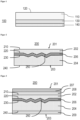
- figure 2 shows a schematic structure of a layer structure 200 according to the invention.
- a zigzag-shaped layer c. 206 in the form of a polycarbonate layer sandwiched between two polycarbonate layers comprising layers a. 202 and layer b. 204 represent.
- the layer a. 202 points in the direction of the front or visible side 201 of the layered structure 200 and is thus aligned with a potential viewer.
- the layer b. 204 points in the direction of the inside 203 of a lighting system in which the layer structure 200 can be installed.
- the layer a. 202 forms an outer surface A 210 and a surface A' 220 angled to the surface A 210.
- the 204 forms an outer surface B 240 and a surface B' 230 angled to the surface B 240.
- the surfaces A 210 and B 240 are parallel to each other.
- Between layer a. 202 and layer b. 204 is the layer c in an angled form. 206 arranged.
- the layer c. 206 follows the contour formed by the surfaces A' 220 and B' 230 and forms a 3D structure 250 in the layer structure 200.
- figure 3 shows a schematic structure of a layer structure 200 according to the invention as shown in figure 2 is shown with the addition that on layer a. 202 as well as on layer b. 204 in each case a further layer 208 or 209 is attached.
- the layer 208 is a protective layer that protects the layer structure 200 from scratching or from the effects of chemicals.
- the layer 209 is either a protective layer that protects the layer structure 200 against scratching or the effects of chemicals, or a transparent electrode for the touch function.
- a layer 207 can be attached to at least one side of the layer structure 200 as an alternative or in addition to the layers 208 or 209 .
- the layer 207 is one or more layers selected from the group consisting of an anti-reflection layer, a low-reflection layer and an anti-fingerprint layer or a combination of at least two of these. In the figure 3 only the variant is shown that on the front, i.e. the side on which the layer a. is located, the additional layer 207 is arranged. However, any combination of layers 207, 208 and 209 is possible.
- FIG 4 shows a lighting system 300, which has a layer structure 200 according to the invention, as shown in figure 3 was described.
- the lighting system 300 has at least one light source 310 and/or a sensor 320 and at least one LED edge lighting 330 which couples light into the layer 202 .
- figure 5 shows four examples 5a, 5b, 5c, and 5d for different states of the lighting installation 300 according to the invention figure 4 , shown on one and the same layer structure 200.
- the display 310 and the layer structure 200 according to the invention are each shown schematically in cross section on the left and a photograph 400 of the front side or visible side 201 is shown on the right.
- a switched-off display 310 shown schematically as a rectangle
- the switched-off edge LED 390 are shown as the light source.
- Photo 400 shows a dark area, ie the black panel effect.
- state 5b the display 310 is off and the edge LED 390 (shown schematically as a lightbulb) is on.
- Photo 401 shows a 3D decorative surface in which the 3D structure 250 has been rendered visible to the viewer's eye.
- the display 310 is on and the edge LED 390 is on.
- the photo 402 shows a 3D decorative surface, with a 3D structure 250 made visible, which is illuminated by the light of the display 310 and is therefore outshined at the locations in the image area illuminated by the display 310 .
- the image of the display 310 appears free of distortion.
- state 5d the display 310 is on and the edge LED 390 is off.
- the photo 403 shows a dark area (black panel effect), which is only outshined in the image area of the display 310.
- the image of the display 310 appears free of distortion, without the 3D structure 380 being discernible.
- Transparent Makrolon® Ai from Covestro Deutschland AG: aromatic polycarbonate based on bisphenol A with an MVR of 19 cm 3 /(10 min), determined at 300° C. and 1.2 kg in accordance with DIN ISO 1133:2012-03 , containing UV absorbers and mold release agents.
- Ty measured at a thickness of 2 mm according to ISO 13468-2:2006 (D65, 10°): 88.07%.
- Haze determined according to ASTM D1003:2013 at a layer thickness of 2 mm: 0.68%.
- the polycarbonate was in the form of granules for injection molding. For pretreatment, the polycarbonate was dried in dry air at 120° C. for 4 hours. The polycarbonate has a refractive index of 1.585 according to ISO 489 (Method A).
- the intermediate layer c. was used: Makrofol ® LM 296 1-2 760125 from Covestro Deutschland AG: gray colored extruded film based on the polycarbonate Makrolon ® .
- the extruded film has a refractive index of 1.596 according to ISO 489 (Method A).
- the foils were each cut to the dimensions 200 mm ⁇ 150 mm with a thickness of 0.5 mm. They had a glossy surface on the 1st side and a very fine matted surface on their 2nd side.
- a metallic plate tool insert was provided with a 3D structure as shown in Figure B1.1.
- Figure B1.2 shows typical structure sizes of the individual elements of 7 to 16 mm and a height of the 3D structure elements of 0.49 mm. This results in an angle of 3.35° between the structural surface normal and the flat and smooth second wall of the injection mold.
- This structure is therefore suitable for producing layer structures according to the invention and for enabling experimental verification of the desired effects in layer structures according to the invention.
- Figure B1.1 3D model of a structure with pyramidal elements of different distribution on a plate with surface dimensions 200 mm x 150 mm.
- Figure B1.2 Dimensions of the pyramidal elements [mm]. Above: side view. Below: top view.
- injection-molded sample plates with a 3D structure on the back and dimensions of 200 mm ⁇ 150 mm ⁇ 3 mm were produced from polycarbonate compositions.
- the light transmission of the Makrofol ® film was 25% according to DIN ISO 13468-2:2006 (D65, 10°). This means it can be used as a black panel film.
- a multi-layer molded part measuring 200 mm ⁇ 150 mm ⁇ 6 mm was produced on an HM270 injection molding machine from Wittmann Battenfeld GmbH.
- a Makrofol ® film was placed as layer c., made of the material mentioned above, into that mold half of a steel mold with the mold inner dimensions 200 mm x 150 mm x 3 mm, the surface of which had the above-described and in Figure B1 .1 shown 3D structure was provided.
- the other half of the tool had a high-gloss finish.
- the transparent polycarbonate material melted at 305 °C was injected into the mold with a maximum specific injection pressure of approx. 2000 bar in order to layer a. to build.
- the film of layer c. was pressed into the structure of the mold surface during this overmolding. It didn't matter which side of the surface, i.e.
- the smooth side 1 or the rough side 2 was inserted to form the structure.
- the temperature of the mold wall was 90 °C on both sides, i.e. both on the ejector side and on the opposite injection side.
- the injection time was about 2.5 seconds.
- the tool was opened and the molded part was removed.
- the Makrolon layer forms layer a.; the Makrofol film layer c, hereinafter referred to as the polycarbonate sheet.
- the injection mold was then converted to the internal dimensions of 200 mm x 150 mm x 6 mm and the structured steel surface was removed so that both mold halves now had a high-gloss surface.
- the polycarbonate plate was preheated with the 3D structured side at 90° C. in a heating cabinet for 15 minutes. This plate was then placed back into the first mold half of the steel mold with the internal mold dimensions 200 x 150 x 6 mm, showing the structured surface with the respective foil to the second mold half. After the mold was closed, the transparent polycarbonate material, melted at 305 °C, was injected into the mold onto the polycarbonate sheet, on the side with the 3D structured film, with a maximum specific injection pressure of approx. 2000 bar.
- the temperature of the mold wall was 100 °C on the ejector side and 80 °C on the opposite injection side.
- the injection time was again 2.5 seconds.
- the tool was opened and the finished molded part with a total thickness of about 6 mm and two high-gloss sides was removed.
- the layer structure obtained now has a further layer b., and has the three-layer structure according to the invention with an internal 3D structure in the form of the structured “black panel film”.
- the light transmission of the layer structure obtained was 21% according to DIN ISO 13468-2:2006 (D65, 10°).
- the visual effects are characterized by the images figure 5 illustrated.
- layer a. and b. contained Makrolon ® as in Example 1, but for the intermediate layer c.
- the extruded film has a refractive index of 1.59 according to ISO 489 (method A).
- layer a. and b. contained Makrolon ® as in Example 2, but for the intermediate layer c. used: Makrofol® LM 296 1-2 from Covestro Deutschland AG: gray-colored extrusion film based on the polycarbonate Makrolon® and a transmission according to DIN ISO 13468-2:2006 (D65, 10°) of 75%.
- the extruded film has a refractive index of 1.59 according to ISO 489 (method A).
- the optical effects could be achieved to a large extent with this layer structure.
- the display image is even brighter, the 3D decor is subjectively even lower in contrast and the 3D structure is easily discernible in the ambient light (e.g. office room with indirect ceiling light).
- the display could be read clearly through the 3D structure no matter whether the edge light was on or not.
- the 3D structure was clearly visible with the edge light on.
- layer a. and b. contained Makrolon ® as in Example 1, but for the intermediate layer c. used: Makrofol ® LM 309 from Covestro Deutschland AG: 300 ⁇ m thick diffuser film based on the polycarbonate Makrolon ® , a transmission according to DIN ISO 13468-2:2006 (D65, 10°) of 86% and a half-power angle of 20° according to DIN 5036 :1978 related to light intensity.
- the visual evaluation was carried out as in the previous examples. All optical effects could also be displayed with this layer structure. Instead of the black panel effect, a so-called white panel effect appeared here: the diffuser film as layer c. scattered ambient light back to the observer. This structureless light in conjunction with wide scattering angles optically resolved the 3D structure and gave the observer the impression of a uniformly whitish bright surface. Because the level of the display panel was only about 4 mm behind the level of the diffuser, the display image still appeared sharp. The diffuser effect even improved image brightness when observing from an oblique position. With the white panel film, the 3D decor can be designed to be invisible in an ambient light environment when the edge lighting is switched off and made visible by edge lighting. The same applies to backlighting (display): they are invisible when switched off and visible when switched on.
Landscapes
- Laminated Bodies (AREA)
Applications Claiming Priority (1)
| Application Number | Priority Date | Filing Date | Title |
|---|---|---|---|
| EP21217625 | 2021-12-23 |
Publications (1)
| Publication Number | Publication Date |
|---|---|
| EP4201664A1 true EP4201664A1 (fr) | 2023-06-28 |
Family
ID=79021899
Family Applications (1)
| Application Number | Title | Priority Date | Filing Date |
|---|---|---|---|
| EP22214036.0A Pending EP4201664A1 (fr) | 2021-12-23 | 2022-12-16 | Couvercle d'affichage et de lumière à décor tridimensionnel |
Country Status (1)
| Country | Link |
|---|---|
| EP (1) | EP4201664A1 (fr) |
Cited By (1)
| Publication number | Priority date | Publication date | Assignee | Title |
|---|---|---|---|---|
| DE102022130159A1 (de) | 2022-11-15 | 2024-05-16 | Morino Stübe | Displayschutzeinrichtung und verfahren zu deren herstellung |
Citations (22)
| Publication number | Priority date | Publication date | Assignee | Title |
|---|---|---|---|---|
| US2991273A (en) | 1956-07-07 | 1961-07-04 | Bayer Ag | Process for manufacture of vacuum moulded parts of high molecular weight thermoplastic polycarbonates |
| US2999835A (en) | 1959-01-02 | 1961-09-12 | Gen Electric | Resinous mixture comprising organo-polysiloxane and polymer of a carbonate of a dihydric phenol, and products containing same |
| US2999846A (en) | 1956-11-30 | 1961-09-12 | Schnell Hermann | High molecular weight thermoplastic aromatic sulfoxy polycarbonates |
| US3148172A (en) | 1956-07-19 | 1964-09-08 | Gen Electric | Polycarbonates of dihydroxyaryl ethers |
| US3271367A (en) | 1955-03-26 | 1966-09-06 | Bayer Ag | Thermoplastic polycarbonates of dihydroxydiarylene sulfones and their preparation |
| FR1561518A (fr) | 1967-03-10 | 1969-03-28 | ||
| DE1570703A1 (de) | 1964-10-07 | 1970-02-12 | Gen Electric | Hydrolytisch stabile Polycarbonate sowie Verfahren zu deren Herstellung |
| DE2036052A1 (en) | 1970-07-21 | 1972-01-27 | Milchwirtschafthche Forschungs und Untersuchungs Gesellschaft mbH, 2100 Hamburg | Working up of additives in fat and protein - contng foodstuffs |
| DE2063050A1 (de) | 1970-12-22 | 1972-07-13 | Bayer | Verseifungsbeständige Polycarbonate |
| DE2211956A1 (de) | 1972-03-11 | 1973-10-25 | Bayer Ag | Verfahren zur herstellung verseifungsstabiler blockcopolycarbonate |
| DE3832396A1 (de) | 1988-08-12 | 1990-02-15 | Bayer Ag | Dihydroxydiphenylcycloalkane, ihre herstellung und ihre verwendung zur herstellung von hochmolekularen polycarbonaten |
| US4982014A (en) | 1988-08-12 | 1991-01-01 | Bayer Aktiengesellschaft | Dihydroxydiphenyl cycloalkanes, their production and their use for the production of high molecular weight polycarbonates |
| DE10057165A1 (de) | 2000-11-16 | 2002-05-23 | Basf Ag | Pigmentzubereitungen |
| US20020089468A1 (en) | 1997-02-13 | 2002-07-11 | Hans Kurt Wedel | Instrument panel with system of transparent colored layers |
| DE10211270A1 (de) | 2002-03-13 | 2003-10-02 | Siemens Ag | Anzeigeeinrichtung |
| US20040066645A1 (en) | 2002-10-03 | 2004-04-08 | John Graf | Bulk diffuser for flat panel display |
| WO2007135032A2 (fr) | 2006-05-23 | 2007-11-29 | Basf Se | Utilisation de polycarbonates hyperramifiés en tant qu'agents de dispersion pour pigments |
| US20090268296A1 (en) | 2008-04-29 | 2009-10-29 | Motorola, Inc. | Transparent display cover and method of making |
| EP2652029A2 (fr) | 2010-12-17 | 2013-10-23 | Bayer Intellectual Property GmbH | Colorants organiques et compositions polymères colorées à grande stabilité aux intempéries |
| EP2982501A1 (fr) * | 2013-04-05 | 2016-02-10 | Mitsubishi Rayon Co., Ltd. | Corps structurel à microrelief, feuille décorative, corps moulé en résine décorative, procédé permettant de produire un corps structurel à microrelief et procédé permettant de produire un corps moulé en résine décorative |
| US20200012180A1 (en) * | 2017-01-31 | 2020-01-09 | Saint-Gobain Glass France | Layered element made of transparent layers providing directional diffuse reflection |
| WO2020212240A1 (fr) | 2019-04-16 | 2020-10-22 | Covestro Intellectual Property Gmbh & Co. Kg | Agencement en strates comprenant une structure 3d et projection 2d de cette structure |
-
2022
- 2022-12-16 EP EP22214036.0A patent/EP4201664A1/fr active Pending
Patent Citations (22)
| Publication number | Priority date | Publication date | Assignee | Title |
|---|---|---|---|---|
| US3271367A (en) | 1955-03-26 | 1966-09-06 | Bayer Ag | Thermoplastic polycarbonates of dihydroxydiarylene sulfones and their preparation |
| US2991273A (en) | 1956-07-07 | 1961-07-04 | Bayer Ag | Process for manufacture of vacuum moulded parts of high molecular weight thermoplastic polycarbonates |
| US3148172A (en) | 1956-07-19 | 1964-09-08 | Gen Electric | Polycarbonates of dihydroxyaryl ethers |
| US2999846A (en) | 1956-11-30 | 1961-09-12 | Schnell Hermann | High molecular weight thermoplastic aromatic sulfoxy polycarbonates |
| US2999835A (en) | 1959-01-02 | 1961-09-12 | Gen Electric | Resinous mixture comprising organo-polysiloxane and polymer of a carbonate of a dihydric phenol, and products containing same |
| DE1570703A1 (de) | 1964-10-07 | 1970-02-12 | Gen Electric | Hydrolytisch stabile Polycarbonate sowie Verfahren zu deren Herstellung |
| FR1561518A (fr) | 1967-03-10 | 1969-03-28 | ||
| DE2036052A1 (en) | 1970-07-21 | 1972-01-27 | Milchwirtschafthche Forschungs und Untersuchungs Gesellschaft mbH, 2100 Hamburg | Working up of additives in fat and protein - contng foodstuffs |
| DE2063050A1 (de) | 1970-12-22 | 1972-07-13 | Bayer | Verseifungsbeständige Polycarbonate |
| DE2211956A1 (de) | 1972-03-11 | 1973-10-25 | Bayer Ag | Verfahren zur herstellung verseifungsstabiler blockcopolycarbonate |
| DE3832396A1 (de) | 1988-08-12 | 1990-02-15 | Bayer Ag | Dihydroxydiphenylcycloalkane, ihre herstellung und ihre verwendung zur herstellung von hochmolekularen polycarbonaten |
| US4982014A (en) | 1988-08-12 | 1991-01-01 | Bayer Aktiengesellschaft | Dihydroxydiphenyl cycloalkanes, their production and their use for the production of high molecular weight polycarbonates |
| US20020089468A1 (en) | 1997-02-13 | 2002-07-11 | Hans Kurt Wedel | Instrument panel with system of transparent colored layers |
| DE10057165A1 (de) | 2000-11-16 | 2002-05-23 | Basf Ag | Pigmentzubereitungen |
| DE10211270A1 (de) | 2002-03-13 | 2003-10-02 | Siemens Ag | Anzeigeeinrichtung |
| US20040066645A1 (en) | 2002-10-03 | 2004-04-08 | John Graf | Bulk diffuser for flat panel display |
| WO2007135032A2 (fr) | 2006-05-23 | 2007-11-29 | Basf Se | Utilisation de polycarbonates hyperramifiés en tant qu'agents de dispersion pour pigments |
| US20090268296A1 (en) | 2008-04-29 | 2009-10-29 | Motorola, Inc. | Transparent display cover and method of making |
| EP2652029A2 (fr) | 2010-12-17 | 2013-10-23 | Bayer Intellectual Property GmbH | Colorants organiques et compositions polymères colorées à grande stabilité aux intempéries |
| EP2982501A1 (fr) * | 2013-04-05 | 2016-02-10 | Mitsubishi Rayon Co., Ltd. | Corps structurel à microrelief, feuille décorative, corps moulé en résine décorative, procédé permettant de produire un corps structurel à microrelief et procédé permettant de produire un corps moulé en résine décorative |
| US20200012180A1 (en) * | 2017-01-31 | 2020-01-09 | Saint-Gobain Glass France | Layered element made of transparent layers providing directional diffuse reflection |
| WO2020212240A1 (fr) | 2019-04-16 | 2020-10-22 | Covestro Intellectual Property Gmbh & Co. Kg | Agencement en strates comprenant une structure 3d et projection 2d de cette structure |
Non-Patent Citations (5)
| Title |
|---|
| D. FREITAGU. GRIGOP.R. MÜLLERH. NOUVERTNEBAYER AG: "Encyclopedia of Polymer Science and Engineering", vol. 11, 1988, article "Polycarbonates", pages: 648 - 718 |
| D.G. LEGRANDJ.T. BENDLER: "Handbook of Polycarbonate Science and Technology", 2000, MARCEL DEKKER, pages: 72 |
| DRES. U. GRIGOK. KIRCHNERP.R. MÜLLER: "Becker/Braun, Kunststoff-Handbuch", vol. 3, 1992, CARL HANSER VERLAG, article "Polycarbonate", pages: 117 - 299 |
| H. SCHNELL: "Chemistry and Physics of Polycarbonates", 1964, INTERSCIENCE PUBLISHERS, pages: 28 |
| SCHNELL: "Polymer Reviews", vol. 9, 1964, INTERSCIENCE PUBLISHERS, article "Chemistry and Physics of Polycarbonates" |
Cited By (1)
| Publication number | Priority date | Publication date | Assignee | Title |
|---|---|---|---|---|
| DE102022130159A1 (de) | 2022-11-15 | 2024-05-16 | Morino Stübe | Displayschutzeinrichtung und verfahren zu deren herstellung |
Similar Documents
| Publication | Publication Date | Title |
|---|---|---|
| EP1312472B1 (fr) | Structure stratifiee d'aspect attrayant et son utilisation | |
| EP1392505B1 (fr) | Systeme a couches, absorbant la chaleur | |
| TWI513759B (zh) | 光散射膜及使用此光散射膜之平面螢幕 | |
| KR20130063506A (ko) | 열 흡수성 및 개선된 염색성을 갖는 폴리머 조성물 | |
| JP2003053908A (ja) | 高意匠性シート状積層構造体およびその利用 | |
| DE102005047615A1 (de) | Lichtstreuende Kunststoffzusammensetzung mit hoher Helligkeit und deren Verwendung in Flachbildschirmen | |
| EP4201664A1 (fr) | Couvercle d'affichage et de lumière à décor tridimensionnel | |
| US6893689B2 (en) | Heat-absorbent multi-layer structure | |
| US9400420B2 (en) | Rear-projection film having a “day/night” effect | |
| MX2008002389A (es) | Moldeos de dispersion de luz con alta transmision de luz. | |
| WO2005087870A1 (fr) | Agent solubilisant et composition contenant celui-ci | |
| US20070224367A1 (en) | Mold multilayered sheet for use as a diffuser in flat screens | |
| WO2021149678A1 (fr) | Équipement d'affichage, élément intérieur et extérieur de véhicule, lampe d'éclairage, panneau d'affichage, et véhicule | |
| EP4037899A1 (fr) | Éléments d'éclairage à del à base d'éléments multicouches présentant un aspect de type pierre | |
| EP4201671A1 (fr) | Couvercle de capteur éclairé avec décor tridimensionnel | |
| EP4035145B1 (fr) | Surface de conception métallisée transparente | |
| EP4037900A1 (fr) | Éléments d'éclairage à del à base de corps multicouches ayant un aspect de pierre massive | |
| US20050013970A1 (en) | Multi-layer product in which the co-extruded side is easily recognizable | |
| EP3805841A1 (fr) | Dispositif d'affichage pourvu de disque de recouvrement en une seule pièce, en particulier pour l'habitacle des véhicules automobiles | |
| WO2018114828A1 (fr) | Structure en couches comportant des symboles pouvant être éclairés et son utilisation | |
| JP2003225973A (ja) | 高意匠性シート状積層構造体およびその利用 |
Legal Events
| Date | Code | Title | Description |
|---|---|---|---|
| PUAI | Public reference made under article 153(3) epc to a published international application that has entered the european phase |
Free format text: ORIGINAL CODE: 0009012 |
|
| STAA | Information on the status of an ep patent application or granted ep patent |
Free format text: STATUS: THE APPLICATION HAS BEEN PUBLISHED |
|
| AK | Designated contracting states |
Kind code of ref document: A1 Designated state(s): AL AT BE BG CH CY CZ DE DK EE ES FI FR GB GR HR HU IE IS IT LI LT LU LV MC ME MK MT NL NO PL PT RO RS SE SI SK SM TR |
|
| STAA | Information on the status of an ep patent application or granted ep patent |
Free format text: STATUS: REQUEST FOR EXAMINATION WAS MADE |
|
| 17P | Request for examination filed |
Effective date: 20240102 |
|
| RBV | Designated contracting states (corrected) |
Designated state(s): AL AT BE BG CH CY CZ DE DK EE ES FI FR GB GR HR HU IE IS IT LI LT LU LV MC ME MK MT NL NO PL PT RO RS SE SI SK SM TR |