EP4201664A1 - Light and display cover with three-dimensional decoration - Google Patents
Light and display cover with three-dimensional decoration Download PDFInfo
- Publication number
- EP4201664A1 EP4201664A1 EP22214036.0A EP22214036A EP4201664A1 EP 4201664 A1 EP4201664 A1 EP 4201664A1 EP 22214036 A EP22214036 A EP 22214036A EP 4201664 A1 EP4201664 A1 EP 4201664A1
- Authority
- EP
- European Patent Office
- Prior art keywords
- layer
- light
- layer structure
- range
- und
- Prior art date
- Legal status (The legal status is an assumption and is not a legal conclusion. Google has not performed a legal analysis and makes no representation as to the accuracy of the status listed.)
- Pending
Links
Images

Classifications
-
- B—PERFORMING OPERATIONS; TRANSPORTING
- B32—LAYERED PRODUCTS
- B32B—LAYERED PRODUCTS, i.e. PRODUCTS BUILT-UP OF STRATA OF FLAT OR NON-FLAT, e.g. CELLULAR OR HONEYCOMB, FORM
- B32B27/00—Layered products comprising a layer of synthetic resin
- B32B27/06—Layered products comprising a layer of synthetic resin as the main or only constituent of a layer, which is next to another layer of the same or of a different material
- B32B27/08—Layered products comprising a layer of synthetic resin as the main or only constituent of a layer, which is next to another layer of the same or of a different material of synthetic resin
-
- B—PERFORMING OPERATIONS; TRANSPORTING
- B32—LAYERED PRODUCTS
- B32B—LAYERED PRODUCTS, i.e. PRODUCTS BUILT-UP OF STRATA OF FLAT OR NON-FLAT, e.g. CELLULAR OR HONEYCOMB, FORM
- B32B17/00—Layered products essentially comprising sheet glass, or glass, slag, or like fibres
- B32B17/06—Layered products essentially comprising sheet glass, or glass, slag, or like fibres comprising glass as the main or only constituent of a layer, next to another layer of a specific material
- B32B17/10—Layered products essentially comprising sheet glass, or glass, slag, or like fibres comprising glass as the main or only constituent of a layer, next to another layer of a specific material of synthetic resin
-
- B—PERFORMING OPERATIONS; TRANSPORTING
- B32—LAYERED PRODUCTS
- B32B—LAYERED PRODUCTS, i.e. PRODUCTS BUILT-UP OF STRATA OF FLAT OR NON-FLAT, e.g. CELLULAR OR HONEYCOMB, FORM
- B32B27/00—Layered products comprising a layer of synthetic resin
- B32B27/18—Layered products comprising a layer of synthetic resin characterised by the use of special additives
-
- B—PERFORMING OPERATIONS; TRANSPORTING
- B32—LAYERED PRODUCTS
- B32B—LAYERED PRODUCTS, i.e. PRODUCTS BUILT-UP OF STRATA OF FLAT OR NON-FLAT, e.g. CELLULAR OR HONEYCOMB, FORM
- B32B27/00—Layered products comprising a layer of synthetic resin
- B32B27/30—Layered products comprising a layer of synthetic resin comprising vinyl (co)polymers; comprising acrylic (co)polymers
- B32B27/308—Layered products comprising a layer of synthetic resin comprising vinyl (co)polymers; comprising acrylic (co)polymers comprising acrylic (co)polymers
-
- B—PERFORMING OPERATIONS; TRANSPORTING
- B32—LAYERED PRODUCTS
- B32B—LAYERED PRODUCTS, i.e. PRODUCTS BUILT-UP OF STRATA OF FLAT OR NON-FLAT, e.g. CELLULAR OR HONEYCOMB, FORM
- B32B27/00—Layered products comprising a layer of synthetic resin
- B32B27/36—Layered products comprising a layer of synthetic resin comprising polyesters
- B32B27/365—Layered products comprising a layer of synthetic resin comprising polyesters comprising polycarbonates
-
- B—PERFORMING OPERATIONS; TRANSPORTING
- B32—LAYERED PRODUCTS
- B32B—LAYERED PRODUCTS, i.e. PRODUCTS BUILT-UP OF STRATA OF FLAT OR NON-FLAT, e.g. CELLULAR OR HONEYCOMB, FORM
- B32B27/00—Layered products comprising a layer of synthetic resin
- B32B27/40—Layered products comprising a layer of synthetic resin comprising polyurethanes
-
- B—PERFORMING OPERATIONS; TRANSPORTING
- B32—LAYERED PRODUCTS
- B32B—LAYERED PRODUCTS, i.e. PRODUCTS BUILT-UP OF STRATA OF FLAT OR NON-FLAT, e.g. CELLULAR OR HONEYCOMB, FORM
- B32B3/00—Layered products comprising a layer with external or internal discontinuities or unevennesses, or a layer of non-planar shape; Layered products comprising a layer having particular features of form
- B32B3/26—Layered products comprising a layer with external or internal discontinuities or unevennesses, or a layer of non-planar shape; Layered products comprising a layer having particular features of form characterised by a particular shape of the outline of the cross-section of a continuous layer; characterised by a layer with cavities or internal voids ; characterised by an apertured layer
- B32B3/263—Layered products comprising a layer with external or internal discontinuities or unevennesses, or a layer of non-planar shape; Layered products comprising a layer having particular features of form characterised by a particular shape of the outline of the cross-section of a continuous layer; characterised by a layer with cavities or internal voids ; characterised by an apertured layer characterised by a layer having non-uniform thickness
-
- B—PERFORMING OPERATIONS; TRANSPORTING
- B32—LAYERED PRODUCTS
- B32B—LAYERED PRODUCTS, i.e. PRODUCTS BUILT-UP OF STRATA OF FLAT OR NON-FLAT, e.g. CELLULAR OR HONEYCOMB, FORM
- B32B3/00—Layered products comprising a layer with external or internal discontinuities or unevennesses, or a layer of non-planar shape; Layered products comprising a layer having particular features of form
- B32B3/26—Layered products comprising a layer with external or internal discontinuities or unevennesses, or a layer of non-planar shape; Layered products comprising a layer having particular features of form characterised by a particular shape of the outline of the cross-section of a continuous layer; characterised by a layer with cavities or internal voids ; characterised by an apertured layer
- B32B3/28—Layered products comprising a layer with external or internal discontinuities or unevennesses, or a layer of non-planar shape; Layered products comprising a layer having particular features of form characterised by a particular shape of the outline of the cross-section of a continuous layer; characterised by a layer with cavities or internal voids ; characterised by an apertured layer characterised by a layer comprising a deformed thin sheet, i.e. the layer having its entire thickness deformed out of the plane, e.g. corrugated, crumpled
-
- B—PERFORMING OPERATIONS; TRANSPORTING
- B32—LAYERED PRODUCTS
- B32B—LAYERED PRODUCTS, i.e. PRODUCTS BUILT-UP OF STRATA OF FLAT OR NON-FLAT, e.g. CELLULAR OR HONEYCOMB, FORM
- B32B7/00—Layered products characterised by the relation between layers; Layered products characterised by the relative orientation of features between layers, or by the relative values of a measurable parameter between layers, i.e. products comprising layers having different physical, chemical or physicochemical properties; Layered products characterised by the interconnection of layers
- B32B7/02—Physical, chemical or physicochemical properties
- B32B7/023—Optical properties
-
- B—PERFORMING OPERATIONS; TRANSPORTING
- B32—LAYERED PRODUCTS
- B32B—LAYERED PRODUCTS, i.e. PRODUCTS BUILT-UP OF STRATA OF FLAT OR NON-FLAT, e.g. CELLULAR OR HONEYCOMB, FORM
- B32B2250/00—Layers arrangement
- B32B2250/03—3 layers
-
- B—PERFORMING OPERATIONS; TRANSPORTING
- B32—LAYERED PRODUCTS
- B32B—LAYERED PRODUCTS, i.e. PRODUCTS BUILT-UP OF STRATA OF FLAT OR NON-FLAT, e.g. CELLULAR OR HONEYCOMB, FORM
- B32B2250/00—Layers arrangement
- B32B2250/24—All layers being polymeric
-
- B—PERFORMING OPERATIONS; TRANSPORTING
- B32—LAYERED PRODUCTS
- B32B—LAYERED PRODUCTS, i.e. PRODUCTS BUILT-UP OF STRATA OF FLAT OR NON-FLAT, e.g. CELLULAR OR HONEYCOMB, FORM
- B32B2250/00—Layers arrangement
- B32B2250/24—All layers being polymeric
- B32B2250/244—All polymers belonging to those covered by group B32B27/36
-
- B—PERFORMING OPERATIONS; TRANSPORTING
- B32—LAYERED PRODUCTS
- B32B—LAYERED PRODUCTS, i.e. PRODUCTS BUILT-UP OF STRATA OF FLAT OR NON-FLAT, e.g. CELLULAR OR HONEYCOMB, FORM
- B32B2270/00—Resin or rubber layer containing a blend of at least two different polymers
-
- B—PERFORMING OPERATIONS; TRANSPORTING
- B32—LAYERED PRODUCTS
- B32B—LAYERED PRODUCTS, i.e. PRODUCTS BUILT-UP OF STRATA OF FLAT OR NON-FLAT, e.g. CELLULAR OR HONEYCOMB, FORM
- B32B2307/00—Properties of the layers or laminate
- B32B2307/40—Properties of the layers or laminate having particular optical properties
- B32B2307/402—Coloured
-
- B—PERFORMING OPERATIONS; TRANSPORTING
- B32—LAYERED PRODUCTS
- B32B—LAYERED PRODUCTS, i.e. PRODUCTS BUILT-UP OF STRATA OF FLAT OR NON-FLAT, e.g. CELLULAR OR HONEYCOMB, FORM
- B32B2307/00—Properties of the layers or laminate
- B32B2307/40—Properties of the layers or laminate having particular optical properties
- B32B2307/412—Transparent
-
- B—PERFORMING OPERATIONS; TRANSPORTING
- B32—LAYERED PRODUCTS
- B32B—LAYERED PRODUCTS, i.e. PRODUCTS BUILT-UP OF STRATA OF FLAT OR NON-FLAT, e.g. CELLULAR OR HONEYCOMB, FORM
- B32B2307/00—Properties of the layers or laminate
- B32B2307/40—Properties of the layers or laminate having particular optical properties
- B32B2307/416—Reflective
-
- B—PERFORMING OPERATIONS; TRANSPORTING
- B32—LAYERED PRODUCTS
- B32B—LAYERED PRODUCTS, i.e. PRODUCTS BUILT-UP OF STRATA OF FLAT OR NON-FLAT, e.g. CELLULAR OR HONEYCOMB, FORM
- B32B2307/00—Properties of the layers or laminate
- B32B2307/40—Properties of the layers or laminate having particular optical properties
- B32B2307/418—Refractive
-
- B—PERFORMING OPERATIONS; TRANSPORTING
- B32—LAYERED PRODUCTS
- B32B—LAYERED PRODUCTS, i.e. PRODUCTS BUILT-UP OF STRATA OF FLAT OR NON-FLAT, e.g. CELLULAR OR HONEYCOMB, FORM
- B32B2307/00—Properties of the layers or laminate
- B32B2307/50—Properties of the layers or laminate having particular mechanical properties
- B32B2307/538—Roughness
-
- B—PERFORMING OPERATIONS; TRANSPORTING
- B32—LAYERED PRODUCTS
- B32B—LAYERED PRODUCTS, i.e. PRODUCTS BUILT-UP OF STRATA OF FLAT OR NON-FLAT, e.g. CELLULAR OR HONEYCOMB, FORM
- B32B2307/00—Properties of the layers or laminate
- B32B2307/70—Other properties
- B32B2307/732—Dimensional properties
-
- B—PERFORMING OPERATIONS; TRANSPORTING
- B32—LAYERED PRODUCTS
- B32B—LAYERED PRODUCTS, i.e. PRODUCTS BUILT-UP OF STRATA OF FLAT OR NON-FLAT, e.g. CELLULAR OR HONEYCOMB, FORM
- B32B2457/00—Electrical equipment
- B32B2457/20—Displays, e.g. liquid crystal displays, plasma displays
-
- B—PERFORMING OPERATIONS; TRANSPORTING
- B32—LAYERED PRODUCTS
- B32B—LAYERED PRODUCTS, i.e. PRODUCTS BUILT-UP OF STRATA OF FLAT OR NON-FLAT, e.g. CELLULAR OR HONEYCOMB, FORM
- B32B2551/00—Optical elements
Definitions
- the invention relates to a layer structure containing at least one first layer a. with a first planar surface A and a surface A' arranged at an angle to the surface A and a further layer b. with a planar surface B and a surface B' angled to the surface B, wherein the layers a. and b. are arranged relative to one another in such a way that the planar surfaces A and B run parallel to one another and the angled surfaces A' and B' face one another and have a corresponding course of the angling, forming a 3D structure, and wherein an intermediate layer c. between the curved surface A' of the first layer a. and the curved surface B' of the further layer b.
- the refractive indices of the layers b. and c. and the layers a. and c. each differ by ⁇ 0.1, preferably by ⁇ 0.05, more preferably by ⁇ 0.04, more preferably by ⁇ 0.03.
- the layer structure according to the invention which preferably serves as a decorative multi-layer body and is also referred to below as a 3D decoration, is preferably combined with a light source, also referred to as a decorative light, and a display element for displaying information.
- the layer structure according to the invention includes a decorative light effect with two visually different states: In a first state, the 3D structure is made optically visible by means of a light source with high contrast, while the 3D structure remains invisible to the eye in a second state in an ambient light environment and as a uniform black panel, gray panel, or white panel area appears.
- the invention also relates to the use of the layer structure according to the invention as a cover for a human-machine communication unit (Human Machine Interface or HMI).
- a human-machine communication unit Human Machine Interface or HMI
- Covers for backlit display elements with transparent polycarbonate carrier are out US2002/0089468 known.
- Colored 2D decorations are also known from this document, which are part of a cover for a display element.
- the cover can be colored opaque as well as transparent Include layers or foils that can absorb, scatter and filter both light from the observer side and light from the backlighting unit (BLU).
- Covers for displays and methods for their production are from the prior art, for example from US2009/268296 , known.
- Combined light and display elements with a common cover panel are off UK 10211270 known.
- the main components of a multifunction display described above are as follows (E1) display element, eg backlit LC flat screen; (E2) Closed black panel cover for these two elements; (E3) light guide plate with LED edge lighting and - backlighting for light element; (E4) Flat screen, for example based on LCD or OLED technology, arranged next to the lighting element.
- the lighting element can be a second display element that can make symbols and 2D-printed decorations visible by means of backlighting.
- the so-called black panel cover is characterized by the fact that it appears black and optically hides the elements on the back in the ambient environment until one of the elements is activated, i.e. emits light. Light emitted by the lighting element can also reach into the area of the display element, so that this area is also used as area light.
- thermoplastic film layer that carries optical information (decoration) that is back-injected with a polycarbonate or polycarbonate blend carrier.
- the prior art does not have any display covers that carry 3D structures or 3D decorations in the display field of the display.
- 3D plastic decors cannot be used as a display cover because they optically break the image content over the 3D surface in a lens-like manner and thus distort it or hide it due to total internal reflection.
- elements from the prior art cannot be combined with one another in the area of the display without image distortions or distortions or shadowing occurring at least partially across the display area or for certain viewing directions, or without the field of vision being restricted becomes.
- a first task was therefore to at least partially minimize at least one disadvantage from the SdT. Furthermore, it was an object of the invention to provide a cover, e.g the layered structure allows lying displays. Furthermore, it was an object to provide a lighting system that allows display elements (displays), functional lights and 3D decorative lights in closed, decorative thermoplastic to integrate moldings. In particular, a lighting system should be provided, e.g. in the form of a combined lighting and display module with a 3D structure, which does not distort the image, regardless of whether it is illuminated from the front or from the side. Furthermore, it was an object of the invention to provide a combined light and display module with a 3D structure that is built as compactly as possible.
- Another task was to provide a combined lighting and display module with a 3D structure that has a common cover panel for elements grouped behind it and its decorative light and display functions overlap laterally so that they partially or entirely use the same areas in the cover panel without the functional limitations described above. Furthermore, it was an object of the invention to provide a method for producing a cover pane as described above, in the form of a layered structure.
- Layer b preferably functions. or layer c. as a light-absorbing so-called black panel layer
- the layer b. has a light transmission of 10 to 50%, preferably 15 to 35%, more preferably 20 to 25%, or wherein layer c. has a light transmission of 70 to 92%, preferably from 73 to 85% and a half-value angle for the scattered light of 15 to 50°, preferably from 25 to 50° and thus serves as a light-scattering so-called white panel or gray panel layer.
- the light transmission is determined according to DIN EN ISO 13468-2:2006-7.
- Layer b. or layer c. particularly preferably layer b. and layer c., a light transmission of 0 to 95%, preferably 1 to 92%, more preferably 10 to 93%, determined according to DIN EN ISO 13468-2:2006-7.
- the first layer a. and the further layer b. each preferably form an outside of the layer structure.
- the first layer a. is also referred to below as the front or visible side of the layer structure, with or without further coating.
- the front side is the side of the sandwich that is seen by a viewer of the sandwich built into a lighting fixture. This is thus the side from which a viewer should and can view the 3D decoration when appropriately illuminated.
- the inside or back of the layer structure is the side that faces possible display elements or backlighting and that from the further layer b. is formed with or without further coating.
- parallel means a deviation of the surfaces A from B by less than 5°, preferably less than 3°.
- surfaces A′ or B′ arranged at an angle mean that the surfaces A′ or B′ are opposite to the surfaces A or B of the layers a. or b. at least at one point they are not coplanar with one another, so that their surface elements can enclose an angle of up to 85°.
- the angling of surface A' to surface A and the angling of surface B' to surface B is preferably in a range from 2 to 85°, more preferably in a range from 3 to 45°, particularly preferably in a range of 3 up to 30°.
- the portion in which surface A' is angled relative to surface A is preferably 10 to 99%, more preferably 15 to 95%, particularly preferably 20 to 95%, based on the total area of surface A'.
- the portion in which surface B' is angled relative to surface B is preferably 10 to 99%, more preferably 15 to 95%, particularly preferably 20 to 95%, based on the total area of surface B'.
- the surface elements of the surfaces A′ and B′ preferably run almost parallel to one another, so that a regular 3D structure is formed.
- Almost parallel means a deviation of the surfaces A′ from B′ of less than 5°, preferably less than 3° and particularly preferably less than 1°.
- the 3D structure can be any shape one skilled in the art would choose.
- the 3D structures are preferably selected from the group consisting of zigzag, wavy, in particular sinusoidal, or combinations of at least two of these.
- the layer a a thickness in a range from 100 ⁇ m to 7 mm, preferably in a range from 150 ⁇ m to 5 mm, particularly preferably in a range from 200 ⁇ m to 2 mm.
- the layer a. a thickness deviation over their entire surface area of less than 20%, preferably less than 10%, particularly preferably less than 5%.
- the layer b. a thickness in a range from 100 ⁇ m to 7 mm, preferably in a range from 150 ⁇ m to 5 mm, particularly preferably in a range from 200 ⁇ m to 2 mm.
- the layer b. a thickness deviation over their entire surface area of less than 20%, preferably less than 10%, particularly preferably less than 5%.
- the layer c. a thickness in a range from 10 to 1000 ⁇ m, preferably in a range from 50 to 750 ⁇ m, particularly preferably from 125 to 600 ⁇ m, very particularly preferably from 250 to 500 ⁇ m, most preferably from 300 to 400 ⁇ m.
- the layer c. a thickness deviation over their entire surface area of less than 20%, preferably less than 10%, particularly preferably less than 5%.
- the layer structure preferably has a thickness in a range from 350 ⁇ m to 10 mm, particularly preferably in a range from 2 to 6 mm.
- the layer structure preferably has a thickness deviation of less than 20%, preferably less than 10%, particularly preferably less than 5%, over its entire surface area.
- the layer c. formed 3D structure prefers a depth extension within the layer structure, which is perpendicular to the parallel surfaces A and B of the layers a. and b. extends, in an area of 100 to 1000 ⁇ m, more preferably in a range from 150 to 800 ⁇ m, particularly preferably in a range from 200 to 500 ⁇ m.
- the layers a., b. or c. each independently of one another preferably have a surface area in a range from 1 cm 2 to 10 m 2 , more preferably in a range from 10 cm 2 to 5 m 2 , particularly preferably in a range from 100 cm 2 to 1 m 2 .
- the layer structure preferably has a property or combination of properties selected from the group consisting of (E1); (E2); (E3); (E4); (E5); (E1) and (E2); (E1) and (E3); (E1) and (E4); (E1) and (E5); (E2) and (E3); (E2) and (E4); (E2) and (E5); (E3) and (E4); (E3) and (E5); (E1) and (E2) and (E4); (E1) and (E2) and (E5); (E1) and (E3) and (E4); (E1) and (E3) and (E5); (E2) and (E3) and (E4); (E2) and (E3) and (E5); (E1) and (E2) and (E3) and (E4); (E2) and (E3) and (E5); (E1) and (E2) and (E3) and (E4); (E2) and (E3) and (E5); (E1) and (E2) and (E3) and (E
- At least one, preferably all of the layers b., or c. have a light transmission of 5 to 95%, preferably 7 to 93%, more preferably 10 to 92%, determined according to DIN EN ISO 13468-2:2006-7.
- layer c. has a light transmission of 5 to 95%, preferably 7 to 93%, more preferably 10 to 92%, determined according to DIN EN ISO 13468-2:2006-7.
- the layer structure preferably has the following feature: (E4) at least one of the layers b. or c. has an absorption range in the visible spectrum.
- the layer c. is designed as a light-scattering layer, in particular with a light transmission of 70 to 92%, preferably 73 to 85% and a half-value angle for the scattered light of 15 to 50°, preferably 25 to 50°.
- the layer c. is refractive index matched to the layers a. and b.. This makes the 3D structure invisible in the ambient light environment and when all artificial light sources, backlighting and LED edge lights are switched off.
- refractive index matched is meant that the refractive indices D of the layers b. and c. and the layers a. and c. in each case by ⁇ 0.1, preferably by ⁇ 0.05, more preferably by ⁇ 0.04 preferably differ by ⁇ 0.03.
- the refractive index D is defined as the ratio of the speed of light in a vacuum to the speed of light in the medium (layer) and refers to the sodium D line at the wavelength of 589 nm, which is also the standard wavelength for refractometers. Unless otherwise stated, it was determined according to ISO 489 (Method A).
- the layers a. and b. preferably have or consist of a thermoplastic material.
- Layer c. also a thermoplastic material.
- the thermoplastic material is preferably selected from the group consisting of aromatic polycarbonate (PC), including copolycarbonate, polyester carbonate, polystyrene (PS), styrene copolymers such as transparent polystyrene acrylonitrile (PSAN), polyalkylenes such as polyethylene (PE) and polypropylene (PP), aromatic polyesters such as polyethylene terephthalate (PET) and polybutylene terephthalate (PBT), PET-cyclohexanedimethanol copolymer (PETG), polyethylene naphthalate (PEN), polyphenylene ether (PPE), polyacrylate, copolyacrylate, in particular poly- or copolymethyl methacrylates such as polymethyl methacrylate (PMMA), polyimides (e.g.
- thermoplastic material is preferably transparent.
- the thermoplastic material is preferably based on aromatic polycarbonate and/or polymethyl methacrylate, particularly preferably on aromatic polycarbonate or consists of it.
- thermoplastic polymers in particular in the form of thermoplastic polymers, are mentioned in connection with the method according to the invention, described further below, for producing a layer structure, which is why reference is made at this point to their description. All thermoplastic materials described in connection with the method according to the invention, their compositions, including quantitative ratios, production and properties are also for the corresponding layers a., b. and c. of the layer structure according to the invention.
- At least one of the layers a. or b. a glass selected from the group consisting of a quartz glass, a borosilicate glass, a fluorosilicate glass, a fluoride glass, a boron phosphate glass, a lead glass, an aluminosilicate glass or a combination of at least two of these.
- Bubble-free according to the invention means that no bubbles can be seen with the naked eye, preferably at a magnification of 20x.
- the further layer c. a transparent, thermoplastic polymer, preferably selected from the group consisting of a polycarbonate, a copolycarbonate, a polymethyl methacrylate (PMMA), a Polyethylene terephthalate (PET), a blend containing at least one of the above polymers or a mixture of at least two thereof.
- a transparent, thermoplastic polymer preferably selected from the group consisting of a polycarbonate, a copolycarbonate, a polymethyl methacrylate (PMMA), a Polyethylene terephthalate (PET), a blend containing at least one of the above polymers or a mixture of at least two thereof.
- the layer c is preferably a technical film or a coating, while the two outer layers a. and b. preferably consist of a thermoplastic material which can be produced by means of an injection molding or direct coating process (engl.: Direct Coating, Direct Skinning).
- This layer c. serves to represent a decor through its deformation (so-called 3D decor) or at the same time to represent a decor or one or more symbols and text through further finishing steps such as printing (so-called 2D decors).
- the layer c. is preferably a thermoplastic film, preferably consisting of polycarbonate.
- layer c. contain or consist of one of the following materials: PMMA, PET.
- Makrofol ® LM polycarbonate black panel film Makrofol ® LM polycarbonate diffuser film (manufacturer: Covestro AG, Germany), Hostaphan ® WNL translucent white polyester film for laminating applications, Hostaphan ® YNK yellow polyester film (manufacturer: Mitsubishi Polyester Film GmbH, Germany), PLEXIGLAS ® Foils in transparent blue, yellow, green, red, orange and brown (manufacturer: Röhm GmbH, Germany).
- Layer c is preferred. provided with optical information by means of laser structuring, inkjet printing, laser printing, digital printing, offset printing or screen printing.
- Different printing technologies offer different advantages: Screen printing is the most common printing process for polycarbonate films, where printing is done directly onto the medium. Screen printing produces durable, long-lasting printed images with high opacity and color density. Due to the high printing speed, offset printing is particularly suitable for the economical production of large runs and for the creation of very fine line patterns. Finally, digital printing allows for complete flexibility at high speed and volume as no printing forme or plate is required and the technology can be used to print on demand down to single runs.
- the layers a. and b. the same material. Furthermore, all three layers a., b. and c. the same material.
- the material of layer a is preferred. and b. a polycarbonate.
- the material of layers a., b and c is preferred. a PMMA.
- the material of layers a., b and c is also preferred. a polyamide.
- the layer structure preferably has a property or combination of properties selected from the group consisting of a1.; a2.; a3.; a4.; a5.; a6. a1. and a2.; a1. and a3.; a1. and a4.; a1. and a5.; a1. and a6.; a2. and a3.; a2. and a4.; a2. and a5.; a2. and a6.; a3. and a4.; a3. and a5.; a3. and a6.; a4. and a5.; a4. and a6.; a5. and a6.; a1. and a2. and a3.; a1. and a2.
- the layer b. the layer structure has a property or combination of properties selected from the group consisting of b1.; b2.; b3.; b4.; b5.; b6. b1. and b2.; b1. and b3.; b1. and b4.; b1. and b5.; b1. and b6.; b2. and b3.; b2. and b4.; b2. and b5.; b2. and b6.; b3. and b4.; b3. and b5.; b3. and b6.; b4. and b5.; b4. and b6.; b5. and b6.; b1. and b2. and b3.; b1. and b2.
- the layer c. the layer structure has a property or combination of properties selected from the group consisting of c1.; c2.; c3.; c4.; c1. and c2.; c1. and c3.; c1. and c4.; c2. and c3.; c2. and c4; c3. and c4.; c1. and c2. and c3.; c1. and c2. and c4.; c2. and c3. and c4.; c1. and c2. and c3. and c4.; c2. and c3. and c4.; c1. and c2. and c3. and c4.; particularly preferably c1. and c2. and c3. or c1. and c2. and c3. and c4 up.
- the layer structure has the feature (A5) and particularly preferably the combination of features (A1) and (A2) and (A5) or (A1) and (A2) and (A4) and (A5).
- Casting in step I) can be done in any way known to those skilled in the art to cast polymers.
- the casting is preferably selected from the group consisting of injection molding, variothermal injection molding, injection compression molding and low-pressure injection molding.
- the latter includes the Reaction Injection Molding (RIM) process.
- Laying on the further layer c. onto the angled surface A' in step II) can be done by any type of lay-up that the skilled person would select for this.
- the application preferably takes place by a method selected from the group consisting of compressed air pressing, vacuum drawing or placing the film in the tool.
- Casting in step III) can be done in any way known to those skilled in the art to cast polymers.
- the casting is preferably selected from the group consisting of injection molding with film inserts, called film back injection molding (FIM method), but variothermal injection molding, injection compression molding and low-pressure injection molding are also possible.
- FIM method film back injection molding
- RIM Reaction Injection Molding
- the polymer can be any polymer that one skilled in the art would select for layer construction.
- the liquefied polymer is preferably selected from the group consisting of polycarbonate, a polyurethane, a thermoplastic polyurethane or a mixture of at least two of these.
- the polycarbonates are both homopolycarbonates and copolycarbonates.
- the polycarbonates can be linear or branched in a known manner. Insofar as "polycarbonates" are mentioned in the context of the present invention, aromatic polycarbonates are always meant, even if not explicitly mentioned.
- the polycarbonates are produced in a known manner from dihydroxyaryl compounds, carbonic acid derivatives, optionally chain terminators and branching agents.
- dihydroxyaryl compounds suitable for producing the polycarbonates are hydroquinone, resorcinol, dihydroxydiphenyls, bis(hydroxyphenyl)alkanes, bis(hydroxyphenyl)cycloalkanes, bis(hydroxyphenyl) sulfides, bis(hydroxyphenyl) ethers, bis(hydroxyphenyl).
- Preferred dihydroxyaryl compounds are 4,4'-dihydroxydiphenyl, 2,2-bis(4-hydroxyphenyl)propane, 2,4-bis(4-hydroxyphenyl)-2-methylbutane, 1,1-bis(4-hydroxyphenyl).
- dihydroxyaryl compounds are 4,4'-dihydroxydiphenyl, 1,1-bis(4-hydroxyphenyl)phenylethane, 2,2-bis(4-hydroxyphenyl)propane, 2,2-bis(3, 5-dibromo-4-hydroxyphenyl)propane, 2,2-bis(3,5-dichloro-4-hydroxyphenyl)propane, 2,2-bis(3,5-dimethyl-4-hydroxyphenyl)propane, 1,1-bis(4-hydroxyphenyl)cyclohexane and 1,1-bis(4-hydroxyphenyl)-3,3,5-trimethylcyclohexane (Bisphenol TMC) and the dihydroxyaryl compounds of the formulas (I), (II) and /or (III).
- Suitable carbonic acid derivatives are phosgene or diphenyl carbonate.
- Suitable chain terminators that can be used in the production of the polycarbonates are both monophenols and monocarboxylic acids.
- suitable monophenols are phenol itself, alkylphenols such as cresols, p-tert-butylphenol, cumylphenol, p-n-octylphenol, p-isooctylphenol, p-n-nonylphenol and p-isononylphenol, halophenols such as p-chlorophenol, 2,4-dichlorophenol, p-bromophenol and 2,4,6-tribromophenol, 2,4,6-triiodophenol, p-iodophenol, and mixtures thereof.
- Preferred chain terminators are also the phenols which are mono- or poly-substituted by linear or branched C 1 - to C 30 -alkyl radicals, preferably unsubstituted or substituted by tert-butyl.
- Particularly preferred chain terminators are phenol, cumylphenol and/or p-tert-butylphenol.
- Suitable monocarboxylic acids are also benzoic acid, alkyl benzoic acids and halobenzoic acids.
- the amount of chain terminator to be used is preferably 0.1 to 5 mol %, based on moles of dihydroxyaryl compounds used in each case.
- the chain terminators can be added before, during or after the reaction with a carbonic acid derivative.
- Suitable branching agents are the trifunctional or more than trifunctional compounds known in polycarbonate chemistry, in particular those having three or more than three phenolic OH groups.
- Other suitable branching agents are, for example, phloroglucinol, 4,6-dimethyl-2,4,6-tri-(4-hydroxyphenyl)-heptene-2, 4,6-dimethyl-2,4,6-tri(4-hydroxyphenyl)- heptane, 1,3,5-tri(4-hydroxyphenyl)benzene, 1,1,1-tri(4-hydroxyphenyl)ethane, tri(4-hydroxyphenyl)phenylmethane, 2,2-bis[ 4,4-bis(4-hydroxyphenyl)cyclohexyl]propane, 2,4-bis(4-hydroxyphenylisopropyl)phenol, 2,6-bis(2-hydroxy-5'-methyl-benzyl)- 4-methylphenol, 2-(4-hydroxyphenyl)-2-(2,4-dihydroxyphenyl)
- the amount of any branching agents to be used is preferably 0.05 mol % to 2.00 mol %, again based on moles of dihydroxyaryl compounds used in each case.
- the branching agents can either be initially taken with the dihydroxyaryl compounds and the chain terminators in the aqueous-alkaline phase or, dissolved in an organic solvent, can be added before the phosgenation. In the case of the transesterification process, the branching agents are used together with the dihydroxyaryl compounds.
- the aromatic polycarbonates are preferably produced by the interfacial process.
- Linear polycarbonates are preferably used.
- the aromatic polycarbonates preferably have weight-average molecular weights Mw between 10,000 and 50,000 g/mol, more preferably between 14,000 and 40,000 g/mol, even more preferably between 15,000 and 35,000 g/mol, particularly preferably between 18,000-32,000 g/mol, very particularly preferably between 20,000 and 28,000 g/mol.
- the values apply to the determination by gel permeation chromatography, using dichloromethane as the eluent, calibration with linear polycarbonates (from bisphenol A and phosgene) of known molar mass distribution from PSS Polymer Standards Service GmbH, Germany, calibration according to method 2301-0257502-09D (from the years 2009 in German) of Currenta GmbH & Co. OHG, Leverkusen.
- the eluent is also dichloromethane when calibrating.
- RI refractive index
- the MVR value of the aromatic polycarbonate measured according to ISO 1133:2012-03 at 300° C. and 1.2 kg, is preferably 5 to 35 cm 3 /(10 min), more preferably 10 to 20 cm 3 /(10 min ).
- the MW and MVR data refer to the aromatic polycarbonates contained in the composition of the thermoplastic polymer in their entirety.
- Particularly preferred polycarbonates are the homopolycarbonate based on bisphenol A, the homopolycarbonate based on 1,3-bis-(4-hydroxyphenyl)-3,3,5-trimethylcyclohexane and the copolycarbonates based on the two monomers bisphenol A and 1,1 -bis(4-hydroxyphenyl)-3,3,5-trimethylcyclohexane.
- thermoplastic material preferably comprises further customary additives.
- additives such are, for example, flame retardants, antistatic agents, UV absorbers, stabilizers, antioxidants and mold release agents.
- Suitable ultraviolet absorbers are benzotriazoles, triazines, benzophenones and/or arylated cyanoacrylates. Phosphites and phosphonites and phosphines are preferred as stabilizers.
- alkyl phosphates z.
- Suitable mold release agents are, for example, those based on a fatty acid ester, preferably a stearic acid ester, particularly preferably based on pentaerythritol. Pentaerythritol tetrastearate (PETS) and/or glycerol monostearate (GMS) are preferably used.
- PETS Pentaerythritol tetrastearate
- GMS glycerol monostearate
- the composition of the thermoplastic polymer particularly preferably contains less than 0.1% by weight, and the composition of the thermoplastic polymer is particularly preferably free of scattering additives, e.g silica. Furthermore, the composition of the thermoplastic polymer particularly preferably contains less than 0.1% by weight, and it is very particularly preferably free of white pigments or similar pigments such as titanium dioxide, kaolin, barium sulfate, zinc sulfide, aluminum oxide, aluminum hydroxide, quartz flour, of interference pigments and/or pearlescent pigments, i.e. platelet-shaped particles such as mica, graphite, talc, SiO2, chalk and/or titanium dioxide, coated and/or uncoated.
- white pigments or similar pigments such as titanium dioxide, kaolin, barium sulfate, zinc sulfide, aluminum oxide, aluminum hydroxide, quartz flour, of interference pigments and/or pearlescent pigments, i.e. platelet-shaped particles such as mica, graphite, talc, SiO2, chalk and
- the composition of the thermoplastic polymer particularly preferably contains less than 0.1% by weight; the composition of the thermoplastic polymer is very particularly preferably free of nanoparticulate systems such as metal particles, metal oxide particles.
- the composition of the thermoplastic polymer also contains less than 0.1% by weight, particularly preferably it is free of pigments based on insoluble pigments, such as those found in DE10057165A1 and in WO 2007/135032 A2 are described.
- the designation "3D structure” includes patterns, textures and grains that have a spatial arrangement and distribution of individual structural elements that are introduced into the surface in a targeted manner, from which a visual impression of an optical design is created for the viewer.
- structural elements are included whose lateral extent has dimensions of preferably at least 1 mm, more preferably greater than 3 mm, particularly preferably greater than 5 mm.
- the surface normals of these structural elements preferably have an angular deviation of 2 to 85°, preferably 3 to 45°, particularly preferably 3 to 30°, based on the surface normals of the adjacent structural elements.
- the height of the 3D structural elements is preferably in the range from 0.1 mm to half the minimum thickness of layer a. in the field of 3D structure. "From"/"to” includes the specified lower or upper limit.
- the height of the 3D structure designates the difference between the highest and the lowest point of the structure, which corresponds to the difference between the minimum and maximum wall thickness in relation to the layer structure cross section.
- the light source ii. is preferably referred to as edge light. It preferably consists of an elongated LED module or LED strip with so-called individual LEDs arranged in a row.
- a single LED can be a white light LED or an RGB LED group.
- the light source iv. is preferably referred to as transmitted light. It preferably consists of an LED panel with individual LEDs preferably arranged in a matrix. A single LED can be a white light LED or an RGB LED group.
- the light source is iv. an ISELED LED module or a passive matrix LED display.
- the light source iv. can alternatively be a diffuse area light, such as in the U.S. 2004/0066645 A1 described.
- the light source iv. can be used alone or in combination with a display iii. be used. Combinations of different backlighting elements consisting of displays and light sources are conceivable.
- the areas of the lateral edge, which are used for coupling light into layer a, preferably allow largely vertical transmission.
- the surface is preferably concave in front of the LED; in the case of individual LEDs with collimation optics, the surface is preferably flat.
- the layer structure according to the invention it is possible for the first time to place imaging display elements such as dot-matrix displays behind 3D relief structures, because the layer structure according to the invention makes it possible to transmit light from this display without light affecting the geometric 3D structures of the Decor is broken, bent or scattered so much that the quality of the display, measurable e.g. by the resolution, homogeneity, luminance, color precision or contrast, is significantly degraded.
- a 3D decor can be illuminated and thus made visible to the eye from the front.
- the side light source such as LED edge modules
- the layer structure according to the invention is preferably selected with elements from the group consisting of one or more displays, with one or more edge lighting and with one or more transmitted light units or a combination of at least two of these.
- the layer structure according to the invention is preferably used as a display cover.
- the layer structure according to the invention is preferably used as a sensor cover.
- Preferred sensors are selected from the group consisting of interior cameras, interior LiDARe, RADARe, infrared cameras, high dynamic range cameras or a combination of at least two of these.
- the layer structure according to the invention is preferably used as an antenna cover.
- Antennas are 5G antennas, for example.
- the lighting system forms part of the body of a vehicle, which is used for communication with people.
- the part of the body is preferably selected from the group consisting of a radiator grille, a bumper, a front grille, roof module, sensor box, bumper, functional light, rear light, headlight and all other lights for vehicle exterior applications, or a combination of at least two of them.
- the lighting system covers part of the vehicle interior surface in order to display an HMI or ambient lighting.
- the light source ii. around an LED edge lighting.
- the senor is v. selected from the group consisting of interior cameras, interior LiDARe, RADARe, infrared cameras, high dynamic range cameras or a combination of at least two of these.
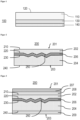
- FIG 1 shows a layered structure in the form of a display cover 100 according to the prior art.
- the display cover 100 consists of a transparent or translucent glass body 110, the surface 120 of which can be equipped with polymer functional layers, for example for shatter protection or optical anti-reflection coating. Underneath there is a polymer layer 130 and a transparent conductive layer 140 which serves as an electrode for a touch function.
- the surface 120 and internal interfaces are smooth.
- figure 2 shows a schematic structure of a layer structure 200 according to the invention.
- a zigzag-shaped layer c. 206 in the form of a polycarbonate layer sandwiched between two polycarbonate layers comprising layers a. 202 and layer b. 204 represent.
- the layer a. 202 points in the direction of the front or visible side 201 of the layered structure 200 and is thus aligned with a potential viewer.
- the layer b. 204 points in the direction of the inside 203 of a lighting system in which the layer structure 200 can be installed.
- the layer a. 202 forms an outer surface A 210 and a surface A' 220 angled to the surface A 210.
- the 204 forms an outer surface B 240 and a surface B' 230 angled to the surface B 240.
- the surfaces A 210 and B 240 are parallel to each other.
- Between layer a. 202 and layer b. 204 is the layer c in an angled form. 206 arranged.
- the layer c. 206 follows the contour formed by the surfaces A' 220 and B' 230 and forms a 3D structure 250 in the layer structure 200.
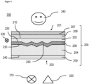
- figure 3 shows a schematic structure of a layer structure 200 according to the invention as shown in figure 2 is shown with the addition that on layer a. 202 as well as on layer b. 204 in each case a further layer 208 or 209 is attached.
- the layer 208 is a protective layer that protects the layer structure 200 from scratching or from the effects of chemicals.
- the layer 209 is either a protective layer that protects the layer structure 200 against scratching or the effects of chemicals, or a transparent electrode for the touch function.
- a layer 207 can be attached to at least one side of the layer structure 200 as an alternative or in addition to the layers 208 or 209 .
- the layer 207 is one or more layers selected from the group consisting of an anti-reflection layer, a low-reflection layer and an anti-fingerprint layer or a combination of at least two of these. In the figure 3 only the variant is shown that on the front, i.e. the side on which the layer a. is located, the additional layer 207 is arranged. However, any combination of layers 207, 208 and 209 is possible.
- FIG 4 shows a lighting system 300, which has a layer structure 200 according to the invention, as shown in figure 3 was described.
- the lighting system 300 has at least one light source 310 and/or a sensor 320 and at least one LED edge lighting 330 which couples light into the layer 202 .
- figure 5 shows four examples 5a, 5b, 5c, and 5d for different states of the lighting installation 300 according to the invention figure 4 , shown on one and the same layer structure 200.
- the display 310 and the layer structure 200 according to the invention are each shown schematically in cross section on the left and a photograph 400 of the front side or visible side 201 is shown on the right.
- a switched-off display 310 shown schematically as a rectangle
- the switched-off edge LED 390 are shown as the light source.
- Photo 400 shows a dark area, ie the black panel effect.
- state 5b the display 310 is off and the edge LED 390 (shown schematically as a lightbulb) is on.
- Photo 401 shows a 3D decorative surface in which the 3D structure 250 has been rendered visible to the viewer's eye.
- the display 310 is on and the edge LED 390 is on.
- the photo 402 shows a 3D decorative surface, with a 3D structure 250 made visible, which is illuminated by the light of the display 310 and is therefore outshined at the locations in the image area illuminated by the display 310 .
- the image of the display 310 appears free of distortion.
- state 5d the display 310 is on and the edge LED 390 is off.
- the photo 403 shows a dark area (black panel effect), which is only outshined in the image area of the display 310.
- the image of the display 310 appears free of distortion, without the 3D structure 380 being discernible.
- Transparent Makrolon® Ai from Covestro Deutschland AG: aromatic polycarbonate based on bisphenol A with an MVR of 19 cm 3 /(10 min), determined at 300° C. and 1.2 kg in accordance with DIN ISO 1133:2012-03 , containing UV absorbers and mold release agents.
- Ty measured at a thickness of 2 mm according to ISO 13468-2:2006 (D65, 10°): 88.07%.
- Haze determined according to ASTM D1003:2013 at a layer thickness of 2 mm: 0.68%.
- the polycarbonate was in the form of granules for injection molding. For pretreatment, the polycarbonate was dried in dry air at 120° C. for 4 hours. The polycarbonate has a refractive index of 1.585 according to ISO 489 (Method A).
- the intermediate layer c. was used: Makrofol ® LM 296 1-2 760125 from Covestro Deutschland AG: gray colored extruded film based on the polycarbonate Makrolon ® .
- the extruded film has a refractive index of 1.596 according to ISO 489 (Method A).
- the foils were each cut to the dimensions 200 mm ⁇ 150 mm with a thickness of 0.5 mm. They had a glossy surface on the 1st side and a very fine matted surface on their 2nd side.
- a metallic plate tool insert was provided with a 3D structure as shown in Figure B1.1.
- Figure B1.2 shows typical structure sizes of the individual elements of 7 to 16 mm and a height of the 3D structure elements of 0.49 mm. This results in an angle of 3.35° between the structural surface normal and the flat and smooth second wall of the injection mold.
- This structure is therefore suitable for producing layer structures according to the invention and for enabling experimental verification of the desired effects in layer structures according to the invention.
- Figure B1.1 3D model of a structure with pyramidal elements of different distribution on a plate with surface dimensions 200 mm x 150 mm.
- Figure B1.2 Dimensions of the pyramidal elements [mm]. Above: side view. Below: top view.
- injection-molded sample plates with a 3D structure on the back and dimensions of 200 mm ⁇ 150 mm ⁇ 3 mm were produced from polycarbonate compositions.
- the light transmission of the Makrofol ® film was 25% according to DIN ISO 13468-2:2006 (D65, 10°). This means it can be used as a black panel film.
- a multi-layer molded part measuring 200 mm ⁇ 150 mm ⁇ 6 mm was produced on an HM270 injection molding machine from Wittmann Battenfeld GmbH.
- a Makrofol ® film was placed as layer c., made of the material mentioned above, into that mold half of a steel mold with the mold inner dimensions 200 mm x 150 mm x 3 mm, the surface of which had the above-described and in Figure B1 .1 shown 3D structure was provided.
- the other half of the tool had a high-gloss finish.
- the transparent polycarbonate material melted at 305 °C was injected into the mold with a maximum specific injection pressure of approx. 2000 bar in order to layer a. to build.
- the film of layer c. was pressed into the structure of the mold surface during this overmolding. It didn't matter which side of the surface, i.e.
- the smooth side 1 or the rough side 2 was inserted to form the structure.
- the temperature of the mold wall was 90 °C on both sides, i.e. both on the ejector side and on the opposite injection side.
- the injection time was about 2.5 seconds.
- the tool was opened and the molded part was removed.
- the Makrolon layer forms layer a.; the Makrofol film layer c, hereinafter referred to as the polycarbonate sheet.
- the injection mold was then converted to the internal dimensions of 200 mm x 150 mm x 6 mm and the structured steel surface was removed so that both mold halves now had a high-gloss surface.
- the polycarbonate plate was preheated with the 3D structured side at 90° C. in a heating cabinet for 15 minutes. This plate was then placed back into the first mold half of the steel mold with the internal mold dimensions 200 x 150 x 6 mm, showing the structured surface with the respective foil to the second mold half. After the mold was closed, the transparent polycarbonate material, melted at 305 °C, was injected into the mold onto the polycarbonate sheet, on the side with the 3D structured film, with a maximum specific injection pressure of approx. 2000 bar.
- the temperature of the mold wall was 100 °C on the ejector side and 80 °C on the opposite injection side.
- the injection time was again 2.5 seconds.
- the tool was opened and the finished molded part with a total thickness of about 6 mm and two high-gloss sides was removed.
- the layer structure obtained now has a further layer b., and has the three-layer structure according to the invention with an internal 3D structure in the form of the structured “black panel film”.
- the light transmission of the layer structure obtained was 21% according to DIN ISO 13468-2:2006 (D65, 10°).
- the visual effects are characterized by the images figure 5 illustrated.
- layer a. and b. contained Makrolon ® as in Example 1, but for the intermediate layer c.
- the extruded film has a refractive index of 1.59 according to ISO 489 (method A).
- layer a. and b. contained Makrolon ® as in Example 2, but for the intermediate layer c. used: Makrofol® LM 296 1-2 from Covestro Deutschland AG: gray-colored extrusion film based on the polycarbonate Makrolon® and a transmission according to DIN ISO 13468-2:2006 (D65, 10°) of 75%.
- the extruded film has a refractive index of 1.59 according to ISO 489 (method A).
- the optical effects could be achieved to a large extent with this layer structure.
- the display image is even brighter, the 3D decor is subjectively even lower in contrast and the 3D structure is easily discernible in the ambient light (e.g. office room with indirect ceiling light).
- the display could be read clearly through the 3D structure no matter whether the edge light was on or not.
- the 3D structure was clearly visible with the edge light on.
- layer a. and b. contained Makrolon ® as in Example 1, but for the intermediate layer c. used: Makrofol ® LM 309 from Covestro Deutschland AG: 300 ⁇ m thick diffuser film based on the polycarbonate Makrolon ® , a transmission according to DIN ISO 13468-2:2006 (D65, 10°) of 86% and a half-power angle of 20° according to DIN 5036 :1978 related to light intensity.
- the visual evaluation was carried out as in the previous examples. All optical effects could also be displayed with this layer structure. Instead of the black panel effect, a so-called white panel effect appeared here: the diffuser film as layer c. scattered ambient light back to the observer. This structureless light in conjunction with wide scattering angles optically resolved the 3D structure and gave the observer the impression of a uniformly whitish bright surface. Because the level of the display panel was only about 4 mm behind the level of the diffuser, the display image still appeared sharp. The diffuser effect even improved image brightness when observing from an oblique position. With the white panel film, the 3D decor can be designed to be invisible in an ambient light environment when the edge lighting is switched off and made visible by edge lighting. The same applies to backlighting (display): they are invisible when switched off and visible when switched on.
Landscapes
- Laminated Bodies (AREA)
Abstract
Die Erfindung betrifft einen Schichtaufbau beinhaltend eine erste Schicht a. mit einer ersten planen Oberfläche A und einer der ersten Oberfläche A gegenüberliegenden, zumindest über einen Teilbereich gegenüber der ersten Oberfläche A angewinkelten Oberfläche A', wobei die Schicht a. ein transparentes Material aufweist, vorzugsweise Glas oder ein thermoplastisches Polymer, bevorzugt ausgewählt aus der Gruppe bestehend aus einem Polycarbonat, einem Copolycarbonat, Polyestercarbonat, PMMA, PET, einem Polyurethan, einem thermoplastischen Polyurethan oder einer Mischung aus mindestens zwei hiervon beinhaltet; eine weitere Schicht b. mit einer ersten planen Oberfläche B und einer der ersten Oberfläche B gegenüberliegenden, zumindest über einen Teilbereich gegenüber der ersten Oberfläche B angewinkelten Oberfläche B', wobei die Schicht b. ein transparentes Material aufweist, vorzugsweise Glas oder ein thermoplastisches Polymer, bevorzugt ausgewählt aus der Gruppe bestehend aus einem Polycarbonat, einem Copolycarbonat, Polyestercarbonat, PMMA, PET, einem Polyurethan, einem thermoplastischen Polyurethan oder einer Mischung aus mindestens zwei hiervon beinhaltet; wobei die Schichten a. und b. so zu einander angeordnet sind, dass die planen Oberflächen A und B parallel zueinander verlaufen und die angewinkelten Oberflächen A' und B' einander zugewandt sind und einen einander entsprechenden Verlauf der Winkelung unter Ausbildung einer 3-D Struktur aufweisen, und wobei eine Zwischenschicht c. zwischen der angewinkelten Oberfläche A' der ersten Schicht a. und der angewinkelten Oberfläche B' der weiteren Schicht b. so angeordnet ist, dass sie in ihrer Längsausdehnung dem angewinkelten Verlauf folgt und die 3-D Struktur abbildet, und wobei sich die Brechungsindices der Schichten b. und c. oder und der Schichten a. und c. jeweils um ≤ 0,1, bevorzugt um ≤ 0,05, mehr bevorzugt um ≤ 0,04, weiter bevorzugt um ≤ 0,03 unterscheiden, sowie dessen Herstellverfahren und eine Beleuchtungsanlage beinhaltend einen erfindungsgemäßen Schichtaufbau.The invention relates to a layer structure containing a first layer a. with a first planar surface A and a surface A′ opposite the first surface A and angled at least over a partial region relative to the first surface A, the layer a. comprises a transparent material, preferably glass or a thermoplastic polymer, preferably selected from the group consisting of a polycarbonate, a copolycarbonate, polyester carbonate, PMMA, PET, a polyurethane, a thermoplastic polyurethane or a mixture of at least two of these; another layer b. with a first planar surface B and a surface B' opposite the first surface B and angled at least over a partial region relative to the first surface B, the layer b. comprises a transparent material, preferably glass or a thermoplastic polymer, preferably selected from the group consisting of a polycarbonate, a copolycarbonate, polyester carbonate, PMMA, PET, a polyurethane, a thermoplastic polyurethane or a mixture of at least two of these; where the layers a. and b. are arranged relative to one another in such a way that the planar surfaces A and B run parallel to one another and the angled surfaces A' and B' face one another and have a corresponding course of the angling, forming a 3-D structure, and wherein an intermediate layer c. between the angled surface A' of the first layer a. and the angled surface B' of the further layer b. is arranged in such a way that it follows the angled course in its longitudinal extent and depicts the 3-D structure, and the refractive indices of the layers b. and c. or and the layers a. and c. each differ by ≦0.1, preferably by ≦0.05, more preferably by ≦0.04, more preferably by ≦0.03, as well as its production method and a lighting system containing a layer structure according to the invention.
Description
Die Erfindung betrifft einen Schichtaufbau, beinhaltend mindestens eine erste Schicht a. mit einer ersten planen Oberfläche A und einer zur Oberfläche A angewinkelt angeordneten Oberfläche A' und eine weitere Schicht b. mit einer planen Oberfläche B und einer zur Oberfläche B angewinkelten Oberfläche B', wobei die Schichten a. und b. so zu einander angeordnet sind, dass die planen Oberflächen A und B parallel zueinander verlaufen und die angewinkelten Oberflächen A' und B' einander zugewandt sind und einen einander entsprechenden Verlauf der Winkelung unter Ausbildung einer 3D- Struktur aufweisen, und wobei eine Zwischenschicht c. zwischen der gekrümmten Oberfläche A' der ersten Schicht a. und der gekrümmten Oberfläche B' der weiteren Schicht b. so angeordnet ist, dass sie in ihrer Längsausdehnung dem angewinkelten Verlauf folgt und die 3D-Struktur bildet, und wobei sich die Brechungsindices der Schichten b. und c. und der Schichten a. und c. jeweils um ≤ 0,1, bevorzugt um ≤ 0,05, mehr bevorzugt um ≤ 0,04, weiter bevorzugt um ≤ 0,03 unterscheiden.The invention relates to a layer structure containing at least one first layer a. with a first planar surface A and a surface A' arranged at an angle to the surface A and a further layer b. with a planar surface B and a surface B' angled to the surface B, wherein the layers a. and b. are arranged relative to one another in such a way that the planar surfaces A and B run parallel to one another and the angled surfaces A' and B' face one another and have a corresponding course of the angling, forming a 3D structure, and wherein an intermediate layer c. between the curved surface A' of the first layer a. and the curved surface B' of the further layer b. is arranged in such a way that it follows the angled course in its longitudinal extension and forms the 3D structure, and the refractive indices of the layers b. and c. and the layers a. and c. each differ by ≦0.1, preferably by ≦0.05, more preferably by ≦0.04, more preferably by ≦0.03.
Der erfindungsgemäße Schichtaufbau, der bevorzugt als dekorativer Mehrschichtkörper dient und im Folgenden auch als 3D-Dekor bezeichnet wird, wird bevorzugt mit einer Lichtquelle, auch Dekorlicht genannt, und einem Anzeigeelement zur Darstellung von Informationen kombiniert.The layer structure according to the invention, which preferably serves as a decorative multi-layer body and is also referred to below as a 3D decoration, is preferably combined with a light source, also referred to as a decorative light, and a display element for displaying information.
Der erfindungsgemäße Schichtaufbau umfasst einen Dekorlicht-Effekt mit zwei visuell unterschiedlichen Zuständen: In einem ersten Zustand wird die 3D-Struktur mittels einer Lichtquelle kontrastreich optisch sichtbar gemacht, während die 3D-Struktur in einem zweiten Zustand bei ambienter Lichtumgebung für das Auge unsichtbar bleibt und als gleichförmige Black Panel, Gray Panel oder White Panel Fläche erscheint.The layer structure according to the invention includes a decorative light effect with two visually different states: In a first state, the 3D structure is made optically visible by means of a light source with high contrast, while the 3D structure remains invisible to the eye in a second state in an ambient light environment and as a uniform black panel, gray panel, or white panel area appears.
Die Erfindung betrifft außerdem die Verwendung des erfindungsgemäßen Schichtaufbaus als Abdeckung für eine Mensch-Maschine-Kommunikationseinheit (englisch: Human Maschine Interface oder HMI).The invention also relates to the use of the layer structure according to the invention as a cover for a human-machine communication unit (Human Machine Interface or HMI).
Im Automobilbereich wird eine zunehmende Zahl an funktionellen Dekorblenden und Anzeigeelementen (Displays) verbaut, die den Insassen neben einer bestimmten Designsprache auch Informationen mitteilen sollen. Diese Anzeigeelemente teilen den Insassen Informationen durch die Lichtfarbe, den Ort der Beleuchtung oder durch ein zeitliches Beleuchtungsmuster (z.B. Blinken) mit. Wird ein Display hinter diesem Anzeige-Element verwendet, können Informationen auch in Form von Bildern und Text dargestellt werden. All diese Anzeige-Elemente werden meist durch eine transparente Kunststoffabdeckung geschützt, welche auch meist selbst ein bestimmtes geometrisches Design mit sich bringt. Diese Erfindung betrifft vor allem solche Kunststoffabdeckungen.In the automotive sector, an increasing number of functional decorative panels and display elements (displays) are installed, which are intended to provide the occupants with information in addition to a specific design language. These indicators communicate information to the occupants through the light color, the location of the lighting, or through a temporal lighting pattern (e.g. flashing). If a display is used behind this display element, information can also be presented in the form of images and text. All of these display elements are usually protected by a transparent plastic cover, which usually has a specific geometric design itself. This invention is particularly concerned with such plastic covers.
Abdeckungen für hinterleuchtete Anzeigeelemente mit transparentem Polycarbonat-Träger sind aus
Abdeckungen für Displays und Methoden zu deren Herstellung sind aus den Stand der Technik, z.B. aus
Kombinierte Leucht- und Anzeigeelemente mit gemeinsamer Abdeckscheibe sind aus
Das Leuchtelement kann ein zweites Anzeigeelement sein, das Symbole und 2D-gedruckte Dekore mittels Hinterleuchtung sichtbar machen kann. Die sog. Black Panel Abdeckung ist dadurch charakterisiert, dass sie solange schwarz erscheint und die rückseitigen Elemente in ambienter Umgebung optisch versteckt, bis eines der Elemente aktiviert wird, d.h. Licht aussendet. Vom Leuchtelement ausgesandtes Licht kann auch in den Bereich des Anzeigeelements reichen, so dass auch diese Fläche als Flächenlicht genutzt wird.The lighting element can be a second display element that can make symbols and 2D-printed decorations visible by means of backlighting. The so-called black panel cover is characterized by the fact that it appears black and optically hides the elements on the back in the ambient environment until one of the elements is activated, i.e. emits light. Light emitted by the lighting element can also reach into the area of the display element, so that this area is also used as area light.
Dreidimensional (3D), d.h. topografisch tief ausgeführte Kunststoff-Dekore sind bekannt. 3D-Dekore auf Basis von thermoplastischer Folie sind ebenso bekannt. So beschreibt
Der Stand der Technik weist keine Display-Abdeckungen auf, die im Anzeigefeld des Displays 3D-Strukturen oder 3D-Dekore tragen. 3D-Kunststoff-Dekore können nach dem Stand der Technik nicht als Display-Abdeckung verwendet werden, weil sie über die 3D-Oberfläche den Bildinhalt linsenartig optisch brechen und damit verzerren oder durch interne Totalreflexion ausblenden würden. In anderen Worten: Es können Elemente aus dem Stand der Technik nicht so miteinander kombiniert werden, ohne dass es im Bereich der Display-Anzeige zumindest partiell über die Anzeigefläche oder für bestimmte Blickrichtungen zu Bildverzerrungen oder -verzeichnungen oder Abschattungen kommt, oder dass das Sichtfeld eingeschränkt wird.The prior art does not have any display covers that carry 3D structures or 3D decorations in the display field of the display. According to the state of the art, 3D plastic decors cannot be used as a display cover because they optically break the image content over the 3D surface in a lens-like manner and thus distort it or hide it due to total internal reflection. In other words: elements from the prior art cannot be combined with one another in the area of the display without image distortions or distortions or shadowing occurring at least partially across the display area or for certain viewing directions, or without the field of vision being restricted becomes.
Eine erste Aufgabe war es daher, mindestens einen Nachteil aus dem SdT wenigstens zu einem Teil zu minimieren. Weiterhin war es eine Aufgabe der Erfindung eine Abdeckung, bspw. in Form eines Schichtaufbaus, für Displays, Sensoren und anderen möglichen Funktionselementen mit integrierter 3D-Struktur bereitzustellen, der sowohl die Darstellung der 3D-Struktur als auch die Anzeige eines hinter der Abdeckung, also dem Schichtaufbau, liegenden Displays ermöglicht. Des Weiteren war es eine Aufgabe eine Beleuchtungsanlage bereitzustellen, die es ermöglicht Anzeigeelemente (Displays), Funktionsleuchten und 3D-Dekorleuchten in geschlossene, dekorative thermoplastische Formteile zu integrieren. Insbesondere sollte eine Beleuchtungsanlage bereitgestellt werden, bspw. in Form eines kombinierten Leucht- und Anzeigemodul mit 3D-Struktur, das keine Verzerrungen des Bildes erzeugt, egal ob es frontal oder von der Seite beleuchtet wird. Weiterhin war es eine Aufgabe der Erfindung, ein kombiniertes Leucht- und Anzeigemodul mit 3D-Struktur bereitzustellen, das möglichst kompakt gebaut ist. Eine weitere Aufgabe war es ein kombiniertes Leucht- und Anzeigemodul mit 3D-Struktur bereitzustellen, das eine gemeinsame Abdeckscheibe für dahinter gruppierte Elemente aufweist und seine Dekorlicht- und Display-Funktionen lateral überlappen, so dass sie teilweise oder ganz die gleichen Flächen in der Abdeckscheibe nutzen, ohne dass es zu den oben beschriebenen funktionellen Einschränkungen kommt. Des Weiteren war es eine Aufgabe der Erfindung ein Verfahren zur Herstellung einer zuvor beschriebenen Abdeckscheibe, in Form eines Schichtaufbaus, bereit zu stellen.A first task was therefore to at least partially minimize at least one disadvantage from the SdT. Furthermore, it was an object of the invention to provide a cover, e.g the layered structure allows lying displays. Furthermore, it was an object to provide a lighting system that allows display elements (displays), functional lights and 3D decorative lights in closed, decorative thermoplastic to integrate moldings. In particular, a lighting system should be provided, e.g. in the form of a combined lighting and display module with a 3D structure, which does not distort the image, regardless of whether it is illuminated from the front or from the side. Furthermore, it was an object of the invention to provide a combined light and display module with a 3D structure that is built as compactly as possible. Another task was to provide a combined lighting and display module with a 3D structure that has a common cover panel for elements grouped behind it and its decorative light and display functions overlap laterally so that they partially or entirely use the same areas in the cover panel without the functional limitations described above. Furthermore, it was an object of the invention to provide a method for producing a cover pane as described above, in the form of a layered structure.
Überraschenderweise wurde ein mehrlagiger Schichtaufbau mit innenliegender 3D-Struktur gefunden, der als Abdeckung im Sinne der technischen Aufgabe verwendet werden kann.Surprisingly, a multi-layer structure with an internal 3D structure was found, which can be used as a cover in terms of the technical task.
Der erfindungsgemäße Schichtaufbau beinhaltet:
- a1. eine erste Schicht a. mit einer ersten planen Oberfläche A und einer der ersten Oberfläche A gegenüberliegenden, zumindest über einen Teilbereich gegenüber der ersten Oberfläche A angewinkelten Oberfläche A', wobei die Schicht a. ein transparentes Material aufweist, vorzugsweise Glas oder ein thermoplastisches Polymer, bevorzugt ausgewählt aus der Gruppe bestehend aus einem Polycarbonat, einem Copolycarbonat, Polyestercarbonat, PMMA, PET, einem Polyurethan, einem thermoplastischen Polyurethan oder einer Mischung aus mindestens zwei hiervon ;
- a2. eine weitere Schicht b. mit einer ersten planen Oberfläche B und einer der ersten Oberfläche B gegenüberliegenden, zumindest über einen Teilbereich gegenüber der ersten Oberfläche B angewinkelten Oberfläche B', wobei die Schicht b. ein transparentes Material aufweist, vorzugsweise Glas oder ein thermoplastisches Polymer, bevorzugt ausgewählt aus der Gruppe bestehend aus einem Polycarbonat, einem Copolycarbonat, Polyestercarbonat, PMMA, PET, einem Polyurethan, einem thermoplastischen Polyurethan oder einer Mischung aus mindestens zwei hiervon;
- wobei die Schichten a. und b. so zu einander angeordnet sind, dass die planen Oberflächen A und B parallel zueinander verlaufen und die angewinkelten Oberflächen A' und B' einander zugewandt sind und einen einander entsprechenden Verlauf der Winkelung unter Ausbildung einer 3D-Struktur aufweisen, und
- wobei eine Zwischenschicht c. zwischen der angewinkelten Oberfläche A' der ersten Schicht a. und der angewinkelten Oberfläche B' der weiteren Schicht b. so angeordnet ist, dass sie in ihrer Längsausdehnung dem angewinkelten Verlauf folgt und die 3D-Struktur abbildet, und
- wobei sich die Brechungsindices der Schichten b. und c. und der Schichten a. und c. jeweils um ≤ 0,1, bevorzugt um ≤ 0,05, mehr bevorzugt um ≤ 0,04, weiter bevorzugt um ≤ 0,03 unterscheiden.
- a1. a first layer a. with a first planar surface A and a surface A′ opposite the first surface A and angled at least over a partial region relative to the first surface A, the layer a. has a transparent material, preferably glass or a thermoplastic polymer, preferably selected from the group consisting of a polycarbonate, a copolycarbonate, polyester carbonate, PMMA, PET, a polyurethane, a thermoplastic polyurethane or a mixture of at least two thereof;
- a2. another layer b. with a first planar surface B and a surface B' opposite the first surface B and angled at least over a partial region relative to the first surface B, the layer b. has a transparent material, preferably glass or a thermoplastic polymer, preferably selected from the group consisting of a polycarbonate, a copolycarbonate, polyester carbonate, PMMA, PET, a polyurethane, a thermoplastic polyurethane or a mixture of at least two thereof;
- where the layers a. and b. are arranged in relation to one another in such a way that the planar surfaces A and B run parallel to one another and the angled surfaces A' and B' face one another and have a course of angulation corresponding to one another, forming a 3D structure, and
- wherein an intermediate layer c. between the angled surface A' of the first layer a. and the angled surface B' of the further layer b. is arranged in such a way that its longitudinal extent follows the angled course and depicts the 3D structure, and
- where the refractive indices of the layers b. and c. and the layers a. and c. each differ by ≦0.1, preferably by ≦0.05, more preferably by ≦0.04, more preferably by ≦0.03.
Bevorzugt fungiert die Schicht b. oder Schicht c. als Licht absorbierende sog. Black Panel Schicht, wobei die Schicht b. eine Lichttransmission von 10 bis 50%, bevorzugt von 15 bis 35%, mehr bevorzugt von 20 bis 25% aufweist, oder wobei Schicht c. eine Lichttransmission von 70 bis 92%, bevorzugt von 73 bis 85% und einen Halbwertswinkel für das gestreute Licht von 15 bis 50°, bevorzugt von 25 bis 50° aufweist und somit als Licht streuende sogenannte White Panel oder Grey Panel Schicht dient. Die Lichttransmission wird bestimmt nach DIN EN ISO 13468-2:2006-7.Layer b preferably functions. or layer c. as a light-absorbing so-called black panel layer, the layer b. has a light transmission of 10 to 50%, preferably 15 to 35%, more preferably 20 to 25%, or wherein layer c. has a light transmission of 70 to 92%, preferably from 73 to 85% and a half-value angle for the scattered light of 15 to 50°, preferably from 25 to 50° and thus serves as a light-scattering so-called white panel or gray panel layer. The light transmission is determined according to DIN EN ISO 13468-2:2006-7.
Weiterhin bevorzugt weist die Schicht b. oder Schicht c., besonders bevorzugt Schicht b. und Schicht c., eine Lichttransmission von 0 bis 95%, bevorzugt von 1 bis 92%, mehr bevorzugt von 10 bis 93% auf, bestimmt nach DIN EN ISO 13468-2:2006-7.Layer b. or layer c., particularly preferably layer b. and layer c., a light transmission of 0 to 95%, preferably 1 to 92%, more preferably 10 to 93%, determined according to DIN EN ISO 13468-2:2006-7.
Die erste Schicht a. und die weitere Schicht b. bilden bevorzugt jeweils eine Außenseite des Schichtaufbaus. Zusätzlich ist es bevorzugt, dass sich auf jeder dieser Außenseiten noch mindestens eine weitere Schicht oder mindestens eine Beschichtung befindet, wie später noch näher beschrieben.The first layer a. and the further layer b. each preferably form an outside of the layer structure. In addition, it is preferred that there is at least one further layer or at least one coating on each of these outer sides, as will be described in more detail later.
Die erste Schicht a. wird mit oder ohne weitere Beschichtung im Folgenden auch Vorderseite oder Sichtseite des Schichtaufbaus genannt. Die Vorderseite ist die Seite des Schichtaufbaus, die von einem Betrachter des in eine Beleuchtungsanlage eingebauten Schichtaufbaus gesehen wird. Das ist folglich die Seite, von der aus ein Betrachter das 3D-Dekor sehen soll und kann, wenn es entsprechend beleuchtet wird. Die Innenseite bzw. Rückseite des Schichtaufbaus ist die Seite, die zu möglichen Anzeige-Elementen bzw. einer rückseitigen Beleuchtung gerichtet ist und die von der weiteren Schicht b. mit oder ohne weitere Beschichtung gebildet wird.The first layer a. is also referred to below as the front or visible side of the layer structure, with or without further coating. The front side is the side of the sandwich that is seen by a viewer of the sandwich built into a lighting fixture. This is thus the side from which a viewer should and can view the 3D decoration when appropriately illuminated. The inside or back of the layer structure is the side that faces possible display elements or backlighting and that from the further layer b. is formed with or without further coating.
Unter parallel wird im Rahmen der vorliegenden Erfindung eine Abweichung der Oberflächen A zu B vyon weniger als 5°, bevorzugt von weniger als 3° verstanden.In the context of the present invention, parallel means a deviation of the surfaces A from B by less than 5°, preferably less than 3°.
Unter angewinkelt angeordneten Oberflächen A' bzw. B' wird im Rahmen der vorliegenden Erfindung verstanden, dass die Oberflächen A' bzw. B' gegen über den parallel zueinander verlaufenden Oberflächen A bzw. B der Schichten a. bzw. b. mindestens an einer Stelle nicht koplanar zueinander verlaufen, sodass ihre Flächenelemente einen Winkel von bis zu 85° einschließen können. Bevorzugt liegt die Anwinkelung der Oberfläche A' zu der Oberfläche A und die Anwinkelung der Oberfläche B' zu der Oberfläche B in einem Bereich von 2 bis 85°, weiter bevorzugt in einem Bereich von 3 bis 45°, besonders bevorzugt in einem Bereich von 3 bis 30°.In the context of the present invention, surfaces A′ or B′ arranged at an angle mean that the surfaces A′ or B′ are opposite to the surfaces A or B of the layers a. or b. at least at one point they are not coplanar with one another, so that their surface elements can enclose an angle of up to 85°. The angling of surface A' to surface A and the angling of surface B' to surface B is preferably in a range from 2 to 85°, more preferably in a range from 3 to 45°, particularly preferably in a range of 3 up to 30°.
Der Teilbereich in dem die Oberfläche A' gegenüber der Oberfläche A angewinkelt ist, beträgt bevorzugt 10 bis 99 %, weiter bevorzugt 15 bis 95 %, besonders bevorzugt 20 bis 95 %, bezogen auf die Gesamtfläche der Oberfläche A'.The portion in which surface A' is angled relative to surface A is preferably 10 to 99%, more preferably 15 to 95%, particularly preferably 20 to 95%, based on the total area of surface A'.
Der Teilbereich in dem die Oberfläche B' gegenüber der Oberfläche B angewinkelt ist, beträgt bevorzugt 10 bis 99 %, weiter bevorzugt 15 bis 95 %, besonders bevorzugt 20 bis 95 %, bezogen auf die Gesamtfläche der Oberfläche B'.The portion in which surface B' is angled relative to surface B is preferably 10 to 99%, more preferably 15 to 95%, particularly preferably 20 to 95%, based on the total area of surface B'.
Bevorzugt verlaufen die Flächenelemente der Oberflächen A' und B' nahezu parallel zu einander, sodass sich eine regelmäßige 3D-Struktur ausbildet.The surface elements of the surfaces A′ and B′ preferably run almost parallel to one another, so that a regular 3D structure is formed.
Unter nahezu parallel wird eine Abweichung der Oberflächen A' zu B' von weniger als 5°, bevorzugt von weniger als 3° und besonders bevorzugt von weniger als 1° verstanden.Almost parallel means a deviation of the surfaces A′ from B′ of less than 5°, preferably less than 3° and particularly preferably less than 1°.
Bei der 3D-Struktur kann es sich um jegliche Form handeln, die der Fachmann hierfür auswählen würde. Bevorzugt handelt es sich um 3D-Strukturen ausgewählt aus der Gruppe bestehend aus zickzackförmig, wellenförmig, insbesondere sinusförmig oder Kombinationen aus mindestens zwei hiervon.The 3D structure can be any shape one skilled in the art would choose. The 3D structures are preferably selected from the group consisting of zigzag, wavy, in particular sinusoidal, or combinations of at least two of these.
Handelt es sich um eine wellenförmige 3D-Struktur so bildet die Tangente an jeder Stelle der Oberfläche A' bzw. B' gegenüber der Oberfläche A bzw. B den Bezugspunkt für die angegebenen Winkel der Anwinkelung.If it is a wavy 3D structure, the tangent at each point of the surface A' or B' opposite the surface A or B forms the reference point for the specified angle of angling.
Bevorzugt weist die Schicht a. eine Dicke in einem Bereich von 100 µm bis 7 mm, bevorzugt in einem Bereich von 150 µm bis 5 mm, besonders bevorzugt in einem Bereich von 200 µm bis 2 mm auf. Bevorzugt weist die Schicht a. eine Dickenabweichung über ihre gesamte Flächenausdehnung von weniger als 20 %, bevorzugt weniger als 10 %, besonders bevorzugt von weniger als 5 % auf.The layer a. a thickness in a range from 100 μm to 7 mm, preferably in a range from 150 μm to 5 mm, particularly preferably in a range from 200 μm to 2 mm. The layer a. a thickness deviation over their entire surface area of less than 20%, preferably less than 10%, particularly preferably less than 5%.
Bevorzugt weist die Schicht b. eine Dicke in einem Bereich von 100 µm bis 7 mm, bevorzugt in einem Bereich von 150 µm bis 5 mm, besonders bevorzugt in einem Bereich von 200 µm bis 2 mm auf. Bevorzugt weist die Schicht b. eine Dickenabweichung über ihre gesamte Flächenausdehnung von weniger als 20 %, bevorzugt weniger als 10 %, besonders bevorzugt von weniger als 5 % auf.The layer b. a thickness in a range from 100 μm to 7 mm, preferably in a range from 150 μm to 5 mm, particularly preferably in a range from 200 μm to 2 mm. The layer b. a thickness deviation over their entire surface area of less than 20%, preferably less than 10%, particularly preferably less than 5%.
Bevorzugt weist die Schicht c. eine Dicke in einem Bereich von 10 bis 1000 µm, bevorzugt in einem Bereich von 50 bis 750 µm, besonders bevorzugt von 125 bis 600 µm, ganz besonders bevorzugt von 250 bis 500 µm, am meisten bevorzugt von 300 bis 400 µm auf. Bevorzugt weist die Schicht c. eine Dickenabweichung über ihre gesamte Flächenausdehnung von weniger als 20 %, bevorzugt weniger als 10 %, besonders bevorzugt von weniger als 5 % auf.The layer c. a thickness in a range from 10 to 1000 μm, preferably in a range from 50 to 750 μm, particularly preferably from 125 to 600 μm, very particularly preferably from 250 to 500 μm, most preferably from 300 to 400 μm. The layer c. a thickness deviation over their entire surface area of less than 20%, preferably less than 10%, particularly preferably less than 5%.
Bevorzugt weist der Schichtaufbau eine Dicke in einem Bereich von 350 µm bis 10 mm, besonders bevorzugt in einem Bereich von 2 bis 6 mm auf. Bevorzugt weist der Schichtaufbau eine Dickenabweichung über seine gesamte Flächenausdehnung von weniger als 20 %, bevorzugt weniger als 10 %, besonders bevorzugt von weniger als 5 % auf.The layer structure preferably has a thickness in a range from 350 μm to 10 mm, particularly preferably in a range from 2 to 6 mm. The layer structure preferably has a thickness deviation of less than 20%, preferably less than 10%, particularly preferably less than 5%, over its entire surface area.
Aufgrund der Abwinkelung der Oberflächen A' und B' weist die aus der Schicht c. gebildete 3D-Struktur bevorzugt eine Tiefenausdehnung innerhalb des Schichtaufbaus, die sich senkrecht zu den parallel ausgebildeten Oberflächen A und B der Schichten a. und b. erstreckt, in einem Bereich von 100 bis 1000 µm, mehr bevorzugt in einem Bereich von 150 bis 800 µm, besonders bevorzugt in einem Bereich von 200 bis 500 µm.Due to the angling of the surfaces A' and B', the layer c. formed 3D structure prefers a depth extension within the layer structure, which is perpendicular to the parallel surfaces A and B of the layers a. and b. extends, in an area of 100 to 1000 µm, more preferably in a range from 150 to 800 µm, particularly preferably in a range from 200 to 500 µm.
Die Schichten a., b. oder c. weisen jeweils unabhängig voneinander bevorzugt eine Flächenausdehnung in einem Bereich von 1 cm2 bis 10 m2, mehr bevorzugt in einem Bereich von 10 cm2 bis 5 m2, besonders bevorzugt in einem Bereich von 100 cm2 bis 1 m2 auf.The layers a., b. or c. each independently of one another preferably have a surface area in a range from 1 cm 2 to 10 m 2 , more preferably in a range from 10 cm 2 to 5 m 2 , particularly preferably in a range from 100 cm 2 to 1 m 2 .
In einer bevorzugten Ausführungsform des Schichtaufbaus weist dieser bevorzugt eine, weiter bevorzugt zwei, besonders bevorzugt drei, ganz besonders bevorzugt vier der folgenden Merkmale auf, wobei die Merkmale (E4) und (E5) alternativ gewählt werden also nicht gemeinsam verwirklicht sind, jeweils aber mit allen anderen Merkmalen frei kombinierbar sind:
- (E1) Die Oberfläche A der Vorderseite, also der Außenfläche der Schicht a. und die Oberfläche B der Rückseite, also der Außenseite von Schicht b. sind glatt. Unter glatt wird verstanden, dass die Oberflächen A und B keine Stufen größer als 0,1 mm und keine Krümmungsradien kleiner als 10 mm aufweisen; weiterhin bevorzugt ist, dass die Oberflächen A und B eine Rautiefe Rz nach DIN EN ISO 4287 (10/98) von maximal 50 µm, bevorzugt von maximal 10 µm aufweisen.
- (E2) die Schicht a. ist transparent. Unter transparent wird verstanden, dass die Schicht a. im sichtbaren Licht-Spektrum teil- oder volltransparent ist, bevorzugt einen totalen Lichttransmissionsgrad von > 70%, bevorzugt von >80%, mehr bevorzugt von > 85% bestimmt nach DIN EN ISO 13468-2:2006-7. Bevorzugt weist die Schicht a. eine spektrale Absorption nur außerhalb der Emissionsspektren von Display und Ambiente-/Dekorlicht auf.
- (E3) die Schicht a. ist bevorzugt als ein flächiger Lichtleiter ausgebildet. Unter Lichtleiter im Zusammenhang mit Schicht a. wird verstanden, dass Licht, z.B. weißes oder farbiges LED-Licht, über eine oder mehrere seiner Kanten eingekoppelt werden kann und das Licht mit ausreichend geringer optischer Dämpfung in der Schicht a. propagieren kann.
- (E4) mindestens eine der Schichten b. oder c., bevorzugt Schicht b. und Schicht c., weist einen Absorptionsbereich im sichtbaren Spektrum auf. Beispiele sind transparent farbig und transparent Neutraldichte-grau. Unter Absorptionsbereich wird verstanden, dass die Schicht b. bzw. c. eine Lichttransmission von 5 bis 90%, bevorzugt von 8 bis 70%, mehr bevorzugt von 10 bis 50%, besonders bevorzugt von 15 bis 35%, ganz besonders bevorzugt von 20 bis 25% aufweist, bestimmt nach DIN EN ISO 13468-2:2006-7.
- (E5) die Schicht c. als Licht streuende Schicht dient, gekennzeichnet durch eine Lichttransmission von 70 bis 92%, bevorzugt von 73 bis 85% und einen Halbwertswinkel für das gestreute Licht von 15 bis 50°, bevorzugt von 25 bis 50°.
- (E1) The surface A of the front side, ie the outer surface of the layer a. and the surface B of the back, ie the outside of layer b. are smooth. By smooth is meant that the surfaces A and B have no steps greater than 0.1 mm and no radii of curvature less than 10 mm; It is further preferred that the surfaces A and B have a peak-to-valley height Rz according to DIN EN ISO 4287 (10/98) of at most 50 μm, preferably at most 10 μm.
- (E2) the layer a. is transparent. By transparent is meant that the layer a. is partially or fully transparent in the visible light spectrum, preferably a total light transmittance of >70%, preferably >80%, more preferably >85% determined according to DIN EN ISO 13468-2:2006-7. The layer a. spectral absorption only outside the emission spectra of the display and ambient/decor light.
- (E3) the layer a. is preferably designed as a flat light guide. Under light guides related to layer a. it is understood that light, for example white or colored LED light, can be coupled in via one or more of its edges and the light with sufficiently low optical attenuation in layer a. can propagate.
- (E4) at least one of the layers b. or c., preferably layer b. and layer c., has an absorption range in the visible spectrum. Examples are transparent colored and transparent neutral density gray. By absorption range is meant that the layer b. or c. has a light transmission of 5 to 90%, preferably 8 to 70%, more preferably 10 to 50%, particularly preferably 15 to 35%, very particularly preferably 20 to 25%, determined according to DIN EN ISO 13468-2: 2006-7.
- (E5) the layer c. serves as a light-scattering layer, characterized by a light transmission of 70 to 92%, preferably 73 to 85% and a half-value angle for the scattered light of 15 to 50°, preferably 25 to 50°.
Bevorzugt weist der Schichtaufbau eine Eigenschaft oder Eigenschaftskombination ausgewählt aus der Gruppe bestehend aus (E1); (E2); (E3); (E4); (E5); (E1) und (E2); (E1) und (E3); (E1) und (E4); (E1) und (E5); (E2) und (E3); (E2) und (E4); (E2) und (E5); (E3) und (E4); (E3) und (E5); (E1) und (E2) und (E3); (E1) und (E2) und (E4); (E1) und (E2) und (E5); (E1) und (E3) und (E4); (E1) und (E3) und (E5); (E2) und (E3) und (E4); (E2) und (E3) und (E5); (E1) und (E2) und (E3) und (E4), (E1) und (E2) und (E3) und (E5); besonders bevorzugt (E1) und (E2) und (E3) oder (E2) und (E3) und (E4) oder (E1) und (E2) und (E3) und (E4) oder (E1) und (E2) und (E3) und (E5) auf.The layer structure preferably has a property or combination of properties selected from the group consisting of (E1); (E2); (E3); (E4); (E5); (E1) and (E2); (E1) and (E3); (E1) and (E4); (E1) and (E5); (E2) and (E3); (E2) and (E4); (E2) and (E5); (E3) and (E4); (E3) and (E5); (E1) and (E2) and (E3); (E1) and (E2) and (E4); (E1) and (E2) and (E5); (E1) and (E3) and (E4); (E1) and (E3) and (E5); (E2) and (E3) and (E4); (E2) and (E3) and (E5); (E1) and (E2) and (E3) and (E4), (E1) and (E2) and (E3) and (E5); particularly preferably (E1) and (E2) and (E3) or (E2) and (E3) and (E4) or (E1) and (E2) and (E3) and (E4) or (E1) and (E2) and (E3) and (E5) on.
Mindestens eine, bevorzugt alle der Schichten b., oder c. weisen eine Lichttransmission von 5 bis 95%, bevorzugt von 7 bis 93%, mehr bevorzugt von 10 bis 92%, bestimmt nach DIN EN ISO 13468-2:2006-7 auf. Insbesondere Schicht c. weist eine Lichttransmission von 5 bis 95%, bevorzugt von 7 bis 93%, mehr bevorzugt von 10 bis 92%, bestimmt nach DIN EN ISO 13468-2:2006-7 auf.At least one, preferably all of the layers b., or c. have a light transmission of 5 to 95%, preferably 7 to 93%, more preferably 10 to 92%, determined according to DIN EN ISO 13468-2:2006-7. In particular layer c. has a light transmission of 5 to 95%, preferably 7 to 93%, more preferably 10 to 92%, determined according to DIN EN ISO 13468-2:2006-7.
In dem Absorptionsbereich, wie in (E4) genannt, gilt bevorzugt, dass bei einer Lichttransmission von 5 bis 60% bevorzugt ein Halbwertswinkel von 0 bis 30° für das gestreute Licht besteht. Weiter bevorzugt ist bei einer Lichttransmission von 60 bis 85% ein Halbwertswinkel für das gestreute Licht von 15 bis 50°, bevorzugt von 25 bis 50° besteht.In the absorption range, as mentioned in (E4), it is preferred that with a light transmission of 5 to 60%, there is preferably a half-value angle of 0 to 30° for the scattered light. More preferably, with a light transmission of 60 to 85%, there is a half-value angle for the scattered light of 15 to 50°, preferably of 25 to 50°.
Bevorzugt weist der Schichtaufbau die folgenden Merkmale auf:
- (E1) die Oberfläche A der Vorderseite, also der Außenfläche der Schicht a. und die Oberfläche B der Rückseite, also der Außenseite von Schicht b. sind glatt;
- (E2) die Schicht a. ist transparent;
- (E3) optional, die Schicht a. ist als ein flächiger Lichtleiter ausgebildet;
- (E4) mindestens eine der Schichten b. oder c. weist einen Absorptionsbereich im sichtbaren Spektrum auf.
- (E1) the surface A of the front side, ie the outer surface of layer a. and the surface B of the back, ie the outside of layer b. are smooth;
- (E2) the layer a. is transparent;
- (E3) optionally, the layer a. is designed as a flat light guide;
- (E4) at least one of the layers b. or c. has an absorption range in the visible spectrum.
Bevorzugt weist der Schichtaufbaus das folgende Merkmal auf:
(E4) mindestens eine der Schichten b. oder c. weist einen Absorptionsbereich im sichtbaren Spektrum auf.The layer structure preferably has the following feature:
(E4) at least one of the layers b. or c. has an absorption range in the visible spectrum.
In einer bevorzugten Ausführungsform des Schichtaufbaus weist dieser das folgende Merkmal auf:
(E5) die Schicht c. ist als Licht streuende Schicht ausgebildet, insbesondere durch eine Lichttransmission von 70 bis 92%, bevorzugt von 73 bis 85% und einen Halbwertswinkel für das gestreute Licht von 15 bis 50°, bevorzugt von 25 bis 50°.In a preferred embodiment of the layer structure, this has the following feature:
(E5) the layer c. is designed as a light-scattering layer, in particular with a light transmission of 70 to 92%, preferably 73 to 85% and a half-value angle for the scattered light of 15 to 50°, preferably 25 to 50°.
Die Schicht c. ist im Bereich des sichtbaren Lichts brechungsindexangepasst zu den Schichten a. und b.. Hierdurch ist die 3D-Struktur in ambienter Lichtumgebung und im ausgeschalteten Zustand aller künstlichen Lichtquellen, Hinterleuchtungslicht und LED-Kantenlicht, unsichtbar gemacht. Unter brechungsindexangepasst wird verstanden, dass sich die Brechungsindices D der Schichten b. und c. und der Schichten a. und c. jeweils um ≤ 0,1, bevorzugt um ≤ 0,05, mehr bevorzugt um ≤ 0,04, weiter bevorzugt um ≤ 0,03 unterscheiden. Der Brechungsindex D ist definiert als Wert für das Verhältnis der Lichtgeschwindigkeit im Vakuum zur Lichtgeschwindigkeit im Medium (Schicht) und bezieht sich auf die Natrium-D-Linie bei der Wellenlänge 589 nm, zugleich die Standardwellenlänge bei Refraktometern. Wenn nicht anders angegeben wurde er gemäß ISO 489 (Verfahren A) ermittelt.The layer c. is refractive index matched to the layers a. and b.. This makes the 3D structure invisible in the ambient light environment and when all artificial light sources, backlighting and LED edge lights are switched off. By refractive index matched is meant that the refractive indices D of the layers b. and c. and the layers a. and c. in each case by ≦0.1, preferably by ≦0.05, more preferably by ≦0.04 preferably differ by ≤ 0.03. The refractive index D is defined as the ratio of the speed of light in a vacuum to the speed of light in the medium (layer) and refers to the sodium D line at the wavelength of 589 nm, which is also the standard wavelength for refractometers. Unless otherwise stated, it was determined according to ISO 489 (Method A).
Die Schichten a. und b. weisen bevorzugt ein thermoplastisches Material auf oder bestehen daraus. Bevorzugt weist Schicht c. ebenfalls ein thermoplastisches Material auf.The layers a. and b. preferably have or consist of a thermoplastic material. Layer c. also a thermoplastic material.
Das thermoplastische Material ist bevorzugt ausgewählt aus der Gruppe bestehend aus aromatischem Polycarbonat (PC), einschließlich Copolycarbonat, Polyestercarbonat, Polystyrol (PS), Styrol-Copolymeren wie z.B. transparentes Polystyrolacrylnitril (PSAN), Polyalkylenen wie Polyethylen (PE) und Polypropylen (PP), aromatischem Polyester wie Polyethylenterephthalat (PET) und Polybutylenterephthalat (PBT), PET-Cyclohexandimethanol-Copolymer (PETG), Polyethylennaphthalat (PEN), Polyphenylenether (PPE), Polyacrylat, Copolyacrylat, insbesondere Poly- oder Copolymethylmethacrylaten wie Polymethylmethacrylat (PMMA), Polyimide (z.B. PMMI), amorphen Polyamiden (PA), Polyethersulfonen, thermoplastischen Polyurethanen, cyclischen Olefinpolymeren oder -copolymeren (COP bzw. COC) oder eine Mischungen mindestens zweier der genannten Komponenten. Bevorzugt ist das thermoplastische Material transparent. Bevorzugt basier das thermoplastische Material auf aromatischem Polycarbonat und/oder Polymethylmethacrylat, besonders bevorzugt auf aromatischem Polycarbonat oder besteht daraus.The thermoplastic material is preferably selected from the group consisting of aromatic polycarbonate (PC), including copolycarbonate, polyester carbonate, polystyrene (PS), styrene copolymers such as transparent polystyrene acrylonitrile (PSAN), polyalkylenes such as polyethylene (PE) and polypropylene (PP), aromatic polyesters such as polyethylene terephthalate (PET) and polybutylene terephthalate (PBT), PET-cyclohexanedimethanol copolymer (PETG), polyethylene naphthalate (PEN), polyphenylene ether (PPE), polyacrylate, copolyacrylate, in particular poly- or copolymethyl methacrylates such as polymethyl methacrylate (PMMA), polyimides (e.g. PMMI), amorphous polyamides (PA), polyethersulfones, thermoplastic polyurethanes, cyclic olefin polymers or copolymers (COP or COC) or a mixture of at least two of the components mentioned. The thermoplastic material is preferably transparent. The thermoplastic material is preferably based on aromatic polycarbonate and/or polymethyl methacrylate, particularly preferably on aromatic polycarbonate or consists of it.
Beispiele für bevorzugte thermoplastischen Polymere, insbesondere in Form von thermoplastischen Polymeren werden im Zusammenhang mit dem weiter unten beschriebenen erfindungsgemäßen Verfahren zur Herstellung eines Schichtaufbaus genannt, weshalb an dieser Stelle auf deren Beschreibung verwiesen wird. Alle im Zusammenhang mit dem erfindungsgemäßen Verfahren beschriebenen thermoplastischen Materialien, deren Zusammensetzungen, inklusive Mengenverhältnissen, Herstellung und Eigenschaften sind ebenfalls für die entsprechenden Schichten a., b. und c. des erfindungsgemäßen Schichtaufbaus gültig.Examples of preferred thermoplastic polymers, in particular in the form of thermoplastic polymers, are mentioned in connection with the method according to the invention, described further below, for producing a layer structure, which is why reference is made at this point to their description. All thermoplastic materials described in connection with the method according to the invention, their compositions, including quantitative ratios, production and properties are also for the corresponding layers a., b. and c. of the layer structure according to the invention.
Alternativ weist mindestens eine der Schichten a. oder b. ein Glas, ausgewählt aus der Gruppe bestehend aus einem Quarzglas, einem Borsilikatglas, einem Fluorsilikatglas, einem Fluoridglas, einem Borphosphatglat, einem Bleiglas, einem Alumosilikatglas oder einer Kombination aus mindestens zwei hiervon, auf.Alternatively, at least one of the layers a. or b. a glass selected from the group consisting of a quartz glass, a borosilicate glass, a fluorosilicate glass, a fluoride glass, a boron phosphate glass, a lead glass, an aluminosilicate glass or a combination of at least two of these.
In einer bevorzugten Ausführungsform des Schichtaufbaus ist die weitere Schicht c. blasenfrei mit den Schichten a. und b. verbunden. Blasenfrei gemäß der Erfindung beutet, dass keine Blasen mit bloßem Auge, bevorzugt bei einer 20-fachen Vergrößerung zu erkennen sind.In a preferred embodiment of the layer structure, the further layer c. bubble-free with the layers a. and b. tied together. Bubble-free according to the invention means that no bubbles can be seen with the naked eye, preferably at a magnification of 20x.
In einer bevorzugten Ausführungsform des Schichtaufbaus beinhaltet die weitere Schicht c. ein transparentes, thermoplastisches Polymer, bevorzugt ausgewählt aus der Gruppe bestehend aus einem Polycarbonat, einem Copolycarbonat, einem Polymethylmethacrylat (PMMA), einem Polyethylenterephthalat (PET), einem Blend beinhaltend mindestens eines der vorstehenden Polymere oder einer Mischung aus mindestens zwei hiervon.In a preferred embodiment of the layer structure, the further layer c. a transparent, thermoplastic polymer, preferably selected from the group consisting of a polycarbonate, a copolycarbonate, a polymethyl methacrylate (PMMA), a Polyethylene terephthalate (PET), a blend containing at least one of the above polymers or a mixture of at least two thereof.
Die Schicht c, ist bevorzugt eine technische Folie oder eine Beschichtung, während die beiden äußeren Schichten a. und b. bevorzugt aus einem thermoplastischen Kunststoff bestehen, der mittels eines Spritzguss- oder Direktbeschichtungsverfahrens (engl.: Direct Coating, Direct Skinning) hergestellt werden kann. Diese Schicht c. dient dazu, ein Dekor durch ihre Verformung (sog. 3D-Dekor) darzustellen oder aber gleichzeitig ein Dekor oder ein oder mehrere Symbole und Text durch weitere Veredelungsschritte wie das Bedrucken darzustellen (sog. 2D-Dekore).The layer c is preferably a technical film or a coating, while the two outer layers a. and b. preferably consist of a thermoplastic material which can be produced by means of an injection molding or direct coating process (engl.: Direct Coating, Direct Skinning). This layer c. serves to represent a decor through its deformation (so-called 3D decor) or at the same time to represent a decor or one or more symbols and text through further finishing steps such as printing (so-called 2D decors).
Die Schicht c. ist bevorzugt eine thermoplastische Folie, bevorzugt bestehend aus Polycarbonat. Alternativ kann die Schicht c. eine der folgenden Materialien beinhalten oder daraus bestehen: PMMA, PET. Beispiele: Makrofol® LM Polycarbonat Black Panel Folie, Makrofol® LM Polycarbonat Diffusorfolie (Hersteller: Covestro AG, Deutschland), Hostaphan® WNL transluzentweiße Polyesterfolie für Laminieranwendungen, Hostaphan® YNK gelbe Polyesterfolie (Hersteller: Mitsubishi Polyester Film GmbH, Deutschland), PLEXIGLAS® Folien in transparent blau, gelb, grün, rot, orange und braun (Hersteller: Röhm GmbH, Deutschland).The layer c. is preferably a thermoplastic film, preferably consisting of polycarbonate. Alternatively, layer c. contain or consist of one of the following materials: PMMA, PET. Examples: Makrofol ® LM polycarbonate black panel film, Makrofol ® LM polycarbonate diffuser film (manufacturer: Covestro AG, Germany), Hostaphan ® WNL translucent white polyester film for laminating applications, Hostaphan ® YNK yellow polyester film (manufacturer: Mitsubishi Polyester Film GmbH, Germany), PLEXIGLAS ® Foils in transparent blue, yellow, green, red, orange and brown (manufacturer: Röhm GmbH, Germany).
Bevorzugt wird die Schicht c. mittels Laserstrukturierung, Tintenstrahldruck, Laserdruck, Digitaldruck, Offset-Druck oder Siebdruck mit optischer Information versehen. Verschiedene Drucktechnologien bieten unterschiedliche Vorteile: Der Siebdruck ist das am häufigsten für Polycarbonat-Folien angewandte Druckverfahren, bei dem direkt auf das Medium gedruckt wird. Der Siebdruck ergibt haltbare, langlebige Druckbilder mit hoher Opazität und Farbdichte. Der Offset-Druck eignet sich wegen der hohen Druckgeschwindigkeit besonders zur wirtschaftlichen Produktion großer Auflagen und für die Erzeugung sehr feiner Linienmuster. Der Digitaldruck ermöglicht schließlich vollkommene Flexibilität bei hoher Geschwindigkeit und Volumen, da keine Druckform oder -platte benötigt wird und die Technologie für den Druck nach Bedarf bis hinab zu Einzelauflagen verwendet werden kann.Layer c is preferred. provided with optical information by means of laser structuring, inkjet printing, laser printing, digital printing, offset printing or screen printing. Different printing technologies offer different advantages: Screen printing is the most common printing process for polycarbonate films, where printing is done directly onto the medium. Screen printing produces durable, long-lasting printed images with high opacity and color density. Due to the high printing speed, offset printing is particularly suitable for the economical production of large runs and for the creation of very fine line patterns. Finally, digital printing allows for complete flexibility at high speed and volume as no printing forme or plate is required and the technology can be used to print on demand down to single runs.
Bevorzugt weisen die Schichten a. und b. das gleiche Material auf. Weiterhin bevorzugt weisen alle drei Schichten a., b. und c. das gleiche Material auf. Bevorzugt ist das Material der Schicht a. und b. ein Polycarbonat. Bevorzugt ist das Material der Schicht a., b. und c. ein Polycarbonat. Bevorzugt ist das Material der Schicht a., b und c. ein PMMA. Weiterhin bevorzugt ist das Material der Schicht a., b und c. ein Polyamid.The layers a. and b. the same material. Furthermore, all three layers a., b. and c. the same material. The material of layer a is preferred. and b. a polycarbonate. The material of layer a., b. and c. a polycarbonate. The material of layers a., b and c is preferred. a PMMA. The material of layers a., b and c is also preferred. a polyamide.
In einer bevorzugten Ausführungsform des Schichtaufbaus weist die Schicht a. mindestens eine, bevorzugt mindestens zwei, weiter bevorzugt mindestens drei, besonders bevorzugt mindestens vier, mehr bevorzugt mindestens fünf, am meisten bevorzugt alle der folgenden Eigenschaften auf:
- a1. eine Dicke in
einem Bereich von 100 µm bis 7 mm, bevorzugt von 150 µm bis 5 mm, besonders bevorzugtvon 200µm bis 2 mm; - a2. eine Fläche in einem Bereich von 1 cm2 bis 10 m2, bevorzugt von 10 cm2 bis 5 m2, besonders bevorzugt
von 100 cm2 bis 1 m2; - a3. eine Ausdehnung der gewinkelten Struktur quer zur Flächenausdehnung der Schicht a. in einem Bereich von 10 µm bis 1 cm, bevorzugt in einem Bereich von 20 µm bis 1000 µm, weiter bevorzugt in einem Bereich von 50 bis 500 µm;
- a4. eine Rautiefe Rz auf der Oberfläche A nach DIN EN ISO 4287 (10/98) von maximal 50 µm, mehr bevorzugt von maximal 30 µm, besonders bevorzugt von maximal 10 µm;
- a5. eine Transparenz von >70%, bevorzugt von >80%, besonders bevorzugt von >85%, bestimmt nach DIN EN ISO 13468-2-2006-7;
- a6. frei von Lichtstreuung im sichtbaren Spektralbereich, insbesondere frei von lichtstreuenden Partikeln.
- a1. a thickness in a range from 100 μm to 7 mm, preferably from 150 μm to 5 mm, particularly preferably from 200 μm to 2 mm;
- a2. an area in a range from 1 cm 2 to 10 m 2 , preferably from 10 cm 2 to 5 m 2 , particularly preferably from 100 cm 2 to 1 m 2 ;
- a3. an extension of the angled structure transverse to the areal extension of layer a. in a range from 10 μm to 1 cm, preferably in a range from 20 μm to 1000 μm, more preferably in a range from 50 to 500 μm;
- a4. a peak-to-valley height Rz on surface A according to DIN EN ISO 4287 (10/98) of at most 50 μm, more preferably at most 30 μm, particularly preferably at most 10 μm;
- a5. a transparency of >70%, preferably >80%, particularly preferably >85%, determined according to DIN EN ISO 13468-2-2006-7;
- a6. free from light scattering in the visible spectral range, in particular free from light-scattering particles.
Bevorzugt weist der Schichtaufbau eine Eigenschaft oder Eigenschaftskombination ausgewählt aus der Gruppe bestehend aus a1.; a2.; a3.; a4.; a5.; a6. a1. und a2.; a1. und a3.; a1. und a4.; a1. und a5.; a1. und a6.; a2. und a3.; a2. und a4.; a2. und a5.; a2. und a6.; a3. und a4.; a3. und a5.; a3. und a6.; a4. und a5.; a4. und a6.; a5. und a6.; a1. und a2. und a3.; a1. und a2. und a4.; a1. und a2. und a5.; a1. und a2. und a6.; a1. und a3. und a4.; a1. und a3. und a5.; a1. und a3. und a6.; a1. und a4. und a5.; a1. und a4. und a6.; a1. und a5. und a6.; a2. und a3. und a4.; a2. und a3. und a5.; a2. und a3. und a6.; a2. und a4. und a5.; a2. und a4. und a6.; a2. und a5. und a6.; a3. und a4. und a5.; a3. und a4. und a6.; a3. und a5. und a6.; a4. und a5. und a6.; a1. und a2. und a3. und a4.; a1. und a2. und a3. und a5.; a1. und a2. und a3. und a6.; a1. und a2. und a4. und a5.; a1. und a2. und a4. und a6.; a1. und a2. und a5. und a6.; a1. und a3. und a4. und a5.; a1. und a3. und a4. und a6.; a1. und a3. und a5. und a6.; a1. und a4. und a5. und a6.; a2. und a3. und a4. und a5.; a2. und a3. und a4. und a6.; a2. und a3. und a5. und a6.; a3. und a4. und a5. und a6.; a1. und a2. und a3. und a4. und a5.; a1. und a2. und a3. und a4. und a6.; a1. und a2. und a3. und a5. und a6.; a1. und a2. und a4. und a5. und a6.; a1. und a3. und a4. und a5. und a6.; besonders bevorzugt a1. und a2. und a3. oder a2. und a3. und a4. oder a1. und a2. und a3. und a4. oder a1. und a2. und a3. und a4. und a5. auf.The layer structure preferably has a property or combination of properties selected from the group consisting of a1.; a2.; a3.; a4.; a5.; a6. a1. and a2.; a1. and a3.; a1. and a4.; a1. and a5.; a1. and a6.; a2. and a3.; a2. and a4.; a2. and a5.; a2. and a6.; a3. and a4.; a3. and a5.; a3. and a6.; a4. and a5.; a4. and a6.; a5. and a6.; a1. and a2. and a3.; a1. and a2. and a4.; a1. and a2. and a5.; a1. and a2. and a6.; a1. and a3. and a4.; a1. and a3. and a5.; a1. and a3. and a6.; a1. and a4. and a5.; a1. and a4. and a6.; a1. and a5. and a6.; a2. and a3. and a4.; a2. and a3. and a5.; a2. and a3. and a6.; a2. and a4. and a5.; a2. and a4. and a6.; a2. and a5. and a6.; a3. and a4. and a5.; a3. and a4. and a6.; a3. and a5. and a6.; a4. and a5. and a6.; a1. and a2. and a3. and a4.; a1. and a2. and a3. and a5.; a1. and a2. and a3. and a6.; a1. and a2. and a4. and a5.; a1. and a2. and a4. and a6.; a1. and a2. and a5. and a6.; a1. and a3. and a4. and a5.; a1. and a3. and a4. and a6.; a1. and a3. and a5. and a6.; a1. and a4. and a5. and a6.; a2. and a3. and a4. and a5.; a2. and a3. and a4. and a6.; a2. and a3. and a5. and a6.; a3. and a4. and a5. and a6.; a1. and a2. and a3. and a4. and a5.; a1. and a2. and a3. and a4. and a6.; a1. and a2. and a3. and a5. and a6.; a1. and a2. and a4. and a5. and a6.; a1. and a3. and a4. and a5. and a6.; particularly preferably a1. and a2. and a3. or a2. and a3. and a4. or a1. and a2. and a3. and a4. or a1. and a2. and a3. and a4. and a5. on.
In einer bevorzugten Ausführungsform des Schichtaufbaus weist die Schicht b. mindestens eine, bevorzugt mindestens zwei, weiter bevorzugt mindestens drei, besonders bevorzugt mindestens vier, ganz besonders bevorzugt fünf der folgenden Eigenschaften auf, wobei die Eigenschaften b5 und b6 alternativ sind und daher nicht gleichzeitig verwirklicht werden:
- b1. eine Dicke in
einem Bereich von 100 µm bis 7 mm, bevorzugt von 150 µm bis 5 mm, besonders bevorzugtvon 200µm bis 2 mm; - b2. eine Fläche in einem Bereich von 1 cm2 bis 10 m2, bevorzugt von 10 cm2 bis 5 m2, besonders bevorzugt
von 100 cm2 bis 1 m2; - b3. eine Rautiefe Rz auf der Oberfläche B nach DIN EN ISO 4287 (10/98) von maximal 50 µm, mehr bevorzugt von maximal 30 µm, besonders bevorzugt von maximal 10 µm;
- b4. eine Transparenz in einem Bereich von 10
bis 100%, bevorzugt von 15 bis 98%, besonders bevorzugt von 40 bis 95 %, ganz besonders bevorzugt von 70 bis 90 %, bestimmt nach DIN EN ISO 13468-2-2006-7; - b5. frei von Lichtstreuung im sichtbaren Spektralbereich;
- b6. Streupartikel in einer Menge in einem Bereich von 0,1 bis 20 Gew.-%, bezogen auf das Gesamtgewicht der Schicht b.
- b1. a thickness in a range from 100 μm to 7 mm, preferably from 150 μm to 5 mm, particularly preferably from 200 μm to 2 mm;
- b2. an area in a range from 1 cm 2 to 10 m 2 , preferably from 10 cm 2 to 5 m 2 , particularly preferably from 100 cm 2 to 1 m 2 ;
- b3. a peak-to-valley height Rz on the surface B according to DIN EN ISO 4287 (10/98) of at most 50 μm, more preferably at most 30 μm, particularly preferably at most 10 μm;
- b4. a transparency in a range from 10 to 100%, preferably from 15 to 98%, particularly preferably from 40 to 95%, very particularly preferably from 70 to 90%, determined according to DIN EN ISO 13468-2-2006-7;
- b5. free from light scattering in the visible spectral range;
- b6. scattering particles in an amount ranging from 0.1 to 20% by weight, based on the total weight of layer b.
Bevorzugt weist die Schicht b. des Schichtaufbau eine Eigenschaft oder Eigenschaftskombination ausgewählt aus der Gruppe bestehend aus b1.; b2.; b3.; b4.; b5.; b6. b1. und b2.; b1. und b3.; b1. und b4.; b1. und b5.; b1. und b6.; b2. und b3.; b2. und b4.; b2. und b5.; b2. und b6.; b3. und b4.; b3. und b5.; b3. und b6.; b4. und b5.; b4. und b6.; b5. und b6.; b1. und b2. und b3.; b1. und b2. und b4.; b1. und b2. und b5.; b1. und b2. und b6.; b1. und b3. und b4.; b1. und b3. und b5.; b1. und b3. und b6.; b1. und b4. und b5.; b1. und b4. und b6.; b1. und b5. und b6.; b2. und b3. und b4.; b2. und b3. und b5.; b2. und b3. und b6.; b2. und b4. und b5.; b2. und b4. und b6.; b2. und b5. und b6.; b3. und b4. und b5.; b3. und b4. und b6.; b3. und b5. und b6.; b4. und b5. und b6.; b1. und b2. und b3. und b4.; b1. und b2. und b3. und b5.; b1. und b2. und b3. und b6.; b1. und b2. und b4. und b5.; b1. und b2. und b4. und b6.; b1. und b2. und b5. und b6.; b1. und b3. und b4. und b5.; b1. und b3. und b4. und b6.; b1. und b3. und b5. und b6.; b1. und b4. und b5. und b6.; b2. und b3. und b4. und b5.; b2. und b3. und b4. und b6.; b2. und b3. und b5. und b6.; b3. und b4. und b5. und b6.; b1. und b2. und b3. und b4. und b5.; b1. und b2. und b3. und b4. und b6.; b1. und b2. und b3. und b5. und b6.; b1. und b2. und b4. und b5. und b6.; b1. und b3. und b4. und b5. und b6.; besonders bevorzugt b1. und b2. und b3. oder b2. und b3. und b4. oder b1. und b2. und b3. und b4. oder b1. und b2. und b3. und b4. und b5. auf.The layer b. the layer structure has a property or combination of properties selected from the group consisting of b1.; b2.; b3.; b4.; b5.; b6. b1. and b2.; b1. and b3.; b1. and b4.; b1. and b5.; b1. and b6.; b2. and b3.; b2. and b4.; b2. and b5.; b2. and b6.; b3. and b4.; b3. and b5.; b3. and b6.; b4. and b5.; b4. and b6.; b5. and b6.; b1. and b2. and b3.; b1. and b2. and b4.; b1. and b2. and b5.; b1. and b2. and b6.; b1. and b3. and b4.; b1. and b3. and b5.; b1. and b3. and b6.; b1. and b4. and b5.; b1. and b4. and b6.; b1. and b5. and b6.; b2. and b3. and b4.; b2. and b3. and b5.; b2. and b3. and b6.; b2. and b4. and b5.; b2. and b4. and b6.; b2. and b5. and b6.; b3. and b4. and b5.; b3. and b4. and b6.; b3. and b5. and b6.; b4. and b5. and b6.; b1. and b2. and b3. and b4.; b1. and b2. and b3. and b5.; b1. and b2. and b3. and b6.; b1. and b2. and b4. and b5.; b1. and b2. and b4. and b6.; b1. and b2. and b5. and b6.; b1. and b3. and b4. and b5.; b1. and b3. and b4. and b6.; b1. and b3. and b5. and b6.; b1. and b4. and b5. and b6.; b2. and b3. and b4. and b5.; b2. and b3. and b4. and b6.; b2. and b3. and b5. and b6.; b3. and b4. and b5. and b6.; b1. and b2. and b3. and b4. and b5.; b1. and b2. and b3. and b4. and b6.; b1. and b2. and b3. and b5. and b6.; b1. and b2. and b4. and b5. and b6.; b1. and b3. and b4. and b5. and b6.; particularly preferably b1. and b2. and b3. or b2. and b3. and b4. or b1. and b2. and b3. and b4. or b1. and b2. and b3. and b4. and b5. on.
Der Schichtaufbau gemäß einem der vorhergehenden Ansprüche, wobei die Schicht c. mindestens eine, bevorzugt mindestens zwei, besonders bevorzugt mindestens drei, ganz besonders bevorzugt alle der folgenden Eigenschaften aufweist:
- c1. eine Dicke in einem Bereich von 10 µm bis 1000 µm, bevorzugt in einem Bereich von 50 bis 750 µm, besonders bevorzugt von 125 bis 600 µm, ganz besonders bevorzugt
von 250 bis 500 µm, am meisten bevorzugtvon 300bis 400 µm auf; - c2. eine Fläche in einem Bereich von 1 cm2 bis 50 m2, mehr bevorzugt von 10 cm2 bis 10 m2, mehr bevorzugt von 50 cm2 bis 5 m2;
- c3. eine Dickenvarianz über die gesamte Fläche in einem Bereich von 0,1 bis 1 µm, bevorzugt
von 0,2 bis 0,5 µm; - c4. eine Transparenz in einem Bereich von 10 bis 99%, bevorzugt von 25 bis 99%, besonders bevorzugt von 30 bis 98%.
- c1. a thickness in a range from 10 μm to 1000 μm, preferably in a range from 50 to 750 μm, particularly preferably from 125 to 600 μm, very particularly preferably from 250 to 500 μm, most preferably from 300 to 400 μm;
- c2. an area in a range from 1 cm 2 to 50 m 2 , more preferably from 10 cm 2 to 10 m 2 , more preferably from 50 cm 2 to 5 m 2 ;
- c3. a thickness variance over the entire surface in a range from 0.1 to 1 µm, preferably from 0.2 to 0.5 µm;
- c4. a transparency in a range from 10 to 99%, preferably from 25 to 99%, particularly preferably from 30 to 98%.
Bevorzugt weist die Schicht c. des Schichtaufbau eine Eigenschaft oder Eigenschaftskombination ausgewählt aus der Gruppe bestehend aus c1.; c2.; c3.; c4.; c1. und c2.; c1. und c3.; c1. und c4.; c2. und c3.; c2. und c4; c3. und c4.; c1. und c2. und c3.; c1. und c2. und c4.; c1. und c3. und c4.; c2. und c3. und c4.; c1. und c2. und c3. und c4.; besonders bevorzugt c1. und c2. und c3. oder c1. und c2. und c3. und c4 auf.The layer c. the layer structure has a property or combination of properties selected from the group consisting of c1.; c2.; c3.; c4.; c1. and c2.; c1. and c3.; c1. and c4.; c2. and c3.; c2. and c4; c3. and c4.; c1. and c2. and c3.; c1. and c2. and c4.; c1. and c3. and c4.; c2. and c3. and c4.; c1. and c2. and c3. and c4.; particularly preferably c1. and c2. and c3. or c1. and c2. and c3. and c4 up.
In einer bevorzugten Ausführungsform des Schichtaufbaus weist der Schichtaufbau mindestens eine, bevorzugt mindestens zwei, mehr bevorzugt mindestens drei, besonders bevorzugt vier, am meisten bevorzugt alle der folgenden Eigenschaften auf:
- (A1) Alle Schichten, insbesondere Schichten a., b. und c., sind in Summe nur schwach Licht streuend im sichtbaren Spektralbereich, bevorzugt durch einen Haze-Wert (Opazität, Trübung) nach ASTMD 1003 von kleiner als 20%, bevorzugt kleiner als 15%, weiter bevorzugt kleiner als 10%, um eine gute Lesbarkeit, insbesondere mit hoher Auflösung, gutem Kontrast und guter Farbmetrik einer Punktmatrix-Anzeige zu gewährleisten;
- (A2) Die Gesamttransmission Ty des Schichtaufbaus beträgt im sichtbaren Spektrum mindestens 10%, bevorzugt in einem Bereich von 10 bis 90%, besonders bevorzugt in einem Bereich von 15 bis 80%, bestimmt nach DIN ISO 13468-2:2006 (D65, 10°);
- (A3) einen Halbwertswinkel des gestreuten Lichts von 0 bis 15°, bevorzugt von 1 bis 10°, besonders bevorzugt
von 2 bis 8°; - (A4) schwach Licht streuend im nahen Infrarot, gekennzeichnet durch eine Trübung, bestimmt durch Nah-Infrarot-Spektroskopie in Anlehnung an ASTM D1003, von kleiner als 5%,
bevorzugt kleiner als 2%, mehr bevorzugt kleiner als 1%.
- (A1) All layers, especially layers a., b. and c., are only weakly light-scattering in the visible spectral range, preferably with a haze value (opacity, turbidity) according to ASTMD 1003 of less than 20%, preferably less than 15%, more preferably less than 10%, by a to ensure good readability, in particular with high resolution, good contrast and good colorimetry of a dot matrix display;
- (A2) The total transmission Ty of the layer structure is at least 10% in the visible spectrum, preferably in a range from 10 to 90%, particularly preferably in a range from 15 to 80%, determined according to DIN ISO 13468-2:2006 (D65, 10 °);
- (A3) a half-power angle of scattered light of 0 to 15°, preferably 1 to 10°, more preferably 2 to 8°;
- (A4) weakly scattering light in the near infrared, characterized by a turbidity, determined by near infrared spectroscopy based on ASTM D1003, of less than 5%, preferably less than 2%, more preferably less than 1%.
Insbesondere weist der Schichtaufbau das Merkmal (A5) und besonders bevorzugt die Merkmalskombination (A1) und (A2) und (A5) oder (A1) und (A2) und (A4) und (A5) auf.In particular, the layer structure has the feature (A5) and particularly preferably the combination of features (A1) and (A2) and (A5) or (A1) and (A2) and (A4) and (A5).
Ein weiterer Aspekt der Erfindung betrifft ein Verfahren zur Herstellung eines Schichtaufbaus mit mindestens den Schritten:
- I) Gießen eines verflüssigten Polymeren, bevorzugt ausgewählt aus der Gruppe bestehend aus Polycarbonat, Copolycarbonat, Polyestercarbonat, PMMA, PET, einem Polyurethan, einem thermoplastischen Polyurethan oder einer Mischung aus mindestens zwei hiervon in eine Form mit einer gewinkelten Oberfläche, wobei nach Verfestigung des Polymeres eine Schicht a. aus dem Polymer entsteht, die einer erste planare Oberfläche A und eine gewinkelte Oberfläche A' aufweist;
- II) Auflegen einer weiteren Schicht c. auf die gewinkelte Oberfläche A', sodass die weitere Schicht c. den Verlauf der Winkelung in ihrer Längsausdehnung annimmt und eine 3D-Struktur ausbildet; bevorzugt wird die Schicht c. zuvor laminiert, bedruckt und/oder verformt;
- III) Gießen eines Polymeren, bevorzugt ausgewählt aus der Gruppe bestehend aus Polycarbonat, Copolycarbonat, Polyestercarbonat, PMMA, PET einem Polyurethan, einem thermoplastischen Polyurethan oder einer Mischung aus mindestens zwei hiervon, auf die weitere Schicht c. aus Schritt II) unter Ausbildung einer Schicht b., wobei die gekrümmte Oberfläche A' sich spiegelbildlich in der Schicht b. als gewinkelte Oberfläche B' widerspiegelt;
- I) Casting a liquefied polymer, preferably selected from the group consisting of polycarbonate, copolycarbonate, polyester carbonate, PMMA, PET, a polyurethane, a thermoplastic polyurethane or a mixture of at least two thereof, in a mold with an angled surface, after solidification of the polymer a layer a. out of the polymer is formed having a first planar surface A and an angled surface A';
- II) Laying down another layer c. onto the angled surface A', so that the further layer c. takes on the course of the angling in its longitudinal extension and forms a 3D structure; layer c is preferred. previously laminated, printed and/or formed;
- III) Casting a polymer, preferably selected from the group consisting of polycarbonate, copolycarbonate, polyester carbonate, PMMA, PET, a polyurethane, a thermoplastic polyurethane or a mixture of at least two thereof, onto the further layer c. from step II) to form a layer b., wherein the curved surface A' is a mirror image in layer b. reflected as angled surface B';
Das Gießen in Schritt I) kann auf jede Art erfolgen, die der Fachmann kennt, um Polymere zu gießen. Das Gießen ist bevorzugt ausgewählt aus der Gruppe bestehend aus Spritzguss, variothermer Spritzguss, Spritzprägen und Niederdruckspritzguss. Zu letzterem zählt das Reaction Injection Molding (RIM) Verfahren.Casting in step I) can be done in any way known to those skilled in the art to cast polymers. The casting is preferably selected from the group consisting of injection molding, variothermal injection molding, injection compression molding and low-pressure injection molding. The latter includes the Reaction Injection Molding (RIM) process.
Das Auflegen der weiteren Schicht c. auf die gewinkelte Oberfläche A' in Schritt II) kann durch jede Art von Auflegen erfolgen, die der Fachmann hierfür auswählen würde. Bevorzugt findet das Auflegen durch eine Methode ausgewählt aus der Gruppe bestehend aus einem Druckluftpressen, einem Vakuumziehen oder einen Einlegen der Folie in das Werkzeug statt.Laying on the further layer c. onto the angled surface A' in step II) can be done by any type of lay-up that the skilled person would select for this. The application preferably takes place by a method selected from the group consisting of compressed air pressing, vacuum drawing or placing the film in the tool.
Das Gießen in Schritt III) kann auf jede Art erfolgen, die der Fachmann kennt, um Polymere zu gießen. Das Gießen ist bevorzugt ausgewählt aus der Gruppe bestehend aus Spritzguss mit Folieneinleger, genannt Folienhinterspritzen (FIM Verfahren), aber auch variothermer Spritzguss, Spritzprägen und Niederdruckspritzguss ist möglich. Zu letzterem zählt das Reaction Injection Molding (RIM) Verfahren.Casting in step III) can be done in any way known to those skilled in the art to cast polymers. The casting is preferably selected from the group consisting of injection molding with film inserts, called film back injection molding (FIM method), but variothermal injection molding, injection compression molding and low-pressure injection molding are also possible. The latter includes the Reaction Injection Molding (RIM) process.
Das Polymer kann jedes Polymer sein, das der Fachmann für den Schichtaufbau auswählen würde. Bevorzugt ist das verflüssigte Polymer ausgewählt aus der Gruppe bestehend aus Polycarbonat, einem Polyurethan, einem thermoplastischen Polyurethan oder einer Mischung aus mindestens zwei hiervon.The polymer can be any polymer that one skilled in the art would select for layer construction. The liquefied polymer is preferably selected from the group consisting of polycarbonate, a polyurethane, a thermoplastic polyurethane or a mixture of at least two of these.
Die Polycarbonate sind sowohl Homopolycarbonate als auch Copolycarbonate. Die Polycarbonate können in bekannter Weise linear oder verzweigt sein. Sofern im Rahmen der vorliegenden Erfindung von "Polycarbonaten" gesprochen wird, sind stets aromatische Polycarbonate gemeint, auch, wenn nicht explizit erwähnt.The polycarbonates are both homopolycarbonates and copolycarbonates. The polycarbonates can be linear or branched in a known manner. Insofar as "polycarbonates" are mentioned in the context of the present invention, aromatic polycarbonates are always meant, even if not explicitly mentioned.
Die Herstellung der Polycarbonate erfolgt in bekannter Weise aus Dihydroxyarylverbindungen, Kohlensäurederivaten, gegebenenfalls Kettenabbrechern und Verzweigern.The polycarbonates are produced in a known manner from dihydroxyaryl compounds, carbonic acid derivatives, optionally chain terminators and branching agents.
Einzelheiten der Herstellung von Polycarbonaten sind in vielen Patentschriften seit etwa 40 Jahren niedergelegt. Beispielhaft sei hier auf Schnell, "
Für die Herstellung der Polycarbonate geeignete Dihydroxyarylverbindungen sind beispielsweise Hydrochinon, Resorcin, Dihydroxydiphenyle, Bis-(hydroxyphenyl)-alkane, Bis(hydroxyphenyl)-cycloalkane, Bis-(hydroxyphenyl)-sulfide, Bis-(hydroxyphenyl)-ether, Bis-(hydroxyphenyl)-ketone, Bis-(hydroxyphenyl)-sulfone, Bis-(hydroxyphenyl)-sulfoxide, alpha - alpha '-Bis-(hydroxyphenyl)-diisopropylbenzole, Phtalimidine abgeleitet von Isatin- oder Phenolphthaleinderivaten sowie deren kernalkylierte, kernarylierte und kernhalogenierte Verbindungen.Examples of dihydroxyaryl compounds suitable for producing the polycarbonates are hydroquinone, resorcinol, dihydroxydiphenyls, bis(hydroxyphenyl)alkanes, bis(hydroxyphenyl)cycloalkanes, bis(hydroxyphenyl) sulfides, bis(hydroxyphenyl) ethers, bis(hydroxyphenyl). )-ketones, bis(hydroxyphenyl) sulfones, bis(hydroxyphenyl) sulfoxides, alpha-alpha'-bis(hydroxyphenyl)diisopropylbenzenes, phthalimidines derived from isatin or phenolphthalein derivatives and their nucleus-alkylated, nucleus-arylated and nucleus-halogenated compounds.
Bevorzugte Dihydroxyarylverbindungen sind 4,4'-Dihydroxydiphenyl, 2,2-Bis-(4-hydroxyphenyl)-propan, 2,4-Bis-(4-hydroxyphenyl)-2-methylbutan, 1,1-Bis-(4-hydroxyphenyl)-phenylethan, 1,3-Bis-[2-(4-hydroxyphenyl)-2-propyl]benzol (Bisphenol M), 1,1-Bis-(4-hydroxyphenyl)-p-diisopropylbenzol, 2,2-Bis-(3-methyl-4-hydroxyphenyl)-propan, 2,2-Bis-(3-chlor-4-hydroxyphenyl)-propan, Bis-(3,5-dimethyl-4-hydroxyphenyl)-methan, 2,2-Bis-(3,5-dimethyl-4-hydroxyphenyl)-propan, Bis-(3,5-dimethyl-4-hydroxyphenyl)-sulfon, 2,4-Bis-(3,5-dimethyl-4-hydroxyphenyl)-2-methylbutan, 1,1-Bis-(3,5-dimethyl-4-hydroxyphenyl)-p-diisopropylbenzol, 2,2-Bis-(3,5-dichlor-4-hydroxyphenyl)-propan, 2,2-Bis-(3,5-dibrom-4-hydroxyphenyl)-propan, 1,3-Bis-[2-(3,5-dimethyl-4-hydroxyphenyl)-2-propyl]-benzol und 1,1-Bis-(4-hydroxyphenyl)-3,3,5-trimethylcyclohexan (Bisphenol TMC) sowie die Bisphenole der Formeln (I) bis (III)

Besonders bevorzugte Dihydroxyarylverbindungen sind 4,4'-Dihydroxydiphenyl, 1,1-Bis-(4-hydroxyphenyl)-phenyl-ethan, 2,2-Bis-(4-hydroxyphenyl)-propan, 2,2-Bis-(3,5-dibrom-4-hydroxyphenyl)-propan, 2,2-Bis-(3,5-dichlor-4-hydroxyphenyl)-propan, 2,2-Bis(3,5-dimethyl-4-hydroxyphenyl)-propan, 1,1-Bis-(4-hydroxyphenyl)-cyclohexan und 1,1-Bis-(4-hydroxyphenyl)-3,3,5-trimethylcyclohexan (Bisphenol TMC) sowie die Dihydroxyarylverbindungen der Formeln (I), (II) und/oder (III).Particularly preferred dihydroxyaryl compounds are 4,4'-dihydroxydiphenyl, 1,1-bis(4-hydroxyphenyl)phenylethane, 2,2-bis(4-hydroxyphenyl)propane, 2,2-bis(3, 5-dibromo-4-hydroxyphenyl)propane, 2,2-bis(3,5-dichloro-4-hydroxyphenyl)propane, 2,2-bis(3,5-dimethyl-4-hydroxyphenyl)propane, 1,1-bis(4-hydroxyphenyl)cyclohexane and 1,1-bis(4-hydroxyphenyl)-3,3,5-trimethylcyclohexane (Bisphenol TMC) and the dihydroxyaryl compounds of the formulas (I), (II) and /or (III).
Diese und weitere geeignete Dihydroxyarylverbindungen sind z.B. in
Im Fall der Homopolycarbonate ist nur eine Dihydroxyarylverbindung eingesetzt, im Fall der Copolycarbonate sind mehrere Dihydroxyarylverbindungen eingesetzt.In the case of the homopolycarbonates only one dihydroxyaryl compound is used, in the case of the copolycarbonates several dihydroxyaryl compounds are used.
Geeignete Kohlensäurederivate sind beispielsweise Phosgen oder Diphenylcarbonat.Examples of suitable carbonic acid derivatives are phosgene or diphenyl carbonate.
Geeignete Kettenabbrecher, die bei der Herstellung der Polycarbonate eingesetzt werden können, sind sowohl Monophenole als auch Monocarbonsäuren. Geeignete Monophenole sind beispielsweise Phenol selbst, Alkylphenole wie Kresole, p-tert.-Butylphenol, Cumylphenol, p-n-Octylphenol, p-isoOctylphenol, p-n-Nonylphenol und p-iso-Nonylphenol, Halogenphenole wie p-Chlorphenol, 2,4-Dichlorphenol, p-Bromphenol und 2,4,6-Tribromphenol, 2,4,6-Triiodphenol, p-Jodphenol, sowie deren Mischungen.Suitable chain terminators that can be used in the production of the polycarbonates are both monophenols and monocarboxylic acids. Examples of suitable monophenols are phenol itself, alkylphenols such as cresols, p-tert-butylphenol, cumylphenol, p-n-octylphenol, p-isooctylphenol, p-n-nonylphenol and p-isononylphenol, halophenols such as p-chlorophenol, 2,4-dichlorophenol, p-bromophenol and 2,4,6-tribromophenol, 2,4,6-triiodophenol, p-iodophenol, and mixtures thereof.
Bevorzugte Kettenabbrecher sind ferner die Phenole, welche ein- oder mehrfach mit C1- bis C30-Alkylresten, linear oder verzweigt, bevorzugt unsubstituiert oder mit tert.-Butyl substituiert sind. Besonders bevorzugte Kettenabbrecher sind Phenol, Cumylphenol und/oder p-tert.-Butylphenol.Preferred chain terminators are also the phenols which are mono- or poly-substituted by linear or branched C 1 - to C 30 -alkyl radicals, preferably unsubstituted or substituted by tert-butyl. Particularly preferred chain terminators are phenol, cumylphenol and/or p-tert-butylphenol.
Geeignete Monocarbonsäuren sind weiterhin Benzoesäure, Alkylbenzoesäuren und Halogenbenzoesäuren.Suitable monocarboxylic acids are also benzoic acid, alkyl benzoic acids and halobenzoic acids.
Die Menge an einzusetzendem Kettenabbrecher beträgt bevorzugt 0,1 bis 5 Mol%, bezogen auf Mole an jeweils eingesetzten Dihydroxyarylverbindungen. Die Zugabe der Kettenabbrecher kann vor, während oder nach der Umsetzung mit einem Kohlesäurederivat erfolgen.The amount of chain terminator to be used is preferably 0.1 to 5 mol %, based on moles of dihydroxyaryl compounds used in each case. The chain terminators can be added before, during or after the reaction with a carbonic acid derivative.
Geeignete Verzweiger sind die in der Polycarbonatchemie bekannten tri- oder mehr als trifunktionellen Verbindungen, insbesondere solche mit drei oder mehr als drei phenolischen OH-Gruppen. Weitere geeignete Verzweiger sind beispielsweise Phloroglucin, 4,6-Dimethyl-2,4,6-tri-(4-hydroxyphenyl)-hepten-2, 4,6-Dimethyl-2,4,6-tri(4-hydroxyphenyl)-heptan, 1,3,5-Tri(4-hydroxyphenyl)-benzol, 1,1,1-Tri-(4-hydroxyphenyl)-ethan, Tri-(4-hydroxyphenyl)-phenylmethan, 2,2-Bis-[4,4-bis-(4-hydroxyphenyl)-cyclohexyl]-propan, 2,4-Bis-(4-hydroxyphenylisopropyl)-phenol, 2,6-Bis-(2-hydroxy-5'-methyl-benzyl)-4-methylphenol, 2-(4-hydroxyphenyl)-2-(2,4-dihydroxyphenyl)-propan, Hexa-(4(4-hydroxyphenylisopropyl)-phenyl)-orthoterephthalsäureester, Tetra-(4-hydroxyphenyl)-methan, Tetra-(4-(4-hydroxyphenylisopropyl)-phenoxy)-methan und 1,4-Bis-((4',4"-dihydroxytriphenyl)-methyl)-benzol sowie 2,4-Dihydroxybenzoesäure, Trimesinsäure, Cyanurchlorid und 3,3-Bis-(3-methyl-4-hydroxyphenyl)-2-oxo-2,3-dihydroindol.Suitable branching agents are the trifunctional or more than trifunctional compounds known in polycarbonate chemistry, in particular those having three or more than three phenolic OH groups. Other suitable branching agents are, for example, phloroglucinol, 4,6-dimethyl-2,4,6-tri-(4-hydroxyphenyl)-heptene-2, 4,6-dimethyl-2,4,6-tri(4-hydroxyphenyl)- heptane, 1,3,5-tri(4-hydroxyphenyl)benzene, 1,1,1-tri(4-hydroxyphenyl)ethane, tri(4-hydroxyphenyl)phenylmethane, 2,2-bis[ 4,4-bis(4-hydroxyphenyl)cyclohexyl]propane, 2,4-bis(4-hydroxyphenylisopropyl)phenol, 2,6-bis(2-hydroxy-5'-methyl-benzyl)- 4-methylphenol, 2-(4-hydroxyphenyl)-2-(2,4-dihydroxyphenyl)propane, hexa-(4(4-hydroxyphenylisopropyl)phenyl)orthoterephthalic acid ester, tetra-(4-hydroxyphenyl)methane, tetra -(4-(4-hydroxyphenylisopropyl)phenoxy)methane and 1,4-bis-((4',4"-dihydroxytriphenyl)methyl)benzene and 2,4-dihydroxybenzoic acid, trimesic acid, cyanuric chloride and 3,3 -bis-(3-methyl-4-hydroxyphenyl)-2-oxo-2,3-dihydroindole.
Die Menge der gegebenenfalls einzusetzenden Verzweiger beträgt bevorzugt 0,05 Mol-% bis 2,00 Mol%, bezogen wiederum auf Mole an jeweils eingesetzten Dihydroxyarylverbindungen.The amount of any branching agents to be used is preferably 0.05 mol % to 2.00 mol %, again based on moles of dihydroxyaryl compounds used in each case.
Die Verzweiger können entweder mit den Dihydroxyarylverbindungen und den Kettenabbrechern in der wässrig alkalischen Phase vorgelegt werden oder in einem organischen Lösungsmittel gelöst vor der Phosgenierung zugegeben werden. Im Fall des Umesterungsverfahrens werden die Verzweiger zusammen mit den Dihydroxyarylverbindungen eingesetzt. Die aromatischen Polycarbonate sind bevorzugt nach dem Grenzflächenverfahren hergestellt.The branching agents can either be initially taken with the dihydroxyaryl compounds and the chain terminators in the aqueous-alkaline phase or, dissolved in an organic solvent, can be added before the phosgenation. In the case of the transesterification process, the branching agents are used together with the dihydroxyaryl compounds. The aromatic polycarbonates are preferably produced by the interfacial process.
Bevorzugt werden lineare Polycarbonate eingesetzt.Linear polycarbonates are preferably used.
Die aromatischen Polycarbonate besitzen bevorzugt gewichtsmittlere Molekulargewichte Mw zwischen 10.000 und 50.000 g/mol, weiter bevorzugt zwischen 14.000 und 40.000 g/mol, noch weiter bevorzugt zwischen 15.000 und 35.000 g/mol, besonders bevorzugt zwischen 18.000 - 32.000 g/mol, ganz besonders bevorzugt zwischen 20.000 und 28.000 g/mol. Die Werte gelten für die Ermittlung durch Gelpermeationschromotographie, unter Verwendung von Dichlormethan als Elutionsmittel, Kalibrierung mit linearen Polycarbonaten (aus Bisphenol A und Phosgen) bekannter Molmassenverteilung der PSS Polymer Standards Service GmbH, Deutschland, Kalibrierung nach der Methode 2301-0257502-09D (aus dem Jahre 2009 in deutscher Sprache) der Currenta GmbH & Co. OHG, Leverkusen. Das Elutionsmittel ist auch beim Kalibrieren Dichlormethan. Säulenkombination aus vernetzten Styrol-Divinylbenzolharzen. Durchmesser der analytischen Säulen: 7,5 mm; Länge: 300 mm. Partikelgrößen des Säulenmaterials: 3 µm bis 20 µm. Konzentration der Lösungen: 0,2 Gew.-%. Flussrate: 1,0 ml/min, Temperatur der Lösungen: 30°C. Detektion mit Hilfe eines Brechungsindex(RI)-Detektors.The aromatic polycarbonates preferably have weight-average molecular weights Mw between 10,000 and 50,000 g/mol, more preferably between 14,000 and 40,000 g/mol, even more preferably between 15,000 and 35,000 g/mol, particularly preferably between 18,000-32,000 g/mol, very particularly preferably between 20,000 and 28,000 g/mol. The values apply to the determination by gel permeation chromatography, using dichloromethane as the eluent, calibration with linear polycarbonates (from bisphenol A and phosgene) of known molar mass distribution from PSS Polymer Standards Service GmbH, Germany, calibration according to method 2301-0257502-09D (from the years 2009 in German) of Currenta GmbH & Co. OHG, Leverkusen. The eluent is also dichloromethane when calibrating. Column combination of crosslinked styrene-divinylbenzene resins. Analytical columns diameter: 7.5 mm; Length: 300mm Column material particle sizes: 3 µm to 20 µm. Concentration of the solutions: 0.2% by weight. Flow rate: 1.0 ml/min, temperature of solutions: 30°C. Detection using a refractive index (RI) detector.
Der MVR-Wert des aromatisches Polycarbonats, gemessen nach ISO 1133:2012-03 bei 300 °C und 1,2 kg, beträgt bevorzugt 5 bis 35 cm3/(10 min), weiter bevorzugt 10 bis 20 cm3/(10 min).The MVR value of the aromatic polycarbonate, measured according to ISO 1133:2012-03 at 300° C. and 1.2 kg, is preferably 5 to 35 cm 3 /(10 min), more preferably 10 to 20 cm 3 /(10 min ).
Die MW- und MVR-Angaben beziehen sich auf die in der Zusammensetzung des thermoplastischen Polymers enthaltenen aromatischen Polycarbonate in ihrer Gesamtheit.The MW and MVR data refer to the aromatic polycarbonates contained in the composition of the thermoplastic polymer in their entirety.
Besonders bevorzugte Polycarbonate sind das Homopolycarbonat auf Basis von Bisphenol A, das Homopolycarbonat auf Basis von 1,3-Bis-(4-hydroxyphenyl)-3,3,5-trimethylcyclohexan und die Copolycarbonate auf Basis der beiden Monomere Bisphenol A und 1,1-Bis-(4-hydroxyphenyl)-3,3,5 -trimethylcyclohexan.Particularly preferred polycarbonates are the homopolycarbonate based on bisphenol A, the homopolycarbonate based on 1,3-bis-(4-hydroxyphenyl)-3,3,5-trimethylcyclohexane and the copolycarbonates based on the two monomers bisphenol A and 1,1 -bis(4-hydroxyphenyl)-3,3,5-trimethylcyclohexane.
"Basiert auf" bedeutet, dass vorzugsweise mindestens 60 Gew.-%, weiter bevorzugt mindestens 70 Gew.-%, noch weiter bevorzugt mindestens 80 Gew.-% der Gesamtzusammensetzung des thermoplastischen Materials das entsprechende Polymer sind. Das thermoplastische Material umfasst neben einem oder mehreren der genannten Polymere bevorzugt weitere übliche Additive. Solche sind z.B. Flammschutzmittel, Antistatika, UV-Absorber, Stabilisatoren, Antioxidantien und Entformungsmittel. Geeignete Ultraviolett-Absorber sind Benzotriazole, Triazine, Benzophenone und/oder arylierte Cyanoacrylate. Als Stabilisatoren bevorzugt sind Phosphite und Phosphonite sowie Phosphine. Ferner können Alkylphosphate z. B. Mono-, Di- und Trihexylphosphat, Triisoctylphosphat und Trinonylphosphat eingesetzt werden. Als Antioxidantien können phenolische Antioxidantien wie alkylierte Monophenole, alkylierte Thioalkylphenole, Hydrochinone und alkylierte Hydrochinone eingesetzt werden. Geeignete Entformungsmittel sind zum Beispiel solche auf Basis eines Fettsäureesters, bevorzugt eines Stearinsäureesters, insbesondere bevorzugt auf Pentaerythritbasis. Bevorzugt werden Pentaerythrittetrastearat (PETS) und/oder Glycerinmonostearat (GMS) eingesetzt."Based on" means that preferably at least 60%, more preferably at least 70%, even more preferably at least 80% by weight of the total composition of the thermoplastic material is the corresponding polymer. In addition to one or more of the polymers mentioned, the thermoplastic material preferably comprises further customary additives. Such are, for example, flame retardants, antistatic agents, UV absorbers, stabilizers, antioxidants and mold release agents. Suitable ultraviolet absorbers are benzotriazoles, triazines, benzophenones and/or arylated cyanoacrylates. Phosphites and phosphonites and phosphines are preferred as stabilizers. Furthermore, alkyl phosphates z. B. mono-, di- and trihexyl phosphate, triisoctyl phosphate and trinonyl phosphate can be used. Phenolic antioxidants such as alkylated monophenols, alkylated thioalkylphenols, hydroquinones and alkylated hydroquinones can be used as antioxidants. Suitable mold release agents are, for example, those based on a fatty acid ester, preferably a stearic acid ester, particularly preferably based on pentaerythritol. Pentaerythritol tetrastearate (PETS) and/or glycerol monostearate (GMS) are preferably used.
Besonders bevorzugt enthält die Zusammensetzung des thermoplastischen Polymers weniger als 0,1 Gew.-%, ganz besonders bevorzugt ist die Zusammensetzung des thermoplastischen Polymers frei von Streuadditiven, z.B. solchen auf Basis von Acrylat, Polyethylen, Polypropylen, Polystyrol, Glas, Aluminiumoxid und/oder Siliciumdioxid. Ferner enthält die Zusammensetzung des thermoplastischen Polymers besonders bevorzugt weniger als 0,1 Gew.-%, ganz besonders bevorzugt ist sie frei von Weißpigmenten o.ä. Pigmenten wie z.B. Titandioxid, Kaolin, Bariumsulfat, Zinksulfid, Aluminiumoxid, Aluminiumhydroxid, Quarzmehl, von Interferenzpigmenten und/oder Perlglanzpigmenten, d.h. plättchenförmigen Partikeln wie Glimmer, Graphit, Talk, SiO2, Kreide und/oder Titandioxid, beschichtet und/oder unbeschichtet.The composition of the thermoplastic polymer particularly preferably contains less than 0.1% by weight, and the composition of the thermoplastic polymer is particularly preferably free of scattering additives, e.g silica. Furthermore, the composition of the thermoplastic polymer particularly preferably contains less than 0.1% by weight, and it is very particularly preferably free of white pigments or similar pigments such as titanium dioxide, kaolin, barium sulfate, zinc sulfide, aluminum oxide, aluminum hydroxide, quartz flour, of interference pigments and/or pearlescent pigments, i.e. platelet-shaped particles such as mica, graphite, talc, SiO2, chalk and/or titanium dioxide, coated and/or uncoated.
Ferner enthält die Zusammensetzung des thermoplastischen Polymers besonders bevorzugt weniger als 0,1 Gew.-%, ganz besonders bevorzugt ist die Zusammensetzung des thermoplastischen Polymers frei von nanopartikulären Systemen wie Metallpartikeln, Metalloxidpartikeln. Bevorzugt enthält die Zusammensetzung des thermoplastischen Polymers auch weniger als 0,1 Gew.-%, besonders bevorzugt ist sie frei von Pigmenten auf Basis von unlöslichen Pigmenten, wie sie z.B. in
Das transparente Material kann mit Farbmitteln versetzt sein, um den Farbeindruck zu ändern. Bevorzugt ist das thermoplastische Material transparent eingefärbt, besonders bevorzugt transparent neutral-grau eingefärbt. Dieses hat den Vorteil, dass der Farbraum der hinter der transparenten Schicht liegenden Lichtquelle, welche Informationen transportiert und beispielsweise ein Display sein kann, erhalten bleibt. Solche neutral-grau eingefärbten Zusammensetzungen sind beispielsweise in der
- I. (1a) und/oder (1b) und (4) und (2a) und/oder (2b),
- II. (1a) und/oder (1b) und (5) und (2a) und/oder(2b),
- III. (1a) und/oder (1b) und (7),
- IV. (1a) und/oder (1b) und (4) und (7),
- V. (1a) und/oder (1b) und (5) und (7),
- VI. (4) und (2a) und/oder (2b),
- VII.(5) und (2a) und/oder (2b),
- VIII. (2a) und/oder(2b) und (4) und (6),
- IX. (2a) und/oder(2b) und (5) und (6),
- X. (3) und (4),
- XI. (3) und (5),
- XII.(3) und (4) und (6),
- XIII. (3) und (5) und (6),
- XIV. (3) und (4) und (7),
- XV. (3) und (5) und (7),
- XVI. (3) und (4) und (2a) und/oder(2b),
- XVII. (3) und (5) und (2a) und/oder(2b),
- XVIII. (6) und (1a) und/oder (1b),
- XIX. (6) und (1a) und/oder (1b) und (7),
- XX. (1a) und/oder (1b) und (8),
- XXI. (7) und (4),
- XXII. (7) und (5),
- XXIII. (1a) und/oder (1b),
- XXIV. (2a) und/oder (2b),
- XXV. (7),
- XXVI. (2a) und/oder (2b) und (7),

- Ra und Rb unabhängig voneinander für einen linearen oder verzweigten Alkylrest oder Halogen stehen;
- n unabhängig vom jeweiligen R für eine natürliche Zahl zwischen 0 und 3 steht, wobei der Rest für n = 0 Wasserstoff ist;

- Rc und Rd unabhängig voneinander für einen linearen oder verzweigten Alkylrest oder Halogen stehen;
- n unabhängig vom jeweiligen R für eine natürliche Zahl zwischen 0 und 3 steht, wobei der Rest für n = 0 Wasserstoff ist;
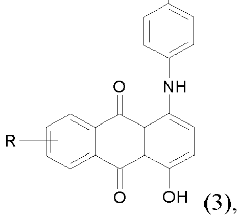
R ausgewählt ist aus der Gruppe, die aus H und p-Methylphenlyamin-Rest besteht;
- R3 Halogen ist;
- n = 4 ist;


- R1 und R2 unabhängig voneinander für einen linearen oder verzweigten Alkylrest oder Halogen stehen;
- n für eine natürliche Zahl zwischen 0 und 4 steht;

- die Reste R(5-20) jeweils unabhängig voneinander Wasserstoff, Methyl, Ethyl, Propyl, Isopropyl, Butyl, Isobutyl, tert.-Butyl, Pentyl, Neopentyl, Hexyl, Thexyl, Fluor, Chlor, Brom, Sulfon oder CN sind und
- M ausgewählt ist aus der Gruppe, die aus Aluminium, Nickel, Cobalt, Eisen, Zink, Kupfer und Mangan besteht,
- I. (1a) and/or (1b) and (4) and (2a) and/or (2b),
- II. (1a) and/or (1b) and (5) and (2a) and/or (2b),
- III. (1a) and/or (1b) and (7),
- IV. (1a) and/or (1b) and (4) and (7),
- V. (1a) and/or (1b) and (5) and (7),
- VI. (4) and (2a) and/or (2b),
- VII.(5) and (2a) and/or (2b),
- VIII. (2a) and/or (2b) and (4) and (6),
- IX. (2a) and/or (2b) and (5) and (6),
- X (3) and (4),
- XI. (3) and (5),
- XII.(3) and (4) and (6),
- XIII. (3) and (5) and (6),
- XIV. (3) and (4) and (7),
- XV. (3) and (5) and (7),
- XVI (3) and (4) and (2a) and/or (2b),
- XVIII. (3) and (5) and (2a) and/or (2b),
- XVIII. (6) and (1a) and/or (1b),
- XIX. (6) and (1a) and/or (1b) and (7),
- XX (1a) and/or (1b) and (8),
- XXI. (7) and (4),
- XXII. (7) and (5),
- XXIII. (1a) and/or (1b),
- XXIV. (2a) and/or (2b),
- XXV. (7),
- XXVI. (2a) and/or (2b) and (7),
- Ra and Rb independently represent a linear or branched alkyl radical or halogen;
- n, independently of the respective R, is a natural number between 0 and 3, the remainder for n=0 being hydrogen;
- Rc and Rd are independently linear or branched alkyl or halogen;
- n, independently of the respective R, is a natural number between 0 and 3, the remainder for n=0 being hydrogen;
R is selected from the group consisting of H and p-methylphenylamine residue;- R3 is halogen;
- n = 4;
- R1 and R2 independently represent a linear or branched alkyl radical or halogen;
- n is a natural number between 0 and 4;
- each R(5-20) is independently hydrogen, methyl, ethyl, propyl, isopropyl, butyl, isobutyl, tert-butyl, pentyl, neopentyl, hexyl, thexyl, fluoro, chloro, bromo, sulfonic or CN; and
- M is selected from the group consisting of aluminum, nickel, cobalt, iron, zinc, copper and manganese
Unter die Bezeichnung "3D-Struktur" fallen Musterungen, Texturen und Narbungen, die eine gezielt in die Oberfläche eingebrachte, räumliche Anordnung und Verteilung einzelner Strukturelemente aufweisen, aus denen für einen Betrachter ein visueller Eindruck eines Optikdesigns entsteht. Dazu sind Strukturelemente enthalten, deren laterale Ausdehnung Dimensionen von bevorzugt mindestens 1 mm, weiter bevorzugt größer als 3 mm, besonders bevorzugt größer als 5 mm aufweisen. Außerdem weisen die Flächennormalen dieser Strukturelemente bevorzugt eine Winkelabweichung von 2 bis 85°, bevorzugt von 3 bis 45°, besonders bevorzugt von 3 bis 30°, bezogen auf die Flächennormalen der angrenzenden Strukturelemente auf. Darüber hinaus liegt die Höhe der 3D Strukturelemente bevorzugt im Bereich von 0,1 mm bis zur halben minimalen Dicke der Schicht a. im Bereich der 3D-Struktur. "Von"/"bis" schließt hierbei die genannte Unter- bzw. Obergrenze ein. Die Höhe der 3D-Struktur bezeichnet hierbei die Differenz zwischen dem höchsten und dem tiefsten Punkt der Struktur, was bezogen auf den Schichtaufbauquerschnitt die Differenz zwischen der minimalen und der maximalen Wanddicke entspricht.The designation "3D structure" includes patterns, textures and grains that have a spatial arrangement and distribution of individual structural elements that are introduced into the surface in a targeted manner, from which a visual impression of an optical design is created for the viewer. For this purpose, structural elements are included whose lateral extent has dimensions of preferably at least 1 mm, more preferably greater than 3 mm, particularly preferably greater than 5 mm. In addition, the surface normals of these structural elements preferably have an angular deviation of 2 to 85°, preferably 3 to 45°, particularly preferably 3 to 30°, based on the surface normals of the adjacent structural elements. In addition, the height of the 3D structural elements is preferably in the range from 0.1 mm to half the minimum thickness of layer a. in the field of 3D structure. "From"/"to" includes the specified lower or upper limit. The height of the 3D structure designates the difference between the highest and the lowest point of the structure, which corresponds to the difference between the minimum and maximum wall thickness in relation to the layer structure cross section.
Ein weiterer Aspekt der Erfindung ist eine Beleuchtungsanlage, beinhaltend mindestens:
- i. einen erfindungsgemäßen Schichtaufbau oder nach dem erfindungsgemäßen Prozess hergestellten Schichtaufbau,
- ii. eine Lichtquelle ii., die so neben der Schicht a. angeordnet ist, dass ein seitliches Einstrahlen von Licht in die Stirnseite der Schicht a. möglich ist;
- iii. gegebenenfalls ein Display, wobei das Display auf der Seite der Schicht b. des Schichtaufbaus angeordnet ist, wobei die Fläche des Displays bevorzugt parallel zu der Flächenausdehnung des Schichtaufbaus ausgerichtet ist, so dass der erfindungsgemäße Schichtaufbau durchleuchtet wird;
- iv. gegebenenfalls eine Lichtquelle iv., wobei die Lichtquelle iv. auf der Seite der Schicht b. des Schichtaufbaus angeordnet ist;
- v. gegebenenfalls einen Sensor, wobei der Sensor auf der Seite der Schicht b. des Schichtaufbaus angeordnet ist, wobei die Fläche des Sensors bevorzugt parallel zu der Flächenausdehnung des Schichtaufbaus ausgerichtet ist;
- vi. gegebenenfalls einen Projektionsapparat, der in der Ebene der Oberfläche A' oder der Oberfläche B' oder der Oberfläche B, oder geometrisch zwischen A' und B eine Abbildungsebene hat, in der das vom Projektionsapparat projizierte Bild/Video scharf ist bzw. entsprechend eingestellt werden kann.
- i. a layer structure according to the invention or a layer structure produced according to the process according to the invention,
- ii. a light source ii. thus placed next to the layer a. is arranged that a lateral irradiation of light into the front side of the layer a. is possible;
- iii. optionally a display, the display on the side of the layer b. of the layer structure is arranged, the surface of the display preferably being aligned parallel to the surface extent of the layer structure, so that the layer structure according to the invention is transilluminated;
- IV. optionally a light source iv., the light source iv. on the side of layer b. of the layer structure is arranged;
- v. optionally a sensor, the sensor on the side of the layer b. of the layer structure is arranged, wherein the surface of the sensor is preferably aligned parallel to the surface extent of the layer structure;
- vi. if necessary, a projection apparatus which has an imaging plane in the plane of surface A' or surface B' or surface B, or geometrically between A' and B, in which the image/video projected by the projection apparatus is sharp or can be adjusted accordingly .
Die Lichtquelle ii. wird bevorzugt als Kantenlicht bezeichnet. Sie besteht bevorzugt aus einem länglich ausgedehnten LED-Modul oder LED-Streifen mit in Reihe angeordneten sog. Einzel-LEDs. Eine Einzel-LED kann z.B. eine Weißlicht-LED oder eine RGB-LED-Gruppe sein.The light source ii. is preferably referred to as edge light. It preferably consists of an elongated LED module or LED strip with so-called individual LEDs arranged in a row. For example, a single LED can be a white light LED or an RGB LED group.
Die Lichtquelle iv. wird bevorzugt als Durchlicht bezeichnet. Sie besteht bevorzugt aus einem LED-Panel mit bevorzugt in einer Matrix angeordneten Einzel-LEDs. Eine Einzel-LED kann eine Weißlicht-LED oder eine RGB-LED-Gruppe sein. Zum Beispiel ist die Lichtquelle iv. ein ISELED LED Modul oder ein Passiv-Matrix-LED-Display. Die Lichtquelle iv. kann alternativ auch ein diffuses Flächenlicht sein, wie z.B. in der
Die Lichtquelle iv. kann alleine oder in Kombination mit einem Display iii. verwendet werden. Kombinationen verschiedener Hinterleuchtungselemente bestehend aus Displays und Lichtquellen sind dabei denkbar.The light source iv. can be used alone or in combination with a display iii. be used. Combinations of different backlighting elements consisting of displays and light sources are conceivable.
Unter Stirnseite der Schicht a. wird die Seite der Dickenausdehnung der Schicht a. verstanden, die sich senkrecht zu der Flächenausdehnung der Schicht a. erstreckt, wie z.B. eine seitliche Kante.Under face of layer a. becomes the side of thickness extension of layer a. understood, which is perpendicular to the surface area of the layer a. extends, such as a lateral edge.
Die Bereiche der seitlichen Kante, die für die Lichteinkopplung in Schicht a verwendet werden ermöglichen bevorzugt eine weitgehend senkrechte Durchstrahlung. Bei weitwinklig abstrahlenden Einzel-LEDs ist die Fläche bevorzugt konkav vor der LED, bei Einzel-LEDs mit Kollimationsoptik ist die Fläche bevorzugt eben.The areas of the lateral edge, which are used for coupling light into layer a, preferably allow largely vertical transmission. In the case of individual LEDs that emit light at a wide angle, the surface is preferably concave in front of the LED; in the case of individual LEDs with collimation optics, the surface is preferably flat.
Der Schichtaufbau weist bevorzugt mindestens eine, bevorzugt mindestens zwei, mehr bevorzugt mindestens drei, besonders bevorzugt alle der folgenden weiteren Merkmale für die Bereiche auf, die vor einem Display-Anzeigefeld liegen:
- Alle Schichten, insbesondere Schichten a., b. und c., sind in Summe nur schwach Licht streuend im sichtbaren Spektralbereich, bevorzugt durch einen Haze-Wert (Opazität, Trübung) nach ASTMD 1003 von kleiner als 20%, bevorzugt kleiner als 15%, weiter bevorzugt kleiner als 10%, um eine gute Lesbarkeit, insbesondere mit hoher Auflösung, gutem Kontrast und guter Farbmetrik einer Punktmatrix-Anzeige zu gewährleisten.
- Die Gesamttransmission Ty des Schichtaufbaus beträgt im sichtbaren Spektrum mindestens 10%, bevorzugt mindestens 15%, weiter bevorzugt mindestens 50%, besonders bevorzugt mindestens 80%, bestimmt nach DIN ISO 13468-2:2006 (D65, 10°).
- All layers, especially layers a., b. and c., are only weakly light-scattering in the visible spectral range, preferably with a haze value (opacity, turbidity) according to ASTMD 1003 of less than 20%, preferably less than 15%, more preferably less than 10%, by a to ensure good readability, in particular with high resolution, good contrast and good colorimetry of a dot matrix display.
- The total transmission Ty of the layer structure in the visible spectrum is at least 10%, preferably at least 15%, more preferably at least 50%, particularly preferably at least 80%, determined according to DIN ISO 13468-2:2006 (D65, 10°).
Der Schichtaufbau weist bevorzugt folgendes weitere Merkmal für seine Bereiche auf, die vor dem Leuchtfeld einer Hinterleuchtung oder eines Anzeigeelements, also auf der Rückseite des Schichtaufbaus, die auf der Seite der Schicht b. als Außenfläche liegen:
- Schicht b. und/oder Schicht c. streuen unabhängig voneinander Licht, um eine homogenere Ausleuchtung eines dahinterliegenden Leuchtelements (Direktlicht) zu erreichen. eine hohe Lichtstreuung ist dann bevorzugt, wenn die Bereiche dieser Schichten keine Anzeigefunktion übernehmen müssen.
- layer b and/or layer c. scatter light independently of each other in order to achieve more homogeneous illumination of a light element behind it (direct light). high light scattering is preferred when the areas of these layers do not have to assume a display function.
Mit dem erfindungsgemäßen Schichtaufbau ist es erstmals möglich, bildgebende Anzeige-Elemente wie Punkt-Matrix-Displays hinter 3D-Reliefstrukturen zu platzieren, weil es über den erfindungsgemäßen Schichtaufbau gelingt, Licht dieser Anzeige zu transmittieren, ohne dass Licht an den geometrischen 3D-Strukturen des Dekors so stark gebrochen, gebeugt oder gestreut wird, dass die Qualität der Anzeige, messbar z.B. durch die Auflösung, Homogenität, Luminanz, Farbpräzision oder Kontrast, maßgeblich verschlechtert wird.With the layer structure according to the invention, it is possible for the first time to place imaging display elements such as dot-matrix displays behind 3D relief structures, because the layer structure according to the invention makes it possible to transmit light from this display without light affecting the geometric 3D structures of the Decor is broken, bent or scattered so much that the quality of the display, measurable e.g. by the resolution, homogeneity, luminance, color precision or contrast, is significantly degraded.
Gleichzeitig kann mit dem erfindungsgemäßen Schichtaufbau durch seitliche Lichteinkopplung in der Schicht a. ein 3D-Dekor beleuchtet und damit für das Auge von vorne sichtbar gemacht werden. Durch Ausschalten der seitlichen Lichtquelle, wie LED-Kantenmodule, wird das 3D-Dekor wieder für das Auge unsichtbar gemacht.At the same time, with the layer structure according to the invention, light can be coupled in from the side in layer a. a 3D decor can be illuminated and thus made visible to the eye from the front. By switching off the side light source, such as LED edge modules, the 3D decor is made invisible to the eye again.
Bevorzugte technische Lösungen für dekorative Licht-optische Effekte in denen der erfindungsgemäße Schichtaufbau als 3D-Dekor eingesetzt wird und die in jeder Kombination möglich sind, sind:
- (D1) Die 3D-Struktur wird als 3D-Dekor für das Auge bei aktiver Beleuchtung mittels Lichtquelle ii. sichtbar, weil sie einen Anteil des auftreffenden Lichts von ihrer Oberfläche nach außen zurückstreut.
- (D2) Die 3D-Struktur wird als 3D-Dekor für das Auge bei aktiver Beleuchtung mittels Lichtquelle ii. sichtbar, weil sie in Teilbereichen oder als ganze Fläche Licht nach außen zurückspiegelt oder -streut.
- (D3) Die vordere Schicht a. dient als flächiger Lichtleiter für Licht, insbesondere Licht von Leuchtdioden (LED), das über eine oder mehrere Kanten oder mittels einer Einkoppeloptik über eine Oberfläche in den Lichtleiter eingekoppelt wird und in diesem durch totale interne Reflexion propagiert. Die 3D-Strukturen unterbrechen die lineare Ausbreitung des Lichts durch in den Lichtleiter hineinragende oder erweiternde schräge Flächen, die den Winkel der Lichtausbreitung lokal verändert und damit die totale interne Reflexion unterbrechen kann. Lichtanteile, die nicht mehr der totalen interne Reflexion unterliegen, treten nach außen und werden als dynamisches Dekorlicht wahrgenommen. Die Propagationsverluste durch die 3D-Struktur sind dennoch so gering, dass die Flächenlichtleitung gewährleistet ist und das 3D-Dekor die Funktion eines flächigen Dekorlichts übernimmt. Bei aktiver Beleuchtung nur aus einer Richtung (z.B. über eine Kante) ist der Kontrast der 3D-Struktur besonders hoch wegen der Schattenbildung, die durch flache Beleuchtung in Verbindung mit tiefen und dem Licht abgewandten Strukturen entsteht.
- (D4) Dies 3D- Struktur liegt zu 10
bis 100 %, bevorzugt zu 20 bis 90 %, mehr bevorzugt zu 30 bis 80 % über einem Anzeige-Element, bezogen auf die Außenfläche des Anzeige-Elements. - (D5) Die 3D- Struktur liegt mindestens partiell, bevorzugt zu 20 bis 90 %, mehr bevorzugt zu 30 bis 80 % über einem Anzeige-Element, bezogen auf die Außenfläche des Anzeige-Elements und erstreckt sich über dieses hinaus.
- (D6) Fade-out: Die 3D- Struktur hat einen Fade-out Effekt, bevorzugt im Bereich des Anzeige-Elements, der z.B. durch Abnahme in der Dekortiefe oder seiner Flächenanteile realisiert werden kann. Mit Fade-out Effekt ist gemeint, dass die 3D- Struktur im Anzeigebereich des Anzeige-Elements optisch fließend und nicht scharf in eine plane Fläche übergeht, wobei die Elemente der 3D-Struktur in ihrer Anzahl und/oder relativen Flächenbelegung und/oder Strukturtiefe kontinuierlich abnehmen, beginnend im Bereich außerhalb des Anzeige-Elements und endend im Anzeigebereich des Anzeige-Elements.
- (D7) Black Panel: Die 3D- Struktur wird für das Auge bei ausgeschalteter Lichtquelle ii. und ausgeschaltetem Display nicht mehr erkennbar, wobei das Kontrastverhältnis im Bereich der 3D- Struktur bei guten ambienten Lichtbedingungen (60
bis 120 cd/m2 Leuchtdichte, homogene Ausleuchtung, ohne Blendung) kleinerals 2,5 : 1 ist. Man erhält einen Black-Panel-Effekt, falls für Schicht c. eine stark absorbierende Black Panel Folie gewählt wird, die durch eine Lichttransmission von 10 bis 50%, bevorzugt von 15 bis 35%, mehr bevorzugt von 20 bis 25% gekennzeichnet ist. - (D8) White Panel oder Grey Panel: Ein White Panel Effekt bzw. Grey Panel Effekt, wenn für Schicht c. eine Streufolie gewählt wird mit einer Lichttransmission von 70 bis 92%, bevorzugt von 73 bis 85% und einem Halbwertswinkel für das gestreute Licht von 15 bis 50°, bevorzugt von 25 bis 50°.
- (D9) Lichtmischung: Überlappen Dekorlicht und Licht des Displays bzw. Lichtquelle iv., so findet eine Lichtmischung statt, mit additiver Farbmischung und mit Intensitätsanstieg im Überlappbereich..
- (D1) The 3D structure is used as a 3D decoration for the eye with active illumination by means of light source ii. visible because it scatters part of the incident light back from its surface to the outside.
- (D2) The 3D structure is used as a 3D decoration for the eye with active illumination by means of a light source ii. Visible because it reflects or scatters light back to the outside in parts or as a whole surface.
- (D3) The front layer a. serves as a flat light guide for light, in particular light from light-emitting diodes (LEDs), which is coupled into the light guide via one or more edges or by means of a coupling optics via a surface and propagates there by total internal reflection. The 3D structures interrupt the linear propagation of the light by protruding or widening inclined surfaces into the light guide, which locally changes the angle of the light propagation and can thus interrupt the total internal reflection. Parts of the light that are no longer subject to total internal reflection emerge outwards and are perceived as dynamic decorative light. The propagation losses due to the 3D structure are still so low that the surface light guidance is guaranteed and the 3D decor takes over the function of a surface decor light. With active illumination from only one direction (eg over an edge), the contrast of the 3D structure is particularly high because of the shadow formation that occurs through flat illumination in connection with deep structures that are turned away from the light.
- (D4) This 3D structure is 10 to 100%, preferably 20 to 90%, more preferably 30 to 80% over a display element, based on the outer surface of the display element.
- (D5) The 3D structure at least partially, preferably 20 to 90%, more preferably 30 to 80% overlies and extends beyond a display element, based on the outer surface of the display element.
- (D6) Fade-out: The 3D structure has a fade-out effect, preferably in the area of the display element, which can be realized, for example, by reducing the depth of the decor or its surface proportions. The fade-out effect means that the 3D structure in the display area of the display element transitions visually smoothly and not sharply into a flat surface, with the elements of the 3D structure being continuous in terms of their number and/or relative area occupancy and/or structure depth decrease, starting in the area outside the display element and ending in the display area of the display element.
- (D7) Black Panel: The 3D structure is visible to the eye when the light source is switched off ii. no longer recognizable when the display is switched off, with the contrast ratio in the area of the 3D structure being less than 2.5 : 1 under good ambient lighting conditions (60 to 120 cd/m 2 luminance, homogeneous illumination, without glare). A black panel effect is obtained if for layer c. a strongly absorbing black panel film is selected, which is characterized by a light transmission of 10 to 50%, preferably 15 to 35%, more preferably 20 to 25%.
- (D8) White Panel or Gray Panel: A white panel effect or gray panel effect, respectively, if for layer c. a scattering film is selected with a light transmission of 70 to 92%, preferably 73 to 85% and a half-power angle for the scattered light of 15 to 50°, preferably 25 to 50°.
- (D9) Light mixing: If the decorative light and the light of the display or light source iv. overlap, light mixing takes place, with additive color mixing and with an increase in intensity in the overlapping area.
Das Kontrastverhältnis ist definiert durch Lmax / Lmin, mit Lmax = maximale Leuchtdichte in der 3D-Struktur und Lmin = minimale Leuchtdichte in den dunkelsten Bereichen der 3D-Struktur.The contrast ratio is defined by Lmax / Lmin, with Lmax = maximum luminance in the 3D structure and Lmin = minimum luminance in the darkest areas of the 3D structure.
Der erfindungsgemäße Schichtaufbau ermöglicht in Kombination mit Leucht- und Anzeigeelementen insgesamt mindestens vier individuelle Betriebszustände:
- 1. Kantenbeleuchtung an, so dass die 3D- Struktur sichtbar wird und Display an, so dass auch die Anzeige sichtbar wird, auch im Dekorbereich;
- 2. Kantenbeleuchtung aus, so dass die 3D- Struktur unsichtbar bleibt und Display aus, so dass die Anzeige nicht sichtbar ist, auch nicht im Dekorbereich;
- 3. Kantenbeleuchtung an, so dass die 3D- Struktur sichtbar wird und Display aus, so dass die Anzeige nicht sichtbar ist, auch nicht im Dekorbereich;
- 4. Kantenbeleuchtung aus, so dass die 3D- Struktur unsichtbar bleibt und Display an, so dass die Anzeige sichtbar ist, auch im Dekorbereich.
- 1. Edge lighting on so that the 3D structure is visible and display on so that the display is also visible, including in the decor area;
- 2. Edge lighting off so that the 3D structure remains invisible and display off so that the display is not visible, even in the decorative area;
- 3. Edge lighting on so that the 3D structure is visible and display off so that the display is not visible, even in the decorative area;
- 4. Edge lighting off so that the 3D structure remains invisible and display on so that the display is visible, even in the decorative area.
Der erfindungsgemäße Schichtaufbau wird bevorzugt mit Elementen ausgewählt aus der Gruppe bestehend aus einer oder mehreren Display-Anzeigen, mit einer oder mehreren Kantenbeleuchtungen und mit einem oder mehreren Durchlicht-Einheiten oder einer Kombination aus mindestens zwei hiervon.The layer structure according to the invention is preferably selected with elements from the group consisting of one or more displays, with one or more edge lighting and with one or more transmitted light units or a combination of at least two of these.
Der erfindungsgemäße Schichtaufbau wird bevorzugt als Display-Abdeckung verwendet.The layer structure according to the invention is preferably used as a display cover.
Der erfindungsgemäße Schichtaufbau wird bevorzugt als Sensorabdeckung verwendet. Bevorzugte Sensoren sind ausgewählt aus der Gruppe bestehend aus Innenraumkameras, Innenraum-LiDARe, RADARe, Infrarot-Kameras, High Dynamic Range Kameras oder einer Kombination aus mindestens zwei hiervon.The layer structure according to the invention is preferably used as a sensor cover. Preferred sensors are selected from the group consisting of interior cameras, interior LiDARe, RADARe, infrared cameras, high dynamic range cameras or a combination of at least two of these.
Der erfindungsgemäße Schichtaufbau wird bevorzugt als Antennenabdeckung verwendet. Antennen sind beispielsweise 5G-Antennen.The layer structure according to the invention is preferably used as an antenna cover. Antennas are 5G antennas, for example.
Bevorzugt weist der erfindungsgemäße Schichtaufbau mindestens eine, bevorzugt zwei, mehr bevorzugt drei, noch mehr bevorzugt vier, besonders bevorzugt alle der folgenden Schichten oder Beschichtungen auf, ausgewählt aus:
- Der Schichtaufbau weist zusätzlich eine vorderseitige Schutzschicht auf, z.B. einen kratzbeständigen Lack oder einen Schutzlack gegen chemisch aggressive Medien;
- Der Schichtaufbau weist zusätzlich eine rückseitige Schicht auf, z.B. ausgeführt als transparente Elektrode oder als transparente leitfähig beschichtete Folie, um dem Verbund eine Touch Funktion hinzuzufügen;
- Der Schichtaufbau weist auf der Sichtseite eine zusätzliche Anti-Reflex und/oder Anti-Fingerprint Schicht auf;
- Der Schichtaufbau weist auf der Sichtseite eine zusätzliche Niedrig-Reflex-Schicht auf;
- Der Schichtaufbau weist auf der Sichtseite eine zusätzliche Anti-Fingerprint-Schicht auf.
- The layer structure also has a protective layer on the front, for example a scratch-resistant lacquer or a protective lacquer against chemically aggressive media;
- The layer structure also has a rear layer, for example designed as a transparent electrode or as a transparent conductively coated film, in order to add a touch function to the composite;
- The layer structure has an additional anti-reflection and/or anti-fingerprint layer on the visible side;
- The layer structure has an additional low-reflection layer on the visible side;
- The layer structure has an additional anti-fingerprint layer on the visible side.
In einer bevorzugten Ausführungsform der Beleuchtungsanlage bildet die Beleuchtungsanlage einen Teil der Karosserie eines Fahrzeugs, welcher zur Kommunikation mit Personen dient. Bevorzugt ist der Teil der Karosserie ausgewählt aus der Gruppe bestehend aus einem Kühlergrill, einer Stoßstange, einem Frontgrill, Dachmodul, Sensorbox, Stoßfänger, Funktionsleuchte, Heckleuchte, Scheinwerfer und allen anderen Leuchten für Fahrzeug-Außenanwendungen, oder einer Kombination aus mindestens zwei davon.In a preferred embodiment of the lighting system, the lighting system forms part of the body of a vehicle, which is used for communication with people. The part of the body is preferably selected from the group consisting of a radiator grille, a bumper, a front grille, roof module, sensor box, bumper, functional light, rear light, headlight and all other lights for vehicle exterior applications, or a combination of at least two of them.
In einer bevorzugten Ausführungsform der Beleuchtungsanlage deckt die Beleuchtungsanlage einen Teil der Fahrzeug-Innenraum-Oberfläche ab, um ein HMI oder eine ambiente Beleuchtung abzubilden.In a preferred embodiment of the lighting system, the lighting system covers part of the vehicle interior surface in order to display an HMI or ambient lighting.
In einer bevorzugten Ausführungsform der Beleuchtungsanlage handelt es sich bei der Lichtquelle ii. um eine LED-Kantenbeleuchtung.In a preferred embodiment of the lighting installation, the light source ii. around an LED edge lighting.
In einer bevorzugten Ausführungsform der Beleuchtungsanlage ist der Sensor v. ausgewählt aus der Gruppe bestehend aus Innenraumkameras, Innenraum-LiDARe, RADARe, Infrarot-Kameras, High Dynamic Range Kameras oder einer Kombination aus mindestens zwei hiervon.In a preferred embodiment of the lighting system, the sensor is v. selected from the group consisting of interior cameras, interior LiDARe, RADARe, infrared cameras, high dynamic range cameras or a combination of at least two of these.
Die Erfindung wird in den Figuren
- Figur 1:
- Schematischer Aufbau für eine Display-Abdeckung nach dem Stand der Technik
- Figur 2:
- Beispiel für einen erfindungsgemäßen Schichtaufbau
- Figur 3:
- Beispiel für einen erfindungsgemäßen Schichtaufbau
- Figur 4:
- Beispiel für einen erfindungsgemäßen Beleuchtungsanlage mit einem erfindungsgemäßen Schichtaufbau
- Figur 5:
- Beispiel für unterschiedliche Zustände der erfindungsgemäßen Beleuchtungsanlage aus
Figur 4
- Figure 1:
- Schematic layout for a prior art display cover
- Figure 2:
- Example of a layer structure according to the invention
- Figure 3:
- Example of a layer structure according to the invention
- Figure 4:
- Example of a lighting system according to the invention with a layer structure according to the invention
- Figure 5:
- Example of different states of the lighting system according to the invention
figure 4
Die Erfindung wird anhand der nachfolgenden Beispiele näher erläutert, ohne jedoch darauf beschränkt zu sein.The invention is explained in more detail using the following examples, but without being restricted thereto.
Für die Schicht a. und die Schicht b. wurde verwendet: Transparentes Makrolon® Ai der Covestro Deutschland AG: aromatisches Polycarbonat auf Basis von Bisphenol A mit einer MVR von 19 cm3/(10 min), bestimmt bei 300 °C und 1,2 kg gemäß DIN ISO 1133:2012-03, enthaltend UV-Absorber und Entformer. Ty, gemessen bei einer Dicke von 2 mm gemäß ISO 13468-2:2006 (D65, 10°): 88,07 %. Trübung, bestimmt nach ASTM D1003:2013 bei einer Schichtdicke von 2 mm: 0,68 %. Das Polycarbonat lag als Granulat für den Spritzguss vor. Zur Vorbehandlung wurde das Polycarbonat für 4 Stunden bei 120 °C in Trockenluft getrocknet. Das Polycarbonat hat einen Brechungsindex von 1,585 nach ISO 489 (Verfahren A).For layer a. and layer b. was used: Transparent Makrolon® Ai from Covestro Deutschland AG: aromatic polycarbonate based on bisphenol A with an MVR of 19 cm 3 /(10 min), determined at 300° C. and 1.2 kg in accordance with DIN ISO 1133:2012-03 , containing UV absorbers and mold release agents. Ty, measured at a thickness of 2 mm according to ISO 13468-2:2006 (D65, 10°): 88.07%. Haze, determined according to ASTM D1003:2013 at a layer thickness of 2 mm: 0.68%. The polycarbonate was in the form of granules for injection molding. For pretreatment, the polycarbonate was dried in dry air at 120° C. for 4 hours. The polycarbonate has a refractive index of 1.585 according to ISO 489 (Method A).
Für die Zwischenschicht c. wurde verwendet: Makrofol® LM 296 1-2 760125 der Covestro Deutschland AG: grau eingefärbte Extrusionsfolie auf Basis des Polycarbonats Makrolon®. Die Extrusionsfolie hat einen Brechungsindex von 1,596 nach ISO 489 (Verfahren A). Die Folien wurden jeweils auf die Maße 200 mm x 150 mm bei einer Dicke von 0,5 mm zugeschnitten. Sie besaßen eine glänzende Oberfläche auf der 1er Seite und eine sehr fein mattierte Oberfläche auf ihrer 2er Seite.For the intermediate layer c. was used: Makrofol ® LM 296 1-2 760125 from Covestro Deutschland AG: gray colored extruded film based on the polycarbonate Makrolon ® . The extruded film has a refractive index of 1.596 according to ISO 489 (Method A). The foils were each cut to the
Zur Herstellung der 3D-Struktur wurde ein metallischer Platten-Werkzeugeinsatz bereitgestellt mit einer 3D-Struktur, wie in Abbildung B1.1 zu sehen. Abbildung B1.2 weist typische Strukturgrößen der Einzelelemente von 7 bis 16 mm und eine Höhe der 3D-Strukturelemente von 0,49 mm auf. Daraus resultieren Winkel zwischen der Strukturflächennormale und der planen und glatten zweiten Wand der Spritzgussform von 3,35°. Damit ist diese Struktur geeignet, um erfindungsgemäße Schichtstrukturen herzustellen und einen experimentellen Nachweis der gewünschten Effekte bei erfindungsgemäßen Schichtstrukturen zu ermöglichen.To produce the 3D structure, a metallic plate tool insert was provided with a 3D structure as shown in Figure B1.1. Figure B1.2 shows typical structure sizes of the individual elements of 7 to 16 mm and a height of the 3D structure elements of 0.49 mm. This results in an angle of 3.35° between the structural surface normal and the flat and smooth second wall of the injection mold. This structure is therefore suitable for producing layer structures according to the invention and for enabling experimental verification of the desired effects in layer structures according to the invention.
Abbildung B1.1: 3D-Modell einer Struktur mit pyramidalen Elementen unterschiedlicher Verteilung auf einer Platte mit dem Flächenmaßen 200 mm x 150 mm.

Abbildung B1.2: Maße der pyramidalen Elemente [mm]. Oben: Seitenansicht. Unten: Draufsicht.
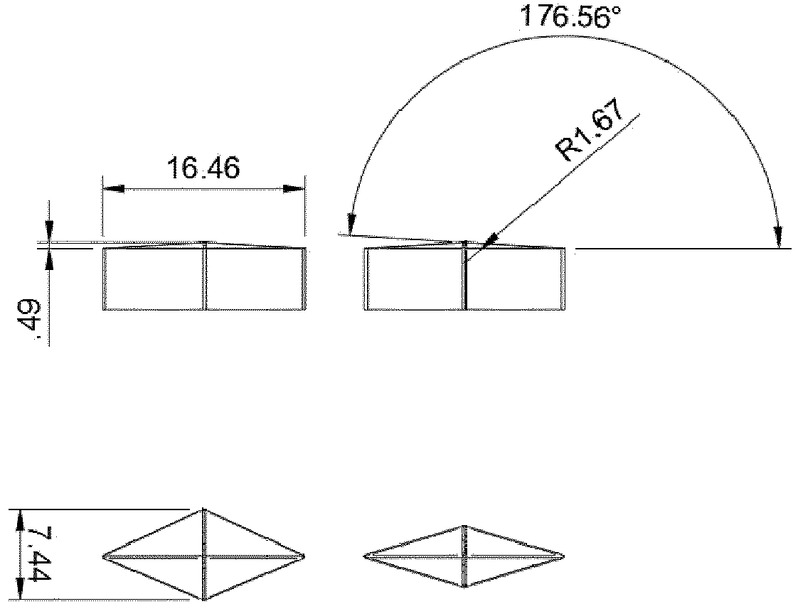
Für die Versuche wurden Spritzguss-Musterplatten mit rückseitiger 3D-Struktur und den Maßen 200 mm x 150 mm x 3 mm aus Polycarbonat-Zusammensetzungen hergestellt.For the tests, injection-molded sample plates with a 3D structure on the back and dimensions of 200 mm×150 mm×3 mm were produced from polycarbonate compositions.
Die Lichttransmission der Makrofol® Folie betrug vor der Verarbeitung 25% nach DIN ISO 13468-2:2006 (D65, 10°). Damit ist sie als Black Panel Folie zu verwenden.Before processing, the light transmission of the Makrofol ® film was 25% according to DIN ISO 13468-2:2006 (D65, 10°). This means it can be used as a black panel film.
Auf einer HM270 Spritzgießmaschine der Wittmann Battenfeld GmbH wurde ein mehrschichtiges Formteil mit den Maßen 200 mm x 150 mm x 6 mm hergestellt.A multi-layer molded part measuring 200 mm×150 mm×6 mm was produced on an HM270 injection molding machine from Wittmann Battenfeld GmbH.
Dazu wurde in einem ersten Schritt jeweils eine Makrofol® Folie als Schicht c., aus dem zuvor erwähnten Material, in diejenige Werkzeughälfte eines Stahlwerkzeugs mit den Forminnenmaßen 200 mm x 150 mm x 3 mm eingelegt, deren Oberfläche mit der oben beschriebenen und in Abbildung B1.1 gezeigten 3D-Struktur versehen war. Die andere Werkzeughälfte besaß eine hochglänzende Oberfläche. Nach dem Schließen des Werkzeugs wurde das bei 305 °C aufgeschmolzene transparente Polycarbonat-Material mit einem maximalen spezifischen Einspritzdruck von ca. 2000 bar in das Werkzeug eingespritzt, um die Schicht a. zu bilden. Die Folie der Schicht c. wurde bei diesem Überspritzen jeweils in die Struktur der Werkzeugoberfläche gedrückt. Welche Oberflächenseite, also die glatte 1er-Seite oder die raue 2er-Seite zur Struktur eingelegt wurde, war dabei unerheblich. Die Temperatur der Werkzeugwand lag auf beiden Seiten, also sowohl auf der Auswerferseite sowie auch auf der gegenüberliegenden Einspritzseite bei 90 °C. Die Einspritzzeit betrug etwa 2,5 Sekunden. Nach einer Nachdruckzeit von 15 Sekunden (spezifischer Nachdruck: 850 bar) und einer Kühlzeit von 20 Sekunden wurde das Werkzeug geöffnet und das Formteil entnommen. Die Makrolon-Schicht bildet die Schicht a.; die Makrofol-Folie die Schicht c, im Folgenden als Polycarbonatplatte bezeichnet.For this purpose, in a first step, a Makrofol ® film was placed as layer c., made of the material mentioned above, into that mold half of a steel mold with the mold
Anschließend wurde das Spritzgießwerkzeug auf die Forminnenmaße 200 mm x 150 mm x 6 mm umgebaut und die strukturierte Stahloberfläche entfernt, sodass jetzt beide Werkzeughälften eine hochglänzende Oberfläche besaßen. Die Polycarbonatplatte wurde mit der 3D strukturierten Seite bei 90 °C für 15 Minuten in einem Wärmeschrank vortemperiert. Daraufhin wurde diese Platte wieder in die erste Werkzeughälfte des Stahlwerkzeugs mit den Forminnenmaßen 200 x 150 x 6 mm eingelegt, die strukturierte Oberfläche mit der jeweiligen Folie zur zweiten Werkzeughälfte zeigend. Nach dem Schließen des Werkzeugs wurde das bei 305 °C aufgeschmolzene transparente Polycarbonat-Material mit einem maximalen spezifischen Einspritzdruck von ca. 2000 bar in das Werkzeug auf die Polycarbonatplatte, auf die Seite mit der 3D strukturierten Folie eingespritzt. Die Temperatur der Werkzeugwand lag auf der Auswerferseite bei 100 °C, auf der gegenüberliegenden Einspritzseite bei 80 °C. Die Einspritzzeit betrug erneut 2,5 Sekunden. Nach einer Nachdruckzeit von 15 Sekunden (spezifischer Nachdruck: 800 bar) und einer Kühlzeit von 30 Sekunden wurde das Werkzeug geöffnet und das fertige Formteil mit einer Gesamtdicke von etwa 6 mm und zwei hochglänzenden Seiten entnommen. Der erhaltene Schichtaufbau hat nun eine weitere Schicht b., und weist den erfindungsgemäßen dreilagigen Schichtenaufbau auf mit innenliegender 3D Struktur in Form der strukturierten "Black-Panel-Folie".The injection mold was then converted to the internal dimensions of 200 mm x 150 mm x 6 mm and the structured steel surface was removed so that both mold halves now had a high-gloss surface. The polycarbonate plate was preheated with the 3D structured side at 90° C. in a heating cabinet for 15 minutes. This plate was then placed back into the first mold half of the steel mold with the internal mold dimensions 200 x 150 x 6 mm, showing the structured surface with the respective foil to the second mold half. After the mold was closed, the transparent polycarbonate material, melted at 305 °C, was injected into the mold onto the polycarbonate sheet, on the side with the 3D structured film, with a maximum specific injection pressure of approx. 2000 bar. The temperature of the mold wall was 100 °C on the ejector side and 80 °C on the opposite injection side. The injection time was again 2.5 seconds. After a holding pressure time of 15 seconds (specific holding pressure: 800 bar) and a cooling time of 30 seconds, the tool was opened and the finished molded part with a total thickness of about 6 mm and two high-gloss sides was removed. The layer structure obtained now has a further layer b., and has the three-layer structure according to the invention with an internal 3D structure in the form of the structured “black panel film”.
Die Lichttransmission des erhaltenen Schichtaufbaus lag bei 21%nach DIN ISO 13468-2:2006 (D65, 10°).The light transmission of the layer structure obtained was 21% according to DIN ISO 13468-2:2006 (D65, 10°).
Bei normalem Raumlicht (Deckenlicht) und Blick auf die Schicht a. erscheint die Schicht sowie der gesamte Schichtaufbau gleichmäßig in dunklem anthrazit, ohne dass ein Dekor zu erkennen ist. Für die Sichtbarmachung des Dekors wurde der Formkörper in eine Lichtbox eingespannt, welche für die Aufnahme von Platten mit den Maßen 200 mm x 150 mm gefertigt wurde. Diese Lichtbox besaß einen rund um die Platte auf Höhe der Kanten laufenden LED-Streifen für die Kantenbeleuchtung sowie etwas Platz auf der Rückseite, um ein Display-Modul, z.B. Smart Phone oder eine LED Matrixleuchte unterzubringen, wie dies schematisch in
Die optischen Effekte werden durch die Bilder aus
Schicht a. und b. enthielten Makrolon® wie in Beispiel 1, jedoch wurde für die Zwischenschicht c. Makrofol® LM 296 1-2 der Covestro Deutschland AG verwendet: grau eingefärbte Extrusionsfolie auf Basis des Polycarbonats Makrolon® und einer Lichttransmission gemäß DIN ISO 13468-2:2006 (D65, 10°) von 50%. Die Extrusionsfolie hat einen Brechungsindex von 1,59 nach ISO 489 (Verfahren A).layer a. and b. contained Makrolon ® as in Example 1, but for the intermediate layer c. Makrofol® LM 296 1-2 from Covestro Deutschland AG used: gray colored extrusion film based on the polycarbonate Makrolon® and a light transmission according to DIN ISO 13468-2:2006 (D65, 10°) of 50%. The extruded film has a refractive index of 1.59 according to ISO 489 (method A).
Alle optischen Effekte, wie oben zu Beispiel 1 beschreiben, ließen sich auch mit diesem erfindungsgemäßen Schichtaufbau darstellen. Im Vergleich zu Beispiel 1 ist das Display-Bild heller, aber die 3D-Struktur subjektiv etwas kontrastärmer sichtbar. Daraus lässt sich schlussfolgern: Je größer die Absorption der Schicht c. ist (also desto mehr Farbstoffe in der Folie sind), desto besser zeichnet sich die 3D-Struktur bei der Kantenbeleuchtung ab.All optical effects, as described above for example 1, could also be produced with this layer structure according to the invention. Compared to example 1, the display image is brighter, but the 3D structure is subjectively visible with somewhat less contrast. From this it can be concluded: the greater the absorption of layer c. (i.e. the more dyes are in the foil), the better the 3D structure stands out with edge lighting.
Schicht a. und b. enthielten Makrolon® wie in Beispiel 2, jedoch wurde für die Zwischenschicht c. verwendet: Makrofol® LM 296 1-2 der Covestro Deutschland AG: grau eingefärbte Extrusionsfolie auf Basis des Polycarbonats Makrolon® und einer Transmission gemäß DIN ISO 13468-2:2006 (D65, 10°) von 75%. Die Extrusionsfolie hat einen Brechungsindex von 1,59 nach ISO 489 (Verfahren A).layer a. and b. contained Makrolon ® as in Example 2, but for the intermediate layer c. used: Makrofol® LM 296 1-2 from Covestro Deutschland AG: gray-colored extrusion film based on the polycarbonate Makrolon® and a transmission according to DIN ISO 13468-2:2006 (D65, 10°) of 75%. The extruded film has a refractive index of 1.59 according to ISO 489 (method A).
Die optischen Effekte ließen sich mit diesem Schichtaufbau zu einem wesentlichen Teil erreichen. Im Vergleich zu Beispiel 2 ist das Display-Bild nochmals heller, das 3D-Dekor subjektiv nochmals kontrastärmer und die 3D-Struktur zeichnet sich im Ambientelicht (z.B. Büroraum mit indirektem Deckenlicht) leicht ab. Dennoch konnte das Display klar durch die 3D-Struktur gelesen werden egal, ob das Kantenlicht eingeschaltet war oder nicht. Die 3D-Struktur war bei eingeschalteten Kantenlicht gut sichtbar.The optical effects could be achieved to a large extent with this layer structure. In comparison to example 2, the display image is even brighter, the 3D decor is subjectively even lower in contrast and the 3D structure is easily discernible in the ambient light (e.g. office room with indirect ceiling light). Still, the display could be read clearly through the 3D structure no matter whether the edge light was on or not. The 3D structure was clearly visible with the edge light on.
Schicht a. und b. enthielten Makrolon® wie in Beispiel 1, jedoch wurde für die Zwischenschicht c. verwendet: Makrofol®LM 309 der Covestro Deutschland AG: 300 µm dicke Diffusorfolie auf Basis des Polycarbonats Makrolon®, einer Transmission gemäß DIN ISO 13468-2:2006 (D65, 10°) von 86% und einem Halbwertswinkel von 20° gemäß DIN 5036:1978 bezogen auf die Lichtintensität.layer a. and b. contained Makrolon ® as in Example 1, but for the intermediate layer c. used: Makrofol ® LM 309 from Covestro Deutschland AG: 300 µm thick diffuser film based on the polycarbonate Makrolon ® , a transmission according to DIN ISO 13468-2:2006 (D65, 10°) of 86% and a half-power angle of 20° according to DIN 5036 :1978 related to light intensity.
Die visuelle Bewertung erfolgte wie in den vorangegangenen Beispielen. Alle optischen Effekte ließen sich auch mit diesem Schichtaufbau darstellen. Anstelle des Black Panel Effekts trat hier ein sogenannter White Panel Effekt auf: Die Diffusorfolie als Schicht c. streute ambientes Licht zurück zum Beobachter. Dieses strukturlose Licht in Verbindung mit breiten Streuwinkeln löste die 3D-Struktur optisch auf und erzeugte beim Beobachter den Eindruck einer gleichmäßig weißlich hellen Fläche. Weil die Ebene des Display-Panels nur ca. 4 mm hinter der Diffusorebene lag, erschien das Display-Bild noch immer scharf. Der Diffusor-Effekt verbesserte sogar die Bildhelligkeit bei Beobachtung von schräger Position. Durch die White Panel Folie lässt sich also das 3D-Dekor bei ausgeschalteter Kantenbeleuchtung in ambienter Lichtumgebung unsichtbar gestalten und durch Kantenbeleuchtung sichtbar machen. Gleiches gilt für Hinterleuchtung (Display): Ausgeschaltet sind sie unsichtbar und eingeschaltet sichtbar.The visual evaluation was carried out as in the previous examples. All optical effects could also be displayed with this layer structure. Instead of the black panel effect, a so-called white panel effect appeared here: the diffuser film as layer c. scattered ambient light back to the observer. This structureless light in conjunction with wide scattering angles optically resolved the 3D structure and gave the observer the impression of a uniformly whitish bright surface. Because the level of the display panel was only about 4 mm behind the level of the diffuser, the display image still appeared sharp. The diffuser effect even improved image brightness when observing from an oblique position. With the white panel film, the 3D decor can be designed to be invisible in an ambient light environment when the edge lighting is switched off and made visible by edge lighting. The same applies to backlighting (display): they are invisible when switched off and visible when switched on.
Claims (15)
(E5) die Schicht c. ist als Licht streuende Schicht ausgebildet, insbesondere durch eine Lichttransmission von 70 bis 92%, bevorzugt von 73 bis 85% und einen Halbwertswinkel für das gestreute Licht von 15 bis 50°, bevorzugt von 25 bis 50°.The layer structure according to any one of the preceding claims, wherein the layer structure has the following feature:
(E5) the layer c. is designed as a light-scattering layer, in particular with a light transmission of 70 to 92%, preferably 73 to 85% and a half-value angle for the scattered light of 15 to 50°, preferably 25 to 50°.
Applications Claiming Priority (1)
| Application Number | Priority Date | Filing Date | Title |
|---|---|---|---|
| EP21217625 | 2021-12-23 |
Publications (1)
| Publication Number | Publication Date |
|---|---|
| EP4201664A1 true EP4201664A1 (en) | 2023-06-28 |
Family
ID=79021899
Family Applications (1)
| Application Number | Title | Priority Date | Filing Date |
|---|---|---|---|
| EP22214036.0A Pending EP4201664A1 (en) | 2021-12-23 | 2022-12-16 | Light and display cover with three-dimensional decoration |
Country Status (1)
| Country | Link |
|---|---|
| EP (1) | EP4201664A1 (en) |
Cited By (1)
| Publication number | Priority date | Publication date | Assignee | Title |
|---|---|---|---|---|
| DE102022130159A1 (en) * | 2022-11-15 | 2024-05-16 | Morino Stübe | DISPLAY PROTECTION DEVICE AND METHOD FOR THE PRODUCTION THEREOF |
Citations (22)
| Publication number | Priority date | Publication date | Assignee | Title |
|---|---|---|---|---|
| US2991273A (en) | 1956-07-07 | 1961-07-04 | Bayer Ag | Process for manufacture of vacuum moulded parts of high molecular weight thermoplastic polycarbonates |
| US2999835A (en) | 1959-01-02 | 1961-09-12 | Gen Electric | Resinous mixture comprising organo-polysiloxane and polymer of a carbonate of a dihydric phenol, and products containing same |
| US2999846A (en) | 1956-11-30 | 1961-09-12 | Schnell Hermann | High molecular weight thermoplastic aromatic sulfoxy polycarbonates |
| US3148172A (en) | 1956-07-19 | 1964-09-08 | Gen Electric | Polycarbonates of dihydroxyaryl ethers |
| US3271367A (en) | 1955-03-26 | 1966-09-06 | Bayer Ag | Thermoplastic polycarbonates of dihydroxydiarylene sulfones and their preparation |
| FR1561518A (en) | 1967-03-10 | 1969-03-28 | ||
| DE1570703A1 (en) | 1964-10-07 | 1970-02-12 | Gen Electric | Hydrolytically stable polycarbonates and processes for their production |
| DE2036052A1 (en) | 1970-07-21 | 1972-01-27 | Milchwirtschafthche Forschungs und Untersuchungs Gesellschaft mbH, 2100 Hamburg | Working up of additives in fat and protein - contng foodstuffs |
| DE2063050A1 (en) | 1970-12-22 | 1972-07-13 | Bayer | Saponification-resistant polycarbonates |
| DE2211956A1 (en) | 1972-03-11 | 1973-10-25 | Bayer Ag | PROCESS FOR THE PREPARATION OF SEAP-STABLE BLOCK COPOLYCARBONATES |
| DE3832396A1 (en) | 1988-08-12 | 1990-02-15 | Bayer Ag | Dihydroxydiphenylcycloalkanes, their preparation, and their use for the preparation of high-molecular-weight polycarbonates |
| US4982014A (en) | 1988-08-12 | 1991-01-01 | Bayer Aktiengesellschaft | Dihydroxydiphenyl cycloalkanes, their production and their use for the production of high molecular weight polycarbonates |
| DE10057165A1 (en) | 2000-11-16 | 2002-05-23 | Basf Ag | A granulate pigment preparation e.g. for automobile body parts comprises at least two different pigments, thermoplastic polymer(s) and optionally a dispersing agent |
| US20020089468A1 (en) | 1997-02-13 | 2002-07-11 | Hans Kurt Wedel | Instrument panel with system of transparent colored layers |
| DE10211270A1 (en) | 2002-03-13 | 2003-10-02 | Siemens Ag | display |
| US20040066645A1 (en) | 2002-10-03 | 2004-04-08 | John Graf | Bulk diffuser for flat panel display |
| WO2007135032A2 (en) | 2006-05-23 | 2007-11-29 | Basf Se | Use of hyperbranched polycarbonates as a dispersing agent for pigments |
| US20090268296A1 (en) | 2008-04-29 | 2009-10-29 | Motorola, Inc. | Transparent display cover and method of making |
| EP2652029A2 (en) | 2010-12-17 | 2013-10-23 | Bayer Intellectual Property GmbH | Organic colorants and colored polymer compositions having high stability against weathering |
| EP2982501A1 (en) * | 2013-04-05 | 2016-02-10 | Mitsubishi Rayon Co., Ltd. | Microrelief structural body, decorative sheet, decorative resin molded body, method for producing microrelief structural body, and method for producing decorative resin molded body |
| US20200012180A1 (en) * | 2017-01-31 | 2020-01-09 | Saint-Gobain Glass France | Layered element made of transparent layers providing directional diffuse reflection |
| WO2020212240A1 (en) | 2019-04-16 | 2020-10-22 | Covestro Intellectual Property Gmbh & Co. Kg | Layer arrangement with 3d structure and 2d projection of said structure |
-
2022
- 2022-12-16 EP EP22214036.0A patent/EP4201664A1/en active Pending
Patent Citations (22)
| Publication number | Priority date | Publication date | Assignee | Title |
|---|---|---|---|---|
| US3271367A (en) | 1955-03-26 | 1966-09-06 | Bayer Ag | Thermoplastic polycarbonates of dihydroxydiarylene sulfones and their preparation |
| US2991273A (en) | 1956-07-07 | 1961-07-04 | Bayer Ag | Process for manufacture of vacuum moulded parts of high molecular weight thermoplastic polycarbonates |
| US3148172A (en) | 1956-07-19 | 1964-09-08 | Gen Electric | Polycarbonates of dihydroxyaryl ethers |
| US2999846A (en) | 1956-11-30 | 1961-09-12 | Schnell Hermann | High molecular weight thermoplastic aromatic sulfoxy polycarbonates |
| US2999835A (en) | 1959-01-02 | 1961-09-12 | Gen Electric | Resinous mixture comprising organo-polysiloxane and polymer of a carbonate of a dihydric phenol, and products containing same |
| DE1570703A1 (en) | 1964-10-07 | 1970-02-12 | Gen Electric | Hydrolytically stable polycarbonates and processes for their production |
| FR1561518A (en) | 1967-03-10 | 1969-03-28 | ||
| DE2036052A1 (en) | 1970-07-21 | 1972-01-27 | Milchwirtschafthche Forschungs und Untersuchungs Gesellschaft mbH, 2100 Hamburg | Working up of additives in fat and protein - contng foodstuffs |
| DE2063050A1 (en) | 1970-12-22 | 1972-07-13 | Bayer | Saponification-resistant polycarbonates |
| DE2211956A1 (en) | 1972-03-11 | 1973-10-25 | Bayer Ag | PROCESS FOR THE PREPARATION OF SEAP-STABLE BLOCK COPOLYCARBONATES |
| DE3832396A1 (en) | 1988-08-12 | 1990-02-15 | Bayer Ag | Dihydroxydiphenylcycloalkanes, their preparation, and their use for the preparation of high-molecular-weight polycarbonates |
| US4982014A (en) | 1988-08-12 | 1991-01-01 | Bayer Aktiengesellschaft | Dihydroxydiphenyl cycloalkanes, their production and their use for the production of high molecular weight polycarbonates |
| US20020089468A1 (en) | 1997-02-13 | 2002-07-11 | Hans Kurt Wedel | Instrument panel with system of transparent colored layers |
| DE10057165A1 (en) | 2000-11-16 | 2002-05-23 | Basf Ag | A granulate pigment preparation e.g. for automobile body parts comprises at least two different pigments, thermoplastic polymer(s) and optionally a dispersing agent |
| DE10211270A1 (en) | 2002-03-13 | 2003-10-02 | Siemens Ag | display |
| US20040066645A1 (en) | 2002-10-03 | 2004-04-08 | John Graf | Bulk diffuser for flat panel display |
| WO2007135032A2 (en) | 2006-05-23 | 2007-11-29 | Basf Se | Use of hyperbranched polycarbonates as a dispersing agent for pigments |
| US20090268296A1 (en) | 2008-04-29 | 2009-10-29 | Motorola, Inc. | Transparent display cover and method of making |
| EP2652029A2 (en) | 2010-12-17 | 2013-10-23 | Bayer Intellectual Property GmbH | Organic colorants and colored polymer compositions having high stability against weathering |
| EP2982501A1 (en) * | 2013-04-05 | 2016-02-10 | Mitsubishi Rayon Co., Ltd. | Microrelief structural body, decorative sheet, decorative resin molded body, method for producing microrelief structural body, and method for producing decorative resin molded body |
| US20200012180A1 (en) * | 2017-01-31 | 2020-01-09 | Saint-Gobain Glass France | Layered element made of transparent layers providing directional diffuse reflection |
| WO2020212240A1 (en) | 2019-04-16 | 2020-10-22 | Covestro Intellectual Property Gmbh & Co. Kg | Layer arrangement with 3d structure and 2d projection of said structure |
Non-Patent Citations (5)
| Title |
|---|
| D. FREITAGU. GRIGOP.R. MÜLLERH. NOUVERTNEBAYER AG: "Encyclopedia of Polymer Science and Engineering", vol. 11, 1988, article "Polycarbonates", pages: 648 - 718 |
| D.G. LEGRANDJ.T. BENDLER: "Handbook of Polycarbonate Science and Technology", 2000, MARCEL DEKKER, pages: 72 |
| DRES. U. GRIGOK. KIRCHNERP.R. MÜLLER: "Becker/Braun, Kunststoff-Handbuch", vol. 3, 1992, CARL HANSER VERLAG, article "Polycarbonate", pages: 117 - 299 |
| H. SCHNELL: "Chemistry and Physics of Polycarbonates", 1964, INTERSCIENCE PUBLISHERS, pages: 28 |
| SCHNELL: "Polymer Reviews", vol. 9, 1964, INTERSCIENCE PUBLISHERS, article "Chemistry and Physics of Polycarbonates" |
Cited By (1)
| Publication number | Priority date | Publication date | Assignee | Title |
|---|---|---|---|---|
| DE102022130159A1 (en) * | 2022-11-15 | 2024-05-16 | Morino Stübe | DISPLAY PROTECTION DEVICE AND METHOD FOR THE PRODUCTION THEREOF |
Similar Documents
| Publication | Publication Date | Title |
|---|---|---|
| EP1312472B1 (en) | Sheet-form layered structure with attractive appearance and utilization thereof | |
| EP1392505B1 (en) | Heat-absorbing layer system | |
| EP3799013B1 (en) | Color display device, vehicle interior/exterior member, lamp for panel light, signboard for display and vehicle | |
| KR20130063506A (en) | Polymer composition having heat-absorbent properties and improved dyeing properties | |
| US9400420B2 (en) | Rear-projection film having a “day/night” effect | |
| EP4095431A1 (en) | Display equipment, vehicle interior and exterior member, illuminating lamp, display sign, and vehicle | |
| US6893689B2 (en) | Heat-absorbent multi-layer structure | |
| EP4035145B1 (en) | Transilluminable metallized design surface | |
| EP4201664A1 (en) | Light and display cover with three-dimensional decoration | |
| TWI513759B (en) | Light scattering film and flat screen using the same | |
| DE102005047615A1 (en) | Light-scattering plastic composition with high brightness and its use in flat screens | |
| US12122140B2 (en) | LED lighting unit with multi-layer bodies having a carrier layer, a stone layer, and an edgelit transparent layer | |
| EP4201671A1 (en) | Illuminated sensor cover with three-dimensional decoration | |
| WO2021063718A1 (en) | Led illumination elements based on multi-layer elements with a stone-like appearance | |
| WO2005087870A1 (en) | Solubilizer and composition containing same | |
| MX2008002389A (en) | Light-scattering moulded body with a high level of light transmission. | |
| US20050013970A1 (en) | Multi-layer product in which the co-extruded side is easily recognizable | |
| DE102006014118A1 (en) | Shaped body with high light scattering and high light transmission for use as a diffuser sheet in flat screens | |
| EP3805841A1 (en) | Display device with a single-piece cover, in particular for the interior of motor vehicles | |
| EP3559544A1 (en) | Layer structure with symbols which can be illuminated, and use thereof |
Legal Events
| Date | Code | Title | Description |
|---|---|---|---|
| PUAI | Public reference made under article 153(3) epc to a published international application that has entered the european phase |
Free format text: ORIGINAL CODE: 0009012 |
|
| STAA | Information on the status of an ep patent application or granted ep patent |
Free format text: STATUS: THE APPLICATION HAS BEEN PUBLISHED |
|
| AK | Designated contracting states |
Kind code of ref document: A1 Designated state(s): AL AT BE BG CH CY CZ DE DK EE ES FI FR GB GR HR HU IE IS IT LI LT LU LV MC ME MK MT NL NO PL PT RO RS SE SI SK SM TR |
|
| STAA | Information on the status of an ep patent application or granted ep patent |
Free format text: STATUS: REQUEST FOR EXAMINATION WAS MADE |
|
| 17P | Request for examination filed |
Effective date: 20240102 |
|
| RBV | Designated contracting states (corrected) |
Designated state(s): AL AT BE BG CH CY CZ DE DK EE ES FI FR GB GR HR HU IE IS IT LI LT LU LV MC ME MK MT NL NO PL PT RO RS SE SI SK SM TR |