EP4201641A1 - Beutelherstellungsvorrichtung für verbesserte beutelfalten - Google Patents
Beutelherstellungsvorrichtung für verbesserte beutelfalten Download PDFInfo
- Publication number
- EP4201641A1 EP4201641A1 EP22811673.7A EP22811673A EP4201641A1 EP 4201641 A1 EP4201641 A1 EP 4201641A1 EP 22811673 A EP22811673 A EP 22811673A EP 4201641 A1 EP4201641 A1 EP 4201641A1
- Authority
- EP
- European Patent Office
- Prior art keywords
- pouch
- stripper
- laminate sheet
- shaping apparatus
- upper support
- Prior art date
- Legal status (The legal status is an assumption and is not a legal conclusion. Google has not performed a legal analysis and makes no representation as to the accuracy of the status listed.)
- Granted
Links
Images




Classifications
-
- B—PERFORMING OPERATIONS; TRANSPORTING
- B29—WORKING OF PLASTICS; WORKING OF SUBSTANCES IN A PLASTIC STATE IN GENERAL
- B29C—SHAPING OR JOINING OF PLASTICS; SHAPING OF MATERIAL IN A PLASTIC STATE, NOT OTHERWISE PROVIDED FOR; AFTER-TREATMENT OF THE SHAPED PRODUCTS, e.g. REPAIRING
- B29C51/00—Shaping by thermoforming, i.e. shaping sheets or sheet like preforms after heating, e.g. shaping sheets in matched moulds or by deep-drawing; Apparatus therefor
- B29C51/08—Deep drawing or matched-mould forming, i.e. using mechanical means only
- B29C51/082—Deep drawing or matched-mould forming, i.e. using mechanical means only by shaping between complementary mould parts
-
- B—PERFORMING OPERATIONS; TRANSPORTING
- B29—WORKING OF PLASTICS; WORKING OF SUBSTANCES IN A PLASTIC STATE IN GENERAL
- B29C—SHAPING OR JOINING OF PLASTICS; SHAPING OF MATERIAL IN A PLASTIC STATE, NOT OTHERWISE PROVIDED FOR; AFTER-TREATMENT OF THE SHAPED PRODUCTS, e.g. REPAIRING
- B29C51/00—Shaping by thermoforming, i.e. shaping sheets or sheet like preforms after heating, e.g. shaping sheets in matched moulds or by deep-drawing; Apparatus therefor
- B29C51/08—Deep drawing or matched-mould forming, i.e. using mechanical means only
-
- B—PERFORMING OPERATIONS; TRANSPORTING
- B29—WORKING OF PLASTICS; WORKING OF SUBSTANCES IN A PLASTIC STATE IN GENERAL
- B29C—SHAPING OR JOINING OF PLASTICS; SHAPING OF MATERIAL IN A PLASTIC STATE, NOT OTHERWISE PROVIDED FOR; AFTER-TREATMENT OF THE SHAPED PRODUCTS, e.g. REPAIRING
- B29C51/00—Shaping by thermoforming, i.e. shaping sheets or sheet like preforms after heating, e.g. shaping sheets in matched moulds or by deep-drawing; Apparatus therefor
- B29C51/14—Shaping by thermoforming, i.e. shaping sheets or sheet like preforms after heating, e.g. shaping sheets in matched moulds or by deep-drawing; Apparatus therefor using multilayered preforms or sheets
-
- B—PERFORMING OPERATIONS; TRANSPORTING
- B29—WORKING OF PLASTICS; WORKING OF SUBSTANCES IN A PLASTIC STATE IN GENERAL
- B29C—SHAPING OR JOINING OF PLASTICS; SHAPING OF MATERIAL IN A PLASTIC STATE, NOT OTHERWISE PROVIDED FOR; AFTER-TREATMENT OF THE SHAPED PRODUCTS, e.g. REPAIRING
- B29C51/00—Shaping by thermoforming, i.e. shaping sheets or sheet like preforms after heating, e.g. shaping sheets in matched moulds or by deep-drawing; Apparatus therefor
- B29C51/26—Component parts, details or accessories; Auxiliary operations
- B29C51/261—Handling means, e.g. transfer means, feeding means
-
- B—PERFORMING OPERATIONS; TRANSPORTING
- B29—WORKING OF PLASTICS; WORKING OF SUBSTANCES IN A PLASTIC STATE IN GENERAL
- B29C—SHAPING OR JOINING OF PLASTICS; SHAPING OF MATERIAL IN A PLASTIC STATE, NOT OTHERWISE PROVIDED FOR; AFTER-TREATMENT OF THE SHAPED PRODUCTS, e.g. REPAIRING
- B29C51/00—Shaping by thermoforming, i.e. shaping sheets or sheet like preforms after heating, e.g. shaping sheets in matched moulds or by deep-drawing; Apparatus therefor
- B29C51/26—Component parts, details or accessories; Auxiliary operations
- B29C51/261—Handling means, e.g. transfer means, feeding means
- B29C51/262—Clamping means for the sheets, e.g. clamping frames
-
- B—PERFORMING OPERATIONS; TRANSPORTING
- B29—WORKING OF PLASTICS; WORKING OF SUBSTANCES IN A PLASTIC STATE IN GENERAL
- B29C—SHAPING OR JOINING OF PLASTICS; SHAPING OF MATERIAL IN A PLASTIC STATE, NOT OTHERWISE PROVIDED FOR; AFTER-TREATMENT OF THE SHAPED PRODUCTS, e.g. REPAIRING
- B29C51/00—Shaping by thermoforming, i.e. shaping sheets or sheet like preforms after heating, e.g. shaping sheets in matched moulds or by deep-drawing; Apparatus therefor
- B29C51/26—Component parts, details or accessories; Auxiliary operations
- B29C51/30—Moulds
-
- H—ELECTRICITY
- H01—ELECTRIC ELEMENTS
- H01M—PROCESSES OR MEANS, e.g. BATTERIES, FOR THE DIRECT CONVERSION OF CHEMICAL ENERGY INTO ELECTRICAL ENERGY
- H01M10/00—Secondary cells; Manufacture thereof
- H01M10/04—Construction or manufacture in general
-
- H—ELECTRICITY
- H01—ELECTRIC ELEMENTS
- H01M—PROCESSES OR MEANS, e.g. BATTERIES, FOR THE DIRECT CONVERSION OF CHEMICAL ENERGY INTO ELECTRICAL ENERGY
- H01M10/00—Secondary cells; Manufacture thereof
- H01M10/04—Construction or manufacture in general
- H01M10/0404—Machines for assembling batteries
-
- H—ELECTRICITY
- H01—ELECTRIC ELEMENTS
- H01M—PROCESSES OR MEANS, e.g. BATTERIES, FOR THE DIRECT CONVERSION OF CHEMICAL ENERGY INTO ELECTRICAL ENERGY
- H01M50/00—Constructional details or processes of manufacture of the non-active parts of electrochemical cells other than fuel cells, e.g. hybrid cells
- H01M50/10—Primary casings; Jackets or wrappings
-
- H—ELECTRICITY
- H01—ELECTRIC ELEMENTS
- H01M—PROCESSES OR MEANS, e.g. BATTERIES, FOR THE DIRECT CONVERSION OF CHEMICAL ENERGY INTO ELECTRICAL ENERGY
- H01M50/00—Constructional details or processes of manufacture of the non-active parts of electrochemical cells other than fuel cells, e.g. hybrid cells
- H01M50/10—Primary casings; Jackets or wrappings
- H01M50/102—Primary casings; Jackets or wrappings characterised by their shape or physical structure
- H01M50/105—Pouches or flexible bags
-
- H—ELECTRICITY
- H01—ELECTRIC ELEMENTS
- H01M—PROCESSES OR MEANS, e.g. BATTERIES, FOR THE DIRECT CONVERSION OF CHEMICAL ENERGY INTO ELECTRICAL ENERGY
- H01M50/00—Constructional details or processes of manufacture of the non-active parts of electrochemical cells other than fuel cells, e.g. hybrid cells
- H01M50/10—Primary casings; Jackets or wrappings
- H01M50/116—Primary casings; Jackets or wrappings characterised by the material
- H01M50/117—Inorganic material
- H01M50/119—Metals
-
- H—ELECTRICITY
- H01—ELECTRIC ELEMENTS
- H01M—PROCESSES OR MEANS, e.g. BATTERIES, FOR THE DIRECT CONVERSION OF CHEMICAL ENERGY INTO ELECTRICAL ENERGY
- H01M50/00—Constructional details or processes of manufacture of the non-active parts of electrochemical cells other than fuel cells, e.g. hybrid cells
- H01M50/10—Primary casings; Jackets or wrappings
- H01M50/116—Primary casings; Jackets or wrappings characterised by the material
- H01M50/124—Primary casings; Jackets or wrappings characterised by the material having a layered structure
-
- B—PERFORMING OPERATIONS; TRANSPORTING
- B29—WORKING OF PLASTICS; WORKING OF SUBSTANCES IN A PLASTIC STATE IN GENERAL
- B29L—INDEXING SCHEME ASSOCIATED WITH SUBCLASS B29C, RELATING TO PARTICULAR ARTICLES
- B29L2031/00—Other particular articles
-
- B—PERFORMING OPERATIONS; TRANSPORTING
- B29—WORKING OF PLASTICS; WORKING OF SUBSTANCES IN A PLASTIC STATE IN GENERAL
- B29L—INDEXING SCHEME ASSOCIATED WITH SUBCLASS B29C, RELATING TO PARTICULAR ARTICLES
- B29L2031/00—Other particular articles
- B29L2031/34—Electrical apparatus, e.g. sparking plugs or parts thereof
- B29L2031/3468—Batteries, accumulators or fuel cells
-
- B—PERFORMING OPERATIONS; TRANSPORTING
- B29—WORKING OF PLASTICS; WORKING OF SUBSTANCES IN A PLASTIC STATE IN GENERAL
- B29L—INDEXING SCHEME ASSOCIATED WITH SUBCLASS B29C, RELATING TO PARTICULAR ARTICLES
- B29L2031/00—Other particular articles
- B29L2031/712—Containers; Packaging elements or accessories, Packages
- B29L2031/7146—Battery-cases
-
- Y—GENERAL TAGGING OF NEW TECHNOLOGICAL DEVELOPMENTS; GENERAL TAGGING OF CROSS-SECTIONAL TECHNOLOGIES SPANNING OVER SEVERAL SECTIONS OF THE IPC; TECHNICAL SUBJECTS COVERED BY FORMER USPC CROSS-REFERENCE ART COLLECTIONS [XRACs] AND DIGESTS
- Y02—TECHNOLOGIES OR APPLICATIONS FOR MITIGATION OR ADAPTATION AGAINST CLIMATE CHANGE
- Y02E—REDUCTION OF GREENHOUSE GAS [GHG] EMISSIONS, RELATED TO ENERGY GENERATION, TRANSMISSION OR DISTRIBUTION
- Y02E60/00—Enabling technologies; Technologies with a potential or indirect contribution to GHG emissions mitigation
- Y02E60/10—Energy storage using batteries
Definitions
- the present invention relates to a pouch shaping apparatus capable of remedying pouch wrinkles. More particularly, the present invention relates to a pouch shaping apparatus having a core member located between an upper support and a support plate and a pouch manufactured with remedied wrinkles manufactured thereby.
- Secondary batteries may be classified into a cylindrical battery, a prismatic battery, and a pouch-shaped battery based on the shape thereof.
- the pouch-shaped battery which can be stacked with high integration, has high energy density per unit weight, and can be easily deformed, has attracted considerable attention.
- FIG. 1 is a schematic view of a pouch-shaped battery 10, wherein the pouch-shaped battery 10 has an electrode assembly 30 mounted in a battery case 20, the electrode assembly including a positive electrode, a negative electrode, and a separator disposed therebetween. Positive electrode and negative electrode tabs of the electrode assembly 30 are welded to two electrode leads, respectively, and the battery case is hermetically sealed in the state in which the electrode leads are exposed outwards from the battery case.
- the battery case 20 is made of a laminate sheet, and includes a concave receiving portion 23, in which the electrode assembly 30 is seated.
- An upper case 21 corresponds to a lower case 22, and hermetically seals the receiving portion 23, in which the electrode assembly 30 is received.
- the receiving portion 23 is manufactured by pressing and deforming the laminate sheet using a punch having a shape corresponding to the shape of the receiving portion.
- FIG. 2 is a photograph showing wrinkles formed at a corner part of the receiving portion of the pouch-shaped battery.
- wrinkles may be generated at a corner part A of the electrode assembly receiving portion 23.
- the wrinkles cause a substantial problem in that the pouch-shaped battery is easily damaged during manufacture or use of the pouch-shaped battery as well as an aesthetical problem.
- Patent Document 1 discloses a pouch shaping apparatus and a shaping method capable of gradually reducing pressing force of a stripper configured to fix a laminate sheet, whereby it is possible to gradually increase elongation of the laminate sheet, and therefore it is possible to prevent generation of cracks at an angular point of a receiving portion.
- the pouch shaping apparatus includes a punch, a stripper member including a stripper configured to press a laminate sheet disposed on a support so as to be fixed and a first driving piece configured to move the stripper in an upward-downward direction, and a control member configured to, when the punch presses the laminate sheet while being inserted in a shaping portion of the support, control the first driving piece such that the stripper is moved upwards, thereby reducing pressing force applied to the laminate sheet.
- the control member which controls the stripper driving piece configured to move the stripper upwards when the punch is moved downwards to press the laminate sheet, is added, whereby the structure of the pouch shaping apparatus is complicated.
- Patent Document 2 discloses a pouch shaping apparatus that uniformly disperses stretching force applied to a pouch film when a cup part of a pouch is formed, thereby preventing generation of wrinkles at the cup part.
- a blanking holder is located at a central part of the support so as to be movable upwards and downwards, the blanking holder contacts one surface of the laminate sheet disposed at an upper end of the support, and the blanking holder is moved downwards together with the punch that is moved downwards from an upper end of the laminate sheet after contact with the laminate sheet disposed at the upper end of the support, whereby the cup part is formed.
- Patent Documents 1 and 2 formation of wrinkles at a corner part of a pouch case is prevented; however, the construction of the apparatus is more complicated than conventional pouch shaping apparatuses, and a pouch shaping process is complicated.
- the present invention has been made in view of the above problems, and it is an object of the present invention to provide a pouch shaping apparatus capable of, when pressing a laminate sheet to form a receiving portion configured to receive an electrode assembly, reducing or preventing generation of wrinkles at a corner of the receiving portion and a pouch with remedied wrinkles manufactured thereby.
- a pouch shaping apparatus to accomplish the above object includes a support unit configured to allow a laminate sheet to be disposed on an upper surface thereof, a stripper located above the support unit, the stripper configured to be movable upwards and downwards, the stripper configured to press and fix an outer periphery of the laminate sheet disposed on the upper surface of the support unit when moved downwards, and a punch located above the support unit, the punch configured to be movable upwards and downwards, the punch configured to form an electrode assembly receiving portion in the laminate sheet while inserted into a shaping portion located at the center of the support unit when moved downwards, wherein the support unit includes an upper support and a support plate, and the pouch shaping apparatus includes a core member located between the upper support and the support plate, the core member having a predetermined thickness.
- the upper support may include a shaping portion, as an empty space defined therein, the shaping portion configured to allow the punch to be inserted thereinto such that the electrode assembly receiving portion is formed in the laminate sheet, and an upper support frame constituting a periphery of the shaping portion.
- the core member may comprise a plurality of core members, the plurality of core members disposed spaced apart from each other.
- the core members may be disposed at a lower end of the upper support frame adjacent to corner parts of the shaping portion.
- the core members may be disposed at positions symmetrical with respect to the center of the upper support frame.
- the core member may comprise, on at least one surface thereof, an adhesive layer, and the core member may be detachably attached to an upper surface of the support plate and/or a lower surface of the upper support frame.
- a pressing surface of the stripper that faces the laminate sheet may face an upper surface of the upper support frame, and the stripper may include a second stripper added to the pressing surface and a first stripper disposed at a lower surface of the second stripper.
- the second stripper may include an elastic material.
- Bead portions may be disposed so as to correspond to each other at a pressing surface of the stripper that faces an upper surface of the laminate sheet and an upper surface of the upper support frame that faces a lower surface of the laminate sheet.
- the bead portions may comprise a plurality of bead portions, the plurality of bead portions disposed spaced apart from each other.
- the bead portions may be disposed at positions adjacent to corner parts of the shaping portion.
- Each of the bead portions may be formed in a straight shape and may be located so as to have an oblique angle with respect to two sides that join each other at a right angle of the upper support frame constituting the shaping portion.
- the present invention provides a pouch manufactured using the pouch shaping apparatus and a pouch-shaped battery comprising the pouch.
- the present invention may provide various combinations of the above solving means.
- a pouch shaping apparatus has an effect in that a core member is added, whereby it is possible to reduce or prevent generation of wrinkles at a corner part of a pouch receiving portion while minimizing an increase in construction and volume.
- the pouch shaping apparatus according to the present invention has an advantage in that it is possible to easily replace an upper support based on the size of a battery.
- FIG. 3 is a front view of a pouch shaping apparatus according to a first embodiment of the present invention
- FIG. 4 is a perspective view of a support unit of the pouch shaping apparatus according to the first embodiment of the present invention
- FIG. 5 is an exploded perspective view of FIG. 4 .
- the pouch shaping apparatus 100 includes a support unit 400 configured to allow a laminate sheet 500 to be disposed on an upper surface thereof, a stripper 300 located above the support unit 400, the stripper being configured to be movable upwards and downwards, the stripper being configured to press and fix an outer periphery of the laminate sheet 500 disposed on the upper surface of the support unit 400 when being moved downwards, and a punch 200 located above the support unit 400, the punch being configured to be movable upwards and downwards, the punch being configured to form an electrode assembly receiving portion in the laminate sheet 500 while being inserted into a shaping portion 412 located at the center of the support unit 400 when being moved downwards.
- the pouch shaping apparatus 100 may include a controller and a driving unit configured to move the punch 200 and the stripper 300 upwards and downwards.
- the punch 200 is located above the support unit 400, is configured to be movable upwards and downwards, and forms the electrode assembly receiving portion in the laminate sheet 500 while being inserted into the shaping portion 412 located at the center of the support unit 400 when being moved downwards.
- a punch controller and a punch driving unit configured to move the punch 200 upwards and downwards may be included.
- the punch driving unit is driven, the punch 200 presses the laminate sheet 500 located at an upper end of the support unit 400 so as to be inserted into the shaping portion 412 while being moved downwards, whereby the electrode assembly receiving portion is formed in the laminate sheet 500.
- the stripper 300 which is provided to fix the laminate sheet 500 disposed on the uppermost surface of the support unit 400, is located above the support unit 400, and is configured to be movable upwards and downwards.
- a stripper controller and a stripper driving unit configured to move the stripper 300 upwards and downwards may be included.
- the stripper 300 has a size corresponding to the size of an upper surface of an upper support 410, and a hole (not shown), through which the punch 200 can extend, is formed in a central part of the stripper.
- the support unit 400 includes an upper support 410 and a support plate 420.
- the area of the upper support 410 may be equal to or less than the area of the support plate 420 such that an outer periphery of the upper support 410 does not extend farther than an outer periphery of the support plate 420.
- the upper support 410 includes a shaping portion 412, which is an empty space defined therein, the shaping portion being configured to allow the punch 200 to be inserted thereinto such that the electrode assembly receiving portion is formed in the laminate sheet 500, and an upper support frame 411 constituting a periphery of the shaping portion 412.
- the shaping portion 412 is located in the upper support frame 411, and is formed through the upper support 410 from an upper surface to a lower surface thereof in order to form the electrode assembly receiving portion.
- the shaping portion 412 is configured to have a size corresponding to the size of the hole of the stripper 300, and the punch 200 may be inserted up into the shaping portion 412 through the hole of the stripper 300.
- the support plate 420 is located at a lower surface of the upper support frame 411.
- a plurality of core members 430 is disposed so as to be spaced apart from each other between facing surfaces of the support plate 420 and the upper support frame 411. Specifically, four core members 430 are located at parts adjacent to four corner parts B of the shaping portion 412 in one-to-one correspondence.
- the core members 430 are located between the upper support 410 and the support plate 420, and it may be seen that the core members are disposed at a lower end of the upper support frame 411 adjacent to the corner parts B of the shaping portion 412.
- Each of the core members 430 may be formed in an "L" shape corresponding to two sides that join each other at a right angle of the upper support frame 411 that forms the corner parts B of the shaping portion 412. That is, each core member may be constituted by one long side and one short side that are coupled perpendicular to each other so as to form an "L" shape.
- the core members 430 are disposed at positions symmetrical with respect to the center of the upper support frame 411. That is, the "L"-shaped core members may be disposed at the lower end of the upper support frame adjacent to the corner parts B in symmetry. Diagonal symmetry, horizontal symmetry, and vertical symmetry are possible as symmetry. Although each core member 430 is shown as having an "L” shape in the drawings, each core member may be configured to have an "I" shape.
- each core member 430 has a predetermined thickness
- the upper support 410 and the support plate 420 are spaced apart from each other by the core members 430.
- the upper support frame 411 cannot move downwards in a z-axis direction due to the core members 430 at the corner parts B of the shaping portion at which the core members 430 are located, but the upper support frame 411 is deformed in the z-axis direction with increasing distance from the core members 430, whereby the downward movement distance of the upper support frame is increased.
- the z-axis downward movement distance of the upper support frame 411 is the maximum at the middle part of each of the sides thereof in the overall length direction.
- the laminate sheet 500 interposed between the punch 200 and the upper support frame 411 is minimally stretched at the middle part of each of the sides of the upper support frame 411 in the overall length direction.
- the core members 430 may have uniform thickness.
- the thickness of each of the core members 430 may range from 20 um to 50 ⁇ m, specifically from 20 um to 30 um. If the thickness of each of the core members 430 is less than 20 um, when the laminate sheet 500 is pressed by the punch 200, whereby the laminate sheet is inserted into the shaping portion 412 to form the electrode assembly receiving portion, it is difficult to prevent generation of wrinkles at the corner parts of the electrode assembly receiving portion, since the downward movement distance of the upper support frame 411 in the z-axis direction is too short. If the thickness of each of the core members is greater than 50 ⁇ m, the laminate sheet 500 may be excessively stretched at the center of the shaping portion 412 in the downward direction (z-axis direction), whereby the laminate sheet may rupture.
- each core member 430 may be changed based on the following criterion in consideration of the thickness of the laminate sheet.
- each core member 430 When the long side and the short side of each core member 430 join each other at a right angle so as to be formed in an "L" shape, the thickness of the core member may range from 20 um to 30 um, the length of the long side of each core member may range 50 mm to 70 mm, and the length of each short side of the core member may range 30 mm to 50 mm.
- each core member 430 may be formed in an "I" shape having a thickness of 20 um to 30 um and a length of 30 mm to 70 mm. If the lengths of each core member are less than the minimum value of the length, it is difficult to prevent formation of wrinkles at the corner parts of the receiving portion when the laminate sheet 500 is shaped. If the lengths of each core member are greater than the maximum value of the length, cracks may be generated when the receiving portion is formed.
- each core member 430 may be made of the same material as the upper support 410 and the support plate 420.
- each core member 430 may be made of a material that exhibits high rigidity and elasticity. This is advantageous to preventing breakage of each core member 430 due to pressure repeatedly applied thereto when the stripper 300 is moved downwards to press and fix the laminate sheet 500 located at the upper end of the upper support 410 or absorbing stress applied to the upper support 410 and the support plate 420 located above and under the core members to prevent damage to the upper support 410 and the support plate 420.
- each core member 430 may include an adhesive layer (not shown).
- each core member 430 may be detachably attached to an upper surface of the support plate 420 and/or a lower surface of the upper support frame 411.
- the upper support 410 is changed so as to correspond to various sizes of pouch-shaped battery cases, the position of each core member 430 on the upper surface of the support plate 420 may be changed based on the size of the upper support 410, and each core member 430 may be fixed using the adhesive layer.
- a recess into which a part of each core member 430 is inserted, may be provided in each of the lower surface of the upper support frame 411 and the upper surface of the support plate 420 such that the upper support frame 411 and the support plate 420 are not moved when the laminate sheet 500 is shaped.
- the upper support 410 and the support plate 420 may be coupled and fixed to each other via a coupling member configured to be easily detached and attached.
- FIG. 6 is a perspective view of a two-stage stripper according to a second embodiment of the present invention.
- a two-stage stripper 1300 of a pouch shaping apparatus according to a second embodiment includes a first stripper 1310 and a second stripper 1320, wherein the first stripper corresponds to the stripper of the pouch shaping apparatus according to the first embodiment, and it is understood that the pouch shaping apparatus according to the second embodiment is configured to have a structure in which the second stripper is added to the pouch shaping apparatus according to the first embodiment.
- the two-stage stripper 1300 will be described.
- a description of the stripper of the pouch shaping apparatus according to the first embodiment may be equally applied to the first stripper, and therefore only the two-stage stripper will be described hereinafter.
- the two-stage stripper 1300 includes a first stripper 1310 and a second stripper 1320. As shown in FIG. 6 , the second stripper 1320 is located spaced apart from a hole of the first stripper 1310 by a predetermined distance.
- the second stripper 1320 is added to a pressing surface of the stripper that faces the laminate sheet. Specifically, the second stripper 1320 faces the upper support 410 while being located at a lower surface of the first stripper 1310.
- the second stripper 1320 may have predetermined adhesiveness and/or may include an elastic material.
- the second stripper may be constituted by a coating layer including an elastic material. Consequently, the second stripper 1320 may increase fixing force of the laminate sheet located at the upper end of the support unit and may control the pouch inflow amount at the corner parts of the electrode assembly receiving portion formed in the receiving portion of the support unit by insertion due to downward movement of the punch, whereby it is possible to reduce generation of wrinkles.
- FIG. 7 is a perspective view of a stripper according to a third embodiment of the present invention
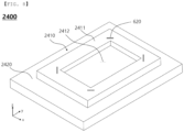
- FIG. 8 is a perspective view of a support unit according to a third embodiment of the present invention.
- a pouch shaping apparatus includes a stripper 2300 and a support unit 2400, wherein the support unit 2400 includes an upper support 2410 and a support plate 2420.
- the pouch shaping apparatus according to the third embodiment is identical to the pouch shaping apparatus described with reference to FIGS. 3 to 5 except that corresponding bead portions are located at facing surfaces of the stripper and the support unit. Hereinafter, therefore, only the bead portions formed at the stripper and the support unit will be described.
- the pouch shaping apparatus includes bead portions formed at the stripper and the support unit. Specifically, bead portions are disposed so as to correspond to each other at a pressing surface of the stripper 2300 that faces the upper surface of the laminate sheet and an upper surface of an upper support frame 2411 that faces the lower surface of the laminate sheet.
- the bead portions include a first bead portion 610 located at the stripper 2300 and a second bead portion 620 located at the support unit 2400.
- a plurality of first bead portions 610 is disposed so as to be spaced apart from each other, and a plurality of second bead portions 620 is disposed so as to be spaced apart from each other.
- first bead portions 610 are disposed at a lower surface of the stripper 2300 so as to be adjacent respectively to four corner parts thereof, and the second bead portions 620 are disposed at an upper surface of the upper support 2410 so as to be adjacent respectively to four corner parts thereof.
- each second bead portion 620 may be an "I"-shaped slit that is located at an upper surface of the upper support frame 2411 of the upper support 2410, that is formed in a straight shape having a predetermined length, and that has a concave recess.
- the "I"-shaped second bead portions 620 are located adjacent respectively to four corner parts of a shaping portion 2412 of the upper support 2410, and are located so as to have an oblique angle with respect to two sides that join each other at a right angle of the upper support frame 2411 constituting the shaping portion 2412.
- the first bead portions 610 are located at the lower surface of the stripper 2300 that faces the support unit 2400. Each of the first bead portions 610 is configured in a convex shape corresponding to a corresponding one of the second bead portions 620, each of which is a concave recess, so as to be inserted into a corresponding one of the second bead portions 620. Here, the first bead portions 610 are disposed at positions corresponding to the second bead portions 620.
- first bead portions 610 are convex and the second bead portions 620 are concave in the above description
- the convex shapes and the concave shapes may be disposed so as to cross each other as long as the first bead portions and the second bead portions are capable of fixing the laminate sheet therebetween.
- each core member was disposed between an upper support and a support plate so as to be adjacent to corner parts of a shaping portion of the upper support.
- the thickness of each core member was 20 um
- the length of a long side of each core member was 50 mm
- the length of a short side of each core member was 30 mm.
- Shaping of a laminate sheet was simulated using a pouch shaping apparatus including the core members, and the maximum displacement of the shaping portion in a direction toward a lower part of a pouch (z-axis direction) was checked.
- Shaping of a laminate sheet was simulated in the same manner as in Example 1 except that core members each having a thickness of 30 um were used, and the maximum displacement of a shaping portion in a direction toward a lower part of a pouch (z-axis direction) was checked.
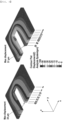
- FIG. 9 shows the results of simulation according to Example 1 and Example 2 of the present invention.
- FIG. 9 only 50% of the support plate cut at a middle part thereof in an overall length direction is shown.
- (a) shows the maximum displacement of Example 1 in the Z-axis direction
- (b) shows the maximum displacement of Example 2 in the Z-axis direction.
- Example 1 In which the thickness of each core member was 20 ⁇ m, the maximum displacement of the laminate sheet in the shaping portion was 34 um.
- Example 2 In which the thickness of each core member was 30 ⁇ m, the maximum displacement of the laminate sheet in the shaping portion was 51 um. It can be seen therefrom that the displacement of the stretched laminate sheet was increased in proportion to the thickness of each core member.
- a laminate sheet was shaped using a pouch shaping apparatus including a two-stage stripper constituted by a first stripper and a second stripper, and the thickness increase rate of the laminate sheet at each corner part of a receiving portion was checked.
- the increased thickness of the laminate sheet was caused by wrinkles formed at each corner part, which means that the smaller the thickness increase rate, the less wrinkles are generated.
- the thickness increase rate of a laminate sheet was checked using the same method as in Example 3 except that a stripper including no second stripper was used, unlike the two-stage stripper of Example 3.
- FIG. 10 shows the results of simulation according to Example 3 of the present invention
- FIG. 11 shows the results of simulation according to Comparative Example 1 of the present invention.
Landscapes
- Engineering & Computer Science (AREA)
- Mechanical Engineering (AREA)
- Chemical & Material Sciences (AREA)
- Chemical Kinetics & Catalysis (AREA)
- Electrochemistry (AREA)
- General Chemical & Material Sciences (AREA)
- Manufacturing & Machinery (AREA)
- Inorganic Chemistry (AREA)
- Sealing Battery Cases Or Jackets (AREA)
- Making Paper Articles (AREA)
Applications Claiming Priority (2)
| Application Number | Priority Date | Filing Date | Title |
|---|---|---|---|
| KR1020210068631A KR102864913B1 (ko) | 2021-05-27 | 2021-05-27 | 파우치 주름을 개선한 파우치 성형 장치 |
| PCT/KR2022/007518 WO2022250482A1 (ko) | 2021-05-27 | 2022-05-26 | 파우치 주름을 개선한 파우치 성형장치 |
Publications (3)
| Publication Number | Publication Date |
|---|---|
| EP4201641A1 true EP4201641A1 (de) | 2023-06-28 |
| EP4201641A4 EP4201641A4 (de) | 2024-03-20 |
| EP4201641B1 EP4201641B1 (de) | 2025-07-23 |
Family
ID=84228934
Family Applications (1)
| Application Number | Title | Priority Date | Filing Date |
|---|---|---|---|
| EP22811673.7A Active EP4201641B1 (de) | 2021-05-27 | 2022-05-26 | Beutelherstellungsvorrichtung für verbesserte beutelfalten |
Country Status (7)
| Country | Link |
|---|---|
| US (1) | US20230373152A1 (de) |
| EP (1) | EP4201641B1 (de) |
| KR (1) | KR102864913B1 (de) |
| CN (1) | CN116670895B (de) |
| ES (1) | ES3049782T3 (de) |
| HU (1) | HUE073287T2 (de) |
| WO (1) | WO2022250482A1 (de) |
Families Citing this family (2)
| Publication number | Priority date | Publication date | Assignee | Title |
|---|---|---|---|---|
| EP4596215B1 (de) * | 2023-04-03 | 2026-04-29 | LG Energy Solution, Ltd. | Beutelherstellungsvorrichtung |
| KR20250012393A (ko) * | 2023-07-17 | 2025-01-24 | 주식회사 엘지에너지솔루션 | 파우치의 포밍장치 |
Family Cites Families (21)
| Publication number | Priority date | Publication date | Assignee | Title |
|---|---|---|---|---|
| US2666951A (en) * | 1951-08-30 | 1954-01-26 | Us Rubber Co | Method and apparatus for drawing plastic sheets |
| JPH11309519A (ja) * | 1998-04-24 | 1999-11-09 | Kawasaki Steel Corp | ステンレス製多角筒ケースの高速深絞り加工方法 |
| KR100586896B1 (ko) * | 2004-07-30 | 2006-06-08 | 주식회사 이스퀘어텍 | 이차전지용 파우치의 성형장치 |
| JP2007061895A (ja) * | 2005-09-02 | 2007-03-15 | Nissan Motor Co Ltd | 金型装置及びパネル成形方法 |
| JP5101906B2 (ja) * | 2007-03-06 | 2012-12-19 | 昭和電工パッケージング株式会社 | 電池ケースの成形方法及び成形装置 |
| KR101208407B1 (ko) * | 2010-10-04 | 2012-12-05 | 삼성전자주식회사 | 목재 필름 및 그 성형 방법 |
| KR102358737B1 (ko) | 2011-10-18 | 2022-02-08 | 가부시키가이샤 한도오따이 에네루기 켄큐쇼 | 발광 장치 |
| KR101477018B1 (ko) * | 2012-05-24 | 2014-12-29 | 주식회사 엘지화학 | 전지케이스 제조 방법 |
| KR20130132093A (ko) * | 2012-05-25 | 2013-12-04 | 주식회사 엘지화학 | 이차 전지용 포장재의 성형 장치 |
| KR101443832B1 (ko) * | 2012-08-07 | 2014-09-23 | 주식회사 엘지화학 | 이차전지 케이스 제조장치 및 제조 방법 |
| EP2994296A1 (de) * | 2013-05-06 | 2016-03-16 | Dow Global Technologies LLC | Formwerkzeug mit integriertem schneiden für verbundwerkstoffe |
| KR102106872B1 (ko) * | 2016-03-07 | 2020-05-06 | 주식회사 엘지화학 | 코일 스프링의 압축량 조정 특성이 향상된 지그 장치 |
| KR102029718B1 (ko) * | 2017-01-19 | 2019-10-08 | 주식회사 엘지화학 | 전지케이스의 수납부 크기에 따라 변형되는 구조의 지그 |
| KR102263480B1 (ko) * | 2017-04-17 | 2021-06-11 | 주식회사 엘지에너지솔루션 | 예비 절단선이 형성된 파우치형 이차전지 |
| KR102261672B1 (ko) * | 2017-04-24 | 2021-06-08 | 주식회사 엘지에너지솔루션 | 말림 방지 가이드 라인이 형성된 전지케이스 및 이의 제조장치 |
| JP6888470B2 (ja) * | 2017-08-04 | 2021-06-16 | トヨタ紡織株式会社 | 金属板材のプレス加工装置及びプレス加工方法 |
| CN207448945U (zh) * | 2017-11-13 | 2018-06-05 | 杭州索凯实业有限公司 | 一种易装卸的模具耐磨板机构 |
| KR102176631B1 (ko) | 2017-11-28 | 2020-11-09 | 주식회사 엘지화학 | 파우치 성형 방법 및 장치 |
| CN208662317U (zh) * | 2018-08-15 | 2019-03-29 | 格力电器(武汉)有限公司 | 一种顶盖成型模具及顶盖成型设备 |
| KR102667401B1 (ko) * | 2018-11-06 | 2024-05-21 | 주식회사 엘지에너지솔루션 | 파우치 성형 장치 및 방법 |
| KR102145494B1 (ko) * | 2018-11-23 | 2020-08-18 | 주식회사 엘지화학 | 파우치 성형장치 및 성형방법, 그를 포함하는 이차전지 제조설비 |
-
2021
- 2021-05-27 KR KR1020210068631A patent/KR102864913B1/ko active Active
-
2022
- 2022-05-26 US US18/027,550 patent/US20230373152A1/en active Pending
- 2022-05-26 EP EP22811673.7A patent/EP4201641B1/de active Active
- 2022-05-26 ES ES22811673T patent/ES3049782T3/es active Active
- 2022-05-26 HU HUE22811673A patent/HUE073287T2/hu unknown
- 2022-05-26 WO PCT/KR2022/007518 patent/WO2022250482A1/ko not_active Ceased
- 2022-05-26 CN CN202280006586.5A patent/CN116670895B/zh active Active
Also Published As
| Publication number | Publication date |
|---|---|
| US20230373152A1 (en) | 2023-11-23 |
| EP4201641A4 (de) | 2024-03-20 |
| EP4201641B1 (de) | 2025-07-23 |
| CN116670895B (zh) | 2026-01-27 |
| KR20220160415A (ko) | 2022-12-06 |
| HUE073287T2 (hu) | 2026-01-28 |
| CN116670895A (zh) | 2023-08-29 |
| ES3049782T3 (en) | 2025-12-18 |
| KR102864913B1 (ko) | 2025-09-26 |
| WO2022250482A1 (ko) | 2022-12-01 |
Similar Documents
| Publication | Publication Date | Title |
|---|---|---|
| EP4201641A1 (de) | Beutelherstellungsvorrichtung für verbesserte beutelfalten | |
| JP5908128B2 (ja) | 二次電池用電池ケース | |
| US10749147B2 (en) | Pouch forming device and method and facility for producing secondary battery comprising the pouch forming device | |
| EP3131133A1 (de) | Batteriemodul | |
| KR20190038094A (ko) | 이차 전지의 파우치 성형 장치 | |
| US20200067034A1 (en) | Crack-Prevention Sealing Block for Pouch-Shaped Secondary Batteries, Pouch-Shaped Battery Case Manufactured Using the Same, and Method of Sealing Pouch-Shaped Battery Case | |
| KR101812272B1 (ko) | 이차 전지용 전극 조립체 제조 방법 | |
| KR102029718B1 (ko) | 전지케이스의 수납부 크기에 따라 변형되는 구조의 지그 | |
| CN110809507A (zh) | 用于二次电池的冲切装置和方法 | |
| US20200153025A1 (en) | Pouch forming method and pouch forming device | |
| KR102254264B1 (ko) | 전극조립체 및 이의 제조 방법 | |
| KR100586896B1 (ko) | 이차전지용 파우치의 성형장치 | |
| US9716253B2 (en) | Battery case for secondary battery | |
| JP2022548229A (ja) | パウチ型電池ケースおよびそれを製造する製造装置、並びにパウチ型二次電池 | |
| CN114846661A (zh) | 用于二次电池的辊压装置 | |
| US12343907B2 (en) | Pouch forming apparatus and method | |
| CN111146369B (zh) | 一种电池冲壳机构和电池制作方法 | |
| KR20130132093A (ko) | 이차 전지용 포장재의 성형 장치 | |
| EP4382280B1 (de) | Beutelherstellungsvorrichtung | |
| KR20150037312A (ko) | 권심 클램프 | |
| EP4585400A1 (de) | Vorrichtung zur herstellung eines beutelartigen batteriegehäuses, damit hergestelltes beutelartiges batteriegehäuse und verfahren zur herstellung eines becherteils | |
| CN115461202A (zh) | 电极切割装置和方法以及包括该电极切割装置的电极制造设备 | |
| JP2022148080A (ja) | 電池モジュール | |
| KR102926933B1 (ko) | 포밍 금형 유닛 | |
| EP4696484A1 (de) | Beutelherstellungsvorrichtung |
Legal Events
| Date | Code | Title | Description |
|---|---|---|---|
| STAA | Information on the status of an ep patent application or granted ep patent |
Free format text: STATUS: THE INTERNATIONAL PUBLICATION HAS BEEN MADE |
|
| PUAI | Public reference made under article 153(3) epc to a published international application that has entered the european phase |
Free format text: ORIGINAL CODE: 0009012 |
|
| STAA | Information on the status of an ep patent application or granted ep patent |
Free format text: STATUS: REQUEST FOR EXAMINATION WAS MADE |
|
| 17P | Request for examination filed |
Effective date: 20230320 |
|
| AK | Designated contracting states |
Kind code of ref document: A1 Designated state(s): AL AT BE BG CH CY CZ DE DK EE ES FI FR GB GR HR HU IE IS IT LI LT LU LV MC MK MT NL NO PL PT RO RS SE SI SK SM TR |
|
| REG | Reference to a national code |
Ref country code: DE Ref legal event code: R079 Free format text: PREVIOUS MAIN CLASS: B29C0051080000 Ipc: B29C0051260000 Ref country code: DE Ref legal event code: R079 Ref document number: 602022018189 Country of ref document: DE Free format text: PREVIOUS MAIN CLASS: B29C0051080000 Ipc: B29C0051260000 |
|
| A4 | Supplementary search report drawn up and despatched |
Effective date: 20240220 |
|
| RIC1 | Information provided on ipc code assigned before grant |
Ipc: B29L 31/34 20060101ALN20240214BHEP Ipc: B29C 51/14 20060101ALN20240214BHEP Ipc: H01M 50/10 20210101ALI20240214BHEP Ipc: H01M 10/04 20060101ALI20240214BHEP Ipc: B29C 51/30 20060101ALI20240214BHEP Ipc: B29C 51/08 20060101ALI20240214BHEP Ipc: B29C 51/26 20060101AFI20240214BHEP |
|
| DAV | Request for validation of the european patent (deleted) | ||
| DAX | Request for extension of the european patent (deleted) | ||
| GRAP | Despatch of communication of intention to grant a patent |
Free format text: ORIGINAL CODE: EPIDOSNIGR1 |
|
| STAA | Information on the status of an ep patent application or granted ep patent |
Free format text: STATUS: GRANT OF PATENT IS INTENDED |
|
| RIC1 | Information provided on ipc code assigned before grant |
Ipc: B29L 31/34 20060101ALN20250415BHEP Ipc: B29C 51/14 20060101ALN20250415BHEP Ipc: H01M 50/10 20210101ALI20250415BHEP Ipc: H01M 10/04 20060101ALI20250415BHEP Ipc: B29C 51/30 20060101ALI20250415BHEP Ipc: B29C 51/08 20060101ALI20250415BHEP Ipc: B29C 51/26 20060101AFI20250415BHEP |
|
| INTG | Intention to grant announced |
Effective date: 20250428 |
|
| GRAS | Grant fee paid |
Free format text: ORIGINAL CODE: EPIDOSNIGR3 |
|
| GRAA | (expected) grant |
Free format text: ORIGINAL CODE: 0009210 |
|
| STAA | Information on the status of an ep patent application or granted ep patent |
Free format text: STATUS: THE PATENT HAS BEEN GRANTED |
|
| P01 | Opt-out of the competence of the unified patent court (upc) registered |
Free format text: CASE NUMBER: APP_25494/2025 Effective date: 20250528 |
|
| AK | Designated contracting states |
Kind code of ref document: B1 Designated state(s): AL AT BE BG CH CY CZ DE DK EE ES FI FR GB GR HR HU IE IS IT LI LT LU LV MC MK MT NL NO PL PT RO RS SE SI SK SM TR |
|
| REG | Reference to a national code |
Ref country code: GB Ref legal event code: FG4D |
|
| REG | Reference to a national code |
Ref country code: CH Ref legal event code: EP |
|
| REG | Reference to a national code |
Ref country code: IE Ref legal event code: FG4D |
|
| REG | Reference to a national code |
Ref country code: DE Ref legal event code: R096 Ref document number: 602022018189 Country of ref document: DE |
|
| REG | Reference to a national code |
Ref country code: NL Ref legal event code: MP Effective date: 20250723 |
|
| PG25 | Lapsed in a contracting state [announced via postgrant information from national office to epo] |
Ref country code: PT Free format text: LAPSE BECAUSE OF FAILURE TO SUBMIT A TRANSLATION OF THE DESCRIPTION OR TO PAY THE FEE WITHIN THE PRESCRIBED TIME-LIMIT Effective date: 20251124 |
|
| PG25 | Lapsed in a contracting state [announced via postgrant information from national office to epo] |
Ref country code: NL Free format text: LAPSE BECAUSE OF FAILURE TO SUBMIT A TRANSLATION OF THE DESCRIPTION OR TO PAY THE FEE WITHIN THE PRESCRIBED TIME-LIMIT Effective date: 20250723 |
|
| REG | Reference to a national code |
Ref country code: AT Ref legal event code: MK05 Ref document number: 1816014 Country of ref document: AT Kind code of ref document: T Effective date: 20250723 |
|
| REG | Reference to a national code |
Ref country code: ES Ref legal event code: FG2A Ref document number: 3049782 Country of ref document: ES Kind code of ref document: T3 Effective date: 20251218 |
|
| PG25 | Lapsed in a contracting state [announced via postgrant information from national office to epo] |
Ref country code: IS Free format text: LAPSE BECAUSE OF FAILURE TO SUBMIT A TRANSLATION OF THE DESCRIPTION OR TO PAY THE FEE WITHIN THE PRESCRIBED TIME-LIMIT Effective date: 20251123 |
|
| PG25 | Lapsed in a contracting state [announced via postgrant information from national office to epo] |
Ref country code: NO Free format text: LAPSE BECAUSE OF FAILURE TO SUBMIT A TRANSLATION OF THE DESCRIPTION OR TO PAY THE FEE WITHIN THE PRESCRIBED TIME-LIMIT Effective date: 20251023 |
|
| REG | Reference to a national code |
Ref country code: LT Ref legal event code: MG9D |
|
| PG25 | Lapsed in a contracting state [announced via postgrant information from national office to epo] |
Ref country code: AT Free format text: LAPSE BECAUSE OF FAILURE TO SUBMIT A TRANSLATION OF THE DESCRIPTION OR TO PAY THE FEE WITHIN THE PRESCRIBED TIME-LIMIT Effective date: 20250723 |
|
| PG25 | Lapsed in a contracting state [announced via postgrant information from national office to epo] |
Ref country code: FI Free format text: LAPSE BECAUSE OF FAILURE TO SUBMIT A TRANSLATION OF THE DESCRIPTION OR TO PAY THE FEE WITHIN THE PRESCRIBED TIME-LIMIT Effective date: 20250723 |
|
| PG25 | Lapsed in a contracting state [announced via postgrant information from national office to epo] |
Ref country code: HR Free format text: LAPSE BECAUSE OF FAILURE TO SUBMIT A TRANSLATION OF THE DESCRIPTION OR TO PAY THE FEE WITHIN THE PRESCRIBED TIME-LIMIT Effective date: 20250723 |
|
| PG25 | Lapsed in a contracting state [announced via postgrant information from national office to epo] |
Ref country code: GR Free format text: LAPSE BECAUSE OF FAILURE TO SUBMIT A TRANSLATION OF THE DESCRIPTION OR TO PAY THE FEE WITHIN THE PRESCRIBED TIME-LIMIT Effective date: 20251024 |
|
| PG25 | Lapsed in a contracting state [announced via postgrant information from national office to epo] |
Ref country code: SE Free format text: LAPSE BECAUSE OF FAILURE TO SUBMIT A TRANSLATION OF THE DESCRIPTION OR TO PAY THE FEE WITHIN THE PRESCRIBED TIME-LIMIT Effective date: 20250723 |
|
| PG25 | Lapsed in a contracting state [announced via postgrant information from national office to epo] |
Ref country code: LV Free format text: LAPSE BECAUSE OF FAILURE TO SUBMIT A TRANSLATION OF THE DESCRIPTION OR TO PAY THE FEE WITHIN THE PRESCRIBED TIME-LIMIT Effective date: 20250723 |
|
| PG25 | Lapsed in a contracting state [announced via postgrant information from national office to epo] |
Ref country code: BG Free format text: LAPSE BECAUSE OF FAILURE TO SUBMIT A TRANSLATION OF THE DESCRIPTION OR TO PAY THE FEE WITHIN THE PRESCRIBED TIME-LIMIT Effective date: 20250723 Ref country code: PL Free format text: LAPSE BECAUSE OF FAILURE TO SUBMIT A TRANSLATION OF THE DESCRIPTION OR TO PAY THE FEE WITHIN THE PRESCRIBED TIME-LIMIT Effective date: 20250723 |
|
| PG25 | Lapsed in a contracting state [announced via postgrant information from national office to epo] |
Ref country code: RS Free format text: LAPSE BECAUSE OF FAILURE TO SUBMIT A TRANSLATION OF THE DESCRIPTION OR TO PAY THE FEE WITHIN THE PRESCRIBED TIME-LIMIT Effective date: 20251023 |
|
| REG | Reference to a national code |
Ref country code: HU Ref legal event code: AG4A Ref document number: E073287 Country of ref document: HU |
|
| PG25 | Lapsed in a contracting state [announced via postgrant information from national office to epo] |
Ref country code: SM Free format text: LAPSE BECAUSE OF FAILURE TO SUBMIT A TRANSLATION OF THE DESCRIPTION OR TO PAY THE FEE WITHIN THE PRESCRIBED TIME-LIMIT Effective date: 20250723 |
|
| PGFP | Annual fee paid to national office [announced via postgrant information from national office to epo] |
Ref country code: GB Payment date: 20260324 Year of fee payment: 5 |
|
| PG25 | Lapsed in a contracting state [announced via postgrant information from national office to epo] |
Ref country code: DK Free format text: LAPSE BECAUSE OF FAILURE TO SUBMIT A TRANSLATION OF THE DESCRIPTION OR TO PAY THE FEE WITHIN THE PRESCRIBED TIME-LIMIT Effective date: 20250723 |
|
| PG25 | Lapsed in a contracting state [announced via postgrant information from national office to epo] |
Ref country code: IT Free format text: LAPSE BECAUSE OF FAILURE TO SUBMIT A TRANSLATION OF THE DESCRIPTION OR TO PAY THE FEE WITHIN THE PRESCRIBED TIME-LIMIT Effective date: 20250723 |
|
| PG25 | Lapsed in a contracting state [announced via postgrant information from national office to epo] |
Ref country code: CZ Free format text: LAPSE BECAUSE OF FAILURE TO SUBMIT A TRANSLATION OF THE DESCRIPTION OR TO PAY THE FEE WITHIN THE PRESCRIBED TIME-LIMIT Effective date: 20250723 |
|
| PG25 | Lapsed in a contracting state [announced via postgrant information from national office to epo] |
Ref country code: EE Free format text: LAPSE BECAUSE OF FAILURE TO SUBMIT A TRANSLATION OF THE DESCRIPTION OR TO PAY THE FEE WITHIN THE PRESCRIBED TIME-LIMIT Effective date: 20250723 Ref country code: SK Free format text: LAPSE BECAUSE OF FAILURE TO SUBMIT A TRANSLATION OF THE DESCRIPTION OR TO PAY THE FEE WITHIN THE PRESCRIBED TIME-LIMIT Effective date: 20250723 |