EP4201638B1 - Blasform zum umformen von kunststoffvorformlingen zu kunststoffbehältnissen mit luftabführung sowie bodenteil für eine blasform - Google Patents
Blasform zum umformen von kunststoffvorformlingen zu kunststoffbehältnissen mit luftabführung sowie bodenteil für eine blasform Download PDFInfo
- Publication number
- EP4201638B1 EP4201638B1 EP22165267.0A EP22165267A EP4201638B1 EP 4201638 B1 EP4201638 B1 EP 4201638B1 EP 22165267 A EP22165267 A EP 22165267A EP 4201638 B1 EP4201638 B1 EP 4201638B1
- Authority
- EP
- European Patent Office
- Prior art keywords
- openings
- base part
- holes
- bottom part
- blow mould
- Prior art date
- Legal status (The legal status is an assumption and is not a legal conclusion. Google has not performed a legal analysis and makes no representation as to the accuracy of the status listed.)
- Active
Links
Images


Classifications
-
- B—PERFORMING OPERATIONS; TRANSPORTING
- B29—WORKING OF PLASTICS; WORKING OF SUBSTANCES IN A PLASTIC STATE IN GENERAL
- B29C—SHAPING OR JOINING OF PLASTICS; SHAPING OF MATERIAL IN A PLASTIC STATE, NOT OTHERWISE PROVIDED FOR; AFTER-TREATMENT OF THE SHAPED PRODUCTS, e.g. REPAIRING
- B29C49/00—Blow-moulding, i.e. blowing a preform or parison to a desired shape within a mould; Apparatus therefor
- B29C49/42—Component parts, details or accessories; Auxiliary operations
- B29C49/48—Moulds
- B29C49/4802—Moulds with means for locally compressing part(s) of the parison in the main blowing cavity
-
- B—PERFORMING OPERATIONS; TRANSPORTING
- B29—WORKING OF PLASTICS; WORKING OF SUBSTANCES IN A PLASTIC STATE IN GENERAL
- B29C—SHAPING OR JOINING OF PLASTICS; SHAPING OF MATERIAL IN A PLASTIC STATE, NOT OTHERWISE PROVIDED FOR; AFTER-TREATMENT OF THE SHAPED PRODUCTS, e.g. REPAIRING
- B29C49/00—Blow-moulding, i.e. blowing a preform or parison to a desired shape within a mould; Apparatus therefor
- B29C49/42—Component parts, details or accessories; Auxiliary operations
- B29C49/62—Venting means
-
- B—PERFORMING OPERATIONS; TRANSPORTING
- B29—WORKING OF PLASTICS; WORKING OF SUBSTANCES IN A PLASTIC STATE IN GENERAL
- B29C—SHAPING OR JOINING OF PLASTICS; SHAPING OF MATERIAL IN A PLASTIC STATE, NOT OTHERWISE PROVIDED FOR; AFTER-TREATMENT OF THE SHAPED PRODUCTS, e.g. REPAIRING
- B29C49/00—Blow-moulding, i.e. blowing a preform or parison to a desired shape within a mould; Apparatus therefor
- B29C49/42—Component parts, details or accessories; Auxiliary operations
- B29C49/48—Moulds
- B29C2049/4879—Moulds characterised by mould configurations
- B29C2049/4892—Mould halves consisting of an independent main and bottom part
-
- B—PERFORMING OPERATIONS; TRANSPORTING
- B29—WORKING OF PLASTICS; WORKING OF SUBSTANCES IN A PLASTIC STATE IN GENERAL
- B29C—SHAPING OR JOINING OF PLASTICS; SHAPING OF MATERIAL IN A PLASTIC STATE, NOT OTHERWISE PROVIDED FOR; AFTER-TREATMENT OF THE SHAPED PRODUCTS, e.g. REPAIRING
- B29C49/00—Blow-moulding, i.e. blowing a preform or parison to a desired shape within a mould; Apparatus therefor
- B29C49/42—Component parts, details or accessories; Auxiliary operations
- B29C49/62—Venting means
- B29C2049/622—Venting means for venting air between preform and cavity, e.g. using venting holes, gaps or patterned moulds
-
- B—PERFORMING OPERATIONS; TRANSPORTING
- B29—WORKING OF PLASTICS; WORKING OF SUBSTANCES IN A PLASTIC STATE IN GENERAL
- B29C—SHAPING OR JOINING OF PLASTICS; SHAPING OF MATERIAL IN A PLASTIC STATE, NOT OTHERWISE PROVIDED FOR; AFTER-TREATMENT OF THE SHAPED PRODUCTS, e.g. REPAIRING
- B29C49/00—Blow-moulding, i.e. blowing a preform or parison to a desired shape within a mould; Apparatus therefor
- B29C49/42—Component parts, details or accessories; Auxiliary operations
- B29C49/62—Venting means
- B29C2049/6271—Venting means for venting blowing medium, e.g. using damper or silencer
-
- B—PERFORMING OPERATIONS; TRANSPORTING
- B29—WORKING OF PLASTICS; WORKING OF SUBSTANCES IN A PLASTIC STATE IN GENERAL
- B29C—SHAPING OR JOINING OF PLASTICS; SHAPING OF MATERIAL IN A PLASTIC STATE, NOT OTHERWISE PROVIDED FOR; AFTER-TREATMENT OF THE SHAPED PRODUCTS, e.g. REPAIRING
- B29C2949/00—Indexing scheme relating to blow-moulding
- B29C2949/07—Preforms or parisons characterised by their configuration
- B29C2949/0715—Preforms or parisons characterised by their configuration the preform having one end closed
-
- B—PERFORMING OPERATIONS; TRANSPORTING
- B29—WORKING OF PLASTICS; WORKING OF SUBSTANCES IN A PLASTIC STATE IN GENERAL
- B29C—SHAPING OR JOINING OF PLASTICS; SHAPING OF MATERIAL IN A PLASTIC STATE, NOT OTHERWISE PROVIDED FOR; AFTER-TREATMENT OF THE SHAPED PRODUCTS, e.g. REPAIRING
- B29C49/00—Blow-moulding, i.e. blowing a preform or parison to a desired shape within a mould; Apparatus therefor
- B29C49/02—Combined blow-moulding and manufacture of the preform or the parison
- B29C49/06—Injection blow-moulding
-
- B—PERFORMING OPERATIONS; TRANSPORTING
- B29—WORKING OF PLASTICS; WORKING OF SUBSTANCES IN A PLASTIC STATE IN GENERAL
- B29K—INDEXING SCHEME ASSOCIATED WITH SUBCLASSES B29B, B29C OR B29D, RELATING TO MOULDING MATERIALS OR TO MATERIALS FOR MOULDS, REINFORCEMENTS, FILLERS OR PREFORMED PARTS, e.g. INSERTS
- B29K2067/00—Use of polyesters or derivatives thereof, as moulding material
- B29K2067/003—PET, i.e. poylethylene terephthalate
-
- B—PERFORMING OPERATIONS; TRANSPORTING
- B29—WORKING OF PLASTICS; WORKING OF SUBSTANCES IN A PLASTIC STATE IN GENERAL
- B29L—INDEXING SCHEME ASSOCIATED WITH SUBCLASS B29C, RELATING TO PARTICULAR ARTICLES
- B29L2031/00—Other particular articles
- B29L2031/712—Containers; Packaging elements or accessories, Packages
- B29L2031/7158—Bottles
Definitions
- the present invention relates to a blow mold for forming plastic preforms into plastic containers with air discharge, as well as to a base part for a blow mold.
- heated plastic preforms are usually introduced into a blow mold, which forms a cavity that serves to expand the plastic preforms into the plastic containers.
- the plastic preforms are usually subjected to a flowable medium, such as compressed air or the product to be filled, against an inner wall of these blow mold parts and thus formed into the plastic containers.
- This inner wall has the contour of the plastic container to be produced.
- the final blowing pressure i.e. the pressure with which the plastic preform is completely formed, is essential for the energy requirement of the blow molding process, so this should be as low as possible.
- the decisive factor for the level of the final blowing pressure is the shape of the last corners of the container, especially in the feet or the standing area, in which counterpressure accumulates during the forming process between the plastic preform and the inside of the blow mold, the container contour, which also includes the base cup or base mold with the contour of the container base.
- the bottom part of the blow mold has vent openings
- the counter pressure is vented in particular through the mold separation gap of the two side parts of the blow mold, the mold separation gap between the two side parts and the base part, as well as the vent openings in the base part.
- the final blowing pressure must be correspondingly high.
- the openings in the base part therefore limit the outflowing volume flow in such a way that a correspondingly higher final blowing pressure is necessary, particularly with comparatively large base part diameters, since all base parts have the same number and size of openings regardless of their diameter or area.
- vent hole pattern remains the same regardless of the hole diameter and is only adapted to the geometry of the contour of the (standing) feet. This means that, for example, a multi-level base with 5 feet always has the same surface area for the vent holes for a bottle diameter of 50 mm up to a bottle diameter of 200 mm or more. However, the surface area of the base geometry increases with the diameter and the height of the base.
- the disadvantage here is that the known floor parts for multi-floors or petaloid floors all have the same number of ventilation holes regardless of their diameter. This is particularly the case with floor parts with a larger diameter, especially diameters of > 65 mm, a higher final blowing pressure is therefore necessary or the venting is worse than with base parts with a smaller diameter.
- the present invention is therefore based on the object of improving the venting of the blow mold or of ensuring sufficient venting regardless of the diameter and thus the size of the base part. This object is achieved according to the invention by the subject matter of the independent claims. Advantageous embodiments and further developments are the subject matter of the subclaims.
- the invention is therefore directed to a blow mold for forming plastic preforms into plastic containers, with at least two blow mold side parts and a base part, which form a cavity within which plastic preforms can be formed into the plastic containers by exposure to a flowable medium, wherein an inner wall of the blow mold side parts and the base part delimiting the cavity has a contour which produces a predetermined shape of the containers to be produced, wherein in at least one section of the base part a plurality of openings are provided which enable a gaseous medium to be discharged during an expansion process of the container.
- a ratio between a surface of the bottom part and a surface of the openings is 3 - 350, preferably 4 - 200 and particularly preferably 5 - 100.
- the ratio between a surface of the base part and a surface of the openings is 25 - 180, preferably 35 - 175 and particularly preferably 47 - 169.
- the preferred or advantageous ratio depends in particular on the size of the bottle or the bottle volume and the shape of the openings.
- a ratio between a surface of the base part and a surface of the openings, which are preferably holes or bores, of 169 is preferred.
- the ratio between a surface of the base part and a surface of the openings is advantageously 145 - 180, preferably 150 - 175 and particularly preferably 155 - 173.
- the ratio between the surfaces of the openings and the base part is always approximately the same, regardless of the diameter of the base part, i.e. that with a larger diameter, the surface area occupied by the openings is correspondingly larger. This can be achieved, for example, by having more openings or larger openings compared to a smaller diameter of the base part. This ensures sufficient venting for any blow mold or container size.
- the surface area of the openings is understood to be the area which the openings in the form of holes, slots or other shapes occupy or have on the base part.
- the following table shows the ratios for diameters from 50 mm to 125 mm for a bottle volume of 0.5 l and openings in the form of holes. It can be seen that the ratios become larger as the base diameter increases, with the number and diameter of the holes or openings remaining the same.
- Bottom-dutch diameter mm Hemisphere surface area of soil m 2 : Bore diameter mm: number of holes per foot Hole surface mm 2 : number of holes per floor Borehole surface per soil m 2 : ratio of borehole to soil surface 50.00 0.0039 1.00 10 0.7854 50 0.000039 100 64.00 0.0064 1.00 10 0.7854 50 0.000039 163.84 65.00 0.0066 1.00 10 0.7854 50 0.000039 169 66.00 0.0068 1.00 10 0.7854 50 0.000039 174.24 67.00 0.0071 1.00 10 0.7854 50 0.000039 179.56 68.00 0.0073 1.00 10 0.7854 50 0.000039 184.96 69.00 0.0075 1.00 10 0.7854 50 0.000039 190.44 70.00 0.0077 1.00 10 0.7854 50 0.000039 196 80.00 0.0101 1.00 10 0.7854 50 0.000039 256 90.00 0.0127 1.00 10 0.7854 50 0.000039 324
- the ratio must be reduced from 400 to approximately 169, ie the surface area of the ventilation openings must be modified and in particular increased from 0.000039 m 2 (39 mm 2 ) to 0.000094 m 2 (94 mm 2 ).
- the hole diameter of the openings can be increased or the number of ventilation openings can be increased.
- a ratio of 169 between a surface area of the base part and a surface area of the openings requires a bore surface area of 0.000023 m 2 (23 mm 2 ) and for a base diameter of 125 mm, a bore surface area of 0.000145 m 2 (145 mm 2 ) is required.
- each foot preferably has ten openings.
- vents for a base diameter of 100 mm, with a desired ratio of 169, this means that instead of ten vents, for example, 24 vents per foot or a total of 120 vents must be provided instead of 50 vents with a diameter of 1 mm, or instead of ten vents with a diameter of 1 mm, ten vents with a diameter of 1.5 mm, or the arrangement of openings of different diameters and therefore instead of ten vent openings with a diameter of 1 mm, eight vent openings with a diameter of 1 mm and one vent opening with a diameter of 4 mm.
- the holes or openings are preferably designed in such a way that they are large enough to allow ventilation or a sufficiently large flow cross-section, but still small enough so that no material from the plastic container is pressed into the openings during forming and no visible and/or noticeable areas are formed on the finished plastic container.
- the openings preferably open into channels which extend through the wall of the blow mold and the base part, so that the flowable medium is preferably discharged from the blow mold via the channels.
- the openings within a wall of the blow mold parts and in particular the base part are preferably connected to channels which serve to discharge the gaseous medium.
- These channels advantageously extend at least partially through the wall of the base part.
- the channels preferably establish a flow connection between an outer wall of the base part and an inner wall of the base part and thus preferably also between an interior of the blow mold and an exterior of the blow mold.
- the diameter of the base part is between 50 mm and 200 mm and the surface area of the openings is between 23 mm 2 and 500 mm 2 and/or the surface area of the base part is between 3900 mm 2 and 65000 mm 2 and the surface area of the openings is between 23 mm 2 and 500 mm 2 .
- Advantageous combinations of diameter of the base part, surface area of the openings and surface area of the base part result in a ratio between surface area of the openings and surface area of the base part of preferably 160 - 175 and particularly preferably almost 169, since such a ratio ensures the lowest compressed air consumption with the greatest possible container quality. This ratio is particularly advantageous for bottle volumes of 0.5 l and when the openings are designed as holes.
- the openings are a plurality of holes and/or slots arranged in the base part and in particular in the areas of the base part which serve to form the standing areas of the finished container.
- a combination of slots and holes is also preferred.
- the openings are designed as slots, for example, a ratio of 169 still provides satisfactory results, but the bottle quality can be further advantageously improved with a ratio of up to 47, so that the ratio between the surface of the openings and the surface of the base part, when the openings are designed as slots, is preferably 40 - 180, preferably 45 - 170 and particularly preferably 47 - 169.
- the ratio between the surface of the openings and the surface of the base part is preferably 30 - 50, preferably 33 - 45 and particularly preferably 35 - 41.
- the holes can preferably be arranged in an orderly manner along at least one and preferably at least two imaginary geometric lines.
- a disordered arrangement of the holes is also conceivable, for example specifically in areas in which the standing areas of the container can be difficult to form, such as very narrow or small areas.
- a slot can also be formed by an arrangement of a plurality of holes or bores, which are preferably arranged along a row or a spline.
- a plurality of holes preferably extends along at least one geometric line.
- the holes are arranged along two or more rows next to each other, so that at least two rows of holes extend next to each other along geometric lines.
- the number of holes of the vent bores in the base part is preferably again dependent on the required or desired vent bore surface in relation to the surface of the base part.
- the holes in the individual rows can preferably be arranged directly next to each other at the same height or offset from each other.
- the holes preferably have a diameter of preferably 0.2 mm to 7 mm, preferably 0.3 mm to 5 mm and particularly preferably 0.5 mm to 4 mm.
- the distances between the individual holes in a row are preferably the same or different. The distance is preferably 0.6x to 2.5x the diameter of the holes and particularly preferably 0.5x to 2x the diameter of the holes.
- the openings and in particular the plurality of holes arranged along a row are preferably guided within a channel in order to remove the gaseous medium more quickly from the base mold.
- the channel preferably has a width multiple of the diameter of the holes.
- each section of a base part has a specific drilling pattern.
- the drilling pattern in a foot and/or a section of the base part can preferably consist of an arrangement of several rows and columns.
- the drilling pattern is arranged centrally within the section of the base part.
- the holes or vent holes preferably all have the same diameter or different diameters. If the diameters are different, the diameters are preferably in a ratio of between 0.25 and 10, preferably between 0.4 and 8 and particularly preferably between 0.5 and 6 to one another.
- the number of holes of the vent holes in the base part is preferably dependent on the required or desired vent hole surface in relation to the surface of the base part.
- the base part is designed to form feet of the plastic container, each foot having a plurality of openings.
- the base part is designed to form feet of the plastic container, each foot having a plurality of openings.
- three to twelve support areas are arranged in the base part to form three to twelve feet of the plastic container.
- the openings are therefore preferably arranged in an area of the base part which serves to form standing areas of the container.
- the openings are therefore preferably arranged in curved sections of the base part.
- each base or each area of the base part used to form base areas of the container has 7 - 35 openings, preferably 8 - 30 openings and particularly preferably 10 - 25 openings.
- a base part with five base areas therefore has 35 - 175 openings, preferably 40 - 150 openings and particularly preferably 50 - 125 openings.
- At least one hole has a diameter of between 0.5 mm and 4 mm, preferably between 0.8 mm and 2 mm.
- the diameters of the openings should particularly preferably be no larger than 2 mm and no smaller than 0.8 mm. In other places, the openings can preferably be up to 5 mm in size in order to achieve rapid venting.
- a distance between two openings arranged next to each other is less than 4 mm, preferably less than 3 mm and preferably less than 2 mm.
- the minimum distance between two bores, from bore edge to bore edge, is preferably 0.2 mm.
- the distance between two openings and in particular holes arranged next to each other is therefore preferably between 0.5 mm and 4 mm, preferably between 0.4 mm and 3 mm and particularly preferably between 0.2 mm and 2 mm.
- At least one slot has a width of between 0.4 mm and 2 mm, preferably between 0.5 mm and 1 mm and particularly preferably between 0.6 mm and 0.8 mm.
- the slots are preferably arranged on the base part by wire erosion, milling, sinking erosion or laser cutting. Depending on the width of the cut or slot, a rectangular cross-section can be created.
- each standing area or each area of the base part which serves to form standing areas of the plastic container has between one and four slots.
- a combination of holes and slots in the base part is also conceivable, with the holes preferably being formed at the ends of the slots or the respective slot. This leads to a reduction in the stresses in the slots.
- a slot therefore preferably runs from hole to hole.
- Ten holes and two slots are preferably formed in each base of the base part. However, there can also preferably be ten holes or fewer than ten holes in one base.
- the present invention is further directed to a base part for a blow mold for forming plastic preforms into plastic containers, wherein the base part has an inner wall with a contour which produces a predetermined base shape of the containers to be produced, wherein in at least one section of the base part a plurality of openings are provided which enable a gaseous medium to be discharged during an expansion process of the container.
- a ratio between a surface of the base part and a surface of the openings is 3 - 350, preferably 4 - 200 and particularly preferably 5 - 100.
- Fig. 1 shows a roughly schematic representation of a device according to the invention for forming plastic preforms 10 into plastic containers 20.
- the plastic preforms 10 are fed via a feed device 55, such as a feed star, and the finished containers are removed from the forming device 50 via a discharge device, such as a discharge star 57.
- the forming device 50 has a rotatable carrier 54 on which a plurality of forming stations 52 are arranged. Each of these forming stations 52 has a blow mold 1.
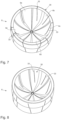
- Fig. 2 shows a schematic view of a blow mold according to the invention.
- This blow mold has two side parts 2, 4 and a base part 6. Together, these two side parts and the base part 6 form a cavity 18 within which the plastic preforms are expanded to form the plastic containers.
- the vent openings described above are located in particular in the base part, but they can also be provided in the side parts, for example in order to be able to better form complicated curvatures of the plastic container.
- the reference numerals 12, 14 refer to carrier shells which carry the side parts 2, 4 and the reference numerals 22, 24 refer to blow mold carriers to which the side parts are each attached (via the carrier shells 12, 14).
- the reference number 60 refers to a vacuum generating device which is only shown schematically. This can be controlled in such a way that it draws air from the interior of the blow mold during a predetermined period of time during the expansion of the plastic preforms.
- Figure 3 shows a schematic representation of a base part 6 according to the invention.
- the base part has five sections 6a, 6b, 6c, 6d, 6e, which each form a standing area or are suitable and intended for forming a standing area of the plastic container 20.
- each stand area a plurality of openings 30 are formed, which are holes here.
- a plurality of openings 30 are formed, which are holes here.
- the Figure 3 a base part 6 with a base diameter of 65 mm with ten holes in each section 6a, 6b, 6c, 6d, 6e, which have a diameter of 1 mm.
- the Figure 4 shows a further schematic representation of a base part 6 according to the invention.
- openings 30 are provided in each section, which consist of a plurality of holes 32.
- each section has 24 holes 32.
- the diameter of the bottom part 6 of the Figure 4 either larger than the diameter of the bottom part of the Figure 3 or the holes here have a smaller diameter than the holes in the Figure 3
- the Figure 4 a base part 6 with a base diameter of 100 mm with 24 holes 32 in each section 6a, 6b, 6c, 6d, 6e, which have a diameter of 1 mm.
- the Figure 5 shows a further schematic representation of a base part 6 according to the invention.
- ten holes 32 are arranged in each section of the base part 6, which, however, have a larger diameter than the holes in the bottom part of the Figure 3 .
- the Figure 5 a base part 6 with a base diameter of 100 mm with ten holes 32 in each section 6a, 6b, 6c, 6d, 6e, which have a diameter of 1.5 mm.
- each section of the base part 6 nine holes 32 are arranged, which have different diameters.
- the Figure 6 a base part 6 with a base diameter of 100 mm with nine holes 32 in each section 6a, 6b, 6c, 6d, 6e, eight holes having a diameter of 1 mm and one hole having a diameter of 4 mm.
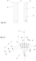
- FIGS 7-9 show further schematic representations of a base part 6 according to the invention.
- openings 30 are arranged in each section 6a, 6b, 6c, 6d, 6e of the base part 6, which are designed here as slots 33.
- a ring is arranged on the base part 6 in addition to improving stability.
- the ring can preferably be arranged on the outer circumference of the base part 6 by shrinking, screwing or welding.
- FIGS. 10-13 show a further embodiment of a base part 6 according to the invention, wherein the openings 30 here consist of a combination of holes 32 or bores and slots 33. It can be seen that holes 32 are arranged at the ends of the slots 33, wherein the slots 33 preferably run from hole 32 to hole 32. In this embodiment, ten holes 32 and two slots 33 are arranged in each section 6a, 6b, 6c, 6d and 6e of the base part 6.
- Figure 14 shows a further schematic representation of a base part 6 according to the invention.
- a plurality of holes are arranged along a row 34 and thus form a type of slot.
- the base part can also have further holes 32.
- the arrangement of the openings 30 in the Figure 14 the arrangement of the openings 30 in the Figure 10 with the difference that the Figure 10 openings designed as slots in the Figure 14 by a plurality of holes arranged along a row 34.
- the reference numerals 6a-6e again identify the individual sections of the base part 6.
- Figure 15 shows a further schematic representation of a base part 6 according to the invention.
- the Figure 15 shows an embodiment in which two rows 34, each with a plurality of holes, are arranged parallel to one another. The arrangement of several such rows would also be conceivable.
- Figure 16 is an exterior view of the Figure 14 shown base part 6. It can be seen that a channel 36 is formed on the outer surface 35 of the base part 6 in the area of the rows 34. The gaseous medium can be discharged from the base part more quickly through this channel.
- the channel 36 is formed with a width that is multiple of the diameter of the holes arranged in the row 34.
- Figure 17 shows a cross-sectional view of the Fig. 14 shown base part 6.
- the plurality of holes arranged in a row 34 can be seen again, as well as the channels 36 arranged on the outer surface 35 of the base part 6, in the area of the rows 34.
- Figure 18 shows a further schematic representation of a base part 6 according to the invention.
- a plurality of holes are arranged along a spline 38.
- This arrangement of the openings 30 corresponds to the arrangement of the openings 30 in the Figure 11 with the difference that the Figure 11 openings formed as curved slots in the Figure 18 by a plurality of holes arranged along a spline 38.
- Figure 19 is an exterior view of the Figure 18 shown base part 6.
- the channel 36 can be seen again, which corresponds in shape to the spline 38 formed by the holes.
- Figure 20 shows a schematic representation of an arrangement of holes 32 in a row 34.
- there are two rows 34 of holes 32 whereby the holes 32 are arranged at the same height and directly next to each other.
- two rows 34 of holes 32 can also be seen, whereby the holes 32 are arranged offset from each other.
- the small arrows indicate the distances between the holes, which can be the same or different.
- Figure 21 shows an example of a drilling pattern 40 of a section of the base part.
- the drilling pattern is perpendicular to a surface of the base geometry of the base and is preferably arranged centrally on the base of the base part with respect to a center point M of the base part.
- the individual holes 32 are arranged here in particular in several columns 44 and rows 42.
- the angles A and B depend on the width of the base.
- the angle A which extends from the center point M to the respective adjacent column, is preferably between 2° and 60°, preferably between 5° and 35° and particularly preferably between 10° and 25°.
- the angle B between two columns arranged next to one another is preferably between 0.5° and 30°, preferably between 0.8° and 25° and particularly preferably between 1° and 20°.
- the angle A can preferably also depend on the diameter of the container or be in a ratio X to the container diameter.
- the ratio X can preferably be between 0 and 10.
- the reference symbol R indicates the radius of the base part and the reference symbols C-E indicate the distances between the holes along a row or column 44.
- the radius R is preferably either in a ratio RD to the container diameter or in a ratio RS to a standing circle diameter of the base.
- the ratio RD can be between 0 and 1, preferably between 0.25 and 0.90.
- the ratio RS can be between 0 and 2, preferably between 0.5 and 1.5.
- Figure 22 shows another example of a drilling pattern 40 of a section of the base part.
- the individual holes 23 are again arranged in several columns 44 and rows 42, whereby the columns 44 are marked with the numbers 20-28 and the rows with the numbers 1-10.
- the columns 44 are preferably arranged in a radial direction to a center point M of the base part and the rows 42 in the circumferential direction of the base part.
- the individual holes 32 within a drilling pattern 40 can preferably have the same diameter or a different diameter. If the holes 32 are of different sizes, they are preferably in a ratio BD to one another which is between 0.25 and 10, preferably between 0.5 and 6.
- the Figures 23-26 show further exemplary drilling patterns 40 of a section of the base part.
- a large number of holes 32 are arranged in several columns 44 and rows 42.
- the respective drilling pattern 40 can consist of any number of holes 32, which have either the same or different diameters.
Landscapes
- Engineering & Computer Science (AREA)
- Manufacturing & Machinery (AREA)
- Mechanical Engineering (AREA)
- Moulds For Moulding Plastics Or The Like (AREA)
- Containers Having Bodies Formed In One Piece (AREA)
- Blow-Moulding Or Thermoforming Of Plastics Or The Like (AREA)
Description
- Die vorliegende Erfindung bezieht sich auf eine Blasform zum Umformen von Kunststoffvorformlingen zu Kunststoffbehältnissen mit Luftabführung sowie auf ein Bodenteil für eine Blasform. Dabei werden üblicherweise erwärmte Kunststoffvorformlinge in eine Blasform eingebracht, welche einen Hohlraum ausbildet, der zur Expansion der Kunststoffvorformlinge zu den Kunststoffbehältnissen dient. Innerhalb dieses Hohlraums werden die Kunststoffvorformlinge üblicherweise mit einem fließfähigen Medium, wie insbesondere Druckluft oder dem abzufüllenden Produkt, gegen eine Innenwandung dieser Blasformteile beaufschlagt und so zu den Kunststoffbehältnissen geformt. Diese Innenwandung weist dabei die Kontur des herzustellenden Kunststoffbehältnisses auf.
- Weitere gattungsgemäße Blasformen und Bodenteilen sind in den Patentschriften
DE102013226906A1 ,US2017/173845A1 ,US2016/332356A1 ,US2018/043605A1 ,US2015/061196A1 undUS2016/325483A1 beschrieben. - Der Fertigblasdruck, d.h. der Druck, mit dem der Kunststoffvorformling vollständig ausgeformt wird, ist dabei wesentlich für den Energiebedarf des Blasformvorgangs, so dass dieser möglichst gering sein sollte. Entscheidend für die Höhe des Fertigblasdrucks ist dabei insbesondere die Ausprägung der letzten Ecken des Behältnisses, insbesondere in den Füßchen bzw. dem Standbereich, in welchen sich bei der Umformung zwischen dem Kunststoffvorformling und der Blasforminnenseite, der Behälterkontur, zu welcher auch die Bodentasse bzw. Bodenform mit der Kontur des Behälterbodens gehört, Gegendruck sammelt.
- Um diesen Gegendruck zu entlasten, weist das Bodenteil der Blasform Entlüftungsöffnungen auf. Der Gegendruck wird dabei insbesondere durch die Formtrennspalte der beiden Seitenteile der Blasform, dem Formtrennspalt zwischen den beiden Seitenteilen und dem Bodenteil, sowie den Entlüftungsöffnungen in dem Bodenteil entlüftet. Wenn der Kunststoffvorformling so weit aufgeblasen bzw. umgeformt ist, dass sich die entwickelnde Blase des Kunststoffvorformlings in dem Bodenteil befindet, kann die Entlüftung in dem Bodenteil nur noch über die Entlüftungsöffnungen erfolgen.
- Erfolgt hier keine oder nur eine unzureichende Entlüftung, muss der Fertigblasdruck entsprechend hoch sein. Die Öffnungen in dem Bodenteil begrenzen demnach den abfließenden Volumenstrom derart, dass insbesondere bei vergleichsweise großen Bodenteildurchmessern ein entsprechend höherer Fertigblasdruck notwendig ist, da alle Bodenteile unabhängig von ihrem Durchmesser bzw. ihrer Fläche die gleiche Anzahl und Größe von Öffnungen aufweisen.
- Bei einer internen Untersuchung der Anmelderin der Reduzierung des Fertigblasdrucks beim Streckblasen von Kunststoffbehältern bei verschiedenen Volumina wurde festgestellt, dass sich der Blasdruck bei den kleineren Behältern leichter reduzieren lässt als bei den größeren. Es wurde außerdem festgestellt, dass das "Entlüftungsbohrbild" unabhängig von den Bohrungsdurchmesser gleichbleibt und nur an die Geometrie der Kontur der (Stand)Füße angepasst wird. Das bedeutet, dass beispielsweise ein Mehrfußboden mit 5 Füssen bei einem Flaschendurchmesser von 50 mm bis zu einem Flaschendurchmesser von 200 mm, oder mehr, immer die gleiche Oberfläche bei den Entlüftungsbohrungen hat. Die Oberfläche der Bodengeometrie nimmt allerdings mit dem Durchmesser und der Bodenhöhe zu.
- Aus dem internen Stand der Technik der Anmelderin ist es demnach bekannt, dass in dem Bodenteil einer Blasform, welches insbesondere die Standfüße des Behältnisses ausbildet, eine Anzahl von Löchern bzw. Bohrungen oder Schlitzen zur Entlüftung von Mehrfußböden (mehrere Bereiche zur Ausbildung von Standfüßen an dem Behältnis) bzw. Petaloidböden vorhanden sind. Im internen Stand der Technik der Anmelderin sind dabei beispielsweise pro Fuß acht Bohrungen mit 1 mm und zwei Bohrungen mit 0,8 mm vorhanden. Somit kommt man bei einem Boden mit fünf Füßen (Petaloidboden) auf eine Gesamtanzahl von 40 Bohrungen mit 1 mm und zehn Bohrungen mit 0,8 mm und demnach insgesamt 50 Bohrungen.
- Dabei ist es nachteilig, dass die bekannten Bodenteile für Mehrfußböden bzw. Petaloidböden unabhängig von ihrem Durchmesser alle die gleiche Anzahl an Entlüftungsbohrungen aufweisen. Insbesondere bei Bodenteilen mit größerem Durchmesser, insbesondere Durchmessern von > 65 mm, ist daher ein höherer Fertigblasdruck notwendig bzw. die Entlüftung ist schlechter als bei Bodenteilen mit kleinerem Durchmesser.
- Der vorliegenden Erfindung liegt daher die Aufgabe zugrunde, die Entlüftung der Blasform zu verbessern bzw. unabhängig von dem Durchmesser und damit der Größe des Bodenteils eine ausreichende Entlüftung sicherzustellen. Diese Aufgabe wird erfindungsgemäß durch die Gegenstände der unabhängigen Ansprüche erreicht. Vorteilhafte Ausführungsformen und Weiterbildungen sind Gegenstand der Unteransprüche.
- Die Erfindung ist daher auf eine Blasform zum Umformen von Kunststoffvorformlingen zu Kunststoffbehältnissen gerichtet, mit wenigstens zwei Blasformseitenteilen und einem Bodenteil, welche einen Hohlraum ausbilden, innerhalb dessen Kunststoffvorformlinge durch Beaufschlagung mit einem fließfähigen Medium zu den Kunststoffbehältnissen umformbar sind, wobei eine den Hohlraum begrenzende Innenwandung der Blasformseitenteile und des Bodenteils eine Kontur aufweist, welche eine vorgegebene Gestalt der herzustellenden Behältnisse erzeugt, wobei in wenigstens einem Abschnitt des Bodenteils eine Vielzahl von Öffnungen vorgesehen ist, welche ein Abführen eines gasförmigen Mediums während eines Expansionsvorgangs des Behältnisses ermöglichen.
- Erfindungsgemäß liegt ein Verhältnis zwischen einer Oberfläche des Bodenteils und einer Oberfläche der Öffnungen bei 3 - 350, bevorzugt bei 4 - 200 und besonders bevorzugt bei 5 -100.
- Vorteilhaft liegt das Verhältnis zwischen einer Oberfläche des Bodenteils und einer Oberfläche der Öffnungen bei 25 - 180, bevorzugt bei 35 - 175 und besonders bevorzugt bei 47 - 169. Das bevorzugte bzw. vorteilhafte Verhältnis hängt dabei insbesondere von der Größe der Flasche bzw. dem Flaschenvolumen und der Form der Öffnungen ab.
- Beispielsweise wird bei einem Flaschenvolumen von 0,5 l ein Verhältnis zwischen einer Oberfläche des Bodenteils und einer Oberfläche der Öffnungen, bei welchen es sich bevorzugt um Löcher oder Bohrungen handelt von 169 bevorzugt. Vorteilhaft liegt bei diesem Beispiel das Verhältnis dabei zwischen einer Oberfläche des Bodenteils und einer Oberfläche der Öffnungen bei 145 - 180, bevorzugt bei 150 - 175 und besonders bevorzugt bei 155 - 173.
- Es wird demnach erfindungsgemäß vorgeschlagen, dass das Verhältnis zwischen den Oberflächen von Öffnungen und Bodenteil, unabhängig von dem Durchmesser des Bodenteils immer annähernd gleich ist d.h., dass mit einem größeren Durchmesser entsprechend auch die Oberfläche, welche die Öffnungen einnehmen größer ist. Dies kann beispielsweise durch, im Vergleich zu einem kleineren Durchmesser des Bodenteils, mehrere Öffnungen oder auch größere Öffnungen erreicht werden. Hierdurch kann bei jeder Blasform- bzw. Behältnisgröße eine ausreichende Entlüftung sichergestellt werden.
- Unter der Oberfläche der Öffnungen wird dabei die Fläche verstanden, welche die Öffnungen in Form von Löchern, Schlitzen oder anderen beliebigen Formen auf dem Bodenteil einnehmen bzw. aufweisen.
- Es wurde bei internen Untersuchungen der Anmelderin festgestellt, dass das Verhältnis zwischen Oberfläche der Bodengeometrie und der Oberfläche der Öffnungen und insbesondere Entlüftungsöffnungen bzw. Entlüftungsbohrungen einen Einfluss auf die Entlüftung hat.
- Die folgende Tabelle zeigt die Verhältnisse für die Durchmesser von 50 mm bis 125 mm bei einem Flaschenvolumen von 0,5 l und Öffnungen in Form von Löchern. Es ist zu erkennen, dass die Verhältnisse, bei gleichbleibender Anzahl und Durchmesser der Bohrungen bzw. Öffnungen, mit zunehmendem Bodendurchmesser immer größer werden.
Boden-dutchmesser mm: Halbkugel- oberfläche Boden m2: Bohrungs- durchmesser mm: Anzahl Bohrungen pro Fuß Bohrungoberfläche mm2: Anzahl Bohrungen pro Boden Bohrung- oberfläche pro Boden m2: Verhältnis Bohrungs- zu Boden- oberfläche 50,00 0,0039 1,00 10 0,7854 50 0,000039 100 64,00 0,0064 1,00 10 0,7854 50 0,000039 163,84 65,00 0,0066 1,00 10 0,7854 50 0,000039 169 66,00 0,0068 1,00 10 0,7854 50 0,000039 174,24 67,00 0,0071 1,00 10 0,7854 50 0,000039 179,56 68,00 0,0073 1,00 10 0,7854 50 0,000039 184,96 69,00 0,0075 1,00 10 0,7854 50 0,000039 190,44 70,00 0,0077 1,00 10 0,7854 50 0,000039 196 80,00 0,0101 1,00 10 0,7854 50 0,000039 256 90,00 0,0127 1,00 10 0,7854 50 0,000039 324 100,00 0,0157 1,00 10 0,7854 50 0,000039 400 110,00 0,0190 1,00 10 0,7854 50 0,000039 484 120,00 0,0226 1,00 10 0,7854 50 0,000039 576 125,00 0,0245 1,00 10 0,7854 50 0,000039 625 - Bei den internen Untersuchungen und Versuchen der Anmelderin hat sich gezeigt, dass, ausgehend von diesem Beispiel, ein Kunststoffbehältnis mit einem Durchmesser von 65 mm sehr gute Fertigblasdruckergebnisse erzielt hat. Es wurde daher das Verhältnis zwischen der Oberfläche der Bodengeometrie und der Oberfläche der Entlüftungsöffnungen für einen Versuchsbehälter mit einem Durchmesser von 100 mm auf das Verhältnis des Behälterdurchmessers von 65 mm angepasst.
- Hierzu muss, wie aus der Tabelle hervorgeht, das Verhältnis von 400 auf ca. 169 reduziert werden, d.h. die Oberfläche der Entlüftungsöffnungen muss verändert werden und insbesondere vergrößert werden, und zwar von 0,000039 m2 (39 mm2) auf 0,000094 m2 (94 mm2).
- Um die Fläche der Entlüftungsöffnungen zu verändern und insbesondere wie im beschriebenen Beispiel zu vergrößern, gibt es verschiedene Möglichkeiten. Bevorzugt kann hierzu der Bohrungsdurchmesser der Öffnungen vergrößert werden oder die Anzahl der Entlüftungsöffnungen erhöht werden. Auch die Verwendung einer Kombination aus verschiedenen Öffnungsdurchmessern oder eine quadratische Geometrie oder eine rechteckige Geometrie oder Kombinationen aus Bohrungen mit rechteckigen Geometrien z.B. Schlitze wäre bevorzugt denkbar. Da jeder Fuß bzw. Standbereich des Bodenteils zwei Flanken aufweist, sollte bevorzugt, um eine symmetrische Aufteilung zu erhalten, immer eine Gerade Zahl an den Entlüftungsbohrungen pro Fuß vorhanden sein.
- Bei einem Bodendurchmesser von 50 mm ist für ein Verhältnis von 169 zwischen einer Oberfläche des Bodenteils und einer Oberfläche der Öffnungen beispielsweise eine Bohrungsoberfläche von 0,000023 m2 (23 mm2) notwendig und für einen Bodendurchmesser von 125 mm eine Bohrungsoberfläche von 0,000145 m2 (145 mm2).
- Wie erwähnt, ist es aus dem internen Stand der Technik der Anmelderin bekannt, dass bei einem Bodenteil mit fünf Füßen, jeder Fuß bevorzugt zehn Öffnungen aufweist.
- Für einen Bodendurchmesser von 100 mm, mit einem gewünschten Verhältnis von 169, bedeutet dies, dass anstelle von zehn Entlüftungsöffnungen beispielswiese 24 Entlüftungsöffnungen pro Fuß bzw. insgesamt 120 Öffnungen anstelle von 50 Öffnungen mit einem Durchmesser von 1 mm vorgesehen werden müssen, oder anstelle von zehn Entlüftungsöffnungen mit einem Durchmesser von 1 mm, zehn Entlüftungsöffnungen mit einem Durchmesser von 1,5 mm, oder die Anordnung von Öffnungen mit unterschiedlichen Durchmessern und daher anstelle von zehn Entlüftungsöffnungen mit einem Durchmesser von 1 mm, acht Entlüftungsöffnungen mit einem Durchmesser von 1 mm und eine Entlüftungsöffnung mit einem Durchmesser von 4 mm.
- Die Bohrungen bzw. Öffnungen sind dabei bevorzugt derart zu gestalten, dass diese einerseits groß genug sind, um eine Entlüftung zu ermöglichen bzw. einen ausreichend großen Strömungsquerschnitt zu erlauben, jedoch noch so klein, so dass kein Material des Kunststoffbehältnisses während der Umformung in die Öffnungen hineingedrückt wird und sich auch keine sicht- und/oder spürbaren Bereiche auf dem fertigen Kunststoffbehältnis ausbilden.
- Bevorzugt münden die Öffnungen in Kanäle, welche sich durch die Wandung der Blasform und des Bodenteils hindurch erstrecken, so dass bevorzugt eine Abführung des fließfähigen Mediums aus der Blasform über die Kanäle erfolgt. Demnach schließen sich bevorzugt an die Öffnungen innerhalb einer Wandung der Blasformteile und insbesondere des Bodenteils Kanäle an, welche zur Abführung des gasförmigen Mediums dienen. Vorteilhaft erstrecken sich diese Kanäle wenigstens teilweise durch die Wandung des Bodenteils hindurch. Bevorzugt stellen die Kanäle eine Strömungsverbindung zwischen einer Außenwand des Bodenteils und einer Innenwand des Bodenteils her und damit bevorzugt auch zwischen einem Innenraum der Blasform und einem Außenraum der Blasform.
- Bei einer bevorzugten Ausführungsform liegt ein Durchmesser des Bodenteils zwischen 50 mm und 200 mm und die Oberfläche der Öffnungen zwischen 23 mm2 und 500 mm2 und/oder die Oberfläche des Bodenteils zwischen 3900 mm2 und 65000 mm2 und die Oberfläche der Öffnungen zwischen 23 mm2 und 500 mm2. Vorteilhaft sind dabei Kombinationen von Durchmesser des Bodenteils, Oberfläche der Öffnungen und Oberfläche des Bodenteils, welche ein Verhältnis zwischen Oberfläche der Öffnungen und Oberfläche des Bodenteils von bevorzugt 160 - 175 und besonders bevorzuge nahezu 169 ergeben, da ein derartiges Verhältnis den geringsten Druckluftverbrauch bei größtmöglicher Behälterqualität sicherstellt. Dieses Verhältnis ist dabei insbesondere vorteilhaft für Flaschenvolumen von 0,5 l und der Ausbildung der Öffnungen als Löcher.
- Bei einer weiteren bevorzugten Ausführungsform handelt es sich bei den Öffnungen um eine Vielzahl von Löchern und/oder Schlitzen, welche in dem Bodenteil und insbesondere den Bereichen des Bodenteils, welche zur Ausbildung der Standbereiche des fertigen Behältnisses dienen, angeordnet ist. Bevorzugt ist dabei auch eine Kombination aus Schlitzen und Löchern.
- Sind die Öffnungen beispielsweise als Schlitze ausgeführt liefert ein Verhältnis von 169 zwar weiterhin zufriedenstellende Ergebnisse, allerdings lässt sich die Flaschenqualität bei einem Verhältnis bis 47 weiter vorteilhaft verbessern, so dass das Verhältnis zwischen der Oberfläche der Öffnungen und der Oberfläche des Bodenteils, wenn die Öffnungen als Schlitze ausgebildet sind, bevorzugt bei 40 - 180, bevorzugt bei 45 - 170 und besonders bevorzugt bei 47 - 169 liegt.
- Sind die Öffnungen als eine Kombination aus Schlitzen und Löchern ausgebildet liegt das Verhältnis zwischen der Oberfläche der Öffnungen und der Oberfläche des Bodenteils bevorzugt bei 30 - 50, bevorzugt bei 33 - 45 und besonders bevorzugt bei 35 - 41.
- Die Löcher können dabei bevorzugt geordnet entlang von wenigstens einer und bevorzugt wenigstens zwei gedachten geometrischen Linien angeordnet sein. Denkbar ist bevorzugt aber auch eine ungeordnete Anordnung der Löcher, beispielswiese gezielt in Bereichen, in welchen die Standbereiche des Behältnisses schwer ausgebildet werden können, wie beispielsweise sehr enge oder kleine Bereiche.
- Bevorzugt kann ein Schlitz auch durch eine Anordnung einer Vielzahl von Löchern bzw. Bohrungen ausgebildet werden, welche bevorzugt entlang einer Reihe oder eines Splines angeordnet sind. Eine Vielzahl von Löchern erstreckt sich dabei bevorzugt entlang wenigstens einer geometrischen Linie. Bevorzugt werden die Löcher dabei entlang zweier oder mehrerer Reihen nebeneinander angeordnet, sodass sich wenigstens zwei Reihen von Löchern nebeneinander entlang geometrischer Linien erstrecken. Die Anzahl der Löcher der Entlüftungsbohrungen in dem Bodenteil ist dabei bevorzugt wieder abhängig von der benötigten oder gewünschten Entlüftungsbohrungsoberfläche im Verhältnis zur Oberfläche des Bodenteils.
- Die Löcher der einzelnen Reihen können bevorzugt direkt nebeneinander auf gleicher Höhe angeordnet sein oder versetzt zueinander. Die Löcher weisen bevorzugt einen Durchmesser von bevorzugt 0,2 mm bis 7 mm, bevorzugt 0,3 mm bis 5 mm und besonders bevorzugt von 0,5 mm bis 4 mm auf. Die Abstände der einzelnen Löcher in einer Reihe zueinander sind bevorzugt gleich oder unterschiedlich. Bevorzugt liegt der Abstand bei 0,6xbis 2,5x dem Durchmesser der Löcher und besonders bevorzugt bei 0,5x bis 2x dem Durchmesser der Löcher.
- An einer Außenseite der Bodenform werden die Öffnungen und insbesondere die entlang einer Reihe angeordnete Vielzahl von Löchern bevorzugt innerhalb eines Kanals geführt, um das gasförmige Medium schneller aus der Bodenform abzuführen. Der Kanal weist dabei, bezogen auf einen Durchmesser der Löcher, eine bevorzugt vielfache Breite auf.
- Bevorzugt weist jeder Abschnitt eines Bodenteils ein spezifisches Bohrbild auf. Das Bohrbild in einem Fuß und/oder einem Abschnitt des Bodenteils kann bevorzugt aus einer Anordnung mehrerer Zeilen und Spalten bestehen. Bevorzugt ist das Bohrbild mittig innerhalb des Abschnitts des Bodenteils angeordnet. Die Löcher bzw. Entlüftungsbohrung weisen dabei bevorzugt alle den gleichen Durchmesser auf oder unterschiedliche Durchmesser. Bei unterschiedlichen Durchmessern stehen die Durchmesser bevorzugt in einem Verhältnis zwischen 0,25 und 10, bevorzugt zwischen 0,4 und 8 und besonders bevorzugt zwischen 0,5 und 6 zueinander. Auch hier ist die Anzahl der Löcher der Entlüftungsbohrungen in dem Bodenteil bevorzugt wieder abhängig von der benötigten oder gewünschten Entlüftungsbohrungsoberfläche im Verhältnis zur Oberfläche des Bodenteils.
- In einer weiteren bevorzugten Ausführungsform ist das Bodenteil zur Ausbildung von Standfüßen des Kunststoffbehältnisses ausgebildet, wobei jeder Standfuß eine Vielzahl von Öffnungen aufweist. Bevorzugt sind dabei in dem Bodenteil drei bis zwölf Standbereiche zur Ausbildung von drei bis zwölf Standfüßen des Kunststoffbehältnisses angeordnet.
- Die Öffnungen sind demnach bevorzugt in einem Bereich des Bodenteils angeordnet, der zur Ausbildung von Standbereichen des Behältnisses dient. Bevorzugt sind die Öffnungen daher in gekrümmten Abschnitten des Bodenteils angeordnet.
- In einer bevorzugten Ausführungsform weist jeder Standfuß bzw. jeder zur Ausbildung von Standbereichen des Behältnisses dienende Bereich des Bodenteils 7 - 35 Öffnungen, bevorzugt 8 - 30 Öffnungen und besonders bevorzugt 10 - 25 Öffnungen auf. Insgesamt weist ein Bodenteil mit fünf Standbereichen demnach 35 - 175 Öffnungen, bevorzugt 40 - 150 Öffnungen und besonders bevorzugt 50 - 125 Öffnungen auf.
- Bei einer weiteren bevorzugten Ausführungsform weist wenigstens ein Loch einen Durchmesser auf, der zwischen 0,5 mm und 4 mm, bevorzugt zwischen 0,8 mm und 2 mm liegt. Besonders bevorzugt sollten, um eine zu starke Ausprägung der Entlüftungsöffnungen an Sichtflächen oder Funktionsfläche am Boden zu vermeiden, die Durchmesser der Öffnungen nicht größer sein als 2 mm, und nicht kleiner als 0,8 mm. An anderen Stellen können die Öffnungen bevorzugt bis zu 5 mm groß sein, um ein schnelles Entlüften zu realisieren.
- Bevorzugt ist ein Abstand zwischen zwei nebeneinander angeordneten Öffnungen kleiner als 4 mm, bevorzugt kleiner als 3 mm und bevorzugt kleiner als 2 mm. Insbesondere muss dabei genügend Material zwischen zwei nebeneinander gelegenen Öffnungen und insbesondere Löchern oder Bohrungen sein, so dass diese nicht ineinanderlaufen bzw. ineinander übergehen. Der minimale Abstand zwischen zwei Bohrungen, von Bohrungsrand zu Bohrungsrand ist, ist dabei bevorzugt 0,2 mm. Der Abstand zwischen zwei nebeneinander angeordneten Öffnungen und insbesondere Löchern ist demnach bevorzugt zwischen 0,5 mm und 4 mm, bevorzugt zwischen 0,4 mm und 3 mm und besonders bevorzugt zwischen 0,2 mm und 2 mm.
- In einer weiteren bevorzugten Ausführungsform weist wenigstens ein Schlitz eine Breite auf, die zwischen 0,4 mm und 2 mm, bevorzugt zwischen 0,5 mm und 1 mm und besonders bevorzugt zwischen 0,6 mm und 0,8mm liegt. Die Schlitze werden dabei bevorzugt durch Drahterodieren, Fräsen, Senkerodieren oder Laserschneiden an dem Bodenteil angeordnet. Je nach Schnitt- bzw. Schlitzbreite kann dabei ein rechteckiger Querschnitt erstellt werden.
- Bevorzugt weist jeder Standbereich bzw. jeder Bereich des Bodenteils, welcher zur Ausbildung von Standbereichen des Kunststoffbehältnisses dient, zwischen ein bis vier Schlitzen auf.
- Denkbar ist bevorzugt auch eine Kombination aus Löchern und Schlitzen in dem Bodenteil, wobei die Löcher bevorzugt jeweils an den Enden der Schlitze bzw. des jeweiligen Schlitzes ausgebildet sind. Dies führ zu einer Verringerung der Spannungen in den Schlitzen. Ein Schlitz verläuft demnach bevorzugt von Bohrung zu Bohrung. Bevorzugt sind in jedem Standfuß des Bodenteils zehn Bohrungen und zwei Schlitze ausgebildet. Bevorzugt können aber auch als zehn Bohrungen oder weniger als zehn Bohrungen in einem Standfuß vorhanden sein.
- Die vorliegende Erfindung ist weiter auch auf ein Bodenteil für eine Blasform zum Umformen von Kunststoffvorformlingen zu Kunststoffbehältnissen gerichtet, wobei das Bodenteil eine Innenwandung mit einer Kontur aufweist, welche eine vorgegebene Bodengestalt der herzustellenden Behältnisse erzeugt, wobei in wenigstens einem Abschnitt des Bodenteils eine Vielzahl von Öffnungen vorgesehen ist, welche ein Abführen eines gasförmigen Mediums während eines Expansionsvorgangs des Behältnisses ermöglichen.
- Erfindungsgemäß liegt dabei ein Verhältnis zwischen einer Oberfläche des Bodenteils und einer Oberfläche der Öffnungen bei 3 - 350, bevorzugt bei 4 - 200 und besonders bevorzugt bei 5 - 100.
- Weitere Vorteile und Ausführungsformen ergeben sich aus den beigefügten Zeichnungen. Darin zeigt:
- Fig. 1
- eine grob schematische Darstellung einer Vorrichtung zum Umformen von Kunststoffvorformlingen zu Kunststoffbehältnissen;
- Fig. 2
- eine Darstellung einer Blasstation mit Blasform zum Umformen von Kunststoffvorformlingen zu Kunststoffbehältnissen;
- Fig. 3
- eine schematische Darstellung eines erfindungsgemäßen Bodenteils mit Entlüftungslöchern;
- Fig. 4
- eine weitere schematische Darstellung eines erfindungsgemäßen Bodenteils mit Entlüftungslöchern;
- Fig. 5
- eine weitere schematische Darstellung eines erfindungsgemäßen Bodenteils mit Entlüftungslöchern;
- Fig. 6
- eine weitere schematische Darstellung eines erfindungsgemäßen Bodenteils mit Entlüftungslöchern;
- Fig. 7
- eine schematische Darstellung eines erfindungsgemäßen Bodenteils mit Schlitzen;
- Fig. 8
- eine weitere schematische Darstellung eines erfindungsgemäßen Bodenteils mit Schlitzen;
- Fig. 9
- eine weitere schematische Darstellung eines erfindungsgemäßen Bodenteils mit Schlitzen;
- Fig. 10
- eine schematische Darstellung eines erfindungsgemäßen Bodenteils mit einer Kombination aus Entlüftungslöchern und Schlitzen;
- Fig. 11
- eine weitere schematische Darstellung eines erfindungsgemäßen Bodenteils mit einer Kombination aus Entlüftungslöchern und Schlitzen;
- Fig. 12
- eine weitere schematische Darstellung eines erfindungsgemäßen Bodenteils mit einer Kombination aus Entlüftungslöchern und Schlitzen;
- Fig. 13
- eine weitere schematische Darstellung eines erfindungsgemäßen Bodenteils mit einer Kombination aus Entlüftungslöchern und Schlitzen;
- Fig. 14
- eine weitere schematische Darstellung eines erfindungsgemäßen Bodenteils;
- Fig. 15
- eine weitere schematische Darstellung eines erfindungsgemäßen Bodenteils;
- Fig. 16
- eine Außenansicht des in
Fig. 14 dargestellten Bodenteils; - Fig. 17
- eine Schnittdarstellung des in
Fig. 14 dargestellten Bodenteils; - Fig. 18
- eine weitere schematische Darstellung eines erfindungsgemäßen Bodenteils;
- Fig. 19
- eine Außenansicht des in
Fig. 18 dargestellten Bodenteils; - Fig. 20
- eine schematische Darstellung einer Anordnung von Löchern in Reihe;
- Fig. 21
- ein beispielhaftes Bohrbild eines Abschnitts des Bodenteils;
- Fig. 22
- ein weiteres beispielhaftes Bohrbild eines Abschnitts des Bodenteils;
- Fig. 23-26
- weitere beispielhafte Bohrbilder eines Abschnitts des Bodenteils.
-
Fig. 1 zeigt eine grob schematische Darstellung einer erfindungsgemäßen Vorrichtung zum Umformen von Kunststoffvorformlingen 10 zu Kunststoffbehältnissen 20. Dabei werden die Kunststoffvorformlinge 10 über eine Zuführeinrichtung 55, wie etwa einem Zuführstern, zugeführt und die fertigen Behältnisse werden der Umformungseinrichtung 50 über eine Abführeinrichtung, wie einen Abführstern 57, entnommen. Die Umformungseinrichtung 50 weist einen drehbaren Träger 54 auf, an dem eine Vielzahl von Umformungsstationen 52 angeordnet ist. Dabei weist jede dieser Umformungsstationen 52 jeweils eine Blasform 1 auf. -
Fig. 2 zeigt eine schematische Ansicht einer erfindungsgemäßen Blasform. Diese Blasform weist hier zwei Seitenteile 2, 4 auf sowie ein Bodenteil 6 auf. Gemeinsam bilden diese beiden Seitenteile und das Bodenteil 6 einen Hohlraum 18 aus, innerhalb dessen die Kunststoffvorformlinge zu den Kunststoffbehältnissen expandiert werden. Die oben beschriebenen Entlüftungsöffnungen befinden sich dabei insbesondere in dem Bodenteil, sie können jedoch auch in den Seitenteilen vorgesehen sein, beispielsweise, um komplizierte Wölbungen des Kunststoffbehältnisses besser ausbilden zu können. Die Bezugszeichen 12, 14 beziehen sich auf Trägerschalen, welche die Seitenteile 2, 4 tragen und die Bezugszeichen 22, 24 auf Blasformträger, an denen jeweils die Seitenteile (über die Trägerschalen 12, 14) befestigt sind. - Das Bezugszeichen 60 bezieht sich auf eine nur schematisch dargestellte Unterdruckerzeugungseinrichtung. Diese kann dabei so gesteuert sein, dass sie während eines vorgegebenen Zeitraums während der Expansion der Kunststoffvorformlinge Luft aus dem Innenraum der Blasform abzieht.
- Die folgenden
Figuren 3 bis 9 zeigen unterschiedliche Ausgestaltungen von Bodenteilen. Dabei werden zur besseren Übersichtlichkeit nicht jeweils sämtliche Bezugszeichen in den einzelnen Figuren wiederholt. -
Figur 3 zeigt eine schematische Darstellung eines erfindungsgemäßen Bodenteils 6. Das Bodenteil weist in dieser Ausführungsform fünf Abschnitte 6a, 6b, 6c, 6d, 6e auf, welche jeweils einen Standbereich ausbilden bzw. zur Ausbildung eines Standbereichs des Kunststoffbehältnisses 20 geeignet und bestimmt sind. - In jedem Standbereich sind dabei eine Vielzahl von Öffnungen 30 ausgebildet, bei welchen es sich hier um Löcher handelt. In dem Ausführungsbeispiel gemäß der
Figur 3 sind in jedem Abschnitt 6a, 6b, 6c, 6d, 6e zehn Löcher 32 angeordnet, welche alle den gleichen Durchmesser aufweisen. Insbesondere handelt es sich bei derFigur 3 um ein Bodenteil 6 mit einem Bodendurchmesser von 65 mm mit jeweils zehn Löchern in jedem Abschnitt 6a, 6b, 6c, 6d, 6e, welche einen Durchmesser von 1 mm aufweisen. - Die
Figur 4 zeigt eine weitere schematische Darstellung eines erfindungsgemäßen Bodenteils 6. Auch hier sind in jedem Abschnitt wieder Öffnungen 30 vorgesehen, welche aus einer Vielzahl von Löchern 32 bestehen. Im Gegensatz zu derFigur 3 weist hier jeder Abschnitt 24 Löcher 32 auf. Dies deutet daraufhin, dass der Durchmesser des Bodenteils 6 derFigur 4 entweder größer ist als der Durchmesser des Bodenteils derFigur 3 oder die Löcher hier einen kleineren Durchmesser aufweisen als die Löcher in derFigur 3 . Insbesondere handelt es sich bei derFigur 4 um ein Bodenteil 6 mit einem Bodendurchmesser von 100 mm mit jeweils 24 Löchern 32 in jedem Abschnitt 6a, 6b, 6c, 6d, 6e, welche einen Durchmesser von 1 mm aufweisen. - Die
Figur 5 zeigt eine weitere schematische Darstellung eines erfindungsgemäßen Bodenteils 6. Auch hier sind jedem Abschnitt des Bodenteils 6 wieder zehn Löcher 32 angeordnet, welche jedoch einen größeren Durchmesser auf sind als die Löcher in dem Bodenteil derFigur 3 . insbesondere handelt es sich bei derFigur 5 um ein Bodenteil 6 mit einem Bodendurchmesser von 100 mm mit jeweils zehn Löchern 32 in jedem Abschnitt 6a, 6b, 6c, 6d, 6e, welche einen Durchmesser von 1,5 mm aufweisen. - In der
Figur 6 sind in jedem Abschnitt des Bodenteils 6 neun Löcher 32 angeordnet, welche unterschiedliche Durchmesser aufweisen. Insbesondere handelt es sich bei derFigur 6 um ein Bodenteil 6 mit einem Bodendurchmesser von 100 mm mit jeweils neun Löchern 32 in jedem Abschnitt 6a, 6b, 6c, 6d, 6e, wobei acht Löcher einen Durchmesser von 1 mm aufweisen und ein Loch einen Durchmesser von 4 mm. - Die
Figuren 7-9 zeigen weitere schematische Darstellungen eines erfindungsgemäßen Bodenteils 6. In diesen Ausführungsformen sind in jedem Abschnitt 6a, 6b, 6c, 6d, 6e des Bodenteils 6 Öffnungen 30 angeordnet, welche hier als Schlitze 33 ausgebildet sind. In der Figur 9 ist zusätzlich zur Stabilitätsverbesserung ein Ring an dem Bodenteil 6 angeordnet. Der Ring kann dabei bevorzugt durch Schrumpfen, Schrauben oder Schweißen an dem Außenumfang des Bodenteils 6 angeordnet werden. - Die
Figuren 10-13 zeigen eine weitere Ausführungsform eines erfindungsgemäßen Bodenteils 6, wobei die Öffnungen 30 hier aus einer Kombination von Löchern 32 bzw. Bohrungen und Schlitzen 33 bestehen. Dabei ist erkennbar, dass jeweils an den Enden der Schlitze 33 Löcher 32 angeordnet sind, wobei die Schlitze 33 bevorzugt von Loch 32 zu Loch 32 verlaufen. In dieser Ausführungsform sind dabei in jedem Abschnitt 6a, 6b, 6c, 6d und 6e des Bodenteils 6 zehn Löcher 32 und zwei Schlitze 33 angeordnet. -
Figur 14 zeigt eine weitere schematische Darstellung eines erfindungsgemäßen Bodenteils 6. In dieser Ausführungsform sind eine Vielzahl von Löcher entlang einer Reihe 34 angeordnet und bilden so eine Art Schlitz aus. Zusätzlich zu diesen in Reihe 34 angeordneten Löchern kann das Bodenteil auch noch weitere Löcher 32 aufweisen. Insbesondere entspricht die Anordnung der Öffnungen 30 in derFigur 14 der Anordnung der Öffnungen 30 in derFigur 10 mit dem Unterschied, dass die inFigur 10 als Schlitze ausgebildeten Öffnungen in derFigur 14 durch eine entlang einer Reihe 34 angeordnete Vielzahl von Löchern ausgebildet wird. Die Bezugszeichen 6a-6e kennzeichnen wieder die einzelnen Abschnitte des Bodenteils 6. -
Figur 15 zeigt eine weitere schematische Darstellung eines erfindungsgemäßen Bodenteils 6. DieFigur 15 zeigt eine Ausführungsform, bei welcher zwei Reihen 34, mit jeweils einer Vielzahl von Löchern, parallel nebeneinander angeordnet sind. Auch die Anordnung mehrerer derartiger Reihen wäre denkbar. -
Figur 16 ist eine Außenansicht des inFigur 14 dargestellten Bodenteils 6. Dabei ist erkennbar, dass an der Außenoberfläche 35 des Bodenteils 6 im Bereich der Reihen 34 jeweils ein Kanal 36 ausgebildet ist. Durch diesen Kanal kann das gasförmige Medium schneller aus dem Bodenteil ausgeleitet werden. Der Kanal 36 ist dabei mit einer bezogen auf die Durchmesser der in der Reihe 34 angeordneten Löcher vielfachen Breite ausgebildet. -
Figur 17 zeigt eine Schnittdarstellung des inFig. 14 dargestellten Bodenteils 6. In dieser Darstellung sind insbesondere wieder die in einer Reihe 34 angeordnete Vielzahl von Löchern erkennbar sowie die auf der Außenoberfläche 35 des Bodenteils 6, im Bereich der Reihen 34, angeordneten Kanäle 36. -
Figur 18 zeigt eine weitere schematische Darstellung eines erfindungsgemäßen Bodenteils 6. In dieser Ausführungsform ist eine Vielzahl von Löchern entlang eines Splines 38 angeordnet. Diese Anordnung der Öffnungen 30 entspricht dabei der Anordnung der Öffnungen 30 in derFigur 11 mit dem Unterschied, dass die inFigur 11 als gekrümmte Schlitze ausgebildeten Öffnungen in derFigur 18 durch eine entlang eines Splines 38 angeordnete Vielzahl von Löchern ausgebildet wird. -
Figur 19 ist eine Außenansicht des inFigur 18 dargestellten Bodenteils 6. An der Außenoberfläche 35 des Bodenteils 6 ist hier wieder der Kanal 36 erkennbar, welcher in der Form dem durch die Löcher ausgebildeten Spline 38 entspricht. -
Figur 20 zeigt eine schematische Darstellung einer Anordnung von Löchern 32 in Reihe 34. In der linken Darstellung sind dabei zwei Reihen 34 von Löchern 32 welche, wobei die Löcher 32 hier jeweils auf gleicher Höhe und direkt nebeneinander angeordnet sind. In der rechten Darstellung sind ebenfalls zwei Reihen 34 von Löchern 32 erkennbar, wobei die Löcher 32 hier jedoch versetzt zueinander angeordnet sind. Die kleinen Pfeile kennzeichnen die Abstände der Löcher zueinander, welche gleich oder auch unterschiedlich sein können. -
Figur 21 zeigt ein beispielhaftes Bohrbild 40 eines Abschnitts des Bodenteils. Das Bohrbild ist senkrecht zu einer Oberfläche der Bodengeometrie des Bodens und wird bevorzugt bezüglich eines Mittelpunkts M des Bodenteils mittig an dem Standfuß des Bodenteils angeordnet. Die einzelnen Löcher 32 sind dabei hier insbesondere in mehreren Spalten 44 und Zeilen 42 angeordnet. Die Winkel A und B sind dabei von der Breite des Standfußes abhängig. Der Winkel A, welcher sich vom Mittelpunkt M ausgehend jeweils bis auf die jeweilige benachbarte Spalte erstreckt, liegt bevorzugt zwischen 2° und 60°, bevorzugt zwischen 5° und 35° und besonders bevorzugt zwischen 10° und 25°. Der Winkel B zwischen zwei nebeneinander angeordneten Spalten liegt bevorzugt zwischen 0,5° und 30°, bevorzugt zwischen 0,8° und 25° und besonders bevorzugt zwischen 1° und 20°. Bevorzugt kann der Winkel A auch vom Durchmesser des Behältnisses abhängig sein oder in einem Verhältnis X zum Behältnisdurchmesser sein. Das Verhältnis X kann dabei bevorzugt zwischen 0 und 10 liegen. - Das Bezugszeichen R kennzeichnet den Radius des Bodenteils und die Bezugszeichen C-E die Abstände der Löcher entlang einer Reihe bzw. Spalte 44. Der Radius R steht dabei bevorzugt entweder in einem Verhältnis RD zum Behältnisdurchmesser oder in einem Verhältnis RS zu einem Standkreisdurchmesser des Bodens. Das Verhältnis RD kann sich zwischen 0 und 1 bewegen, bevorzugt zwischen 0,25 und 0,90. Das Verhältnis RS kann sich zwischen 0 und 2 bewegen, bevorzugt zwischen 0,5 und 1,5.
- Die Abstände C, D und E stehen bevorzugt in einem Verhältnis RA zum Radius R. Die Abstände C, D und E haben bevorzugt alle das gleiche Verhältnis zu dem Radius R. Es ist aber denkbar, dass die Maße C, D und E in unterschiedlichen Verhältnissen zu dem Radius R stehen.
- Zum Beispiel der Abstand C: C = RAC *R
- Zum Beispiel der Abstand D: D = RAD *R
- Zum Beispiel der Abstand E: E = RAE *R
-
Figur 22 zeigt ein weiteres beispielhaftes Bohrbild 40 eines Abschnitts des Bodenteils. Die einzelnen Löcher 23 sind hier wiederum in mehreren Spalten 44 und Zeilen 42 angeordnet, wobei die Spalten 44 mit den Nummern 20-28 gekennzeichnet sind und die Zeilen mit den Nummern 1-10. Die Spalten 44 sind dabei bevorzug in radialer Richtung zu einem Mittelpunkt M des Bodenteils angeordnet und die Zeilen 42 in Umfangsrichtung des Bodenteils. - Die einzelnen Löcher 32 innerhalb eines Bohrbilds 40 können bevorzugt einen gleichen Durchmesser aufweisen oder einen unterschiedlichen Durchmesser. Die Löcher 32 stehen dabei, wenn sie unterschiedlich groß sind, bevorzugt in einem Verhältnis BD zueinander, welches zwischen 0,25 und 10, bevorzugt zwischen 0,5 und 6 liegt.
- Die
Figuren 23-26 zeigen weitere beispielhafte Bohrbilder 40 eines Abschnitts des Bodenteils. Auch hier ist wieder eine Vielzahl von Löchern 32 in mehreren Spalten 44 und Zeilen 42 angeordnet. Das jeweilige Bohrbild 40 kann dabei aus einer beliebigen Anzahl von Löchern 32 bestehen, welche entweder gleiche oder unterschiedliche Durchmesser aufweisen. -
- 1
- Blasform
- 2, 4
- Seitenteile
- 6
- Bodenteil
- 6a-6e
- Abschnitte des Bodenteils
- 10
- Kunststoffvorformlinge
- 12, 14
- Trägerschalen
- 18
- Hohlraum
- 20
- Kunststoffbehältnisse
- 22, 24
- Blasformträger
- 30
- Öffnungen
- 32
- Loch, Bohrung
- 33
- Schlitz
- 34
- Reihe
- 35
- Außenoberfläche
- 36
- Kanal
- 38
- Spline
- 40
- Bohrbild
- 42
- Zeilen
- 44
- Spalten
- 50
- Umformungseinrichtung
- 52
- Umformungsstation
- 54
- drehbarer Träger
- 55
- Zuführeinrichtung
- 57
- Abführstern
- 60
- Unterdruckerzeugungseinrichtung
- A
- Winkel
- B
- Winkel
- C
- Abstand
- D
- Abstand
- E
- Abstand
- M
- Mittelpunktlinie des Abschnitts
- R
- Radius
Claims (9)
- Blasform (1) zum Umformen von Kunststoffvorformlingen (10) zu Kunststoffbehältnissen (20) mit wenigstens zwei Blasformseitenteilen (2, 4) und einem Bodenteil (6), welche einen Hohlraum (18) ausbilden, innerhalb dessen Kunststoffvorformlinge (10) durch Beaufschlagung mit einem fließfähigen Medium zu den Kunststoffbehältnissen (20) umformbar sind, wobei eine den Hohlraum (18) begrenzende Innenwandung der Blasformseitenteile (2, 4) und des Bodenteils (6) eine Kontur aufweist, welche eine vorgegebene Gestalt der herzustellenden Kunststoffbehältnisse (20) erzeugt, wobei in wenigstens einem Abschnitt (6a, 6b, 6c, 6d) des Bodenteils (6) eine Vielzahl von Öffnungen (30) vorgesehen ist, welche ein Abführen eines gasförmigen Mediums während eines Expansionsvorgangs des Kunststoffbehältnisses ermöglichen, dadurch gekennzeichnet, dass
ein Verhältnis zwischen einer Oberfläche des Bodenteils (6) und einer Oberfläche der Öffnungen (30) bei 35-175 liegt und das Verhältnis von einer Größe des Kunststoffbehältnisses und einer Form der Öffnungen abhängt. - Blasform (1) nach Anspruch 1,
dadurch gekennzeichnet, dass
ein Durchmesser des Bodenteils (6) zwischen 50 mm und 200 mm liegt und die Oberfläche der Öffnungen (30) zwischen 23 mm2 und 500 mm2. - Blasform (1) nach Anspruch 1,
dadurch gekennzeichnet, dass
die Oberfläche des Bodenteils (6) zwischen 3900 mm2 und 65000 mm2 liegt und die Oberfläche der Öffnungen (30) zwischen 23 mm2 und 500 mm2. - Blasform (1) nach Anspruch 1,
dadurch gekennzeichnet, dass
es sich bei den Öffnungen (30) um eine Vielzahl von Löchern (32) und/oder Schlitzen (33) handelt, welche in dem Bodenteil (6) angeordnet ist. - Blasform (1) nach Anspruch 1,
dadurch gekennzeichnet, dass
das Bodenteil (6) zur Ausbildung von Standfüßen des Kunststoffbehältnisses (20) ausgebildet ist, wobei jeder Standfuß eine Vielzahl von Öffnungen (30) aufweist. - Blasform (1) nach Anspruch 5,
dadurch gekennzeichnet, dass
jeder Standfuß 7 - 35 Öffnungen (30), bevorzugt 8 - 30 Öffnungen (30) und besonders bevorzugt 10 - 25 Öffnungen (30) aufweist. - Blasform (1) nach Anspruch 4,
dadurch gekennzeichnet, dass
wenigstens ein Loch (32) einen Durchmesser aufweist, der zwischen 0,5 mm und 4 mm, bevorzugt zwischen 0,8 mm und 2 mm liegt. - Blasform (1) nach Anspruch 4,
dadurch gekennzeichnet, dass
wenigstens ein Schlitz (33) eine Breite aufweist, die zwischen 0,4 mm und 2 mm, bevorzugt zwischen 0,5 mm und 1 mm und besonders bevorzugt zwischen 0,6 mm und 0,8mm liegt. - Bodenteil (6) für eine Blasform (1) zum Umformen von Kunststoffvorformlingen zu Kunststoffbehältnissen (20) nach den Ansprüchen 1-8, wobei das Bodenteil (6) eine Innenwandung mit einer Kontur aufweist, welche eine vorgegebene Bodengestalt der herzustellenden Kunststoffbehältnisse (20) erzeugt, wobei in wenigstens einem Abschnitt (6a, 6b, 6c, 6d) des Bodenteils (6) eine Vielzahl von Öffnungen (30) vorgesehen ist, welche ein Abführen eines gasförmigen Mediums während eines Expansionsvorgangs des Kunststoffbehältnisses (20) ermöglichen,
dadurch gekennzeichnet, dass
ein Verhältnis zwischen einer Oberfläche des Bodenteils (6) und einer Oberfläche der Öffnungen (30) bei 35-175 liegt und das Verhältnis von einer Größe des Kunststoffbehältnisses und einer Form der Öffnungen abhängt.
Applications Claiming Priority (1)
| Application Number | Priority Date | Filing Date | Title |
|---|---|---|---|
| DE102021134057.8A DE102021134057A1 (de) | 2021-12-21 | 2021-12-21 | Blasform zum Umformen von Kunststoffvorformlingen zu Kunststoffbehältnissen mit Luftabführung sowie Bodenteil für eine Blasform |
Publications (2)
| Publication Number | Publication Date |
|---|---|
| EP4201638A1 EP4201638A1 (de) | 2023-06-28 |
| EP4201638B1 true EP4201638B1 (de) | 2024-11-06 |
Family
ID=80999146
Family Applications (1)
| Application Number | Title | Priority Date | Filing Date |
|---|---|---|---|
| EP22165267.0A Active EP4201638B1 (de) | 2021-12-21 | 2022-03-29 | Blasform zum umformen von kunststoffvorformlingen zu kunststoffbehältnissen mit luftabführung sowie bodenteil für eine blasform |
Country Status (4)
| Country | Link |
|---|---|
| US (1) | US11833732B2 (de) |
| EP (1) | EP4201638B1 (de) |
| CN (1) | CN218139815U (de) |
| DE (1) | DE102021134057A1 (de) |
Families Citing this family (1)
| Publication number | Priority date | Publication date | Assignee | Title |
|---|---|---|---|---|
| DE102024120719A1 (de) * | 2024-07-22 | 2026-01-22 | Krones Aktiengesellschaft | Bodenform zum Umformen von Kunststoffvorformlingen zu Kunststoffbehältnissen mit Luftabführung sowie Blasform |
Family Cites Families (8)
| Publication number | Priority date | Publication date | Assignee | Title |
|---|---|---|---|---|
| FR2892048B1 (fr) * | 2005-10-17 | 2008-01-04 | Sidel Sas | Fond de moule pour moule de fabrication de recipients thermoplastiques, et dispositif de moulage equipe d'au moins un moule equipe d'un tel fond. |
| DE102013109716A1 (de) * | 2013-09-05 | 2015-03-05 | Krones Ag | Blasform, Blasformmaschine und Verfahren zur Umformung von Kunststoffvorformlingen zu Kunststoffbehältnissen mit Luftabführung |
| FR3015344B1 (fr) * | 2013-12-19 | 2016-05-27 | Sidel Participations | Element de moule pour le formage de recipient, pourvu d'events de decompression sous forme de fentes |
| FR3015342B1 (fr) * | 2013-12-19 | 2016-02-05 | Sidel Participations | Dispositif de moulage comprenant un fond de moule monobloc incluant une cavite d'echange thermique epousant une surface de moulage |
| DE102013226906A1 (de) | 2013-12-20 | 2015-07-09 | P & L Gmbh & Co. Kg | Mehrteilige Blasform für die Herstellung von geblasenen, aus Kunststoff bestehenden Werkstücken, sowie Verfahren zu deren Herstellung |
| CA2976759C (en) * | 2015-02-25 | 2023-08-15 | S.I.P.A. Societa' Industrializzazione Progettazione E Automazione S.P.A. | Blow mold for manufacturing containers made of thermoplastic material |
| FR3045445B1 (fr) * | 2015-12-16 | 2018-06-15 | Sidel Participations | Fond de moule a larges events pour le formage d'un recipient |
| DE102018123624A1 (de) * | 2018-09-25 | 2020-03-26 | Krones Ag | Vorrichtung zum Umformen von Kunststoffvorformlingen zu Kunststoffbehältnissen sowie eine Blasform und ein Verfahren zur Herstellung eines Behältnisses |
-
2021
- 2021-12-21 DE DE102021134057.8A patent/DE102021134057A1/de active Pending
-
2022
- 2022-03-29 EP EP22165267.0A patent/EP4201638B1/de active Active
- 2022-03-29 US US17/707,747 patent/US11833732B2/en active Active
- 2022-04-08 CN CN202220813575.5U patent/CN218139815U/zh active Active
Also Published As
| Publication number | Publication date |
|---|---|
| US20230191687A1 (en) | 2023-06-22 |
| DE102021134057A1 (de) | 2023-06-22 |
| CN218139815U (zh) | 2022-12-27 |
| EP4201638A1 (de) | 2023-06-28 |
| US11833732B2 (en) | 2023-12-05 |
Similar Documents
| Publication | Publication Date | Title |
|---|---|---|
| EP3272498B1 (de) | Blasform, blasformmaschine und verfahren zur umformung von kunststoffvorformlingen zu kunststoffbehältnissen mit luftabführung | |
| EP3458370B1 (de) | Kunststoff-flasche mit sich kreuzenden zugbändern | |
| EP4201638B1 (de) | Blasform zum umformen von kunststoffvorformlingen zu kunststoffbehältnissen mit luftabführung sowie bodenteil für eine blasform | |
| DE2700475C2 (de) | Matrizen-Anordnung zur Zieh- oder Preßformung von Napf- oder Becherformen aus Blechronden | |
| DE102013226906A1 (de) | Mehrteilige Blasform für die Herstellung von geblasenen, aus Kunststoff bestehenden Werkstücken, sowie Verfahren zu deren Herstellung | |
| EP2085207A2 (de) | Vorrichtung zur Herstellung von Blasfolie | |
| DE102010032618A1 (de) | Blasformwerkzeug | |
| EP3418026B1 (de) | Verteilereinrichtung für eine spritzgiessdüse, spritzgiessdüse mit verteilereinrichtung und spritzgiesswerkzeug mit spritzgiessdüse und verteilereinrichtung | |
| DE2210099C3 (de) | Verfahren und Vorrichtung zur Ausformung von Gegenständen aus wärmehärtenden Werkstoffen, insbesondere von Fahrzeugluftreifen | |
| DE19628166C2 (de) | Verfahren zur Herstellung eines Stiftes zum Entlüften von Formmulden bei der Ausformung und/oder Vulkanisation von Gummiartikeln | |
| DE20115180U1 (de) | Werkzeugkopf zur Extrusion eines rohrförmigen Stranges aus mindestens einer thermoplastischen Kunststoffschmelze für die Herstellung von Blasfolien | |
| EP1964660B1 (de) | Ring für Blasform mit Abstandhaltemittel für den Rohling, und Verfahren | |
| EP3793804B1 (de) | Vorrichtung zum umformen von kunststoffvorformlingen zu kunststoffbehältnissen sowie eine blasform und ein verfahren zur herstellung eines behältnisses | |
| DE102024120719A1 (de) | Bodenform zum Umformen von Kunststoffvorformlingen zu Kunststoffbehältnissen mit Luftabführung sowie Blasform | |
| EP3995285B1 (de) | Blasformmaschine mit temperierter bodenform | |
| DE102013005080B4 (de) | Formwerkzeug zum Warmumformen und/oder Presshärten eines Blechmaterials, sowie Verfahren zum Herstellen eines kühlbaren Formwerkzeugsegments | |
| DE2208909A1 (de) | Blas- und fuelldorn | |
| DE102018131396A1 (de) | Aseptische Blasformmaschine mit Entlüftungskanal | |
| EP1996385B1 (de) | Blasstation für streckblasmaschinen | |
| DE69229058T2 (de) | Verfahren zum blasformen von rohrfoermigen behaeltern | |
| EP3388682A1 (de) | Kühlkörper für eine vakuumpumpe und verfahren zur herstellung eines solchen | |
| DE102006011021A1 (de) | Verfahren und Vorrichtung zur Herstellung eines eine Nabe aufweisenden Formkörpers | |
| EP0626248A1 (de) | Hohlform zur Herstellung von Hohlkörpern mit Handgriffen | |
| DE102023102122A1 (de) | Kunststoffbehälter, Formwerkzeug, Vorrichtung umfassend das Formwerkzeug und Verfahren zum Herstellen und Befüllen eines Kunststoffbehälters | |
| DE102021114558A1 (de) | Vorformling aus thermoplastischem Material zur Herstellung eines Behälters |
Legal Events
| Date | Code | Title | Description |
|---|---|---|---|
| PUAI | Public reference made under article 153(3) epc to a published international application that has entered the european phase |
Free format text: ORIGINAL CODE: 0009012 |
|
| STAA | Information on the status of an ep patent application or granted ep patent |
Free format text: STATUS: THE APPLICATION HAS BEEN PUBLISHED |
|
| AK | Designated contracting states |
Kind code of ref document: A1 Designated state(s): AL AT BE BG CH CY CZ DE DK EE ES FI FR GB GR HR HU IE IS IT LI LT LU LV MC MK MT NL NO PL PT RO RS SE SI SK SM TR |
|
| STAA | Information on the status of an ep patent application or granted ep patent |
Free format text: STATUS: REQUEST FOR EXAMINATION WAS MADE |
|
| 17P | Request for examination filed |
Effective date: 20231130 |
|
| RBV | Designated contracting states (corrected) |
Designated state(s): AL AT BE BG CH CY CZ DE DK EE ES FI FR GB GR HR HU IE IS IT LI LT LU LV MC MK MT NL NO PL PT RO RS SE SI SK SM TR |
|
| GRAP | Despatch of communication of intention to grant a patent |
Free format text: ORIGINAL CODE: EPIDOSNIGR1 |
|
| STAA | Information on the status of an ep patent application or granted ep patent |
Free format text: STATUS: GRANT OF PATENT IS INTENDED |
|
| RIC1 | Information provided on ipc code assigned before grant |
Ipc: B29L 31/00 20060101ALN20240430BHEP Ipc: B29K 67/00 20060101ALN20240430BHEP Ipc: B29C 49/06 20060101ALN20240430BHEP Ipc: B29C 49/62 20060101ALI20240430BHEP Ipc: B29C 49/48 20060101AFI20240430BHEP |
|
| INTG | Intention to grant announced |
Effective date: 20240528 |
|
| GRAS | Grant fee paid |
Free format text: ORIGINAL CODE: EPIDOSNIGR3 |
|
| GRAA | (expected) grant |
Free format text: ORIGINAL CODE: 0009210 |
|
| STAA | Information on the status of an ep patent application or granted ep patent |
Free format text: STATUS: THE PATENT HAS BEEN GRANTED |
|
| AK | Designated contracting states |
Kind code of ref document: B1 Designated state(s): AL AT BE BG CH CY CZ DE DK EE ES FI FR GB GR HR HU IE IS IT LI LT LU LV MC MK MT NL NO PL PT RO RS SE SI SK SM TR |
|
| REG | Reference to a national code |
Ref country code: GB Ref legal event code: FG4D Free format text: NOT ENGLISH |
|
| REG | Reference to a national code |
Ref country code: CH Ref legal event code: EP |
|
| REG | Reference to a national code |
Ref country code: DE Ref legal event code: R096 Ref document number: 502022002048 Country of ref document: DE |
|
| REG | Reference to a national code |
Ref country code: IE Ref legal event code: FG4D Free format text: LANGUAGE OF EP DOCUMENT: GERMAN |
|
| P01 | Opt-out of the competence of the unified patent court (upc) registered |
Free format text: CASE NUMBER: APP_1783/2025 Effective date: 20250110 |
|
| REG | Reference to a national code |
Ref country code: LT Ref legal event code: MG9D |
|
| REG | Reference to a national code |
Ref country code: NL Ref legal event code: MP Effective date: 20241106 |
|
| PG25 | Lapsed in a contracting state [announced via postgrant information from national office to epo] |
Ref country code: IS Free format text: LAPSE BECAUSE OF FAILURE TO SUBMIT A TRANSLATION OF THE DESCRIPTION OR TO PAY THE FEE WITHIN THE PRESCRIBED TIME-LIMIT Effective date: 20250306 Ref country code: HR Free format text: LAPSE BECAUSE OF FAILURE TO SUBMIT A TRANSLATION OF THE DESCRIPTION OR TO PAY THE FEE WITHIN THE PRESCRIBED TIME-LIMIT Effective date: 20241106 Ref country code: PT Free format text: LAPSE BECAUSE OF FAILURE TO SUBMIT A TRANSLATION OF THE DESCRIPTION OR TO PAY THE FEE WITHIN THE PRESCRIBED TIME-LIMIT Effective date: 20250306 |
|
| PGFP | Annual fee paid to national office [announced via postgrant information from national office to epo] |
Ref country code: DE Payment date: 20250204 Year of fee payment: 4 |
|
| PG25 | Lapsed in a contracting state [announced via postgrant information from national office to epo] |
Ref country code: FI Free format text: LAPSE BECAUSE OF FAILURE TO SUBMIT A TRANSLATION OF THE DESCRIPTION OR TO PAY THE FEE WITHIN THE PRESCRIBED TIME-LIMIT Effective date: 20241106 Ref country code: NL Free format text: LAPSE BECAUSE OF FAILURE TO SUBMIT A TRANSLATION OF THE DESCRIPTION OR TO PAY THE FEE WITHIN THE PRESCRIBED TIME-LIMIT Effective date: 20241106 |
|
| PG25 | Lapsed in a contracting state [announced via postgrant information from national office to epo] |
Ref country code: BG Free format text: LAPSE BECAUSE OF FAILURE TO SUBMIT A TRANSLATION OF THE DESCRIPTION OR TO PAY THE FEE WITHIN THE PRESCRIBED TIME-LIMIT Effective date: 20241106 |
|
| PG25 | Lapsed in a contracting state [announced via postgrant information from national office to epo] |
Ref country code: ES Free format text: LAPSE BECAUSE OF FAILURE TO SUBMIT A TRANSLATION OF THE DESCRIPTION OR TO PAY THE FEE WITHIN THE PRESCRIBED TIME-LIMIT Effective date: 20241106 |
|
| PG25 | Lapsed in a contracting state [announced via postgrant information from national office to epo] |
Ref country code: NO Free format text: LAPSE BECAUSE OF FAILURE TO SUBMIT A TRANSLATION OF THE DESCRIPTION OR TO PAY THE FEE WITHIN THE PRESCRIBED TIME-LIMIT Effective date: 20250206 |
|
| PG25 | Lapsed in a contracting state [announced via postgrant information from national office to epo] |
Ref country code: GR Free format text: LAPSE BECAUSE OF FAILURE TO SUBMIT A TRANSLATION OF THE DESCRIPTION OR TO PAY THE FEE WITHIN THE PRESCRIBED TIME-LIMIT Effective date: 20250207 Ref country code: LV Free format text: LAPSE BECAUSE OF FAILURE TO SUBMIT A TRANSLATION OF THE DESCRIPTION OR TO PAY THE FEE WITHIN THE PRESCRIBED TIME-LIMIT Effective date: 20241106 |
|
| PGFP | Annual fee paid to national office [announced via postgrant information from national office to epo] |
Ref country code: AT Payment date: 20250417 Year of fee payment: 4 |
|
| PG25 | Lapsed in a contracting state [announced via postgrant information from national office to epo] |
Ref country code: PL Free format text: LAPSE BECAUSE OF FAILURE TO SUBMIT A TRANSLATION OF THE DESCRIPTION OR TO PAY THE FEE WITHIN THE PRESCRIBED TIME-LIMIT Effective date: 20241106 |
|
| PGFP | Annual fee paid to national office [announced via postgrant information from national office to epo] |
Ref country code: FR Payment date: 20250210 Year of fee payment: 4 |
|
| PG25 | Lapsed in a contracting state [announced via postgrant information from national office to epo] |
Ref country code: RS Free format text: LAPSE BECAUSE OF FAILURE TO SUBMIT A TRANSLATION OF THE DESCRIPTION OR TO PAY THE FEE WITHIN THE PRESCRIBED TIME-LIMIT Effective date: 20250206 |
|
| PG25 | Lapsed in a contracting state [announced via postgrant information from national office to epo] |
Ref country code: SM Free format text: LAPSE BECAUSE OF FAILURE TO SUBMIT A TRANSLATION OF THE DESCRIPTION OR TO PAY THE FEE WITHIN THE PRESCRIBED TIME-LIMIT Effective date: 20241106 |
|
| PG25 | Lapsed in a contracting state [announced via postgrant information from national office to epo] |
Ref country code: DK Free format text: LAPSE BECAUSE OF FAILURE TO SUBMIT A TRANSLATION OF THE DESCRIPTION OR TO PAY THE FEE WITHIN THE PRESCRIBED TIME-LIMIT Effective date: 20241106 |
|
| PGFP | Annual fee paid to national office [announced via postgrant information from national office to epo] |
Ref country code: IT Payment date: 20250331 Year of fee payment: 4 |
|
| PG25 | Lapsed in a contracting state [announced via postgrant information from national office to epo] |
Ref country code: EE Free format text: LAPSE BECAUSE OF FAILURE TO SUBMIT A TRANSLATION OF THE DESCRIPTION OR TO PAY THE FEE WITHIN THE PRESCRIBED TIME-LIMIT Effective date: 20241106 |
|
| PG25 | Lapsed in a contracting state [announced via postgrant information from national office to epo] |
Ref country code: RO Free format text: LAPSE BECAUSE OF FAILURE TO SUBMIT A TRANSLATION OF THE DESCRIPTION OR TO PAY THE FEE WITHIN THE PRESCRIBED TIME-LIMIT Effective date: 20241106 |
|
| PG25 | Lapsed in a contracting state [announced via postgrant information from national office to epo] |
Ref country code: SK Free format text: LAPSE BECAUSE OF FAILURE TO SUBMIT A TRANSLATION OF THE DESCRIPTION OR TO PAY THE FEE WITHIN THE PRESCRIBED TIME-LIMIT Effective date: 20241106 |
|
| PG25 | Lapsed in a contracting state [announced via postgrant information from national office to epo] |
Ref country code: CZ Free format text: LAPSE BECAUSE OF FAILURE TO SUBMIT A TRANSLATION OF THE DESCRIPTION OR TO PAY THE FEE WITHIN THE PRESCRIBED TIME-LIMIT Effective date: 20241106 |
|
| REG | Reference to a national code |
Ref country code: DE Ref legal event code: R097 Ref document number: 502022002048 Country of ref document: DE |
|
| PG25 | Lapsed in a contracting state [announced via postgrant information from national office to epo] |
Ref country code: SE Free format text: LAPSE BECAUSE OF FAILURE TO SUBMIT A TRANSLATION OF THE DESCRIPTION OR TO PAY THE FEE WITHIN THE PRESCRIBED TIME-LIMIT Effective date: 20241106 |
|
| PLBE | No opposition filed within time limit |
Free format text: ORIGINAL CODE: 0009261 |
|
| STAA | Information on the status of an ep patent application or granted ep patent |
Free format text: STATUS: NO OPPOSITION FILED WITHIN TIME LIMIT |
|
| PG25 | Lapsed in a contracting state [announced via postgrant information from national office to epo] |
Ref country code: MC Free format text: LAPSE BECAUSE OF FAILURE TO SUBMIT A TRANSLATION OF THE DESCRIPTION OR TO PAY THE FEE WITHIN THE PRESCRIBED TIME-LIMIT Effective date: 20241106 |
|
| 26N | No opposition filed |
Effective date: 20250807 |
|
| REG | Reference to a national code |
Ref country code: CH Ref legal event code: H13 Free format text: ST27 STATUS EVENT CODE: U-0-0-H10-H13 (AS PROVIDED BY THE NATIONAL OFFICE) Effective date: 20251023 |
|
| PG25 | Lapsed in a contracting state [announced via postgrant information from national office to epo] |
Ref country code: LU Free format text: LAPSE BECAUSE OF NON-PAYMENT OF DUE FEES Effective date: 20250329 |
|
| REG | Reference to a national code |
Ref country code: BE Ref legal event code: MM Effective date: 20250331 |
|
| PG25 | Lapsed in a contracting state [announced via postgrant information from national office to epo] |
Ref country code: BE Free format text: LAPSE BECAUSE OF NON-PAYMENT OF DUE FEES Effective date: 20250331 |
|
| PG25 | Lapsed in a contracting state [announced via postgrant information from national office to epo] |
Ref country code: CH Free format text: LAPSE BECAUSE OF NON-PAYMENT OF DUE FEES Effective date: 20250331 |
|
| PG25 | Lapsed in a contracting state [announced via postgrant information from national office to epo] |
Ref country code: IE Free format text: LAPSE BECAUSE OF NON-PAYMENT OF DUE FEES Effective date: 20250329 |